Note: Descriptions are shown in the official language in which they were submitted.
CA 02784942 2012-07-31
75304-86D
-1-
UTILITY METER PROVIDING AN INTERFACE BETWEEN
A DIGITAL NETWORK AND HOME ELECTRONICS
This application is a divisional of Canadian National Phase Patent
Application Serial No. 2,304,090 filed September 17, 1997.
Background of the Invention
1. Field of the Invention
The invention is related to utility meters having
associated electronics and, more particularly, to a
utility meter having a computer interface between a
digital service network and a utility user's home
electronics. The invention further relates to remote
utility meter reading and remote 'load management.
2. Related Art
A customer of an electric company typically has an
electric meter located at the customer's structure or
site of distribution of electrical power. The customer's
structure may be, for example, the customer's home or
office. The electric meter is owned by the electric
company and is installed in a standard meter box which
holds the electric meter. The standard meter box is
provided and owned by the customer.
The prior art includes a number of references which
disclose utility meters with associated electronics.
U.S. Patent No. 4,455,453 issued to Parasekvakos
et al., discloses an apparatus for
remote meter reading, wherein a remote
unit, preferably located inside a house, periodically
initiates a telephone call to a utility company and
communicates power usage information.
U.S. Patent No. 4,803,632 issued to Frew et al.,
discloses a utility meter having a CPU,
a display, and associated circuitry
which may be located in the conventional meter location.
Frew al'so discloses a remote unit located inside the
house which displays the meter information and allows the
customer to pay his bill by credit card. The remote unit
communicates with the CPU over the house's power lines.
CA 02784942 2012-07-31
75304-86D
-2-
The meter in Frew can be read by a meter reader either
through the house's power lines or via optical coupling
at the meter.
U.S. Patent No. 4,804,957 issued to Selph et al.,
discloses a utility meter using a
microprocessor-based circuit and Hail
effect current sensors to measure power usage. In Selph,
the meter may be read by either remote interrogation via
a telephone link or serial communication. Selph also
discloses a networked submetering arrangement useful in
apartment buildings and the like.
U.S. Patent No. 4,904,995 issued to Bonner et al.,
discloses a remote meter reading
apparatus which is designed to retrofit
existing electric meters with a transponder capable of
communicating power usage information to the electric
company over the electric power distribution system.
it is also known in the art to utilize a house's
power lines for communication between a variety of
devices.
U.S. Patent No. 4,174,517 issued to Mandel,
discloses a central system for controlling
remote devices over a house's
power line. A central control unit is plugged into a
wall outlet for communicating over the power lines with
remote units which are also plugged into wall outlets.
U.S. Patent No. 4,200,862 issued to Campbell at al.,
discloses an appliance control system
wherein a data transmitter communicates
with slave units over a house's power lines by using
digital address and operation signals. In Campbell, the
data transmitter and various slave units are plugged into
wall outlets.
U.S. Patent No. 5,066,939 issued to Mansfield, Jr.,
discloses a circuit for communicating
over a house's power lines in which
extension telephones are connected to a conventional
electrical wall outlet. A master station connector is
CA 02784942 2012-07-31
75304-86D
-3-
plugged into a wall outlet and is also connected to the
telephone line to facilitate full duplex communication
between the extension telephones and the house's
telephone line.
It is further known in the art to provide digital
network services to a house.
U.S. Patent No. 4,332,980 issued to Reynolds et al.,
discloses a multiple service system which
delivers a variety of services to a
subscriber over telephone lines. The services disclosed
in Reynolds include remote meter reading and load
management. In Reynolds, a subscriber data subsystem is
placed in the subscriber's house and communicates with
peripheral devices over a subscriber data bus. The
subscriber data bus is accessed via dedicated wiring and
separate data service wall jacks.
U.S. Patent No. 5, 101,191 issued to MacFayden et al.,
discloses a house wiring arrangement
for controlling the distribution of
energy and communications within a house. MacFayden
provides a gateway terminal as an interface for
communicating outside the house over the public telephone
network or power lines.
An article entitled "Country Road Warrior" and
written by Todd Lappin, published in the August 1995
issue of WIRED on pages 46 and 50, discloses
an electric company which provides
digital network services to its customers using
conventional communication technology over a coaxial
cable network. The network was originally installed for
remote meter reading and later adapted to deliver high-
bandwidth data services.
None of the prior art discloses a utility meter which
provides an interface between a digital service network
and home electronics.
In Parasekvakos, Frew, Selph, and Bonner, the
electronics associated with the utility meter are
directed primarily to meter reading functions.
CA 02784942 2012-07-31
75304-86
In Mandell, Campbell, and Mansfield, communication over the power
lines is directed primarily to communication with devices within the house.
Also, in
Mandell, Campbell, and Mansfield, a separate "master" unit must be located
inside
the house and plugged into a wall outlet.
In both Reynolds and MacFayden, a house must be wired with a special
wiring configuration to accommodate the specific bus structures and
communication
methods disclosed. Reynolds and MacFayden also require some type of interface
unit located inside the house. The network described by the Lappin article
does not
use a computer in the meter as an interface with the digital network, but
rather
requires installation of a special jack for connection to the network.
Summary of the Invention
It is an object of some embodiments of the present invention to
overcome the above and other disadvantages in the prior art. Specifically, it
is an
object of the invention to provide a utility meter with associated electronics
to perform
functions beyond meter reading, including functions such as providing an
interface
between a digital services network and home electronics.
It is an object of some embodiments of the invention to provide a digital
service network interface which is not located inside the house and does not
plug into
a wall outlet.
It is an object of some embodiments of the invention to provide digital
data services into a house without rewiring the house and without requiring
special
wiring.
It is an object of some embodiments of the invention to provide
conventional meter capabilities in conjunction with associated electronics.
The above and other objects of the invention are accomplished by a
utility meter having a standard electric power meter and associated
electronics within
a meter enclosure and having a standard base suitable for
CA 02784942 2012-07-31
75304-86D
-
mating with a standard meter box. The associated electronics
include a computer having a network interface and a house
interface.
The computer may include a video processor and/or
5 descrambler for television services, a modem processor for data
services, and a voice processor for telephone services. The
computer may also include a meter interface for remote meter
reading. The meter interface may be coupled to a circuit
breaker box equipped with triacs or solid state switches for
load management. The computer may further include a personal
computer (PC) interface coupled to the other various processors
and interfaces.
The network interface may be coupled to a digital
service network which communicates, for example, via satellite,
wireless communication, fiber optic cables, coaxial cables, or
twisted pair telephone lines. The house interface may be
coupled to the house's internal wiring including the house's
power lines, telephone lines and television coaxial cables.
The house interface may communicate with home electronics via
wireless communication through, for example, short range
microwave signals such as those used by cordless telephones.
The network interface may be directly coupled to the house
interface and/or coupled through the various other processors
and interfaces.
According to one aspect of the present invention,
there is provided an apparatus, comprising: an electric power
meter; and a computer coupled to said electric power meter,
said computer comprising: a network interface for communicating
CA 02784942 2012-07-31
75304-86D
- 5a -
with a communication network; a structure interface for
communicating with a device located within a respective utility
user's structure, said structure interface being coupled to
said network interface, said structure interface and said
network interface forming a single integrated unit; a video
processor coupled to said network interface and to said
structure interface, the network interface being coupled
indirectly to the structure interface through at least the
video processor; a descrambler coupled to said video processor
and to said structure interface, the video processor being
coupled indirectly to the structure interface through the
descrambler; a modem processor coupled to said network
interface and to said structure interface, the network
interface being coupled indirectly to the structure interface
through at least the modem processor; a voice processor coupled
between said network interface and said structure interface; a
meter interface coupled between said network interface and said
structure interface, said meter interface also being coupled to
said electric power meter; and a personal computer interface
coupled between said network interface and said structure
interface, said personal computer interface also being coupled
between each of said video processor, said modem processor,
said voice processor, said meter interface and said structure
interface.
Additional objects and advantages of the invention
will be set forth in the description which follows, and in part
will be obvious from the description, or may be learned by
practice of the invention. The objects and advantages of the
invention may be realized and obtained by means of the
CA 02784942 2012-07-31
75304-86D
- 5b -
instrumentalities and combinations particularly pointed out in
the appended claims.
Brief Description of the Drawings
The accompanying drawings, which are incorporated in
and constitute a part of the specification, illustrate
CA 02784942 2012-07-31
WO 99/14606 PCTIUS97/16426
-6-
presently preferred exemplary embodiments of - the
invention, and, together with the general description
given above and the detailed description of the preferred
embodiments given below, serve to explain the principles
of the invention.
Fig. 1 shows a perspective view of a first embodiment
of an electric meter according to the invention which
provides an interface between an electric company and a
house.
Fig. 2 shows a block diagram of a second embodiment
of an electric meter according to the invention which
provides an interface between an electric company and a
house.
Fig. 3 shows a block diagram of a third embodiment
of an electric meter according to the invention which
provides an interface between an electric company and a
house.
Fig. 4a shows a side view of a fourth embodiment of
an electric meter according to the invention.
Fig. 4b shows a front view of the fourth embodiment
of an electric meter according to the invention.
Detailed Description of the Preferred Embodiments
Figure 1 shows a first embodiment of an electric
meter 110 according to the invention mated to a standard
meter box 114. An electric company 120 provides
electrical service to a house 130 over external power
lines 128 suspended by utility poles 124. Alternatively,
the electric company 120 may provide electrical service
to the house 130 via power lines buried under the ground.
According to the invention, electric company 120
provides a digital service network over a network
communication line 160, which may be, for example, fiber
optic cable, coaxial cable or twisted pair cable. The
electric meter 110 provides an interface between the
digital service network and the internal house wiring
134. Internal house wiring 134 may include, for example,
CA 02784942 2012-07-31
WO 99/14606 PCT/US97/16426
-7-
power lines, telephone lines, and television coaxial
cables. A device 150 can plug into a wall outlet 138 to
access the digital service network. Device 150 may, for
example, provide video signals to television 142.
As previously discussed, the electric meter 110 is
owned by the electric company 120 and is installed in the
standard meter box 114 which is provided by a customer.
The electric meter 110 according to the invention
includes the addition of a video connection and various
computer electronics and switches. The electric meter
110 also continues to measure power consumption by
standard means. The addition of the computer and video
connection greatly extends the capacities of the meter
and it permits the electric company to provide, for
example, both video and telephone communication in
additional to electrical service.
The computer in the electric meter 110 according to
the invention may also provide remote readings and load
control, interactive communication, and a household
computer at very little extra cost. The placement of the
computer in the electric meter 110 is advantageous
because the electric company can justify the costs of the
modified meter to a regulatory agency on the basis of
remote meter readings and load control. The electric
meter 110 according to the invention can be quickly
exchanged and installed in the standard meter box. The
invention thus permits a regulated electric utility to
have an unregulated subsidiary which can be in the
telephone, video or multimedia business.
Further advantages may be realized because many
electric companies already run fiber optic or coaxial
cables to their major switching stations. Typically,
utility companies have easements and own the utility
poles. Therefore the electric company can easily extend
these cables to each household.
The electric utility also has the option to work with
a television cable company to use the cable companies
pre-existing coaxial lines. For example, the pre-
CA 02784942 2012-07-31
WO 99/14606 PCTIUS97/16426
- -8-
existing coaxial cable may be run directly to the
electric meter 110 according to the invention and
thereafter supplied to the house. Alternatively, the
coaxial cable may be tapped or spliced using a "T"
connector or the like. Either of these configurations
are advantageous because the electric meter 110 may be
installed and attached to existing coaxial cables quickly
without access to the internal wiring of the house. The
utility may be in a good position to negotiate with the
cable company because it has the alternative of running
its own coaxial cable and competing directly, like the
electric company in the Lappin article.
Figure 2 shows a block diagram of second embodiment
of an electric meter 210 according to the invention
providing an interface between an electric company 220
which provides a digital service network over network
communication line 260 and a house 230. Electric meter
210 is coupled to standard meter box 214 and has a
computer 270. Computer 270 is connected to network
communication line 260 through a network interface 272.
Computer 270 also includes a house interface 274 and a
standard electric power meter 280, both of which are
coupled with network interface 272. Network interface
272 and house interface 274 may comprise signal
processing computers.
Electric company 220 supplies electrical power over
external power lines 228 which are connected to standard
electric power meter 280 and house's internal power lines
232. House interface 274 is also coupled to house's
internal power lines 232 for communication thereon.
House interface 274 is further optionally coupled to the
house's other internal wiring 236.
The house interface 274 is directly connected to the
internal power line 232 and may communicate with devices
such as those described in the prior art references. The
house interface 274 may also transmit and receive
telephone and computer signals over the internal power
lines 232 and the network interface 272 may receive and
CA 02784942 2012-07-31
WO 99/14606 PCT/US97/16426
-9-
transmit these signals over the network communication
line 260. This configuration puts the digital service
network in communication with home electronics over the
network communication line 260.
The electric utility may, for example, compete with
a local telephone company by providing a telephone device
adapted to communicate over the internal power line 232
to the house interface 274 and through the network
interface 274 to a digital switching service. The
electric company could further provide a direct
connection to various long distance companies. The
electric utility also has the option to contract with the
local phone companies and make use of their existing
switching systems.
In another example, network interface 272 may
function as a computer switch and communication line 260
may comprise a fiber optic cable. A computer switch
operating in conjunction with a fiber optic connection to
a digital service network can receive several hundred
channels of information. House interface 274 may be in
communication with a home electronic device, such as a
video monitor, and may, in response to a request from the
home electronic device, function to select a desired
channel for transmission over the internal power lines
232 and/or other internal wiring 236 to the home
electronic device. Network interface 272 may be further
operative to descramble signals and provide billing
information. Because of the ease of installing an
electric meter according to the invention and the
simplicity of the interfaces, the addition of such a
fiber optic connection to a digital service network is
relatively inexpensive.
The standard meter box 214 is typically located at
a junction of the internal telephone lines, television
coaxial cables and power lines, all of which belong to
the house owner. An electric meter 210 according to the
invention, by being installed the standard meter box 214,
puts the electric company 220 in an advantageous position
CA 02784942 2012-07-31
WO 99/14606 PCT/US97/16426
-10-
to control the flow of multimedia information. Because
of the advantageous location, the invention provides
convenient access to the internal house wiring.
The electric company can also provide the house owner
a unique advantage by integrating the various functions
described herein into the electric meter according to the
invention. Because the electric company owns and can
replace the pre-existing electric meter with an electric
meter according to the invention, the invention
eliminates the need for any installation on the part of
the customer. The invention is advantageous even in new
construction situations, because no additional
installation is required. The invention provides a
further advantage by not requiring a dedicated wall
outlet or special wiring to provide access to a digital
service network.
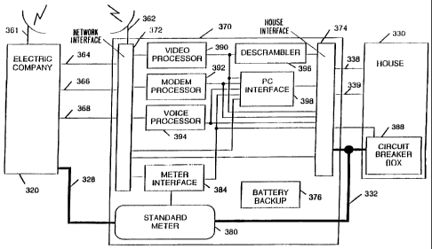
Figure 3 shows a third embodiment of associated
electronics for an electric meter according to the
invention with a detailed block diagram of a signal
processing computer 370 which provides an interface
between an electric company 320 and a house 330. The
computer 370 is located in the electric meter (not
shown). The electric company 320 provides digital data
services via network wireless transmission device 361 and
over fiber optic cables 364, coaxial cables 366, and
twisted pair cables 368. The computer 370 is coupled to
the digital data services through network interface 372.
Network interface 372 provides a remote wireless
transmission device 362 to communicate with network
wireless transmission 361. Such communication might
include transmitting and receiving signals over a
selected microwave frequency channel. Data transmission
on the selected frequency channel might include such
techniques as token ring data transmission, spread
spectrum transmission, and/or packet data transmission.
Alternatively, wireless transmission media might include
infrared, optical, cellular, or satellite communications.
CA 02784942 2012-07-31
WO 99/14606 PCTIUS97/16426
-11-
Computer 370 provides a video processor 390, a modem
processor 392, a voice processor 394, and a meter
interface 384, all of which are coupled to network
interface 372, house interface 374, and PC interface 398
for both receiving and transmitting their respective
signals. Computer 370 also provides a battery backup 376
to supply power to computer 370 in the event of a power
failure. Computer 370 may be operative upon occurrence
of such an event to notify electric company 320 of the
power failure.
Video processor 390 is further coupled to descrambler
396 for providing descrambled video signals to house
interface 374.
Network interface is coupled to PC interface 398.
Network interface 372 is further coupled directly to
house interface 374 for passing signals through without
other processing.
House interface 374 is coupled to house's internal
wiring including house's internal power lines 332,
telephone lines 338, and television coaxial cables 339.
The house interface 374 may also communicate with home
electronics via wireless communication. For example,
cordless telephones communicate over short range
microwave signals. The house interface 374 may utilize
similar short range wireless communication.
PC interface 398 is coupled to house interface 374
for providing personal computer functions to users in
house 330. Personal computer peripherals which require
user access, such as floppy disk drives, audio speakers,
and CD ROM drives, may be provided inside the house 330
and communicate with the PC interface 398 through the
house interface 374.
Electric company 320 provides electrical power
service over external power lines 328. External power
lines 328 are coupled through standard electric power
meter 380 to circuit breaker box 388. Circuit breaker
box 388 passes electrical power service to house over
house's internal power lines 332. Meter interface 384 is
CA 02784942 2012-07-31
WO 99/14606 PCT/US97/16426
-12-
coupled to standard electric power meter 380 and also to
circuit breaker box 388.
The embodiment shown in Figure 3 is advantageous with
respect to power management. For example, the electric
company 320 may produce a record of both power use and
factor by communicating periodically with meter interface
384. In addition to reduction in costs for meter
reading, the third embodiment may detect tampering or
attempts at bypassing the meter. The electric meter
according to the invention can also notify the utility
when there is a power outage. Another example is
advantageous billing arrangements. If there was a
problem with the customer's payments, the electric
company 320 could instruct the computer 370 to notify the
customer through, for example, a message on the
customer's television.
Regarding load management, the use of triacs or other
solid state switches in circuit breaker box 388 enables
the electric company 320 to selectively turn on and off
the power remotely to specific circuits. For example,
the electric company 320 might turn off hot water heater
circuits during excess power demands. In another example,
the triacs can be used to reduce the voltage if the power
company has excess power demands. Triacs could also be
used to remotely shut off power if there is evidence of
meter tampering, unpaid power bills or a change in the
account, such as a request for disconnect.
The electric meter according to the invention also
provides advantages for the customer's own energy
management. The customer can use the electric meter
according to the invention to control lights and
appliances. This system will permit the customer to
enjoy reduced rates by, for example, running the
dishwasher at the times of lowest power demands. The
interaction of the TV and internal power lines
advantageously permits the power user to control their
power use with the TV as a monitor. For example, the
electric meter according to the invention can be
CA 02784942 2012-07-31
WO 99/14606 PCTIUS97/16426
-13-
programmed to give different customers an individual
choice of lower power rates by controlling the timing of
different loads or higher rates with unrestricted use of
power.
The electric meter according to the invention also
advantageously provides each household with a personal
computer which can use a TV as a monitor. Software for
the personal computer may be supplied by the electric
company over the digital service network. For example,
the electric company might provide a "free" service for
school children to use for their homework. This has the
advantage of getting children used to using the software
made available by the electric company. The electric
meter according to the invention might also utilize the
personal computer to provide access to the internet and
for financial transactions. The electric company can
also provide programming to make it very easy for the
consumer to pay their power bills each month.
A regulated utility, like an electric company, can
justify the costs of the electric meter according to the
invention because it will reduce the costs to read meters
and it will provide significant help in power management.
The unregulated portion of the electric company can
obtain revenues from electronic communications. Recent
legislation has reduced regulation in communications and
this opens the field for the electric company which is
already connected to every house. The electric meter
according to the invention will enable the electric
company to be competition for both the telephone and
television cable companies and provides a strong
incentive for these companies to work with the electric
company by supplying a digital service network over
existing telephone and television lines.
Figures 4a and 4b show a side and a front view,
respectively, of a fourth embodiment of an electric meter
410 according to the invention wherein a connection is
made to a communication line 460.
CA 02784942 2012-07-31
WO 99/14606 PCT/US97/16426
-14-
Electric meter 410 has a meter enclosure 412 which
encloses standard electric power meter 480 and associated
electronics 470. Meter enclosure 412 forms a seal with
meter seal ring 418 to provide protection from the
elements. Electric meter 410 is mated with standard
meter box 414. External power lines 428 enter standard
meter box 414 from the top and are supplied to a house
through a power conduit 433 which exits standard meter
box 414 from the side.
Associated electronics 470 are coupled to
communication line 460 through a cable 465. Electric
meter 410 provides a stress relief 467 for cable 465.
Cable 465 is coupled to communication line 460 at
connection point 463. Signals are communicated in the
house over internal cable 436.
According to the fourth embodiment, communication
line 460 comprises, for example, a coaxial cable, a fiber
optic cable, or a twisted pair telephone line. In the
case of a coaxial cable, connection point 463 may be a
simple coaxial "T" connection. Connection point 463 may
otherwise be a "splice" type connection wherein signals
on communication line 460 are passed directly onto
internal cable 436 in addition to being processed by
associated electronics 470 over cable 465.
For example, communication line 460 may deliver
conventional television signals to the house, some of
which are scrambled. The conventional signals could be
delivered directly to the house for reception on a
conventional TV. Concurrently, via a "T" connection,
associated electronics may process the scrambled
television signals and deliver descrambled television
signals over the house's internal power lines for
reception by a remote device plugged into an electrical
wall outlet. The remote device would put the descrambled
signals back on conventional television coaxial cable or
conventional video and audio cables for reception on the
TV. Alternatively, the associated electronics may shift
CA 02784942 2012-07-31
75304-86D
-15-
and superimpose the descrambled television signal onto
internal cable 436 for reception on the conventional TV.
The utility meter according to the invention can
provide numerous advantageous applications to the user.
For example, the user can request information regarding
the user's utility usage and bill. The user may utilize
the utility meter according to the invention pay the
utility bill and other bills via credit card or other
payment arrangements.
Another example is information access. The utility
meter according to invention could provide a personal
computer for the user. The personal computer is configurable for a
number of purposes described below and can be interfaced to the user's
home electronics and appliances. The personal computer may have access
to various interactive computer services. For example, the user can
utilize the utility meter according to the invention to
access the internet and other information sources. The
user could use their home television set as a display.
The electric company may also provide computer software
and games for use on the personal computer.
Both the electric company and the user could use the
utility meter according to the invention advantageously
for load management. The electric company could, for
example, suspend electric service to non-essential
circuits, such as hot water heaters, during peak demand
times. The user could, for example, arrange to have the
dishwasher run during lower rate hours. The electric
company could also use the utility meter according to the
invention for remote meter reading and also for detect of
tampering by, for example, determining unusual power
usage. Power outages and other problems with the
electric company's distribution system can also be
detected by the utility meter according to the invention.
The utility meter according to the invention provides
a further advantage of being able to monitor and collect
data on the television viewing habits of the user. Such
information can be collected at the home and communicated
to the electric company over the communication network.
CA 02784942 2012-07-31
WO 99/14606 PCT/US97/16426
-16-
Such information is useful to determine the size of the
viewing audience for various different television
programs.
The utility meter according to the invention could
be used for interactive instructional programs in the
home. An instructional program could be viewed on the
user's television set and the user could, for example,
use a remote control device to respond to multiple choice
questions posed by the instructional program.
Other advantages include the ability for the electric
company to provide video signals, such as pay-per-view
programs, to the user. The signals may be scrambled at
the point of distribution and descrambled by the utility
meter according to the invention. The electric company
may also provide connection to various local and long
distance telephone services through the utility meter
according to the invention.
A particularly advantageous use of the utility meter
according to the invention might include monitoring a
personal medical alert device worn by a user inside the
home. Such a device might transmit medical data on a
periodic basis and be relayed to a physician through the
utility meter according to the invention. Alternatively,
such a device may be activated by the user to alert
emergency medical services through the utility meter
according to the invention. A similar advantage can be
achieved to monitor movements of a user restricted to
their homes by, for example, a court order.
Additional advantages and modifications will readily
occur to those skilled in the art. For example, an
alternative arrangement might include having the
associated electronics located in a junction box on the
utility pole or in another external location. While the
foregoing embodiments have been described with reference
to a house, it will be appreciated by one skilled in the
art that the invention is applicable to other residential
and commercial structures.
CA 02784942 2012-07-31
WO 99/14606 PCT/US97/16426
-17-
Therefore, the invention in its broader aspects is
not limited to the specific details, and representative
devices, shown and described herein. Accordingly,
various modifications may be made without departing from
the spirit or scope of the general inventive concept as
defined by the appended claims and their equivalents.