Note: Descriptions are shown in the official language in which they were submitted.
,
CA 2789607 2017-04-26
LED LIGHT FOR EXAMINATIONS AND PROCEDURES
[0001] Continue to [0002].
Field of the Invention
[0002] This application relates generally to the field of illumination, and
more particularly to an
LED illumination device for use by a physician or health care provider.
Background Of The Invention
[0003] Health care providers, during examinations and procedures, need
additional lighting to
better diagnose and treat different health conditions. It is important for
lighting to have proper
intensity, color temperature, and uniformity so that the provider is not
mislead when making a
diagnosis during the examination or procedure. The examination light may be
used in multiple
types of examinations and procedures; therefore, it is important for the
design of the light to
allow for the proper reach and positioning in order to illuminate any part of
the body by the
health care professional. It is equally important that once positioned, the
light does not drift
from this location, which can cause inconvenience especially when working in a
sterile
- 1 -
CA 02789607 2012-08-10
WO 2011/103073
PCT/US2011/024850
field. Examination lights with smaller product profiles are desirable as they
assist in
giving the provider better access to the patient.
[0004] Contemporary examination lights are generally not designed
specifically for interaction with examination and procedure chairs and tables,
limiting
their effectiveness when used as a system. The contemporary exam lights are
typically caster based, wall mounted, or ceiling mounted making them
cumbersome
for users and in some cases preventing accessibility to a patient. In other
cases,
these lights may assist in increasing room clutter.
[0005] Contemporary examination lights generally use halogen bulbs and
fiber
optic bundles that produce intense amounts of heat. Because of the halogen
bulb,
some lights require larger product envelopes. Furthermore, the halogen bulbs
utilized in the contemporary lights generally offer only hundreds to a few
thousand
hours of life. Blown bulbs may be costly and inconvenient especially if the
failure of
the bulb occurs in the middle of an examination or procedure. Moreover, as
these
light sources are manipulated to adjust a spot size of the light, the spots
generally
lose intensity as the spot size is increased, having health care professionals
choose
between more intense light or a larger spot of light. Therefore there is a
need in the
art to improve the life of the light source without degrading light intensity
would be a
noticeable improvement.
[0006] Some examinations and procedures may be hours in duration. Heat
generated from contemporary lamps can become uncomfortable for both the
provider and patient. Some contemporary lamps attempt to place the light
source in
the base of the light, away from the provider and the patient, but these
configurations
then require transmitting the light from the base of the light to the lamp
head as well
as fans or other heat dissipation components which are a source of noise and
add
- 2 -
CA 02789607 2012-08-10
WO 2011/103073
PCT/US2011/024850
Cost to the overall system. Therefore there is also a need in the art for a
light that
does not produce an abundance of heat over long periods of time.
[0007] Additionally, since it is likely the examination light could come
into
contact with different substances during the examination or procedure, the
design of
the light should provide some protection against the ingress of fluids. This
also helps
to ensure satisfactory operation of the light when cleaned with different
disinfectants.
Summary Of The Invention
[0008] Embodiments of the invention not only focus on designing an
examination light, but are also focused on the interaction between a user and
the
light. Embodiments of the examination light provide mounting locations that
allow
proper reach of the light source, provide a home storage position, and assist
in
reducing floor clutter by attaching the light to an examination chair or
examination
table. Mounting directly to the examination chair or table allows for maximum
accessibility to the patient and may aesthetically blend in with the chair or
table,
which also may assist in making the exam and procedure rooms more inviting to
a
patient.
[0009] In some embodiments, the location of the power switch is on the
light
head. This location may assist in eliminating the need for the user to reach
away
from the light head, which may be uncomfortable for the provider and patient.
A
recessed location of the power switch, in some embodiments, may make it easy
to
locate and may assist in preventing accidental activation of the switch.
[0010] The optical system, in some embodiments, allows light intensity and
uniformity to be met in a very short distance while using a LED as the light
source,
thus avoiding some of the issues related to contemporary halogen bulb lights.
This
- 3 -
CA 02789607 2012-08-10
WO 2011/103073
PCT/US2011/024850
short distance allows for a smaller light head, which adds to the ergonomics
of the
design and assists in positioning the light without obstructing the view of
the
healthcare provider. The LED light source produces a light beam that generally
does
not generate heat at the illumination site. Additionally, a predicted life for
the LED is
approximately a 50,000 hour life versus a few thousands of hours of their
counterpart
halogen bulbs.
[0011] Embodiments may also include a controller which is configured to
drive
more current through the LED effectively generating more foot-candles or lux
as the
spot size diameter is increased. This may assist in offsetting any loss in
light
intensity allowing for a system that can maintain intensity throughout the
spot size
range. A healthcare provider may now be able to increase the spot size without
suffering a loss of light intensity.
Brief Description Of The Drawinos
[0012] The accompanying drawings, which are incorporated in and constitute
a part of this specification, illustrate embodiments of the invention and,
together with
a general description of the invention given above, and the detailed
description given
below, serve to explain the invention.
[0013] FIG. 1 is a perspective view of an embodiment of the exam light.
[0014] FIG. 2 is a detailed view of the base of the exam light in FIG. 1.
[0015] FIG. 3 is a detailed view of the head of the exam light in FIG. 1.
[0016] FIG. 4 is an exploded view of components of the head of the exam
light
in FIG. 3.
[0017] FIG. 4A is a detailed view of components in FIG. 4.
[0018] FIG. 5 is a cross section view of the head of the exam light in FIG.
3
- 4 -
CA 02789607 2012-08-10
WO 2011/103073
PCT/US2011/024850
with the optical lenses in a first position.
[0019] FIG. 6 is a detailed view of the optical elements in the position in
FIG. 5
[0020] FIG. 7 is a detailed view of the optical mixing element in FIG. 6.
[0021] FIG. 8 is a cross section view of the head of the exam light in FIG.
2
with the optical lenses in a second position.
[0022] FIG. 9 is a detailed view of the optical elements in the position in
FIG.
8.
[0023] FIG. 10 is a block diagram of the components controlling the
intensity
of the light emitted from the exam light of FIG. 1.
[0024] It should be understood that the appended drawings are not
necessarily to scale, presenting a somewhat simplified representation of
various
features illustrative of the basic principles of the invention. The specific
design
features of the sequence of operations as disclosed herein, including, for
example,
specific dimensions, orientations, locations, and shapes of various
illustrated
components, will be determined in part by the particular intended application
and use
environment. Certain features of the illustrated embodiments have been
enlarged or
distorted relative to others to facilitate visualization and clear
understanding. In
particular, thin features may be thickened, for example, for clarity or
illustration.
Detailed Description Of The Invention
[0025] Embodiments of the invention provide an examination light that
delivers
lighting with proper intensity, color temperature and uniformity to assist in
enabling a
medical provider in providing proper diagnoses. Embodiments allow the light to
be
used in multiple types of examinations and procedures by providing an adequate
reach and positioning to assist in illuminating any part of the body without
drifting
- 5 -
CA 02789607 2012-08-10
WO 2011/103073
PCT/US2011/024850
from its location. Embodiments of the invention also allow for the ability to
adjust the
spot size from a minimum range to a maximum range assisting the provider in
being
able to direct light only where needed. Additionally, embodiments of the
invention
also provide an auto-intensity functionality, driving more light to an
increased spot
size, assisting in minimizing intensity roll-off.
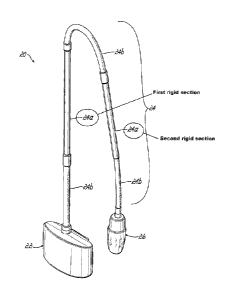
[0026] Turning now the embodiment of the examination light 20 in FIG. 1,
the
light 20 includes a base component 22, an arm 24 with both rigid 24a and
flexible
24b sections, and a lamp head 26. The combination of rigid 24a and flexible
24b
sections of the arm 24 assist in moving the lamp head 26 to various positions
by the
health care provider and assists the provider in directing the light toward
the
examination and/or treatment area on a patient. The base component 22 of the
examination light 20 provides a mounting structure (not shown) which allows
the light
20 to be mounted to an examination table, chair, or other fixture, such that
the
examination light 20 is available for use by the health care provider.
[0027] The examination light 20 is electrically powered through an
electrical
connection to an AC source in a wall socket or the like. As seen in FIG. 2,
the
source of electrical AC power enters the base component 22 at connection 28
which
is in turn electrically connected to a circuit board 30. Components on the
circuit
board 30 convert the AC power to DC which is used to power the components in
the
lamp head 26. The DC power is delivered to the lamp head 26 through wires
extending from the circuit board 30 through the arm 24. By placing the
electrical
conversion circuitry in the base component 22, any heat generated by that
circuitry is
located away from the health care provider and the patient.
[0028] FIG. 3 provides additional detail for the lamp head 26. The
examination lamp 20 is controlled by a control area 32 on the lamp head 26. In
- 6 -
CA 02789607 2012-08-10
WO 2011/103073
PCT/US2011/024850
some embodiments, this control area 32 may include a single button 34 which
may
be used to turn the light 20 on, cycle through preset brightness levels, and
turn the
light 20 off. In other embodiments, multiple buttons 34 may be employed with
one
button being dedicated to turning the light 20 on and off and other buttons
being
used to adjust the brightness of the light 20. The control area 32 is located
on a
proximal portion 36 of the lamp head 26, which is coupled to the arm 24 and
remains
in a fixed position with respect to the arm 24. A distal portion 38 of the
lamp head 26
rotates with respect to the proximal portion 36 in both a clockwise and a
counter-
clockwise direction. The rotation of the distal portion 38 may be limited in
each of
the clockwise and counter-clockwise directions by stops within the distal
portion 38.
Rotation of the distal portion 38 causes relative motion of components within
the
lamp head 26 to adjust the spot size of the light emitted from an exit
aperture 40 of
the lamp head 26.
[0029] As seen in more detail in FIG. 4, a cylinder 42 with slots 44a, 44b,
44c
is fixed to a housing 46 within the proximal portion 36 of the lamp head 26. A
lens
48 is located within the cylinder 42 near the housing 46. Protrusions 50a,
50b, 50c
extending from an edge of the lens 48 are aligned with the slots 44a, 44b, 44c
within
the cylinder 42 allowing the lens to move along an axis normal to the lens 48.
A
second lens 52 is also located within the cylinder 42 and distally from the
lens 48.
Protrusions 54a, 54b, 54c extending from an edge of the lens 54 are also
aligned
with the slots 44a, 44b, 44c within the cylinder 42 allowing the lens to move
along an
axis normal to the lens 52. Components 56a, 56b, 56c, illustrated in an
exploded
view in FIG. 4, contain slots 58a, 58b, 58c in which the protrusions 50a, 50b,
50c of
lens 48 are also located. Components 56a, 56b, 56c are coupled with the distal
portion 38 of the lamp head 26. As the distal portion 38 of the lamp head 26
are
- 7 -
CA 02789607 2012-08-10
WO 2011/103073
PCT/US2011/024850
rotated, components 56a, 56b, 56c and their associated slots 58a, 58b, 58c and
60a,
60b, 60c are also rotated.
[0030] When assembled, slots 58a, 58b, 58c intersect slots 44a, 44b, 44c
respectively. Similarly, slots 60a, 60b, 60c also intersect slots 44a, 44b,
44c. An
example of theses intersections may be seen in the detailed view in FIG. 4A.
Intersection 62 occurs where slot 58a of component 56a crosses slot 44a of
cylinder
42. Protrusion 50a of lens 48 is positioned at intersection 62. The other
protrusions
50b, 50c of lens 48 are positioned similarly in similar intersections (not
shown).
Additionally, intersection 64 occurs where slot 60a of component 56a crosses
slot
44a of cylinder 42. Protrusion 54a of lens 52 is positioned at intersection
64. The
other protrusions 54b, 54c of lens 52 are positioned similarly in similar
intersections
(not shown). As the components 56a, 56b, 56c are rotated, the intersection
point
moves along the slots 44a, 44b, 44c thus moving the lenses 48, 52 relative to
one
another.
[0031] FIG. 5 shows a cross section of the lamp head 26 with the lenses 48,
52 in a first position at one of the extremes of the light. As can be seen in
the cross
section, DC power is delivered through arm 24 connected to the proximal
portion 36
of the lamp head 26. Circuit board 66 receives the DC power (not shown) as
well as
control signals from the control area 32. Circuit board 66 also contains the
drive
controls for LED 70, the source of the light for the examination light 20.
Circuit board
66 is connected to circuit board 68, which contains the LED 70 and a current
sense
resistor providing feedback to circuit board 66. Other embodiments may contain
alternate configurations of the circuit boards with single or multiple boards
being
used. In multiple board embodiments, components may be distributed in many
configurations. The drive controls on circuit board 68 drive LED 70 according
to a
- 8 -
CA 02789607 2012-08-10
WO 2011/103073
PCT/US2011/024850
desired output level. Light emitted from LED 70 is collected in mixing element
72.
Light exits mixing element 72 at an exit face 74 and is directed toward both
lenses
48, 52. Light is then magnified by lenses 48, 52 to generate the desired spot
size.
[0032] FIG. 6 illustrates the magnification of the light with the lenses
48, 52 in
the position shown in FIG. 5. For clarity, only the optical elements are shown
in FIG.
6. As can be seen in the figure, light rays 76 emitted from LED 70 are
collected in
mixing element 72 and directed from the exit face 74 first to lens 48. Light
rays 76
are first magnified by lens 48 and while being directed to lens 52. Lens 52
further
magnifies the light rays 76 resulting in a spot 78. In this configuration,
spot 78 is at
its maximum size (42 times magnification).
[0033] Specifically, and with reference to both FIGS. 6 and 7, light from
the
LED 70 (a Luxeon K2 in some embodiments, though other LEDs may also be used),
which is encapsulated in a nearly hemispherical epoxy lens, is sent to an
output face
via refraction at a positive optical surface, followed by Total Internal
Reflection
("TIR") at a parabolic initial phase 80 of the mixing element 72 and thereby
via
additional TIR along the cylindrical final stage 82 of the mixing element.
Some of the
emission from the LED 70 also proceeds directly without TIR to the output face
74,
being affected only by the initial refractive surface.
[0034] The exit face 74 is then re-imaged via a 3:1 zoom lens (lenses 48,
52)
to a constant final position. The zoom lens operates over a magnification
range of
approximately 14x to 42x. The zoom lens comprises the two positive acrylic
optical
elements, lens 48 and lens 52. A typical prescription of the zoom lens is
attached in
the appendix at the end of this disclosure.
[0035] FIG. 8 illustrates a cross section of the lamp head 26 with lenses
48,
52 at the opposite extremes. In this configuration, an as additionally seen in
the
- 9 -
CA 02789607 2012-08-10
WO 2011/103073
PCT/US2011/024850
simplified view in FIG. 9, light rays 76 from LED 70 are sent to the parabolic
initial
phase 80 of the mixing element 72 and thereby via additional TIR along the
cylindrical final stage 82 of the mixing element. Light rays 76 then first
magnified by
lens 48 and while being directed to lens 52. Lens 52 further magnifies the
light rays
76 resulting in a spot 78. In this configuration, spot 78 is at its minimum
size (14
times magnification).
[0036] As the health care provider rotates the distal portion 38 of the
lamp
head 26 between the extremes illustrated in FIGS. 5, 6, 8 and 9, the lenses
48, 52
making up the zoom lens move towards or away from one another, thus adjusting
the spot size 78 of the examination light 20. In some embodiments, masking
elements may also be used with the optics to assist in controlling the spot
size.
[0037] At a given distance from the exit aperture 40, and with a fixed
light (i.e.
LED 70) output, as the target spot size 78 is increased, the light density
will generally
decrease. Similarly, if the spot size 78 is decreased, the light density will
generally
increase. Therefore, embodiments of the invention include a controller that
adjusts
the brightness of the light 20 to maintain a constant light density as the
spot size 78
of the light 20 is changed.
[0038] If the spot size 78 is known, the output from LED 70 could be
increased
or decreased appropriately to maintain a constant light density in the spot
78. The
spot size is proportional to lens travel. Therefore, if the position of the
lens is known,
the spot size is known. This position can be used by a controller 84 to adjust
the
drive current of the LED, which in turn adjusts the light density.
[0039] The size of the spot is ur2. Therefore, as the spot radius (i.e. r)
is
increased, the light density decreases as a squared function, since the same
amount
of light is spread over a larger area dictated by r2. If the desired light
intensity is
- 10 -
CA 02789607 2012-08-10
WO 2011/103073
PCT/US2011/024850
achieved with an LED drive current Inn, at the smallest spot size, rm,n, then
a
constant intensity may be achieved over any spot size (r) by setting the LED
drive
current (I) to:
r r2
= H (1)
[0040] Referring now to the block diagram in FIG. 10, the position of the
lens
is determined using a magnetic position sensor 86 mounted in a fixed position
on
circuit board 66 in the proximal portion 36 of the lamp head 26. A neodymium
magnet 88 (or other permanent magnet) is mounted on the rotatable distal
portion 38
of the lamp head 26. As the distal portion 38 is rotated, an angle 90 between
the
magnet 88 and the centerline of the sensor 86 is changed. The change may be
reflected in dual outputs 92, 94 of the sensor 86. The outputs 92, 94 of the
sensor 86
may be conditioned with instrumentation amplifiers 96, 98 and fed into two
channels
of the controller's 84 A/D converters 100, 102.
[0041] Samples from the A/D converters 100, 102 may be filtered with a
single-pole, low-pass filter 104, 106. In some embodiments the A/D converters
100,
102 and low pass filters 104, 106 may be integral with the controller 84. In
other
embodiments, one or more of the A/D converters 100, 102 or low pass filters
104,
106 may be separate from but in electrical communication with the controller
84.
The filtered measurements may then be fed into a linear interpolation routine
108
that uses lookup tables to approximate non-linear functions. One A/D channel
100
may be used to select the appropriate lookup table 110, while the other
channel 102
may be fed as the input (x-axis) 112 of the interpolation routine. In other
embodiments, other methods of determining solutions to the non-linear
functions
may be used. An output of the interpolation routine 108 is a "boost" factor.
The
- 11 -
CA 02789607 2012-08-10
WO 2011/103073
PCT/US2011/024850
boost factor multiplies the nominal drive current (the current Im,, at the
smallest spot
size, rmin).
[0042] In some embodiments, the magnetic sensor may be temperature
sensitive. This temperature sensitivity may also be dependent on the angle of
the
magnetic field. Therefore, one of the position A/D channels 100, 102 may be
fed into
another interpolation routine 114 that may also use a lookup table, with an
output of
this routine being the temperature sensitivity. A temperature of the circuit
board 66
may be measured with a third A/D channel (not shown) and an internal
temperature
sensor 116, either inside the controller 84 or in other embodiments the
temperature
sensor may be located on the circuit board 66. The table sensitivity may be
multiplied by the measured temperature and may be used to compensate the boost
factor.
[0043] The raw boost factor from the position routine 108 may then be
multiplied by the temperature error factor 118, and the nominal current Imin
may then
multiplied by the corrected boost factor resulting in a final drive current,
I. This final
current is controlled via a duty cycle, 0 ¨ 100%. The duty cycle is used to
set a timer
counter register 120 in the controller 84 to output a PWM driver to an LED
controller
122. The LED controller 122 may be a constant current device, which is
configured
to set the maximum current with 100% duty cycle. Therefore, any duty cycle
less
than 100% proportionally reduces the drive current to the LED 70, and thus
adjusts
the intensity of the light 76 emitted from the LED 70, and thus may be used to
keep
the light density of the spot approximately constant.
[0044] While the present invention has been illustrated by a description of
one
or more embodiments thereof and while these embodiments have been described in
considerable detail, they are not intended to restrict or in any way limit the
scope of
- 12 -
CA 02789607 2012-08-10
WO 2011/103073
PCT/US2011/024850
the appended claims to such detail. Additional advantages and modifications
will
readily appear to those skilled in the art. The invention in its broader
aspects is
therefore not limited to the specific details, representative apparatus and
method,
and illustrative examples shown and described. Accordingly, departures may be
made from such details without departing from the scope of the general
inventive
concept.
- 13 -
CA 02789607 2012-08-10
WO 2011/103073 PCT/US2011/024850
APPENDIX
Typical Prescription of the Zoom Lens
Zoom
Cycle Number = 0, Phi Value = 0.00E+00
Lens Data
Surf Clear Aperture
No. Type Radius Thickness Glass Diameter
1 00 -1000.00000 8.00
2 Aperture stop 1000.00000 700.00
3 00 Space 1 8.00
4 ac 24.0000 3.96000 ACRYLIC 10.50
-10.0000 Space 2 10.50
6 ac 135.0000 5.60000 ACRYLIC 19.70
7 ac -15.4000 413.00000 19.70
8 00 Image distance 400.00
Symbol Description
a - Polynomial asphere
c - Conic section
Even Polynomial Aspheres and Conic Constants
Surf.
No.
4 -5.0000E+00 0.000000E+00 0.000000E+00 0.000000E+00 0.000000E+00 0.000000E+00
6 1.2000E+02
0.000000E+00 0.000000E+00 0.000000E+00 0.000000E+00 0.000000E+00
7 -1.3000E+00 0.000000E+00 0.000000E+00 0.000000E+00 0.000000E+00 0.000000E+00
Variable Spaces
Zoom Space 1 Space 2 Image Focal
Pos. T(3) T(5) Distance Shift
1 0.500 24.500 0.231 142.000
2 6.200 0.500 18.676 547.000
What Is Claimed Is:
- 14 -