Note: Descriptions are shown in the official language in which they were submitted.
CA 02793780 2012-10-24
ROTOR BLADE FOR A WIND POWER PLANT
The invention concerns a rotor blade of a wind power installation,
and a wind power installation. As-state of the art in this respect attention
should be directed generally to the book 'Windkraftanlagen', Erich Hau,
1996. That book contains some examples of wind power installations, rotor
blades of such wind power installations as well as cross-sections of such
rotor blades from the state of the art. Page 102, Figure 5.34, illustrates the
geometrical profile parameters of aerodynamic profiles in accordance with
NACA. It is to be seen in that respect that the rotor blade is described by a
profile depth which corresponds to the length of the chord, a greatest
camber (or camber ratio) as the maximum rise of a median line over the
chord, a camber reserve, that is to say the location with respect to the
profile depth where the greatest camber is provided within the cross-
section of the rotor blade, a greatest profile thickness as the largest
diameter of an inscribed circle with the centre point on the median line and
the thickness reserve, that is to say the location with respect to the profile
depth where the cross-section of the rotor blade assumes its greatest
profile thickness. In addition the leading-edge radius and the profile co-
ordinates of the underside and the top side are brought into consideration
to describe the cross-section of the rotor blade. The nomenclature known
from the Erich Hau book is to be retained inter alia. for the further
description of the cross-section of a rotor for the present application.
Rotor blades are to be optimised in regard to a large number of
aspects. On the one hand they should be quiet while on the other hand
they should also afford a maximum dynamic power so that, even with a
quite slight wind, the wind power installation begins to run and the nominal
wind speed, that is to say the speed at which the nominal power of the
wind power installation is also reached for the first time, is already reached
at wind strengths which are as low as possible.
1
CA 02793780 2012-10-24
If then the wind speed rises further, nowadays when considering
pitch-regulated wind power installations the rotor blade is increasingly set
into the wind so that the nominal power is still maintained, but the
operative surface area of the rotor blade in relation to the wind decreases
in order thereby to protect the entire wind power installation or parts
thereof from mechanical damage. It is crucial however that great
significance is attributed to the aerodynamic properties of the rotor blade
profiles of the rotor blade of a wind power installation.
The object of the present invention is to provide a rotor blade having
1o a rotor blade profile and a wind power installation, which involve better
efficiency than hitherto.
In accordance with the invention that object is attained by a rotor
blade having a rotor blade profile with the features as set forth in one of
the independent claims. Advantageous developments are described in the
appendant claims.
The specific co-ordinates of a rotor blade profile according to the
invention are set forth in a Table 1.
The invention is illustrated hereinafter by a number of drawings in
which:
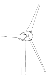
Figure 1 shows a perspective view from the front of a wind power
installation according to the invention,
Figure 2 shows a perspective view of a wind power installation
according to the invention from the rear and the side,
Figure 3 shows a view of a wind power installation according to the
invention from the side,
Figures 4 - 8 show views of a rotor blade according to the invention
from various directions,
Figure 9 shows a view on an enlarged scale of a wind power
installation according to the invention,
Figure 10 shows a view of a rotor blade according to the invention,
Figures 11 - 17 and 19 show various views of a wind power
installation according to the invention, and
2
CA 02793780 2012-10-24
Figure 18 shows a cross-section of a rotor blade according to the
invention (in the region near the hub).
The rotor, blade profile described in accordance with the present
application is provided in particular in the region of the rotor blade which
adjoins the rotor blade connection (for connection to the hub). Preferably
the profile described in the present application is provided in the first
third
of the rotor blade, with respect to the overall length of the rotor blade. In
this respect the overall length of a rotor blade may definitely be in the
range of between 10 m and 70 m, depending on the nominal power which a
wind power installation is to involve. Thus for example the nominal power
of a wind power installation from the- corporation Enercon of type E-112
(diameter about 112 m) is 4.5 MW while the nominal power of a wind
power installation from Enercon of type E-30 is 300 KW.
What is particularly characteristic in terms of the profile of the rotor
blade according to the invention is that the greatest profile thickness is
between about 25% and 40%, preferably between 32% and 36%, of the
length of the rotor blade chord. In Figure 18 the greatest profile thickness
is about 34.6% of the length of the rotor blade chord. Shown in Figure 1 is
a chord 1 which extends from the centre 2 of the rotor blade trailing edge 3
to the foremost point 4 of the rotor blade leading edge 5. The thickness
reserve, that is to say the location in relation to the blade length where the
greatest profile thickness occurs, is between about 20% and 30% of the
length of the chord, preferably between 23% and 28%, in the illustrated
example being 25.9%. The greatest thickness was ascertained
perpendicularly to the chord and the reserve is related to the rotor blade
leading edge.
In addition Figure 18 shows what is known as the mean camber line
7. That camber line results from half the respective thickness of the rotor
blade 8 at a point. Accordingly that camber line does not extend in a
straight line but always exactly between oppositely disposed points on the
increased-pressure side 9 of the rotor blade 7 and the reduced-pressure
side 10 of the rotor blade 7. The camber line intersects the chord at the
trailing edge of the rotor blade and the leading edge of the rotor blade.
3
CA 02793780 2012-10-24
The camber reserve in the cross-section of a rotor blade according to
the invention is between about 55% and 70% of the length of the chord,
preferably between about 59% and 63%. In the illustrated example the
camber reserve is about 61.9% of the length of the chord. In this case the
greatest camber is between about 4% and 8% of the length of the chord,
preferably between about 5% and 7% of the length of the chord. In the
illustrated example the camber is about 5.87% of the length of the chord.
It is further particularly striking in terms of the profile of the rotor
blade according to the invention that the increased-pressure side of the
rotor blade 'cuts' the chord twice, that is to say in that region the
increased-pressure side of the profile is of a concave configuration while in
the front region of the profile the increased-pressure side is of a convex
configuration. In the region where the increased-pressure side is of a
convex configuration, in the corresponding, oppositely disposed region on
the reduced-pressure side, the latter is delimited by an almost straight line.
It may certainly have been known for the increased-pressure side to
be provided with a concave curvature or for the reduced-pressure side to
be provided with a straight-line boundary. In particular the combination of
those two measures is however of great significance for the profile of a
rotor blade according to the invention and is characteristic in respect of the
rotor blade profile according to the invention.
The rotor blade trailing edge of the illustrated profile is also
noticeably thick. That however does not cause any problem in regard to the
creation of sound at the trailing edge of the rotor blade because the
illustrated profile is in the inner third of the rotor circle and there the
orbital
speed is not very high.
The x-y-co-ordinates of the profile shown in the Figure are
reproduced in Table 1 and thus the profile of the rotor blade according to
the invention is exactly described therewith.
To improve the aerodynamic shape of the rotor blade, it is of such a
configuration, in the region of the rotor blade root, that there it is of its
greatest width and thus the rotor blade is of a trapezoidal shape (in plan)
which is more or less approximated to the optimum aerodynamic shape.
4
CA 02793780 2012-10-24
Preferably in the region of the rotor blade root the rotor blade is of such a
configuration that the edge of the rotor blade root, which is towards the
pod of a wind power installation, is adapted to the external contour of the
pod in at least one angular position, for example it is adapted in such a way
that a very small spacing, for example a spacing of between about 5 mm
and 100 mm, exists between the pod and the edge of the rotor blade root
which is towards the wind power installation and the external contour of the
pod when the rotor blade is positioned in the nominal wind position.
A rotor blade with the above-indicated properties affords a
significantly higher increase in power, in part up to 10%. By virtue of that
increase in power which could not be predicted, a wind power installation
according to the invention, at a given wind speed below the nominal wind
speed, achieves a higher power output. In addition it reaches its nominal
power output earlier than hitherto. Accordingly the rotor blades can also be
rotated (pitched) earlier and this provides that the level of sound emission
on the one hand and the mechanical loading on the installation on the other
hand fall.
In that respect the invention is based on the realisation that the
rotor blade shape which is common nowadays is investigated in a wind
tunnel admittedly using different wind speeds but with an air flow which is
always uniform. As in nature however it is in the rarest cases that the wind
blows uniformly in terms of surface area, but rather is subject to a
stochastic law, the known rotor blades, as a consequence of gusts, involve
detachment of the flow precisely in the inner region of the blade near the
rotor hub where the blade is in fact no longer of an aerodynamically clean
and optimum configuration. That flow detachment phenomenon is
propagated a distance along the rotor blade in the direction of the outer
region thereof (rotor blade tip). As a result the flow can become detached
from the rotor blade in a bubble-shaped region and thus result in
corresponding power losses. In the case of the present invention and
having regard to the above-described basic situation therefore it is possible
to achieve a considerable increase in power output by virtue of a rotor
5
CA 02793780 2012-10-24
blade which is of a clean configuration also in the inner region of the rotor
blade.
If now a known standard profile were to be used instead of the
empirically ascertained profile which is proposed in the present application,
then, to afford an aerodynamically clean configuration for the rotor blade,
approximately double the profile depth (this corresponds to the length of
the chord of the rotor blade) would be required in the lower rotor blade
region (the region near the hub). The great profile thickness in the front
region however is required for securely and reliably transmitting the loads
involved and to attain a lift value CA of greater than 2.
As is known from the state of the art, rotor blades are nowadays
usually constructed, which entail a great saving in material to the greatest
possible extent in the inner region. Typical examples in that respect are
disclosed in the state of the art which has already been referred to above,
in 'Windkraftanlagen', Erich Hau, 1996, on pages 114 and 115. It can be
seen therein that the greatest profile depth is always attained at a certain
distance from the rotor blade connection, that is to say in the region near
the rotor blade connection, in which respect material is saved in those rotor
blades in accordance with the state of the art. If however an optimum
shape which approximates to a trapezoidal shape is used in plan, then the
greatest width of a rotor blade is not for example at a spacing relative to
the rotor blade connection but precisely in the region of the rotor blade
connection itself. That structure then therefore does not save the greatest
possible amount of material in the inner region of the rotor blades.
The cause of the saving in material which has been implemented
hitherto lies in the static manner of considering the flow conditions (as
described hereinbefore) in regard to calculating/developing the rotor
blades. Added to that is the fact that current calculation programs for rotor
blades divide the rotor blade into individual spacings and calculate each
rotor blade portion in itself in order to derive therefrom the evaluation for
the overall rotor blade.
It will be noted however that the reality looks somewhat different.
On the one hand the wind does not blow uniformly and statically within a
6
CA 02793780 2012-10-24
giverT- surface area region but markedly exhibits a stochastic behaviour,
while on the other hand, by virtue of the low peripheral speed of the rotor
blade in the inner region (that is to say in the region near the rotor hub)
the influence of the wind speed is considerable and accordingly the angle
of incidence changes in that region with a high level of dependency on the
instantaneous wind speed. As a consequence thereof detachment of the
flow from the rotor blade also correspondingly frequently occurs in the
inner region of the rotor blade.
A hysteresis effect is operative in such a situation. When the
previous wind speed occurs again, that is to say after a gust is past, the
flow is not the same at the rotor blade again. Rather, the wind speed firstly
has to fall further (the angle of incidence must therefore be further
changed) until the flow again bears against the surface of the rotor blade.
If however the wind speed does not fall further, it may certainly happen
that, for a prolonged period of time, in spite of the afflux flow of the wind
to
the rotor blade, a relevant force is exerted on the rotor blade because the
flow has not yet come to lie against the rotor blade surface again.
The risk of flow detachment is markedly reduced by virtue of the
configuration according to the invention of the rotor blade. That
detachment risk is also reduced by the relatively thick profile. The
considerable increase in power can also be well explained by virtue of the
fact that, due to the hysteresis effect, once flow detachment has occurred,
the power losses are maintained over a considerable period of time (for
rotor blades in accordance with the state of the art).
A further part of the increase in power can be explained by virtue of
the fact that the wind follows the path of least resistance. If therefore the
rotor blade is very thin in the inner region near the hub (great saving of
material), that is equivalent to a 'slip hole' in the harvesting area of the
rotor circle, through which hole the air preferentially flows. In this case
also
it is certainly possible to see a weakness in the common calculation
programs which are always based on uniform distribution over the rotor
circle area.
7
CA 02793780 2012-10-24
If now that 'slip hole' is 'closed' by virtue of the trapezoidal
configuration of the rotor blade in the region near the hub, that will afford
improved distribution of the air flow over the entire circular surface area
and thus the effect on the outer region of the rotor blade is also increased
somewhat. Accordingly therefore the step of 'closing' that 'slip hole' makes
a contribution to the higher power output of the rotor blade according to
the invention.
This is a further weak point of the current calculation programs for
they also consider the rotor blade portion directly adjoining the 'slip hole'
as
a full-value rotor blade portion which it cannot be, because of the particular
flow conditions (frequent flow breakdowns and later restoration of the
intended flow conditions).
Figures 11 to 17 show a view of a wind power installation according
to the invention from the front or from the side. It can be seen in that
respect how the three rotor blades have an almost seamless transition into
the external configuration of the pod,. in the blade region near the hub. This
applies however only in regard to the position of the rotor blades insofar as
they are in the nominal wind position.
If the wind then rises further above the nominal wind, then as usual
the rotor blades are moved slowly out of the wind by pitch control (pitch
regulation), and Figure 15 shows that in that case there is indeed a larger
spacing between the lower edge of the rotor blade in the inner region and
the pod. Figure 4 however also shows that provided on the outside of the
pod is a structure which in its cross-section very substantially corresponds
to the profile of the rotor blade in the region near the hub and which, when
the rotor blade is set in an angle of incidence at the nominal speed, is
directly below the rotor blade so that there is only a small gap between the
structure and the rotor blade in the region near the hub.
Accordingly the external contour of the pod also includes a part of
the rotor blade, which is not an integral constituent part of the rotor blade.
In the case of the rotor blade profile shown in Figure 18, the leading
edge radius is approximately 0.146 of the profile depth.
8
CA 02793780 2012-10-24
As can be seen from Figure 18, provided at the reduced-pressure
side is a longer, almost straight region. That can be described for example
as follows: in the region at between 38% and 100% of the profile depth the
radius is 1.19 times the length of the profile depth. In the region of
between 40% and 85% of the profile depth (see Figure 18) the radius is
about 2.44 multiplied by the profile depth. In the region of between 42%
and 45% of the profile depth the radius is about 5.56 of the profile depth.
In the region of between 36% and 1009/o of the profile depth the
maximum deviation from the ideal straight line is about 0.012 of the profile
length. That value is the crucial value as the curvature radius varies and
the greatest curvature radius is already specified in the respective regions.
In the illustrated example the length of the reduced-pressure side is
about 1.124 of the length of the profile depth while the length of the
increased-pressure side is 1.112 of the length of the profile depth. This
means that the reduced-pressure side is only immaterially longer than the
increased-pressure side. It is therefore highly advantageous if the ratio of
the reduced-pressure side length to the increased-pressure side length is
less than 1.2, preferably less than 1.1 or in a range of values of between 1
and 1.03.
It can be seen from the illustrated Figures that the rotor blade has its
greatest profile depth directly at the spinner, that is to say at the outside
of
the pod of the wind power installation. Thus for example in the case of a
wind power installation with a rotor diameter of 30 m, the profile depth at
the spinner is between about 1.8 and 1.9, preferably 1.84. If then the
spinner is approximately of a diameter of 3.2 mm, the ratio of the profile
depth of the rotor blade at the spinner to the spinner diameter is about
0.575. It is therefore highly advantageous if the ratio of the profile depth
to
the spinner diameter is greater than a value of 0.4 or in a range of values
of between 0.5 and 1. In that respect each value can be assumed to be in
the above-indicated range. In the above-specified example the ratio of the
profile depth to the rotor diameter is about 0.061. It is apparent that
therefore the 'slip hole' is as small as possible if the ratio of the profile
depth to the rotor diameter is greater than a value of between 0.05 and
9
CA 02793780 2012-10-24
0.01, in which respect the value given by way of example has proven to be
extremely appropriate, as regards the efficiency of the rotor blade.
Another example would be a rotor blade with the profile cross-
section shown in Figure 18, in the first third, in which respect the profile
depth at the spinner is about 4.35 mm, the spinner diameter is 5.4 m and
the rotor diameter is overall 71 m. Then the value of the profile depth to
the spinner diameter is 0.806 and the ratio of the profile depth to the rotor
diameter is again 0.061. The above-indicated values relate to a triple-blade
rotor with pitch regulation.
As described, in the case of the rotor blade according to the
invention the widest location (the location with the greatest profile depth)
of the rotor blade can be directly in the region of the blade connection. The
blade connection is the region in which the rotor blade is connected (joined,
screwed and so forth) to the hub of the wind power installation. In addition
the lower edge of the rotor blade, that is to say the edge which faces
towards the pod of the wind power installation, is very substantially
adapted to or matched to the external contour of the pod in the longitudinal
direction. Accordingly in this case, when a rotor blade is in the feathered
position (practically no longer any surface area which faces towards the
wind), the rotor blade is parallel to the lower edge that is towards the pod
and the spacing between the lower edge and the external contour of the
pod is at a minimum, preferably being less than 50 cm or even better less
than 20 cm.
When now that rotor blade is set into the wind, it involves a surface
area of maximum size even in the very near region of the rotor blade (the
slip hole is very small). The above-mentioned reference Erich Hau shows
that the rotor blade in the state of the art decreases regularly in the region
near the hub (the rotor blades are there less wide than at their widest
location) and conversely in the case of the rotor blade according to the
invention the widest location is precisely in the region near the hub so that
there the wind potential can also be utilised to the best possible extent.
As is known, it is precisely when dealing with very large rotor blades
that a very great rotor blade width is involved in the region near the hub.
CA 02793780 2012-10-24
So that such rotor blades can still be transported (in the case of large rotor
blades, that is to say rotor blades which are longer than 30 m, the width of
the rotor blade in the region near the hub can certainly be between 5 m
and 8 m), the rotor blade can be of a two-part configuration, in which case
the two parts are separated during transport and can be fitted together
after transport. For that purpose the two parts are connected together
before being installed on the wind power installation, for example by way of
screw connections and non-releasable connections (adhesive). That is no
problem in particular when dealing with large rotor blades as, by virtue of
their size, the rotor blades are also accessible from the interior for being
fitted together so that this affords a rotor blade of a unitary appearance to
the exterior and separation lines at the parts when fitted together are
scarcely visible or not visible at all.
As initial measurements show, the rotor blade design according to
the invention can markedly increase the efficiency in comparison with
previous rotor blades.
As can be seen from Figures 1 to 17, in the case of a wind power
installation 1 according to the invention the rotor blades are of such a
configuration that they have their greatest profile depth in the region near
the hub and in addition the rotor blades, along their entire profile, are
moved in the region near the hub to be very close to the pod cladding
(spinner) of the machine housing of the wind power installation.
Accordingly, at least for the position in which the rotor blade assumes an
angle which is adopted at wind speeds up to the nominal wind range, that
means that there is a very small spacing relative to the pod cladding.
While, in the view as shown for example in Figures 1, 2 and 3, the rotor
blades are also moved very close to the outer cladding of the pod with the
rear part of their profile, an alternative embodiment as is shown for
example in Figures 11 to 17 provides that the outer cladding of the pod is
provided with a rotor blade portion 30 itself, which however is itself not an
integral constituent part of the overall rotor blade. Thus it can be clearly
seen in particular from Figures 15 and 17 that the rotor blade part which is
provided on the outside of the pod is fixed there and is arranged at an
11
CA 02793780 2012-10-24
angle corresponding to the angular position of a rotor blade up to the
nominal wind speed, so that, at least at wind speeds up to the nominal
wind, there is a minimal gap between the lower edge of the rotor blade
even in the rear region of the profile depth, and the pod.
It can also be clearly seen from Figure 19 that there is only a quite
small 'slip hole' for the wind by virtue of the configuration according to the
invention of the rotor blades at the centre of the rotor.
Figure 18 shows a cross-section through a rotor blade according to
the invention as taken along line A-A in Figure 17, that is to say the profile
of the rotor blade in the region near the hub.
Figure 17 also includes an indication of what is to be understood by
the diameter D of the spinner.
The rotor diameter is described by the diameter of the circular area
which is covered by the rotor when it rotates.
As can be seen from Figure 15 and other Figures the part 30 of the
rotor blade which is not an integral constituent part of the rotatable rotor
blade is an integral constituent part of the outside cladding of the pod. The
respective part can be screwed to the pod or can also be glued or joined in
one piece to the pod.
12
CA 02793780 2012-10-24
x-y-coordinates
x y x y
1.000000 0.013442 D.D00197 -0.007376
0.983794 0.020294 0.000703 -0.013612
0.958357 0.030412 0.001550 -0.019816
0.930883 0.040357 0.002704 -0.025999
0.899462 0.050865 0.004080 -0.032162
0.863452 0.062358 0.005649 -0.038281
0.823890 0.074531 0.007477 -0.044316
0.781816 0.086987 0.009639 -0.050245
0.737837 0.099513 0.012124 -0.056078
0.692331 0.111993 0.014883 -0.061829
0.645363 0.124434 0.017905 -0.067491
0.597614 0.136709 0.021204 -0.073045
0.549483 0.148731 0.024779 -0.078485
0.503007 0.160228 0.028618 -0.083809
0.481036 0.170758 0.032721 -0.089004
0.425769 0.179639 0.037087 -0.094062
0.397598 0.186588 0.041711 -0.098973
0.374996 0.191889 0.046594 -0.103723
0.356186 0.195840 0.051740 -0.108301
0.339750 0.198668 0.057150 -0.112695
0.324740 0.200524 0.062824 -0.116897
0.310542 0.201512 0.068769 -0.120893
0.296731 0.201704 0.074991 -0.124669
0.232999 0.201174 0.081500 -0.128219
0.269154 0.200007 0.088310 -0.131521
0.255115 0.198267 0.095450 -0.134551
0.240876 0.195985 0.102955 -0.137294
0.226479 0.193185 0.110872 -0.139735
0.212006 0.189892 0.119262 -0.141872
0.197571 0.186146 0.128192 -0.143724
0.183315 0.181995 0.137734 -0.145316
0.169384 0.177505 0.147962 -0.146667
0.155924 0.172745 0.158934 -0.147800
0.143051 0.167780 0.170663 -0.148727
0.130850 0.162675 0.183106 -0.149431
0.119369 0.157478 0.196155 -0.149877
0.108625 0.152229 0.209657 -0.150001
0.098610 0.146953 0.223475 -0.149715
0.089297 0.141664 0.237539 -0.148932
0.080653 0.136362 0.251855 -0.147579
0.072636 0.131036 0.266497 -0.145597
0.065201 0.125679 0.281578 -0.142949
0.058312 0.120269 0.297206 -0.139628
0.051931 0.114786 0.313400 -0.135651
0.046015 0.109229 0.330088 -0.131016
0.040531 0.103598 0.347173 -0.125692
0.035457 0.097893 0.364627 -0.119588
0.030772 0.092113 0.382602 -0.112537
0.026461 0.086252 0.401480 -0.104293
0.022520 0.080332 0.421912 -0.094548
0.018937 0.074321 0.444568 -0.083182
0.015688 0.068240 0.468376 -0.071217
0.012771 0.062095 0491608 -0.060017
0.010196 0.055378 0514034 -0.049898
0.007926 0.049601 0.535806 -0.040854
0.005911 0.043298 0.557225 -0.032760
0.004164 0.036989 0.578580 -0.025495
0.002755 0.030661 0.600131 -0.018956
0.001709 0.024300 0622095 -0.013059
0.000953 0.017915 0.644620 -0.007755
0.000415 0.011534 0.667811 -0.003015
0.000088 0.005186 0.691690 0.001179
0.000000 0.000000 0.716104 0.004827
0.740707 0.007908
0.364985 0.010392
0.788448 0.012236
0.810817 0.013425
0.832004 0.013957
0.852100 0.013834
0.871284 0.013058
0.889797 0.011606
0.907926 0.009441
0 925997 0.006502
0.944381 0.002701
0.963552 -0.002134
0.984409 -0.008335
1.000000 -0.013442
Table 1