Note: Descriptions are shown in the official language in which they were submitted.
CA 02801499 2016-05-17
LOW EMISSION POWER GENERATION SYSTEMS AND METHODS
FIELD OF THE DISCLOSURE
[0001] Embodiments of the disclosure relate to low emission power
generation in
combined-cycle power systems.
BACKGROUND OF THE DISCLOSURE
[0002] This section is intended to introduce various aspects of the art,
which may be
associated with exemplary embodiments of the present disclosure. This
discussion is
believed to assist in providing a framework to facilitate a better
understanding of particular
aspects of the present disclosure. Accordingly, it should be understood that
this section
should be read in this light, and not necessarily as admissions of prior art.
[0003] Many oil producing countries are experiencing strong domestic
growth in power
demand and have an interest in enhanced oil recovery (EOR) to improve oil
recovery from
their reservoirs. Two common EOR techniques include nitrogen (N2) injection
for reservoir
pressure maintenance and carbon dioxide (CO2) injection for miscible flooding
for EOR.
There is also a global concern regarding green house gas (GHG) emissions. This
concern
combined with the implementation of cap-and-trade policies in many countries
make
reducing CO2 emissions a priority for these and other countries, as well as
for the
companies that operate hydrocarbon production systems therein.
[0004] Some approaches to lower CO2 emissions include fuel de-
carbonization or
post-combustion capture using solvents, such as amines. However, both of these
solutions
are expensive and reduce power generation efficiency, resulting in lower power
production,
increased fuel demand and increased cost of electricity to meet domestic power
demand. In
particular, the presence of oxygen, S0x, and NOx components makes the use of
amine
solvent absorption very problematic. Another approach is an oxyfuel gas
turbine in a
combined cycle (e.g., where exhaust heat from the gas turbine Brayton cycle is
captured to
make steam and produce additional power in a Rankin cycle). However, there are
no
commercially available gas turbines that can operate in such a cycle and the
power required
to produce high purity oxygen significantly reduces the overall efficiency of
the process.
- 1 -
CA 02801499 2016-05-17
Several studies have compared these processes and show some of the advantages
of each
approach. See, e.g. BOLLAND, OLAV, and UNDRUM, HENRIETTE, Removal of CO2 frorn
Gas
Turbine Power Plants: Evaluation of pre- and post-combustion methods, SINTEF
Group,
found at http ://www. energy. sintef.no/publ/xerg i/98/3/3 art-8-engelsk. htm
(1998).
[0005] Other approaches to lower CO2 emissions include stoichiometric
exhaust gas
recirculation, such as in natural gas combined cycles (NGCC). In a
conventional NGCC
system, only about 40% of the air intake volume is required to provide
adequate
stoichiometric combustion of the fuel, while the remaining 60% of the air
volume serves to
moderate the temperature and cool the exhaust gas so as to be suitable for
introduction into
the succeeding expander. The additional air volume also disadvantageously
generates
excess oxygen in the exhaust, which is difficult to remove. The typical NGCC
produces
low pressure exhaust gas which requires a fraction of the power produced to
extract the
CO2 for sequestration or EOR, thereby reducing the thermal efficiency of the
NGCC.
Further, the equipment for the CO2 extraction is large and expensive, and
several stages of
compression are required to take the ambient pressure gas to the pressure
required for EOR
or sequestration. Such limitations are typical of post-combustion carbon
capture from low
pressure exhaust gas associated with the combustion of other fossil fuels,
such as coal.
[0006] The foregoing discussion of need in the art is intended to be
representative
rather than exhaustive. A technology addressing one or more such needs, or
some other
related shortcoming in the field, would benefit power generation in combined-
cycle power
systems.
SUMMARY OF THE DISCLOSURE
[0007] The present disclosure provides systems and methods for
generating power with
an integrated CO2 separation system. Exemplary systems include a gas turbine
system, an
exhaust gas recirculation system, a heat exchanger, and a CO2 separator. The
gas turbine
system may have a combustion chamber configured to stoichiometrically combust
a
compressed oxidant and a fuel in the presence of a compressed recycle stream
in order to
generate a discharge stream, which is expanded in an expander, thereby
generating a
gaseous exhaust stream and at least partially driving a main compressor. The
compressed
- 2 -
CA 02801499 2016-05-17
recycle stream acts as a diluent configured to moderate the temperature of the
discharge
stream. The exhaust gas recirculation system may have at least one of a boost
compressor
and one or more cooling units configured to increase the mass flow rate of the
gaseous
exhaust stream to provide a cooled recycle gas to the main compressor. The
main
compressor compresses the cooled recycle gas and generates the compressed
recycle
stream, a portion of which is directed to the combustion chamber and a portion
of which
provides a purge stream. The CO2 separator may be fluidly coupled to the purge
stream and
may comprise an absorber column, a first valve, and a regeneration column. The
absorber
column may be configured to receive the purge stream and circulate a potassium
carbonate
solvent therein to absorb CO2 in the purge stream. The absorber column
discharges a
nitrogen-rich residual stream and a bicarbonate solvent solution. The first
valve may be
fluidly coupled to the absorber column and configured to flash the bicarbonate
solvent
solution to a near-atmospheric pressure. The regeneration column may be
fluidly coupled
to the first valve and configured to receive and boil the bicarbonate solvent
solution to
remove CO2 and water therefrom, thereby producing a regenerated potassium
carbonate
solvent to be recirculated back to the absorber column.
[0008] The present disclosure further provides related systems and
methods adapted to
remove CO2 from an exhaust gas recirculation stream.
BRIEF DESCRIPTION OF THE DRAWINGS
[0009] The foregoing and other advantages of the present disclosure may
become
apparent upon reviewing the following detailed description and drawings of non-
limiting
examples of embodiments in which:
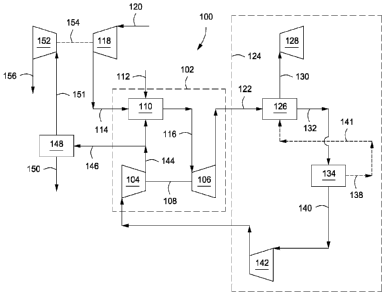
[0010] FIG. 1 depicts an integrated system for low emission power
generation and
enhanced CO2 recovery, according to one or more embodiments of the present
disclosure.
[0011] FIG. 2 depicts another integrated system for low emission power
generation and
enhanced CO2 recovery, according to one or more embodiments of the present
disclosure.
[0012] FIG. 3 depicts another integrated system for low emission power
generation and
enhanced oil recovery, according to one or more embodiments of the present
disclosure.
- 3 -
CA 02801499 2016-05-17
[0013] FIG. 4 depicts an illustrative CO2 capture system, according to
one or more
embodiments of the present disclosure.
[0014] FIG. 5 depicts another illustrative CO2 capture system, according
to one or more
embodiments of the present disclosure.
[0015] FIG. 6 depicts another illustrative CO2 capture system, according to
one or more
embodiments of the present disclosure.
[0016] FIG. 7 depicts another illustrative CO2 capture system, according
to one or more
embodiments of the present disclosure.
[0017] FIG. 8 depicts an integrated system for low emission power
generation and
nitrogen expansion for enhanced oil recovery, according to one or more
embodiments of the
present disclosure.
DETAILED DESCRIPTION OF THE DISCLOSURE
[0018] In the following detailed description section, the specific
embodiments of the
present disclosure are described in connection with preferred embodiments.
However, to
the extent that the following description is specific to a particular
embodiment or a
particular use of the present disclosure, this is intended to be for exemplary
purposes only
and simply provides a description of the exemplary embodiments. Accordingly,
the
disclosure is not limited to the specific embodiments described below, but
rather, it includes
all alternatives, modifications, and equivalents falling within the scope of
the appended
claims.
[0019] Various terms as used herein are defined below. To the extent a
term used in a
claim is not defined below, it should be given the broadest definition persons
in the
pertinent art have given that term as reflected in at least one printed
publication or issued
patent.
[0020] As used herein, the term "natural gas" refers to a multi-
component gas obtained
from a crude oil well (associated gas) or from a subterranean gas-bearing
formation
(non-associated gas). The composition and pressure of natural gas can vary
significantly.
A typical natural gas stream contains methane (CH4) as a major component, i.e.
greater than
50 mol% of the natural gas stream is methane. The natural gas stream can also
contain
- 4 -
CA 02801499 2016-05-17
ethane (C2H6), higher molecular weight hydrocarbons (e.g., C3-C20
hydrocarbons), one or
more acid gases (e.g, hydrogen sulfide, carbon dioxide), or any combination
thereof. The
natural gas can also contain minor amounts of contaminants such as water,
nitrogen, iron
sulfide, wax, crude oil, or any combination thereof.
[0021] As used herein, the term "stoichiometric combustion" refers to a
combustion
reaction having a volume of reactants comprising a fuel and an oxidizer and a
volume of
products formed by combusting the reactants where the entire volume of the
reactants is
used to form the products. As used herein, the term "substantially
stoichiometric
combustion" refers to a combustion reaction having a molar ratio of combustion
fuel to
oxygen ranging from about plus or minus 10% of the oxygen required for a
stoichiometric
ratio or more preferably from about plus or minus 5% of the oxygen required
for the
stoichiometric ratio. For example, the stoichiometric ratio of fuel to oxygen
for methane is
1:2 (CH4 + 202 > CO2 + 2H20)
. Propane will have a stoichiometric ratio of fuel to oxygen
of 1:5. Another way of measuring substantially stoichiometric combustion is as
a ratio of
oxygen supplied to oxygen required for stoichiometric combustion, such as from
about
0.9:1 to about 1.1:1, or more preferably from about 0.95:1 to about 1.05:1.
[0022] Embodiments of the presently disclosed systems and processes may
be used to
produce ultra low emission electric power and CO2 for enhanced oil recovery
(E0R) or
sequestration applications. According to embodiments disclosed herein, a
mixture of air
and fuel can be stoichiometrically or substantially stoichiometrically
combusted and mixed
with a stream of recycled exhaust gas. The stream of recycled exhaust gas,
generally
including products of combustion such as CO2, can be used as a diluent to
control or
otherwise moderate the temperature of the stoichiometric combustion and
exhaust gas
entering the succeeding expander.
[0023] By cooling the exhaust gas and condensing the water out of the
stream, a
relatively high content CO2 stream can be produced. While a portion of the
recycled
exhaust gas can be utilized for temperature moderation in the closed Brayton
cycle, a
remaining purge stream can be used for EOR applications and electric power can
be
produced with little or no S0x, NOx, or CO2 being emitted to the atmosphere.
- 5 -
CA 02801499 2016-05-17
[0024] The stoichiometric or substantially stoichiometric combustion of
the fuel
combined with a boost in the pressure or other increase in the mass flow rate
of the exhaust
gas prior to being compressed for recirculation can make the CO2 partial
pressure much
higher than in conventional gas turbine exhaust. As a result, carbon capture
in a CO2
separator can be undertaken using less energy-intensive solvents, such as
potassium
carbonate (K2CO3) or sodium carbonate (Na2CO3). The presence of oxygen (02),
S0x, and
NOx in the exhaust gas make the use of amine solvents (e.g., MEA, DEA, MDEA,
and
related solvents) difficult, even with the higher pressure and increased CO2
content, since
amine solvents can degrade in their presence. The potassium or sodium
carbonate solvents
tolerate the minimal oxygen content of the present disclosure without
degradation.
Moreover, potassium carbonate easily absorbs SOx or NON, converting it to
simple
fertilizers such as potassium sulfite (K2S03) and potassium nitrate (KNO3).
These
fertilizers can be easily discharged in an environmentally harmless manner.
[0025] Referring now to the figures, FIG. 1 depicts a schematic of an
illustrative
integrated system 100 for power generation and CO2 recovery using a combined-
cycle
arrangement, according to one or more embodiments. In at least one embodiment,
the
power generation system 100 can include a gas turbine system 102 characterized
as a
power-producing, closed Brayton cycle. The gas turbine system 102 can have a
first or
main compressor 104 coupled to an expander 106 via a shaft 108. The shaft 108
can be any
mechanical, electrical, or other power coupling, thereby allowing a portion of
the
mechanical energy generated by the expander 106 to drive the main compressor
104. In at
least one embodiment, the gas turbine system 102 can be a standard gas
turbine, where the
main compressor 104 and expander 106 form the compressor and expander ends,
respectively. In other embodiments, however, the main compressor 104 and
expander 106
can be individualized components in the system 102.
[0026] The gas turbine system 102 can also include a combustion chamber
110
configured to combust a fuel in line 112 mixed with a compressed oxidant in
line 114. In
one or more embodiments, the fuel in line 112 can include any suitable
hydrocarbon gas or
liquid, such as natural gas, methane, ethane, naphtha, butane, propane,
syngas, diesel,
kerosene, aviation fuel, coal derived fuel, bio-fuel, oxygenated hydrocarbon
feedstock, or
- 6 -
CA 02801499 2016-05-17
combinations thereof. The compressed oxidant in line 114 can be derived from a
second or
inlet compressor 118 fluidly coupled to the combustion chamber 110 and adapted
to
compress a feed oxidant 120. In one or more embodiments, the feed oxidant 120
can
include any suitable gas containing oxygen, such as air, oxygen-rich air,
oxygen-depleted
air, pure oxygen, or combinations thereof.
[0027] As will be described in more detail below, the combustion chamber
110 can also
receive a compressed recycle stream 144, including an exhaust gas primarily
having CO2
and nitrogen components. The compressed recycle stream 144 can be derived from
the
main compressor 104 and adapted to help facilitate the stoichiometric or
substantially
stoichiometric combustion of the compressed oxidant in line 114 and fuel in
line 112, and
also increase the CO2 concentration in the exhaust gas. An exhaust gas in line
116 can be
generated as a product of combustion of the fuel in line 112 and the
compressed oxidant in
line 114, in the presence of the compressed recycle stream 144. The exhaust
gas 116 is
directed to the inlet of the expander 106. In at least one embodiment, the
fuel in line 112
can be primarily natural gas, thereby generating an exhaust gas in line 116
including
volumetric portions of vaporized water, CO2, nitrogen, nitrogen oxides (N0x),
and sulfur
oxides (S0x). In some embodiments, a small portion of unburned fuel or other
compounds
may also be present in the exhaust gas in line 116 due to combustion
equilibrium
limitations. As the exhaust gas in line 116 expands through the expander 106
it generates
mechanical power to drive the main compressor 104, an electrical generator, or
other
facilities, and also produces a gaseous exhaust in line 122 having a
heightened CO2 content
resulting from the influx of the compressed recycle exhaust gas in line 144.
[0028] The power generation system 100 can also include an exhaust gas
recirculation
(EGR) system 124. In one or more embodiments, the EGR system 124 can include a
heat
recovery steam generator (HRSG) 126, or similar device, fluidly coupled to a
steam gas
turbine 128. In at least one embodiment, the combination of the HRSG 126 and
the steam
gas turbine 128 can be characterized as a closed Rankine cycle. In combination
with the
gas turbine system 102, the HRSG 126 and the steam gas turbine 128 can form
part of a
combined-cycle power generating plant, such as a natural gas combined-cycle
(NGCC)
plant. The gaseous exhaust in line 122 can be sent to the HRSG 126 in order to
generate
- 7 -
CA 02801499 2016-05-17
steam in line 130 and a cooled exhaust gas in line 132. In one embodiment, the
steam in
line 130 can be sent to the steam gas turbine 128 to generate additional
electrical power.
[0029]
The cooled exhaust gas in line 132 can be sent to any variety of apparatus
and/or
facilities in a recycle loop back to the main compressor 104.
In the illustrated
implementations, cooling units and/or booster compressors are shown and
described in
varying orders and configurations, each of which can be understood as being
adapted to
increase the mass flow rate of the cooled exhaust gas. By increasing the mass
flow rate of
the cooled exhaust gas entering the main compressor, a higher outlet pressure
may be
obtained from the main compressor.
[0030] In
some implementations, and as shown in FIG. 1, the recycle loop may
comprise at least one cooling unit 134 configured to reduce the temperature of
the cooled
exhaust gas in line 132 and generate a cooled recycle gas stream 140. In one
or more
embodiments, the cooling unit 134 can be a direct contact cooler, trim cooler,
a mechanical
refrigeration unit, or combinations thereof. The cooling unit 134 can also be
configured to
remove a portion of condensed water via a water dropout stream 138 which can,
in at least
one embodiment, be routed to the HRSG 126 via line 141 to provide a water
source for the
generation of additional steam in line 130. In one or more embodiments, the
cooled recycle
gas stream 140 can be directed to a boost compressor 142 fluidly coupled to
the cooling
unit 134. Cooling the cooled exhaust gas in line 132 in the cooling unit 134
can reduce the
power required to compress the cooled recycle gas stream 140 in the boost
compressor 142.
[0031]
The boost compressor 142 can be configured to increase the pressure of the
cooled recycle gas stream 140 before it is introduced into the main compressor
104. As
opposed to a conventional fan or blower system, the boost compressor 142
increases the
overall density of the cooled recycle gas stream 140, thereby directing an
increased mass
flow rate for the same volumetric flow to the main compressor 104. Because the
main
compressor 104 is typically volume-flow limited, directing more mass flow
through the
main compressor 104 can result in a higher discharge pressure from the main
compressor
104, thereby translating into a higher pressure ratio across the expander 106.
A higher
pressure ratio generated across the expander 106 can allow for higher inlet
temperatures
and, therefore, an increase in expander 106 power and efficiency. This can
prove
- 8 -
CA 02801499 2016-05-17
advantageous since the CO2-rich exhaust gas in line 116 generally maintains a
higher
specific heat capacity.
[0032] The main compressor 104 can be configured to compress the cooled
recycle gas
stream 140 received from the boost compressor 142 to a pressure nominally
above the
combustion chamber 110 pressure, thereby generating the compressed recycle
stream 144.
In at least one embodiment, a purge stream 146 can be tapped from the
compressed recycle
stream 144 and subsequently treated in a CO2 separator 148 to capture CO2 at
an elevated
pressure via line 150. The separated CO2 in line 150 can be used for sales,
used in another
process requiring carbon dioxide, and/or compressed and injected into a
terrestrial reservoir
for enhanced oil recovery (EOR), sequestration, or another purpose.
[0033] A residual stream 151, essentially depleted of CO2 and consisting
primarily of
nitrogen, can be derived from the CO2 separator 148. In one or more
embodiments, the
residual stream 151 can be expanded in a gas expander 152, such as a power-
producing
nitrogen expander, fluidly coupled to the CO2 separator 148. As depicted in
FIGs. 1-3, the
gas expander 152 can be optionally coupled to the inlet compressor 118 through
a common
shaft 154 or other mechanical, electrical, or other power coupling, thereby
allowing a
portion of the power generated by the gas expander 152 to drive the inlet
compressor 118.
After expansion in the gas expander 152, an exhaust gas in line 156,
consisting primarily of
nitrogen, can be vented to the atmosphere or implemented into other downstream
applications known in the art. For example, the expanded nitrogen stream can
be used in an
evaporative cooling process configured to further reduce the temperature of
the exhaust gas
as generally described in co-owned U.S. Patent Application Publication No.
2013/0091853,
entitled "Stoichiometric Combustion with Exhaust Gas Recirculation and Direct
Contact
Cooler". In at least one embodiment, the combination of the gas expander 152,
inlet
compressor 118, and CO2 separator can be characterized as an open Brayton
cycle, or the
third power producing component of the system 100.
[0034] In other embodiments, however, the gas expander 152 can be used
to provide
power to other applications, and not directly coupled to the stoichiometric
compressor 118.
For example, there may be a substantial mismatch between the power generated
by the
expander 152 and the requirements of the compressor 118. In such cases, the
expander 152
- 9 -
CA 02801499 2016-05-17
could be adapted to drive a smaller compressor (not shown) that demands less
power.
Additionally or alternatively, the expander 152 could be adapted to drive
other equipment
as appropriate. In yet other embodiments, as depicted in FIG. 8, the gas
expander 152 can
be replaced with a downstream compressor 188 configured to compress the
residual stream
151 and generate a compressed exhaust gas in line 190. In one or more
embodiments, the
compressed exhaust gas in line 190 can be suitable for injection into a
reservoir for pressure
maintenance applications. In applications where methane gas is typically
reinjected into
hydrocarbon wells to maintain well pressures, compressing the residual stream
151 may
prove advantageous. For example, the pressurized nitrogen gas in line 190 can
instead be
injected into the hydrocarbon wells and any residual methane gas can be sold
or otherwise
used as a fuel in related applications, such as providing fuel in line 112.
[0035] The EGR system 124 as described herein, especially with the
addition of the
boost compressor 142, can be implemented to achieve a higher concentration of
CO2 in the
exhaust gas of the power generation system 100, thereby allowing for more
effective CO2
separation for subsequent sequestration, pressure maintenance, or EOR
applications. For
instance, embodiments disclosed herein can effectively increase the
concentration of CO2 in
the exhaust gas stream to about 10vol% or higher. To accomplish this, the
combustion
chamber 110 can be adapted to stoichiometrically combust the incoming mixture
of fuel in
line 112 and compressed oxidant in line 114. In order to moderate the
temperature of the
stoichiometric combustion to meet expander 106 inlet temperature and component
cooling
requirements, a portion of the exhaust gas derived from the compressed recycle
stream 144
can be injected into the combustion chamber 110 as a diluent. Thus,
embodiments of the
disclosure can essentially eliminate any excess oxygen from the exhaust gas
while
simultaneously increasing its CO2 composition. As such, the gaseous exhaust in
line 122
can have less than about 3.0vol% oxygen, or less than about 1.0vol% oxygen, or
less than
about 0.1vol% oxygen, or even less than about 0.001vol% oxygen.
[0036] The specifics of exemplary operation of the system 100 will now
be discussed.
As can be appreciated, specific temperatures and pressures achieved or
experienced in the
various components of any of the embodiments disclosed herein can change
depending on,
among other factors, the purity of the oxidant used and the specific makes
and/or models of
- 10 -
CA 02801499 2016-05-17
expanders, compressors, coolers, etc. Accordingly, it will be appreciated that
the particular
data described herein is for illustrative purposes only and should not be
construed as the
only interpretation thereof In an embodiment, the inlet compressor 118 can be
configured
as a stoichiometric compressor that provides compressed oxidant in line 114 at
pressures
ranging between about 280 psia and about 300 psia. Also contemplated herein,
however, is
aeroderivative gas turbine technology, which can produce and consume pressures
of up to
about 750 psia and more.
[0037] The main compressor 104 can be configured to recycle and compress
recycled
exhaust gas into the compressed recycle stream 144 at a pressure nominally
above or at the
combustion chamber 110 pressure, and use a portion of that recycled exhaust
gas as a
diluent in the combustion chamber 110. Because amounts of diluent needed in
the
combustion chamber 110 can depend on the purity of the oxidant used for
stoichiometric
combustion or the model of expander 106, a ring of thermocouples and/or oxygen
sensors
(not shown) can be disposed associated with the combustion chamber and/or the
expander.
For example, thermocouples and/or oxygen sensors may be disposed on the outlet
of the
combustion chamber 110, on the inlet to the expander 106 and/or on the outlet
of the
expander 106. In operation, the thermocouples and sensors can be adapted to
determine the
compositions and/or temperatures of one or more streams for use in determining
the volume
of exhaust gas required as diluent to cool the products of combustion to the
required
expander inlet temperature. Additionally or alternatively, the thermocouples
and sensors
may be adapted to determine the amount of oxidant to be injected into the
combustion
chamber 110. Thus, in response to the heat requirements detected by the
thermocouples
and the oxygen levels detected by the oxygen sensors, the volumetric mass flow
of
compressed recycle gas in line 144 and/or compressed oxidant in line 114 can
be
manipulated or controlled to match the demand. The volumetric mass flow rates
may be
controlled through any suitable flow control systems, which may be in
electrical
communication with the thermocouples and/or oxygen sensors.
[0038] In at least one embodiment, a pressure drop of about 12-13 psia
can be
experienced across the combustion chamber 110 during stoichiometric
combustion.
Combustion of the fuel in line 112 and the compressed oxidant in line 114 can
generate
- 11 -
CA 02801499 2016-05-17
temperatures between about 2000 F and about 3000 F and pressures ranging
from 250
psia to about 300 psia. Because of the increased mass flow and higher specific
heat
capacity of the CO2-rich exhaust gas derived from the compressed recycle
stream 144, a
higher pressure ratio can be achieved across the expander 106, thereby
allowing for higher
inlet temperatures and increased expander 106 power.
[0039] The gaseous exhaust in line 122 exiting the expander 106 can have
a pressure at
or near ambient. In at least one embodiment, the gaseous exhaust in line 122
can have a
pressure of about 15.2 psia. The temperature of the gaseous exhaust in line
122 can range
from about 1180 F to about 1250 F before passing through the HRSG 126 to
generate
steam in line 130 and a cooled exhaust gas in line 132. The cooled exhaust gas
in line 132
can have a temperature ranging from about 190 F to about 200 F. In one or
more
embodiments, the cooling unit 134 can reduce the temperature of the cooled
exhaust gas in
line 132 thereby generating the cooled recycle gas stream 140 having a
temperature
between about 32 F and 120 F, depending primarily on wet bulb temperatures
in specific
locations and during specific seasons.
[0040] According to one or more embodiments, the boost compressor 142
can be
configured to elevate the pressure of the cooled recycle gas stream 140 to a
pressure
ranging from about 17.1 psia to about 21 psia. Additionally or alternatively,
the mass flow
rate of the cooled recycle gas stream may be increased through other means,
such as
cooling. As a result, the main compressor 104 receives and compresses a
recycled exhaust
gas with a higher density and increased mass flow, thereby allowing for a
substantially
higher discharge pressure while maintaining the same or similar pressure
ratio. In at least
one embodiment, the temperature of the compressed recycle stream 144
discharged from
the main compressor 104 can be about 800 F, with a pressure of around 280
psia.
[0041] The following table provides testing results and performance
estimations based
on combined-cycle gas turbines, with and without the added benefit of a boost
compressor
142, as described herein.
- 12-
CA 02801499 2016-05-17
TABLE 1
Triple -Cycle Performance Comparison
Recirc. Cycle Recirc. Cycle w/
Power (MW) w/o Boost Boost
Compressor Compressor
Gas Turbine Expander Power 1055 1150
Main Compressor 538 542
Fan or Boost Compressor 13 27
Inlet Compressor 283 315
Total Compression Power 835 883
Net Gas Turbine Power 216 261
Steam Turbine Net Power 395 407
Standard Machinery Net Power 611 668
Aux. Losses 13 15
Nitrogen Expander Power 156 181
Combined Cycle Power 598 653
Efficiency
Fuel Rate (mBTU/hr) 5947 6322
Heat Rate (BTU/kWh) 9949 9680
Combined Cycle Eff. (%lhv) 34.3 35.2
CO2 Purge Pressure (psia) 280 308
[0042] As should be apparent from Table 1, embodiments including a boost
compressor
142 can result in an increase in expander 106 power (i.e., "Gas Turbine
Expander Power")
due to the increase in pressure ratios. Although the power demand for the main
compressor
104 can increase, its increase is more than offset by the increase in power
output of the
expander 106, thereby resulting in an overall thermodynamic performance
efficiency
improvement of around 1% lhv (lower heated value).
[0043] Moreover, the addition of the boost compressor 142 or cooling in
the exhaust
gas recirculation system can also increase the power output of the nitrogen
expander 152
and the CO2 purge pressure in the purge stream 146 line. An increase in purge
pressure of
the purge stream 146 can lead to improved solvent treating performance in the
CO2
separator 148 due to the higher CO2 partial pressure. Such improvements can
include, but
are not limited to, a reduction in overall capital expenditures in the form of
reduced
equipment size for the solvent extraction process.
[0044] Referring now to FIG. 2, depicted is an alternative embodiment of
the power
generation system 100 of FIG. 1, embodied and described as system 200. As
such, FIG. 2
- 13 -
CA 02801499 2016-05-17
may be best understood with reference to FIG. 1. Similar to the system 100 of
FIG. 1, the
system 200 of FIG. 2 includes a gas turbine system 102 coupled to or otherwise
supported
by an exhaust gas recirculation (EGR) system 124. The EGR system 124 in FIG.
2,
however, can include an embodiment where the boost compressor 142 follows or
may
otherwise be fluidly coupled to the HRSG 126. As such, the cooled exhaust gas
in line 132
can be compressed in the boost compressor 142 before being reduced in
temperature in the
cooling unit 134. Thus, the cooling unit 134 can serve as an aftercooler
adapted to remove
the heat of compression generated by the boost compressor 142. As with
previously
disclosed embodiments, the water dropout stream 138 may or may not be routed
to the
HRSG 126 to generate additional steam in line 130.
[0045] The cooled recycle gas stream 140 can then be directed to the
main compressor
104 where it is further compressed, as discussed above, thereby generating the
compressed
recycle stream 144. As can be appreciated, cooling the cooled exhaust gas in
line 132 in
the cooling unit 134 after compression in the boost compressor 142 can reduce
the amount
of power required to compress the cooled recycle gas stream 140 to a
predetermined
pressure in the succeeding main compressor 104.
[0046] FIG. 3 depicts another embodiment of the low emission power
generation
system 100 of FIG. 1, embodied as system 300. As such, FIG. 3 may be best
understood
with reference to FIGs. 1 and 2. Similar to the systems 100, 200 described in
FIGs. 1 and 2,
respectively, the system 300 includes a gas turbine system 102 supported by or
otherwise
coupled to an EGR system 124. The EGR system 124 in FIG. 3, however, can
include a
first cooling unit 134 and a second cooling unit 136, having the boost
compressor 142
fluidly coupled therebetween. As with previous embodiments, each cooling unit
134, 136
can be a direct contact cooler, trim cooler, or the like, as known in the art.
[0047] In one or more embodiments, the cooled exhaust gas in line 132
discharged from
the HRSG 126 can be sent to the first cooling unit 134 to produce a condensed
water
dropout stream 138 and a cooled recycle gas stream 140. The cooled recycle gas
stream
140 can be directed to the boost compressor 142 in order to boost the pressure
of the cooled
recycle gas stream 140, and then direct it to the second cooling unit 136. The
second
cooling unit 136 can serve as an aftercooler adapted to remove the heat of
compression
- 14 -
CA 02801499 2016-05-17
generated by the boost compressor 142, and also remove additional condensed
water via a
water dropout stream 143. In one or more embodiments, each water dropout
stream 138,
143 may or may not be routed to the HRSG 126 to generate additional steam in
line 130.
[0048] The cooled recycle gas stream 140 can then be introduced into the
main
compressor 104 to generate the compressed recycle stream 144 nominally above
or at the
combustion chamber 110 pressure. As can be appreciated, cooling the cooled
exhaust gas
in line 132 in the first cooling unit 134 can reduce the amount of power
required to
compress the cooled recycle gas stream 140 in the boost compressor 142.
Moreover,
further cooling exhaust in the second cooling unit 136 can reduce the amount
of power
required to compress the cooled recycle gas stream 140 to a predetermined
pressure in the
succeeding main compressor 104.
[0049] The combination of stoichiometric combustion in the combustion
chamber 110
and water removal through the cooling units 134, 136, allows the CO2 content
in the
exhaust gas (e.g., streams 122, 132, 140, and/or 144) to accumulate to about
10vol% or
higher, which is higher than exhaust gases in conventional combined-cycle
systems. These
effects, plus the impact of higher mass flow rates resulting from the
implementation and
effect of the boost compressor 142 and/or cooling units, make the CO2 partial
pressure
much higher than conventional gas turbine exhaust. Consequently, this allows
for carbon
capture in the CO2 separator 148 using less energy-intensive solvents, such as
potassium
carbonate (K2CO3) solvent technology.
[0050] The presence of oxygen (02), S0x, and NOx make the use of amine
solvents
(e.g., MEA, DEA, MDEA, and related solvents) difficult, even with the higher
pressure and
increased CO2 content, since these gases can cause amine degradation.
Potassium
carbonate, however, is non-reactive and immune to any effects of oxygen.
Although the
reaction undertaken in the combustion chamber 110 is intended to be
stoichiometric, a
fraction of oxygen may nonetheless be present in the purge stream 146 due to
combustion
equilibrium limitations. While the use of MEA solvents in this application
would require
significant solvent reclamation and complicated disposal, the use of potassium
carbonate
solvents eliminates oxygen-based solvent degradation.
- 15-
CA 02801499 2016-05-17
[0051]
Potassium carbonate easily absorbs SOx or NO in the exhaust gas, converting
these compounds to simple fertilizers, such as potassium sulfite (K2S03) and
potassium
nitrate (KNO3). In particular, SO2, SO3, and NO2 all form fairly strong acids
in water, much
stronger than CO2. Thus, they will be preferentially absorbed in the solvent
solution, but
will become heat stable salts (HSS) and will not be removed by regeneration.
On the other
hand, NO and N20 have low solubility and are more difficult to absorb than
NO2, and tend
to occur at lower concentrations. As simple fertilizers, the potassium sulfite
and potassium
nitrate can be easily discharged in an environmentally harmless manner, so
long as no other
toxic compounds, such as corrosion inhibitors, activators, etc., are added to
the solvent
system. When the sulfate and nitrate compounds are removed, potassium
hydroxide (KOH)
can be added for solvent makeup. Since potassium hydroxide is a fairly
inexpensive
chemical, this can be accomplished rather economically.
[0052]
Referring to FIG. 4, depicted is an exemplary embodiment of a CO2 separation
system 400 that can employ potassium carbonate solvent technology as described
herein.
The CO2 separation system 400 can be or form at least a portion of the CO2
separator 148,
as generally described herein with reference to FIGs. 1-3. In one or more
embodiments, the
system 400 can be configured to receive the purge stream 146 tapped from the
compressed
recycle stream 144 (FIGs. 1-3) at a temperature of around 800 F and a
pressures of around
270 psia to about 280 psia.
[0053] The
purge stream 146, containing primarily nitrogen, CO2, and excess
combustion water, can be cooled in a heat exchanger 402 to a temperature
ranging from
about 250 F to about 300 F, thereby generating a cooled purge stream in line
404. In an
embodiment, the heat exchanger 402 can generate steam to be integrated with
the steam
stream 130 from the HRSG 126 (FIGs. 1-3). Extracting CO2 from the purge stream
146 in
the CO2 separation system 400 generates a nitrogen-rich residual stream 151 at
or near the
elevated pressure of the purge stream 146 and at a temperature of about 150
F. In at least
one embodiment, the heat exchanger 402 can be a cross-exchange heat exchanger
fluidly
coupled to the residual stream 151 and configured to extract the heat energy
associated with
cooling the purge stream 146 in order to re-heat the residual stream 151. Once
reheated, the
residual stream 151, consisting primarily of a nitrogen vapor having a
temperature of about
- 16-
CA 02801499 2016-05-17
750 F and a pressure of around 270-280 psia, can be subsequently expanded to
generate
mechanical power, as generally described above.
[0054] The cooled purge stream in line 404 can be directed to an
absorber column 406
where a solvent from line 408 is circulated, and the residual stream 151 is
simultaneously
discharged overhead for further downstream processing. In one embodiment, the
solvent is
a water-based salt solution of potassium carbonate. When compared to competing
solvents,
such as MEA, the potassium carbonate solvent is quite temperature-tolerant. As
a result,
the cooling of the purge stream 146 can be minimized, as needed, and a higher
temperature
purge stream 146 can be allowed to enter the absorber column 406 without
raising thermal
degradation concerns. Accordingly, the degree of cooling of the purge stream
146 can be
modified to match process heat requirements, rather than cooling to avoid
thermal
degradation.
[0055] As CO2 is absorbed by the potassium carbonate in the absorber
column 406, it
reacts with water to form carbonic acid (H2CO3), and then bicarbonate (HCO3-).
The acidic
part of the carbonic acid (H+) can react with the carbonate ion (CO3-2) to
form an additional
bicarbonate ion. Thus, the overall reaction can be as follows:
CO2 + H20 + K2C034¨ 2KHCO3
[0056] As a result, a rich, bicarbonate solvent can be discharged from
the bottom of the
absorber column 406 via line 410 and directed to a regeneration column 412. In
one
embodiment, a first or intermediate valve 414 disposed in the line 410 can be
configured to
flash the bicarbonate solvent to a lower, near-atmospheric pressure before
introduction to
the regeneration column 412. In at least one embodiment, the first valve 414
can be a
hydraulic turbine configured to generate extra power.
[0057] In at least one embodiment, the regeneration column 412 can
operate at
temperatures exceeding the normal boiling point of water. For example, the
regeneration
column 412 can operate at a temperature range from about 220 F, about 230 F,
or about
240 F to about 280 F, about 290 F, or about 300 F. The regeneration column
412 can
operate at pressures ranging from about 0 psig to about 10 psig. In at least
one
embodiment, the regeneration column 412 can be configured to operate at a
pressure of
about 3 psig. The regeneration column 412 can be configured to use steam
circulating
- 17 -
CA 02801499 2016-05-17
therein to boil the bicarbonate solvent and reverse the reaction undertaken in
the absorber
column 406, thereby yielding a regenerated, lean potassium carbonate solvent
suitable for
recirculation via line 416 below. In at least one embodiment, an in-line pump
418, or the
like, can drive at least a portion of the lean potassium carbonate solvent via
line 420 back to
the absorber column 406.
[0058] En route to the absorber column 406, a portion of the lean
potassium carbonate
solvent can be removed as a heat stable salt (HSS) via line 423. As described
above,
illustrative HSSs extracted via line 423 can include compound fertilizers such
as, but not
limited to, potassium sulfite and/or potassium nitrate. In order to make up
for the loss of
potassium carbonate content removed via line 423, and to maintain overall
solution
strength, a stream of potassium hydroxide can be subsequently added via line
425. In one
or more embodiments, the potassium hydroxide serves as a solvent makeup. The
lean
potassium carbonate solvent in line 420 can then be optionally directed
through a first
cooling unit 422. In one or more embodiments, the first cooling unit 422 can
be, for
example, an air cooler or radiator-type heat exchanger, configured to reduce
the
temperature of the solvent. If used, the first cooling unit 422 can be
configured to reduce
the temperature of the lean potassium carbonate solvent to temperatures
ranging between
about 230 F and about 60 F. As can be appreciated, in at least one
embodiment the HSSs
can alternatively be removed as fertilizers subsequent to the first cooling
unit 422, as well
as the addition of potassium hydroxide.
[0059] In order to generate the steam circulating in the regeneration
column 412 and
maintain the required heat of regeneration, at least a portion of the lean
potassium carbonate
solvent in line 416 can be directed to a reboiler 419 via line 417. The
reboiler 419 can be
configured to increase the temperature of the lean potassium carbonate solvent
in line 417,
and return a heated regenerated potassium carbonate solvent back to the
regeneration
column via line 421. In at least one embodiment, the reboiler 419 can be
supplied with heat
from the HRSG 126 (FIGs. 1-3). In other embodiments, however, the reboiler 419
can be
supplied with heat from the discharge of the steam gas turbine 128 (FIGs. 1-
3).
[0060] The water included in the purge stream 146 can condense into the
solvent
solution in the absorber column 406, and subsequently boil out in the
regeneration column
- 18-
CA 02801499 2016-05-17
412. Consequently, the regeneration column 412 can further discharge CO2 vapor
and any
residual water via overhead line 424. In at least one embodiment, the CO2
vapor and
residual water can be directed through a second cooling unit 426, such as an
air cooler or
radiator-type heat exchanger, before being introduced into a condenser 428.
The condenser
428 can be configured to separate the residual water from any recovered CO2
and direct the
separated water into line 430 below while feeding the recovered CO2 into line
150
overhead. As can be appreciated, line 150 can be the same line 150 as
described above
with reference to FIGs. 1-3. In at least one embodiment, the separated CO2 in
line 150 can
be subsequently compressed for applications such as CO2 sequestration,
enhanced oil
recovery, CO2 sales, carbon capture, and/or combinations thereof.
100611 In one embodiment, at least a portion of the separated water in
line 430 can be
recirculated back into the regeneration column 412 via line 434 using a pump
432 to allow
the balance of water in the system to be maintained constant. Water is
constantly
introduced into the solvent via stream 404, and subsequently removed via lines
436, 150,
and 151. In order to maintain solvent conditions and strength, the water must
remain in
balance within the system 400. Accordingly, the water recirculated in line 434
can allow
water to be returned so that steam raised in line 421 can be controlled
independently of this
water balance. In other words, this recirculated water can be used as
feedwater for the
generation of steam in the regeneration column 412 or to raise low pressure
steam from
feed cooling. In other embodiments, a portion of the residual water in line
430 can be
disposed of as fresh process water via line 436. For example, although
containing a portion
of dissolved CO2, the water in line 436 can be used for irrigation water,
treated to be used
for boiler feed water, and/or other process water.
100621 Referring now to FIG. 5, depicted is another illustrative
embodiment of a CO2
separation system 500, similar in some respects to the system 400 of FIG. 4.
As such, the
entire system 500 will not be described in detail but may be best understood
with reference
to FIG. 4. Whereas the system 400 of FIG. 4 could be characterized as a single-
stage
potassium carbonate process, the system 500 of FIG. 5 can be characterized, in
at least one
embodiment, as a two-stage potassium carbonate process. As depicted, the CO2
separation
system 500 can include a "semi-lean" solvent recirculation loop, wherein a
portion of the
- 19 -
CA 02801499 2016-05-17
solvent can be withdrawn from the regeneration column 412 via line 502 prior
to complete
regeneration. In at least one embodiment, the portion of the solvent withdrawn
via line 502
can be about 50% or more of the total solvent volume circulating through the
regeneration
column 412. The balance of the solvent solution remaining in the regeneration
column 412
can be fully regenerated, as described above, and discharged via line 416
therebelow.
[0063] A pump 504 disposed within line 502 can direct the semi-lean
solvent solution
to the absorber column 406. In one embodiment, the semi-lean solvent solution
can be fed
low 506 into the absorber column 406. Being only partially regenerated, the
semi-lean
solvent in line 502 is not able to absorb CO2 from the lower concentration
gases higher in
the absorber column 406. Instead, it can be fed into the absorber column 406
where it can
absorb the maximum amount of CO2, and not dilute the fully lean solvent
entering the
absorber column 406 via line 408.
[0064] This variation in the system 500 can require a higher solvent
circulation flowrate
than the system 400 of FIG. 4, but can demand less external heat energy to
remove the CO2.
With this improved thermal efficiency, the system 500 can require less
reboiler 419 heat
duty than is contained in the purge stream 146. In other words, the heat of
the incoming
purge stream 146 may be able to supply all the reboiler 419 heat requirements.
Consequently, if the residual stream 151 is injected for EOR, the system 500
can be
thermally self-sufficient and require no make-up heat from the power turbine
HRSG 126.
[0065] Referring now to FIG. 6, depicted is another exemplary embodiment of
a CO2
separation system 600, similar in some respects to the systems 400, 500 of
FIGs. 4 and 5,
respectively. As such, the entire system 600 will not be described in detail
but may be best
understood with reference to FIGs. 4 and 5. As depicted, the rich, bicarbonate
solvent can
be discharged from the bottom of the absorber column 406 via line 410 and
reduced in
pressure using a first valve 602 before being introduced into a separator 604.
In one
embodiment, the first valve 602 can be configured to reduce the pressure of
the bicarbonate
solvent from the purge stream 146 pressure (e.g., between about 270 ¨ 280
psia) to an
intermediate pressure level. In one or more embodiments, the intermediate
pressure level
can range from about 20 psia to about 50 psia.
- 20 -
CA 02801499 2016-05-17
[0066] The separator 604 can be configured to receive the reduced-
pressure solution
and remove at least a portion of CO2 via overhead line 606. In one or more
embodiments,
the removed CO2 in line 606 can be cooled in a cooling unit 608, and
subsequently fed into
a downstream compression system 607. In one or more embodiments, the cooling
unit 608
can be a direct contact cooler, trim cooler, a mechanical refrigeration unit,
or combinations
thereof Since the removed portion of CO2 in line 606 is at an elevated
pressure, albeit an
intermediate pressure between the pressure of the purge stream 146 and
atmospheric, it can
be injected into an intermediate stage of the downstream compression system
607, thereby
reducing the required compression load on the compression system 607.
[0067] The balance of the CO2 and bicarbonate solvent remaining in the
separator 604
can be discharged from the separator 604 via line 610 below and flashed to a
lower, near-
atmospheric pressure in stream 611 using a second valve 612 before being
directed into the
regeneration column 412. In several embodiments of the system 600, complete
solvent
regeneration can then take place as described above with reference to either
system 400 or
system 500 as depicted in FIGs. 4 or 5, respectively. For instance, as
described above a
separated portion of CO2 can be extracted from the condenser 428 via line 150
at or near
atmospheric pressure and directed to a first compression stage of the
downstream
compression system 607. Consequently, the downstream compression system 607
can
receive at least two feed streams substantially including captured CO2; one
feed stream
having high pressure CO2 in line 606 that is injected into an intermediate
compression
stage, and a second feed stream having low pressure CO2 in line 150 and
injected at the first
compression stage. As can be appreciated, such an arrangement can reduce the
power
demand for CO2 compression in preparation for EOR or sequestration at
virtually no
increase in regenerator column 412 thermal load.
[0068] At least one benefit derived from the system 600 is the ability to
produce a pure
or nearly pure CO2 stream from the regeneration column 412. The contaminants
present in
the CO2 stream in line 410 can include water and some volatile gases (e.g.,
N2, CO, Ar,
etc.) dissolved into the circulating solvent. The system 600 can be adapted to
remove
essentially all of these volatile gases, leaving the regeneration column 412
overhead stream
424 with only high purity CO2 and water. In one or more embodiments, the CO2
- 21 -
CA 02801499 2016-05-17
concentration in the overhead line 424 can be around 2/3 of the total CO2 flow
in the
system 600. Once separated from the water, a portion of the CO2 in line 150
can be
directed into a purge line 614 and captured for non-EOR uses, such as chemical
feedstock,
food production, etc.
[0069] As
can be appreciated, embodiments and features disclosed with reference to
FIGs. 5-6 can be combined without departing from the disclosure. Accordingly,
the
following table and supplemental information provides illustrative process
data for a
combination of embodiments and/or features described above. The solvent stream
and gas
stream reference numerals shown in the table can be referred to in FIGs. 5-6.
- 22 -
CA 02801499 2016-05-17
TABLE 2¨ Process Data
Solvent Stream Number 408 506 410 611 434
Temperature - F 120 219.81 230.8 208.3 112
Pressure - psia 276.2 277.2 276.2 17.7 16.7
Flowrate (klb/hr) 5,079 14,036 19,988 19,701 220
Flowrate (USGPM) 8,937 23,757 33,795 650,017
443
Equiv. wt % K2CO3 in solution 35.60% 31.80% 31.40% 31.80%
0.00%
% K2CO3 reacted to KHCO3 , 7.80% 33.50% 65.60% 54.70% N /
A
Stream pH 9.6 8.6 8.1 8.5 4.1
Gas Stream Number 146 151 606 424
Temperature - F 803.2 141.62 120 112
Pressure - psia 283.2 276.2 28 16.7
Flowrate (lbmole/hr) 158,729 132,137 5,497 10,969
Flowrate (MMSCFD) 1,446 1,203 50 100
H20 Mole % 7.97% 0.98% 6.14% 8.17%
CO, Mole % 10.36% 1.00% 91.69% 91.83%
Mole % Other (N2+02+Ar+co+142) 81.67% 98.02% 2.17% 0.00%
Heat Required:
Feed Gas Cross-exchanger 402 629 MBTU/hr Total:
Regenerator Reboiler 419 586 MBTU/hr (20 psig steam) 586 MBTU/hr
Heat Rejected:
Cooling Unit 608 114 MBTU/hr
Condenser 428 381 MBTU/hr
Cooling Unit 422 478 MBTU/hr Total:
CO2 Compressor Coolers (total) 216 MBTU/hr 1189 MBTU/hr
Power Loads:
Gas Expander 152 (FIGs. 1-3) 222,414 hp Produced
Lean Solvent Pump 418 2,035 hp Consumed
Semi-Lean Solvent Pump 504 5,532 hp Consumed
CO2 Compressor (total) 49,450 hp Consumed Total:
Net Power Produced/Consumed 165,397 hp Consumed 165,397hp
[0070] Referring now to FIG. 7, depicted is another exemplary embodiment
of a CO2
separation system 700. Since the system 700 is similar in some respects to the
systems 400
and 500 described above, the entire system 700 will not be described in detail
but may be best
understood with reference to FIGs. 4 and 5. The system 700 can prove
particularly
- 23 -
CA 02801499 2016-05-17
advantageous in embodiments where the residual stream 151 and captured CO2 in
line 150
are to be reinjected in EOR applications. As will be described below, the
system 700 can be
configured to allow superior integration of the cooling of purge stream 146 in
conjunction
with the process heat requirements in the regeneration column 412 and reboiler
419.
[0071] Since the
residual stream 151 in the system 700 may be subsequently
compressed for EOR, the heat exchanger 402 is not necessarily cross-exchanged
with the
residual stream 151, but instead its heat energy can be available for other
uses. For
example, in one or more embodiments, the heat exchanger 402 can be configured
to receive
at least a portion of the recovered combustion water, or wastewater from line
436 to
generate a low pressure steam in line 702. The resulting steam in line 702 can
have a
pressure of about 50 psig or higher and can be split into lines 702a and 702b
and used as
motive power gas for one or more eductors 704a and 704b. While two lines 702a
and 702b
and two eductors 704a and 704b are shown in FIG. 7, it will be appreciated
that there can
be more or less, without departing from the scope of the disclosure.
[0072] In one
embodiment, the eductors 704a and 704b can be configured as steam
ejectors adapted to reduce the pressure on the lean potassium carbonate
solvent discharged
into line 416 from the regeneration column 412. To accomplish this, the lean
solvent in line
416 can be directed into one or more mixing chambers 706a and 706b arranged in
series
and fluidly coupled to the eductors 704a and 704b, respectively. In one
embodiment, the
first mixing chamber 706a can feed the second mixing chamber 706b for further
processing. In other embodiments, however, the mixing chambers 706a and 706b
may be
arranged in parallel, without departing from the scope of the disclosure.
[0073] In
operation, the eductors 704a and 704b can be adapted to accelerate the steam
in line 702 to create a low-pressure zone at or near vacuum conditions
configured to
flash-boil the lean solvent in the mixing chambers 706a and 706b. Boiling the
lean solvent
can release additional water and CO2 not recovered via overhead line 424 and
draw the
resulting gaseous effluent into lines 708a and 708b. The resulting effluent in
lines 708a
and 708b, can be injected into the regeneration column 412 to remove and
capture the
excess CO2 via overhead line 424. Because of its steam content, the effluent
can also serve
as stripping steam, thereby supplementing or entirely replacing at least some
of the
- 24 -
CA 02801499 2016-05-17
regenerative boiling heat duty generally supplied by the reboiler 419.
Accordingly, the
system 700 can allow some of the heat held in the lean solvent to drive the
vapor flow in
the mixing chambers 706a and 706b, thereby reducing the net heat required for
solvent
regeneration and the overall size of the reboiler 419.
[0074] Flash-boiling the additional water and CO2 in the mixing chambers
706a and
706b can also simultaneously cool the remaining lean solvent by reducing its
pressure from
about 3 psig to about 10 psig vacuum. In one or more embodiments, the
temperature of the
lean solvent can be reduced from about 240 F, about 230 F, or about 220 F
to about 210
F, about 200 F, or about 190 F. The cooled lean solvent can then be
discharged from the
mixing chamber 706b via line 710 and then directed to the in-line pump 418
which, as
described above, can drive the solvent via line 420 back to the absorber
column 406. Since
the temperature of the lean solvent can be cooled in the mixing chambers 706a
and 706b,
the size of the cooling unit 422 can be reduced.
[0075] Because the low pressure steam provided in lines 702a and 702b to
eductors
704a and 704b, respectively, is injected into the regeneration column 412, it
can result in
the consumption of at least a portion of the feedwater derived from the
separated water in
line 434. Accordingly, any additional water can be recovered from the
regeneration column
412 via the overhead line 424 as additional wastewater. As a result, excess
water can be
continually building up in the system 700 and may be extracted via the
wastewater line 436.
As can be appreciated, the water reflux rate can be varied to maintain the
solvent water
balance, or the potassium carbonate solution strength.
[0076] As can be appreciated, embodiments and features disclosed with
reference to
FIGs. 5-7 can be combined without departing from the disclosure. Accordingly,
the
following table and supplemental information provides illustrative process
data for an
exemplary combination of embodiments and/or features described above. The
solvent stream
and gas stream reference numerals shown in the table can be referred to in
FIGs. 5-7.
- 25 -
CA 02801499 2016-05-17
TABLE 3¨ Process Data
Solvent Stream Number 408 506 410 611 416 710
434
Temperature - F 126 225.7 239.1 212 227.7 192.5
112
Pressure - psia 276.2 277.2 276.2 17.7 17.7 8.7
16.7
Flowrate (klb/hr) 4,966 11,380 17,210 16,866
5,142 4,966 64
Flowrate (USGPM) 8,749 20,267 29,088 642,184 8,643
8,219 129
Equiv. wt % K2CO3 in
35.10% 32.80% 31.80% 32.50% 33.90% 35.10% 0.00%
solution
% K2CO3 reacted to KHCO3 5.20% 20.50% 63.70% 51.20% 5.90%
5.20% N/A
Stream pH 9.7 8.9 8.1 8.5 9.4 9.5
4.1
Gas Stream Number 436 151 606 150 708a ,b 702a,b
Temperature - F 803.2 152.6 126 112 286.6 297.8
Pressure - psia 283.2 276.2 28 16.7 17.7 64.7
Flowrate (lbmole/hr) 158,729 132,582 5,387 11,114 34,169
24,457
Flowrate (MMSCFD) 1,446 1,208 49 101 311 223
H20 Mole % 7.97% 1.30% 7.24% 8.17%
99.86% 100%
CO2 Mole % 10.36% 1.00% 90.83% 91.83% 0.14%
0%
Mole % Other
(N2+02+Ar+CO+142) 81.67% 97.70% 1.93% 0.00% 0.00%
0%
Heat Required: None (feed gas supplies all heat)
Heat Rejected:
Cooling Unit 608 139 MBTU/hr
Condenser 428 611 MBTU/hr
Cooling Unit 422 271 MBTU/hr Total:
CO2 Compressor Coolers
(total) 217 MBTU/hr 1,273 MBTU/hr
Power Loads:
Lean Solvent Pump 418 2,047 hp Consumed
Semi-Lean Solvent Pump
504 4,473 hp Consumed Total:
55,992
CO2 Compressor (total) 49,473 hp Consumed hp
Material Export
Inert Gas (primarily N2) 151 1,208 Mscfd @ 276.2 psia
[0077]
While the present disclosure may be susceptible to various modifications and
alternative forms, the exemplary embodiments discussed above have been shown
only by
way of example. However, it should again be understood that the disclosure is
not intended
to be limited to the particular embodiments disclosed herein. Indeed, the
present disclosure
includes all alternatives, modifications, and equivalents falling within the
true spirit and
scope of the appended claims.
- 26 -