Note: Descriptions are shown in the official language in which they were submitted.
1
SYSTEM AND METHOD FOR DETECTING AMYLOID PROTEINS
10
BACKGROUND OF THE INVENTION
It is always desirable to detect diseases early in their progress. Early
detection enables early treatment which has generally been proven to yield a
higher
success rate in treating various diseases, It has been discovered that
analyzing
peoples' eyes, and in particular the lenses of the eyes, can yield indications
of
various types of diseases. For example, researchers have found p-amyloid
peptides
and aggregates thereof in the supranucleus of the lens of the eyes of
Alzheimer's
disease [AD] victims. See U.S. Patent No. 7,297,326 of Goldstein et al. Since
the
supranucleus is only a fraction of a millimeter thick, measurements obtained
from
this region of the crystalline lens need to be accurate in location, specific
in
information and fast in acquisition. This is especially true because the human
eye is
in almost constant motion even when a patient is fixating on an illuminated
target.
It has been shown that the presence of, or an increase in, the amount of [3-
amyloid peptides and aggregates thereof in the supranuclear and/or cortical
lens
regions of a test mammal's eye compared to a normal control value indicates
that the
CA 2807683 2018-09-25
CA 02807683 2013-02-06
WO 2012/024188 PCT/US2011/047628
- 2 -
test mammal is suffering from, or is at risk of developing, a
neurodegenerativc
disease such as an amyloidogenic disorder.
There is an ongoing need for systems and methods for permitting early
detection of amyloidogenic disorders.
SUMMARY OF THE INVENTION
In accordance with an embodiment of the invention, there is provided a
method for detecting in an eye of a mammal an amyloid protein, such as an
amyloid
protein comprising an aggregate. In some embodiments, detection of the amyloid
protein is indicative of an amyloidogenic disorder. The method comprises
illuminating the eye with a light source having at least one of a wavelength
property,
a polarization property or a combination thereof, each appropriate to produce
fluorescence in at least an amyloid-binding compound when the amyloid-binding
compound is bound to the amyloid protein, the amyloid-binding compound having
been introduced to the eye and specifically binding to the amyloid protein
indicative
of the amyloidogenic disorder; receiving light including fluorescence produced
as a
result of the illuminating the eye; and determining a time decay rate of
fluorescence
for at least the fluorescence produced by the amyloid-binding compound bound
to
the amyloid protein, the determining permitting distinguishing of the presence
of the
amyloid-binding compound bound to the amyloid protein in the eye based on at
least
the time decay rate.
In further, related embodiments, the method may further comprise
determining an intensity of fluorescence for at least the fluorescence
produced by
the amyloid-binding compound bound to the amyloid protein. A quantity of the
amyloid-binding compound bound to the amyloid protein may be determined, based
on at least one of the intensity and the time decay rate. The method may
further
comprise determining a location of an ocular interface such as a lens capsule
of the
eye based on an increase in a fluorescent signal due to natural fluorescence
emitted
from tissues of the eye. At least one region of the eye may be sampled using
illumination by the light source, the sampling comprising performing at least
one of
a measure of the entire region or a sampling of different locations within the
region
CA 02807683 2013-02-06
WO 2012/024188 PCT/US2011/047628
- 3 -
or regions using illumination by the light source, the sampling of different
locations
comprising illuminating at least one point, plane and/or volume within the
eye. The
sampling may comprise sampling different locations across more than one region
of
the eye. For example. planar scans of the eye may be performed using the light
source, in successive planes along a perpendicular axis extending depthwise
into the
eye. A location of a supranucleus of the eye may be determined based on (i) a
distance away from a specific anatomical structure such as an interface of the
lens
capsule of the eye or corneal interface or (ii) a detection of a change
(slope) in
intensity measurement. The distinguishing the presence of the amyloid-binding
compound bound to the amyloid protein may comprise distinguishing the amyloid-
binding compound bound to the amyloid protein from background autofluorescence
of eye tissues and autofluorescenee of other non-specific particles as well as
unbound imaging agent. The method may comprise distinguishing at least one of
a
presence and a quantity of more than one of the following: the amyloid-binding
compound; the amyloid-binding compound bound to the amyloid protein; and the
amyloid protein. The amyloid protein may comprise an aggregate or a pre-
amyloid
protein aggregate (including dimers, trimers or higher order oligomers of the
peptides AP 1-42 and/or Al3 1-40). For example, the amyloid protein may
comprise
beta-amyloid. The amyloidogenic disorder may comprise Alzheimer's disease.
In further, related embodiments, the amyloid-binding compound may
comprise a molecular rotor, Chrysamine and/or a Chrysamine derivative, a Congo
red and/or Congo red derivative amyloid-binding compound; a Chrysamine G or
Chyrsamine G derivative amyloid-binding compound; a Thioflavin T or Thioflavin
T derivative amyloid-binding compound; and a Thioflavin S or Thioflavin S
derivative amyloid-binding compound. The method may comprise distinguishing at
least the presence of the amyloid protein based only on detection of
fluorescence.
The method may further comprise determining the average number of photons with
a specific decay rate in a certain area of the eye. A rate of delivery of the
amyloid-
binding compound to the eye, a spatial distribution of amyloid-binding
compound
delivered to the eye, and/or a gradient of concentration of the amyloid-
binding
compound at an interface of the cornea of the eye may be determined based on
CA 02807683 2013-02-06
WO 2012/024188 PCT/US2011/047628
- 4 -
detected fluorescence. Further, a spatial distribution of the amyloid-binding
compound and/or a temporal distribution of the amyloid-binding compound in the
aqueous humor of the eye may be determined based on detected fluorescence.
The method may further comprise detaimining at least one dimension of an
anatomical structure or substructure of the eye based on natural fluorescence
excitation of at least a portion of the anatomical structure or substructure.
Determining the at least one dimension may comprise at least one of
determining a
thickness of the structure or substructure, determining a shape of the
structure or
substructure, and deteiniining a distance between one or more structure or
substructures of the eye. For example, determining the at least one dimension
may
include determining a corneal thickness, corneal shape, aqueous humor depth,
lens
shape or lens thickness, or determining an internal measurement within the
lens or
other structure or substructure of the eye, such as a distance from the
surface of the
lens to the cortex or supranucleus or nucleus. The method may further comprise
detecting fluorescence produced by the eye using a photodetector device, such
as at
least one of a photodiode, a photomultiplier, a charge-coupled device (CCD)
and an
intensified charge-coupled device (ICCD); for example a fast avalanche
photodiode
detector. The method may comprise performing a time correlation single photon
counting of fluorescence produced by the eye. The time correlation single
photon
counting may comprise pulsing the light source and determining the time decay
rate
of fluorescence based on a distribution of photon counts as a function of time
channel units.
In further, related embodiments, the method may comprise scanning within
the eye to determine excited natural fluorescence and thereby to determine at
least
one region of interest in the eye; and sampling the at least one region of
interest in
the eye using illumination by the light source, the sampling comprising
performing
at least one of a measure of at least one entire region of the at least one
region or a
sampling of different locations within the at least one region using
illumination by
the light source, the sampling of different locations comprising illuminating
at least
one of a point, a plane or a volume within the at least one region; where the
sampling is to determine an intensity of fluorescence and a time decay rate of
CA 02807683 2013-02-06
WO 2012/024188 PCT/US2011/047628
- 5 -
fluorescence for at least the fluorescence produced by the amyloid-binding
compound bound to the amyloid protein within the at least one sampled region.
For
example, the method may comprise performing an axial scan (z-scan) depthwise
into
the eye to determine excited natural fluorescence along each point of the
axial scan
and thereby to determine at least one location of interest in the eye; and
performing
planar scans of the eye using the light source, in successive planes
perpendicular to
the direction of the axial scan, to determine an intensity of fluorescence and
a time
decay rate of fluorescence for at least the fluorescence produced by the
amyloid-
binding compound bound to the amyloid protein at each point of each of the
planar
scans. The method may enable a real time search within the eye for the amyloid
protein indicative of the amyloido genie disorder.
In further, related embodiments, the method may further comprise
illuminating the eye with light of an appropriate wavelength for a peak region
of a
fluorescent excitation spectrum for the amyloid-binding compound bound to the
amyloid protein in the eye; and detecting light received from the eye of an
appropriate wavelength for a peak region of a fluorescent emission spectrum
for the
amyloid-binding compound bound to the amyloid protein in the eye. The amyloid-
binding compound may be Compound #11. The excitation spectrum may have a
peak of about 470 nm, the illuminating of the eye being at a wavelength within
plus
or minus about 20 nm of the peak of the excitation spectrum, and the emission
spectrum may have a peak of about 580 nm, the detecting of light received from
the
eye being at a wavelength within plus or minus about 20 nm of the peak of the
emission spectrum.
In another embodiment according to the invention, there is provided a device
for detecting an amyloid protein in an eye of a mammal. The device comprises a
light source configured to emit light to illuminate the eye with at least one
of a
wavelength of light, a polarization of light or a combination thereof, each
appropriate to produce fluorescence in at least an amyloid-binding compound
when
the amyloid-binding compound is bound to the amyloid protein, the amyloid-
binding compound having been introduced to the eye and specifically binding to
the
amyloid protein indicative of the amyloidogenic disorder; and an optical unit
CA 02807683 2013-02-06
WO 2012/024188 PCT/US2011/047628
- 6 -
configured to receive light including fluorescence produced as a result of the
illumination of the eye and to determine a time decay rate of fluorescence for
at least
the fluorescence produced by the amyloid-binding compound bound to the amyloid
protein, the determining peimitting distinguishing of the presence of the
amyloid-
binding compound bound to the amyloid protein in the eye based at least on the
time
decay rate.
In further, related embodiments, the optical unit may be configured to
determine the time decay rate for at least one of: a molecular rotor amyloid-
binding
compound; a Congo red or Congo red derivative amyloid-binding compound; a
Chrysamine amyloid-binding compound; a Chrysamine derivative amyloid-binding
compound; a Chrysamine G or Chyrsamine G derivative amyloid-binding
compound; a Thioflavin T or Thioflavin T derivative amyloid-binding compound;
and a Thioflavin S or Thioflavin S derivative amyloid-binding compound. The
optical unit may determine an intensity of fluorescence for at least the
fluorescence
produced by the amyloid-binding compound bound to the amyloid protein. The
optical unit may be configured to determine a quantity of the amyloid-binding
compound bound to the amyloid protein, based on at least one of the intensity
and
the time decay rate. The optical unit may be configured to determine an
average
number of photons with a specific decay rate in a certain area of the eye. The
light
source may comprise a pulsed laser. The device may further comprise an optical
scanning unit configured to scan light from the light source over locations in
the eye.
The optical scanning unit may comprise an objective lens mounted on a
translation
stage and a scanner comprising a galvanometric mirror. The optical scanning
unit
may be arranged to sample at least one region of the eye using illumination by
the
light source, the sampling comprising performing at least one of a measure of
at
least one entire region of the at least one region or a sampling of different
locations
within the at least one region using illumination by the light source, the
sampling of
different locations comprising illuminating at least one of a point, a plane
or a
volume within the at least one region. The optical scanning unit may be
arranged to
sample different locations across more than one region of the eye. In one
example,
the optical scanning unit may be arranged to perform planar scans of the eye
using
CA 02807683 2013-02-06
WO 2012/024188 PCT/US2011/047628
- 7 -
the light source, in successive planes along a perpendicular axis extending
depthwise
into the eye. The device may further comprise a photodetector unit for
detecting
fluorescence emitted from the eye, such as at least one of a photodiode, a
photomultiplier, a charge-coupled device (CCD), and an intensified charge-
coupled
device (ICCD); for example an avalanche photodetector.
In further, related embodiments, the device may further comprise a time
correlation single photon count module receiving electrical signals from the
photodetector unit indicative of photon counts of fluoresced light from the
eye. The
device may comprise at least one processor module configured to determine the
time
decay rate of fluorescence based on a distribution of photon counts as a
function of
time channel units. The optical unit may be configured to distinguish the
amyloid-
binding compound bound to the amyloid protein from background autofluoreseence
of eye tissues and autofluorescence of other non-specific particles as well as
unbound amyloid-binding compound. The optical unit may be configured to
distinguish at least one of a presence and a quantity of more than one of the
following: the amyloid-binding compound; the amyloid-binding compound bound to
the amyloid protein; and the amyloid protein. The amyloid protein may comprise
an
aggregate or a pre-amyloid protein aggregate. For example, the amyloid protein
may comprise beta-amyloid. The amyloidogenic disorder may comprise
Alzheimer's disease.
In further, related embodiments, the optical unit may be configured to
distinguish at least the presence of the amyloid protein based only on
detection of
fluorescence. The optical unit may be configured to determine a rate of
delivery of
the amyloid-binding compound to the eye, a spatial distribution of amyloid-
binding
compound delivered to the eye, and/or a gradient of concentration of the
amyloid-
binding compound at an interface of the cornea of the eye, based on detected
fluorescence. The optical unit may be configured to determine at least one of
a
spatial distribution and a temporal distribution of the amyloid-binding
compound in
the aqueous humor of the eye based on detected fluorescence. The optical unit
may
be configured to determine a location of an ocular interface such as a lens
capsule of
the eye based on an increase in a fluorescent signal due to natural
fluorescence
CA 02807683 2013-02-06
WO 2012/024188 PCT/US2011/047628
- 8 -
emitted from tissues of the eye. The optical unit may be configured to
determine a
location of a supranucleus of the eye based on (i) a distance away from a
specific
anatomical structure such as an interface of the lens capsule of the eye or
corneal
interface or (ii) a detection of a change (slope) in intensity measurement.
The
optical unit may be configured to determine at least one dimension of an
anatomical
structure or substructure of the eye based on natural fluorescence excitation
of at
least a portion of the anatomical structure or substructure, where determining
the at
least one dimension may comprise at least one of determining a thickness of
the
structure or substructure, determining a shape of the structure or
substructure, and
determining a distance between one or more structure or substructures of the
eye.
In further, related embodiments, the optical unit may be configured to scan
within the eye to determine excited natural fluorescence and thereby to
deteimine at
least one region of interest in the eye; and to sample the at least one region
of
interest in the eye using illumination by the light source, the sampling
comprising
performing at least one of a measure of at least one entire region of the at
least one
region or a sampling of different locations within the at least one regions
using
illumination by the light source, the sampling of different locations
comprising
illuminating at least one of a point, a plane or a volume within the at least
one
region; where the sampling is to determine an intensity of fluorescence and a
time
decay rate of fluorescence for at least the fluorescence produced by the
amyloid-
binding compound bound to the amyloid protein within the at least one sampled
region. For example, the optical unit may be configured to determine excited
natural fluorescence along each point of an axial scan depthwise (z-scan) into
the
eye and thereby to determine at least one location of interest in the eye; and
to
determine an intensity of fluorescence and a time decay rate of fluorescence
for at
least the fluorescence produced by the amyloid-binding compound bound to the
amyloid protein at each point of each of a set of planar scans (xy-scans) of
the eye
using the light source, in successive planes perpendicular to the direction of
the z-
scan. The device may be configured to enable a real time search within the eye
for
the amyloid protein indicative of the amyloidogenic disorder.
CA 02807683 2013-02-06
WO 2012/024188 PCT/US2011/047628
- 9 -
In further, related embodiments, the light source may be configured to emit
light of an appropriate wavelength for a peak region of a fluorescent
excitation
spectrum for the amyloid-binding compound bound to the amyloid protein in the
eye, and the optical unit may be configured to detect light of an appropriate
wavelength for a peak region of a fluorescent emission spectrum for the
amyloid-
binding compound bound to the amyloid protein in the eye. The amyloid-binding
compound may be Compound #11. The excitation spectrum may have a peak of
about 470 nm, the light source being configured to emit light within plus or
minus
about 20 am of the peak of the excitation spectrum, and the emission spectrum
may
have a peak of about 580 am, the optical unit being configured to detect light
within
plus or minus about 20 nm of the peak of the emission spectrum. The amyloid
protein may be indicative of an amyloidogenic disorder.
In another embodiment according to the invention, there is provided a
method of diagnosing an amyloidogenic disorder or a predisposition thereto in
a
mammal, e.g., a primate (such as a human), canine, feline, ovine, bovine and
the
like. The method comprises illuminating an eye of the mammal with a light
source
having at least one of a wavelength property, a polarization property or a
combination thereof, each appropriate to produce fluorescence in at least an
amyloid-binding compound when the amyloid-binding compound is bound to an
amyloid protein indicative of the amyloidogenic disorder, the amyloid-binding
compound having been introduced to the eye and specifically binding to the
amyloid
protein indicative of the amyloidogenic disorder; receiving light including
fluorescence produced as a result of the illuminating the eye; and determining
a time
decay rate of fluorescence for at least the fluorescence produced by the
amyloid-
binding compound bound to the amyloid protein, the determining permitting
distinguishing of the presence of the amyloid-binding compound bound to the
amyloid protein in the eye based on at least the time decay rate. An increase
in
binding of the amyloid-binding compound to the amyloid protein in the eye
compared to a normal control level of binding indicates a diagnosis of an
amyloidogenic disorder, or a risk of developing an amyloidogenic disorder in
the
mammal. The amyloidogenic disorder may be Alzheimer's disease.
CA 02807683 2013-02-06
WO 2012/024188 PCT/US2011/047628
- 10 -
In another embodiment according to the invention, there is provided a
method for identifying an anatomical structure of an eye of a mammal. The
method
comprises illuminating the eye with a light source having at least one of a
wavelength property, a polarization property or a combination thereof, each
appropriate to produce natural fluorescence in the anatomical structure of the
eye;
and determining a location within the eye of greatest change in intensity of
the
natural fluorescence produced by the illuminating with the light source, the
determining pennitting identifying of the anatomical structure based on the
location
of greatest change in intensity of the natural fluorescence. In a particular
embodiment, a device described herein in accordance with an embodiment of the
invention is used in such a method.
In further, related embodiments, the anatomical structure may comprise an
anatomical structure of the anterior segment of the eye. The identifying of
the
11 anatomical structure may comprise determining the location of an anatomical
interface, such as determining the location of an interface of the lens
capsule of the
eye based on determining a location of the greatest increase in intensity of
the
natural fluorescence. The identifying of the anatomical structure may comprise
determining at least one of a corneal thickness, corneal shape, aqueous humor
depth,
lens shape, lens thickness, and thickness and/or shape of substructures of the
lens
(e.g., lens capsule, cortex, supranucleus, nucleus) of the eye based on
natural
fluorescence produced by the light source in the eye; and may comprise
determining
an intra-ocular distance between at least two anatomical structures of the
eye. The
method may further comprise using the light source to detect in the eye of the
mammal an amyloid protein indicative of an amyloidogenic disorder. The method
may comprise illuminating the eye of the mammal with the light source, the
light
source further comprising at least one of a wavelength property, a
polarization
property or a combination thereof, each appropriate to produce fluorescence in
at
least an amyloid-binding compound when the amyloid-binding compound is bound
to the amyloid protein indicative of the amyloidogenic disorder, the amyloid-
binding
compound having been introduced to the eye and specifically binding to the
amyloid
protein indicative of the amyloidogenic disorder; receiving light including
CA 02807683 2013-02-06
WO 2012/024188 PCT/US2011/047628
- 11 -
fluorescence produced as a result of the illuminating the eye; and determining
a time
decay rate of fluorescence for at least the fluorescence produced by the
amyloid-
binding compound bound to the amyloid protein, the determining permitting
distinguishing of the presence of the amyloid-binding compound bound to the
amyloid protein in the eye based on at least the time decay rate. The
distinguishing
the presence of the amyloid-binding compound bound to the amyloid protein may
comprise distinguishing the amyloid-binding compound bound to the amyloid
protein from background autefluorescence of eye tissues and autofluorescence
of
other non-specific particles as well as unbound amyloid-binding compound. The
method may enable a real time search within the eye for the amyloid protein
indicative of the amyloidogenic disorder. The method may further comprise
illuminating the eye with light of an appropriate wavelength for a peak region
of a
fluorescent excitation spectrum for the amyloid-binding compound bound to the
amyloid protein in the eye; and detecting light received from the eye of an
appropriate wavelength for a peak region of a fluorescent emission spectrum
for the
amyloid-binding compound bound to the amyloid protein in the eye. The amyloid-
binding compound may be Compound #11. The excitation spectrum may have a
peak of about 470 nm, the illuminating of the eye being at a wavelength within
plus
or minus about 20 nm of the peak of the excitation spectrum, and the emission
spectrum may have a peak of about 580 nm, the detecting of light received from
the
eye being at a wavelength within plus or minus about 20 nm of the peak of the
emission spectrum
In further, related embodiments, a method may permit distinguishing
between at least two different fluorophores with similar fluorescence spectra
in an
eye based on at least the time decay rate, the similar fluorescence spectra
comprising
at least one of a significant overlap in emission spectra and excitation
spectra. A
method may further comprise representing a distribution of at least one of a
fluorescent intensity and a lifetime decay of at least one fluorophore in two
dimensions. Further, a method may comprise determining a number of photons
bound and a number of photons unbound in an eye based on at least one of a
fluorescent intensity and a lifetime decay of at least one fluorophore. A
method may
CA 02807683 2013-02-06
WO 2012/024188 PCT/US2011/047628
- 12 -
comprise representing in two dimensions a distribution of fluorescent
intensity and
lifetime decay of bound amyloid-binding compound to protein and unbound
amyloid-binding compound to protein. The representing in two dimensions may be
synchronized with at least one of a scanner and a laser. The method may
further
comprise determining a parameter by averaging a fluorescent intensity,
associated
with a specific lifetime decay, over a specific area of the eye. In addition,
the
method may further comprise aligning an alignment light source with the eye
along
a confocal path to determine a reference point within the eye.
In a further embodiment according to the invention, there is provided a
method for determining bound fluorophores on a protein in an ocular tissue.
The
method comprises illuminating the ocular tissue with a light source having at
least
one of a wavelength property, a polarization property or a combination
thereof, each
appropriate to produce fluorescence in at least an amyloid-binding compound
when
the amyloid-binding compound is bound to the protein, the amyloid-binding
compound having been introduced to the ocular tissue and specifically binding
to the
protein; receiving light including fluorescence produced as a result of the
illuminating the eye; and determining a time decay rate of fluorescence for at
least
the fluorescence produced by the amyloid-binding compound bound to the
protein,
the determining permitting distinguishing of the presence of the amyloid-
binding
compound bound to the protein in the ocular tissue based on at least the time
decay
rate.
BRIEF DESCRIPTION OF THE DRAWINGS
The foregoing will be apparent from the following more particular
description of example embodiments of the invention, as illustrated in the
accompanying drawings in which like reference characters refer to the same
parts
throughout the different views. The drawings are not necessarily to scale,
emphasis
instead being placed upon illustrating embodiments of the present invention.
FIG. 1 is a schematic diagram of an optical system in accordance with an
embodiment of the invention.
CA 02807683 2013-02-06
WO 2012/024188 PCT/US2011/047628
- 13 -
FIG. 2A is a graph of fluorescence intensity versus displacement, measured
during performance of an algorithm for detecting a lens interface in a z-scan
of the
eye, and FIG. 2B is a graph of the first derivative of the graph of FIG. 2A,
in
accordance with an embodiment of the invention.
FIGS. 3A and 3B arc graphs illustrating determination of fluorescence decay
time in accordance with an embodiment of the invention.
FIG. 4 is a schematic diagram illustrating the use of time-correlation single
photon counting, in accordance with an embodiment of the invention.
FIG. 5 shows the structure of Compound #11, which may be used as a
fluorescent amyloid-binding compound in accordance with an embodiment of the
invention.
FIG. 6 is a fluorescent histogram of the fluorescent amyloid-binding
compound Compound #11, obtained by a device in accordance with an embodiment
of the invention.
FIG. 7 is a diagram of a fluorescence lifetime image of Compound #11 and
its corresponding intensity image, obtained in accordance with an embodiment
of
the invention.
FIG. 8A is a fluorescence lifetime image showing amyloid-binding
compound and amyloid-binding compound bound to aggregate peptide in
accordance with an embodiment of the invention.
FIG. 8B is a diagram showing the corresponding fluorescence lifetime
histograms for the amyloid-binding compound and amyloid-binding compound
bound to aggregate peptide of the fluorescence lifetime images of FIG. 8A, in
accordance with an embodiment of the invention.
FIG. 9A is a plot of the frequency of photons of a specific decay rate
pertaining to the fluorescent amyloid-binding Compound #11 measured in rabbits
in
an in vivo study, in accordance with an embodiment of the invention.
FIG. 9B is a fluorescence histogram corresponding to the study of FIG. 9A,
in accordance with an embodiment of the invention.
FIGS. 10A and 10B are plots showing the frequency of photons of a specific
decay rate that pertain to the fluorescent amyloid-binding compound Compound
#11
CA 02807683 2013-02-06
WO 2012/024188 PCT/US2011/047628
- 14 -
measured in the morning for baseline and at the end of the day after being
dosed
during a study of rabbits, in an experiment in accordance with an embodiment
of the
invention.
FIGS. 11A and 11B are two fluorescence lifetime images taken at baseline
and after the end of the fourth day of an animal study, in an experiment in
accordance with an embodiment of the invention.
FIG. 12 is an emission spectrum of the fluorescent amyloid-binding
compound Compound # 11 when excited at 470nm, in accordance with an
embodiment of the invention.
DETAILED DESCRIPTION OF THE INVENTION
A description of example embodiments of the invention follows.
In accordance with an embodiment of the invention, there is provided a
system and method for non-invasive, early and reliable detection of an amyloid
protein, which may form, or have formed, into an aggregate. In some
embodiments,
detection of the amyloid protein and/or aggregate is indicative of an
amyloidogenic
disorder. Amyloidogenic disorders include AD, Familial AD, Sporadic AD,
Creutzfeld-Jakob disease, variant Creutzfeld-Jakob disease, spongiform
encephalopathies, Prion diseases (including scrapie, bovine spongiform
encephalopathy, and other veterinary prionopathies), Parkinson's disease,
Huntington's disease (and trinueleotide repeat diseases), amyotrophic lateral
sclerosis, Down's Syndrome (Trisomy 21), Pick's Disease (Frontotemporal
Dementia), Lewy Body Disease, neurodegeneration with brain iron accumulation
(Hallervorden-Spatz Disease), synucleinopathies (including Parkinson's
disease,
multiple system atrophy, dementia with Lewy Bodies, and others), neuronal
intranuclear inclusion disease, tauopathies (including progressive
supranuclear
palsy, Pick's disease, corticobasal degeneration, hereditary frontotemporal
dementia
(with or without Parkinsonism), a pre-morbid neurodegenerative state and Guam
amyotrophic lateral selerosis/parkinsonism dementia complex). These disorders
may occur alone or in various combinations. Amyloid protein analysis is also
useful
to detect Transmissible Spongifolni Encephalopathies (TSEs), which are prion-
- 15 -
mediated diseases characterized by fatal spongifonn neurodegeneration of the
brain
and are associated with severe and fatal neurological signs and symptoms. TSE
prionopathies include (reutzfeldelacob Disease (CR)); new variant, Creutzfeld-
Jacob Disease (nv-CM); Gertsmann-Straussler-Scheinker syndrome; fatal familial
insomnia; Kuru; Alpers Syndrome; Bovine Spong,ifonn Encephalopathy (BSE);
serapie; and chronic wasting disease (CWD).
The diagnostic methods may be carried out for ocular tissues of mammals,
for example a primate (such as a human), canine, feline, ovine, bovine and the
like.
Individuals (e.g., human subjects) to be tested include those suspected of
suffering
from such disorders (patients) or who are at risk of developing such
disorders. For
example, individuals with a family history of AD or other risk factors such as
advanced age are tested using the techniques described herein. Persons who are
not
known to be suffering or at risk of developing such disorders may also be
tested.
The diagnostic methods are carried out by contacting an ocular tissue of a.
mammal (e.g., a human subject) with a fluorophore compound that binds to an
amyloid protein, e.g., fi-amyloid (An). By "amyloid protein," it is meant a
protein
or peptide that is associated with an AD neuritic senile plaque, regardless of
whether
the amyloid protein is aggregated (fully or partially). Preferably, the
amyloid
protein is amyloid precursor protein (APP) or an (e.g, naturally-occurring)
proteolytic cleavage product of APP such as Af3õUP cleavage products include
AP I -40, AP2-40, API-42, as well as oxidized or crosslinked Ap. The
fluorophore
compounds may also bind to naturally-occurring variants of APP and AP,
including
single nucleotide polymorphic (SNP) variants. The fluorophore compounds may,
but need not necessarily, hind to P-amyloid aggregate. A discussion of
fluorophore
binding to 13-amyloid aggregates may be found in Goldstein et al., "Cytosolic
amy loid deposition and supranuclear cataracts in Lenses from people with
Alzheimer's disease," Lancet 2003; 361: 1258-65.
Aggregates containing Ap, the pathogenic protein which accumulates in AD,
have been found to form supranuelearldeep cortical cataracts within the lenses
as
well as in .the brains of Alzheimer's disease patients. All deposits collect
as
CA 2807683 2017-10-17
- 16 -
intracellular aggregates within the eytosol of lens cortical fiber cells. It
has been
shown that lens Ap exists as soluble apparent monomeric and (Enteric species
within
the adult human lens at levels comparable to those in normal adult brain. A
substantial proportion of lens AP is bound to other lens proteins, including
the
abundant lens structural protein u13-crystallin. AP and aB-crystallin
exhibited
nanom.olar intermolecular binding affinity in vitro and co-immunoprecipitated
from
formic acid-treated human lens homogenates, indicating strong protein-protein
association. Human AP1-42 promotes lens protein aggregation with increased P-
sheet content. Ai-potentiated lens protein aggregation was blocked by metal
chelation or reactive oxygen species scavengers, thus demonstrating that
metalloprotein redox reactions are involved in this lens protein aggregation
process
and supranuelear cataract formation in Al).
The data indicate that a pathologic interaction between AP and lens proteins
IN:CUTS. Furthermore, these Ai-mcdiated reactions in the lens indicate that
amYloidogenie .AII species, particularly the human Ad1-42 species which is
prominently involved in Al) ipathophysiology, were potent pro-oxidant peptides
which fostered lens protein aggregation and supranuelear/cortical cataract
formation.
Further information regarding protein aggregation and cataract tbnnation may
be
found in U.S. Patent No. 7,107,092 of Croldstein et a/.
In accordance with an embodiment of the invention, an increase in binding
of the fluorophore compound to an ocular tissue, e.g., an intracellular
compartment
of a lens cell, compared to a normal control level of binding indicates that
the
mammal is suffering from or is at risk of developing AD. As used herein, a
"fluorophore" or "fluorophore compound" is any substance having desirable
fluorescent characteristics when illuminated with light of a certain
wavelength
and/or polarization property. Preferably, in techniques discussed herein, the
fluorophore is an "amyloid-binding compound," which as used herein means a .
compound that binds to an amyloid protein, where "amyloid protein" is as
defined
above. Such a nuorophore may be an amyloid-binding compound that naturally
fluoresces when exposed to light of a certain wavelength and/or polarization
CA 2807683 2017-10-17
- 17 -
property. Alternatively or in addition, the fluorophore may be a compound that
includes a fluorescent tag portion in combination with an amyloid-binding
compound portion, where the amyloid-bindin.g compound portion would generally
not exhibit the desired fluorescence characteristics in the absence of the
fluorescent
tag. In one embodiment, the fluorophore has the following properties: exhibits
good
solubility in any .medium in which the fluorophore is used; penetrates the
cornea of
the eye; and binds to amyloid protein. The fluorophore may have different
fluorescent characteristics when hound to amyloid and when unbound. For
example, the spectral intensity and time decay rate of fluorescence of the
fluorophore may change when the fluorophore is bound to amyloid as compared to
when it is unbound. Compound #11 (discussed further below in connection with
FIG. 5) is such a fluorophore, in which the time decay rate changes when the
compound is bound to amyloid as compared to when it is unbound. Further
discussion of such properties of fluorophores, in particular Compound #11, may
be
found in J. Sutharsan et al., "Rationa[ Design of Amyioid Binding Agents Based
on
the Molecular Rotor Motif," ChernMcdChcm 2010, 5, 56-60.
Preferably, the fluorophore
compound binds to Ali1-42 or another fragment of an amyloid precursor protein
(APP). Thetluorophore compounds may preferentially bind to amyloid proteins
compared to other P-pleated sheet containing proteins. As noted above, the
fluorophore compound may contain a fluorescent probe or may act as a
fluorophore
without the addition of a fluorescent probe. For example, the fluorescent
probe or
fluorophore may he a Chrysamine or Chrysamine derivative compound such as
((trans, trans), -1-bromo-2,5-bis-(3-hydroxycarbony1-4-hydroxy)styribetrzene
(BSB)). In a particular embodiment, the fluorophore may be Compound #II
(discussed further below in connection with FIG. 5), which is a fluorescent
compound designed according to the molecular rotor motif. In accordance with
an
embodiment of the invention, the amyloid-binding compound may be a.molecular
rotor, Chrysamine and/or a Chrysamine derivative. Exemplary fluorophores are
discussed in .u.s. Patent No. 6,849,249
and include Chrysamine or Chrysamine derivative compounds such as
CA 2807683 2017-10-17
- 18 -
((irons, trans), -1-bromo-2,5-his-(3-hydroxycarbony1-4-hydroxy) styribenzene
(BSB)} Chrysamine G and derivatives thereof are known in the art (e.g., U.S.
Patent Nos. 6,133,259; 6,168,776; 6,114,175). These compounds bind to A(3
peptides, but are not fluorescent. The diagnostic methods may utilize a
fluorescent.
amyloid-binding Chrysamine G derivative to detect Ap peptides in the eye.
Bioavailable fluorescent probes may also be used. Such fluorophores and probes
are
commercially-available, e.g, from Molecular Probes, Inc., Eugene, 0.1Z.,
U.S.A.
Some dyes, e.g., X-34 or 1(trails, irons), -1-bromo-2,5-bis-(3-hydroxycarbonyl-
4-
hydroxy) styrlbenzene (1:3SB)1 (Styren et al., 2000, J. Ilistochem. 48:1223-
1232;
Link et al., 2001, Neurobiol. Aging 22:217-226; and Skrovonsksy etal., 2000,
Proc.
Natl. Acad. Sei. U.S.A. 97:7609-7614) have been used to analyze brain tissue
(but
not eye tissue). These probes emit light in the blue-green range, thus the
level of
fluorescence, which is diagnostically relevant, exceeds the amount of human
lens
autofluoreseence in the blue-green range. Other useful compounds include a
detectable methoxy agent such as Mc-X04 (1,4-his (4'-hydroxystyrI)-2-
methoxybenzene). Other methoxy agents include, e.g., Chrysamine or Chrysamine
derivative compounds such as {(trans, tram), -1-bromo-2,5-b0-(3-
hydroxycarbony1-4-hydroxy) styribenzene (BS.13). Such compounds are described
in Mathis et al., Curr. Pharm. Des., vol. 10(13):1469-93 (2004); U,S. Patent
Nos.
6,417,178; 6,163,776; 6,133,259; and 6,114,175.
Other amyloid-binding probes such as
thiollavin 1, thiotlavin S, Congo red dye, derivatives of the foregoing, or
other
derivatives may also be used. Further information regarding detectably-labeled
compounds may be found in U.S. Patent No. 7,297.326 of (Adstein eta! =
In addition, further
information regarding the foregoing may be found in U.S. Patent Application
Publication No. 2008/0088795, U.S. Patent Application Publication No.
2009/0041666, and U.S. Patent No. 7,107,092.
In a particular
embodiment, the fluorophore may be Compound 01 (discussed further below in
connection with FIG. 5).
CA 2807683 2017-10-17
- 19 -
Further information regarding related methods, amyloiclog.enie disorders,
amyloid proteins and fluorophore compounds may be found in U.S. Patent No..
7;297,326 of Goldstein et ad., U.S. Patent No. 7,107,092 of Goldstein et
and U.S.
Patent No. 6,849,249 of Goldstein etal.
in addition, further information
regarding the foregoing may be found in 'U.S. Patent Application Publication
No.
2008/0088795, U.S. Patent Application Publication No. 2009/0041666
The methods provided herein can further comprise comparing the test patient
lens fluorescence after fluorophore administration to a suitable control.
.Exatnples of
a suitable control include the endogenous auto-fluorescence of a non-AD
subject (or
population of individuals) or to the level of fluorescence of a non-AD subject
(or
population of non-AD subjects) after .fluorophore administration.
in accordance with an embodiment of the invention, a quantity of amyloid
protein -found to be present in the eye based on techniques disclosed herein,
may be
compared with statistical analyses that indicate the quantity of amyloid
protein that
signifies a disease condition, or the risk of developing a disease condition.
Without
wishing to be bound by theory, it is believed that healthy adults typically
have at
least some minimal level of amyloid protein in the supranuelcus region of the
lens of
the eye. Techniques disclosed herein may therefore be used to determine
whether an
individual has a quantity of amyloid protein in the eye that is a
statistically
significant level above a normal, control level of amyloid protein in the eye.
A
study of amyloid protein deposition in the eyes of persons with Alzheimer's
disease
may be found in Goldstein Cl al., "Cytosolic13-amyloid deposition and
supranuclear
cataracts in lenses from people with Alzheimer's disease," Lancet 2003; 361:
1258-
As discussed further below in connection with Experiment #1, an
embodiment according to the invention has been shown to be able to distinguish
between amyloid-binding compound when bound to amyloid protein, as opposed to
30 unbound amyloid-binding compound. In particular, results in Experiment
#1 have
found a time decay rate of, far example, 1,4 nsee for the unbound fluorescent
CA 2807683 2017-10-17
CA 02807683 2013-02-06
WO 2012/024188 PCT/US2011/047628
- 20 -
amyloid-binding compound ¨ here, Compound #11; and a time decay rate of, for
example, 2.25 nsec for the amyloid-binding compound when bound to amyloid
protein - here, aggregated beta-amyloid (A13) peptide. In accordance with an
embodiment of the invention, the detection of unbound amyloid-binding compound
Compound #11 may be indicated by time decay rates of 1.4 nsec plus or minus
0.3
nsec, whereas the detection of bound amyloid-binding compound Compound #11
bound to amyloid protein may be indicated by time decay rates of 2.25 nsec
plus or
minus 0.3 nsec. Other decay rates and confidence levels for distinguishing
amyloid-
binding compound from amyloid protein may be used.
In accordance with an embodiment of the invention, there is provided a
fluorescence imaging method and device for detection of amyloid-binding
compound-tagged beta-amyloid (A13) proteins in the lens of the eye, and uses
thereof. In one aspect, a device provided herein is an optical imaging device
that
employs a fluorescence scanning mechanism combined with lifetime spectroscopy
to enable the detection of fluorescent molecules and to provide information on
their
spatial distribution, as well on the nature of their surroundings.
In accordance with an embodiment of the invention, the device, e.g., a multi-
functional optical scanning fluorescent system, enables the identification of
the
anatomical structures of the anterior segments of the eye based on their
natural
fluorescence excitation; and can provide spatial information on the anterior
segments of the eye, such as corneal thickness and lens shape, and can provide
intra-
ocular distances.
In addition, a multi-functional optical scanning system in accordance with an
embodiment of the invention provides an in vivo ocular pharmaeokineties
investigation tool for exogenous fluorescent amyloid-binding compounds in the
eye,
without being bound to amyloid protein. For example, the system can determine
the
gradient concentration of amyloid-binding compounds at the corneal interfaces,
such
as the tear film/corneal epithelial interface. Further, the system can
determine
spatial and temporal information regarding the bioavailability of amyloid-
binding
compounds in the aqueous humor.
CA 02807683 2013-02-06
WO 2012/024188
PCT/US2011/047628
-21 -
Further, a multi-functional optical scanning system in accordance with an
embodiment of the invention permits detection of fluorescent molecules and
differentiation between them based on their optical signatures, such as
fluorescence
decay time ('r). The system permits detection of tagged fluorescent amyloid-
binding
compound bound to Ap in the lens of the eye; detection of natural fluorescence
in
the eye; and discrimination between (i) tagged fluorescent amyloid-binding
compound bound to Al3 in the lens of the eye and (ii) natural fluorescence in
the eye.
As used herein, "natural fluorescence" signifies natural fluorescence in the
eye that
can occur independently of an introduced imaging agent.
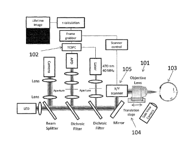
FIG. 1 is a schematic diagram of an optical device in accordance with an
embodiment of the invention. Fluorescence excitation is achieved by a pulsed
laser
beam that is focused by a high numerical aperture objective lens 101 into the
eye.
Fluorescence is detected using a time correlation single photon counting
(TCSPC)
technique through a confocal configuration with a fast avalanche photodiode
detector (APD) 102. TCSPC is performed by using a short pulse of light to
excite
the sample (eye) 103 repetitively, and recording the subsequent fluorescence
emission as a function of time. This usually occurs on the nanosecond
timescale.
In the embodiment of FIG. 1, identification of the anatomical structures of
the lens is performed by scanning the objective lens 101 on axis using a
translation
stage 104. The signal is measured at every point along the scan in order to
reveal
the anatomical structures of the anterior segments such as the cornea, lens
capsule
and supranucleus region of the lens. In addition, the scan provides
information
about the pharmaco-kinetics of exogenous amyloid-binding compounds applied to
the eye. Such information provides not only spatial and temporal information
of the
amyloid-binding compound, but also the concentration of the amyloid-binding
compound that penetrates through the cornea and into the aqueous humor.
In the embodiment of FIG. 1, once the location of interest in the eye is
known from the excited natural fluorescence measured at every point along the
axial
scan, another scan is executed in a plane (xy) perpendicular to the optical
axis using
a set of galvanometer mirrors 105. To ensure allocation of the measured
fluorescence decay curves to the corresponding site of the two-dimensional
CA 02807683 2013-02-06
WO 2012/024188 PCT/US2011/047628
- 22 -
scanning, the galvanometer set scanning is synchronized with the laser pulses
and
photodetection for time-correlated individual photon counting. Such an xy-scan
reveals an image with fluorescence decay time information for each site
(pixel). In
the embodiment of FIG. 1, one or more modules may be implemented using
dedicated, specialized hardware modules and/or using a general purpose
computer
specially-programmed to perform the modules' functionality, including, for
example, the Frame Grabber module, TCSPC module, r Calculation module and
scanner control module. A general purpose computer and/or one or more
specialized hardware modules may receive data from each other via data cables
and
data ports appropriate for the modules' functionality.
In the embodiment of FIG. 1, for time-correlated individual photon counting,
the decay curve of the autoiluorescence is registered for each scanned
location of the
lens and thus a two-dimensional representation of the fluorophores'
distributions can
be evaluated and analyzed based on their fluorescence decay time as well as on
their
intensity. The image of the calculated decay times can be encoded by false
colors
and can be superimposed on the intensity image for better clinical
interpretation.
Since the fluorescence decay time is a characteristic for each fluorescence
molecule,
one can determine and separate the fluorophores (amyloid-binding compound from
natural fluorescence of the lens) being excited in the sample volume. By
combining
fluorescence intensity and lifetime measurements, an extra dimension of
information
is obtained to discriminate among several fluorescent labels.
As discussed herein, a device in accordance with an embodiment of the
invention may comprise a light source. As used herein a "light source" may be
any
light source that can be configured to emit light to illuminate the eye with
at least
one of a wavelength and a polarization of light appropriate to produce
fluorescence
in at least an amyloid-binding compound when the amyloid-binding compound is
bound to the amyloid protein, in a fashion such that the time decay rate of
fluorescence may subsequently be determined based on the fluorescence that is
received as a result of the illumination.
In an embodiment according to the invention, the light source may be
configured to emit light of an appropriate wavelength for a peak region of a
CA 02807683 2013-02-06
WO 2012/024188 PCT/US2011/047628
- 23 -
fluorescent excitation spectrum for the amyloid-binding compound bound to the
amyloid protein in the eye, and the optical unit may be configured to detect
light of
an appropriate wavelength for a peak region of a fluorescent emission spectrum
for
the amyloid-binding compound bound to the amyloid protein in the eye. For
example, where the amyloid-binding compound is Compound 1/11, the excitation
spectrum has a peak of about 470 nm, and the light source may be configured to
emit light within plus or minus about 20 urn of the peak of about 470 urn,
such as
within plus or minus 5 nm, plus or minus 10 urn, plus or minus 15 nm or plus
or
minus 20 nm of 470 nm. Further, the emission spectrum for Compound #11 has a
peak of about 580 nm, and the optical unit may be configured to detect light
within
plus or minus about 20 mn of the peak of about 580 mu, such as within plus or
minus 5 nm, plus or minus 10 nrn, plus or minus 15 mn or plus or minus 20 nm
of
580 urn. In general, there is typically a shift between the peak of the
excitation
spectrum and the peak of the emission spectrum of a fluorescent compound. In
accordance with an embodiment of the invention, it is useful to use a compound
in
which the peak of the emission spectrum is significantly shifted relative to
the
excitation spectrum, in order to enable the distinguishing of fluorescence
from the
bound fluorophore from natural autofluoreseence of the eye. For example, an
emission spectrum having a peak greater than about 500 nm is advantageous for
distinguishing from the natural autofluorescence of the eye. Compound #11
proves
useful for such a purpose, having an emission spectrum with a peak of about
580
urn, shifted significantly from the excitation spectrum with a peak of about
470 mn.
FIG. 12 is an emission spectrum of the fluorescent amyloid-binding compound
Compound # 11 when excited at 470nm, in accordance with an embodiment of the
invention. Other excitation and emission spectra that may be used will be
apparent
to those of skill in the art based on the foregoing.
In accordance with an embodiment of the invention, the device may use an
"optical unit," which as used herein means any unit that can be configured to
receive
light including fluorescence produced as a result of the illumination of the
eye and to
determine a time decay rate of fluorescence for at least the fluorescence
produced by
the amyloid-binding compound bound to the amyloid protein, the determining
CA 02807683 2013-02-06
WO 2012/024188 PCT/US2011/047628
- 24 -
permitting distinguishing of the presence of the amyloid-binding compound
bound
to the amyloid protein in the eye based at least on the time decay rate, For
example,
with reference to FIG. 1, the optical unit may include one or more of the
objective
lens 101, translation stage 104, scanner 105, photodetector 102, a camera, an
LED,
the various lenses, apertures, beam splitters, dichroic filters, the time
decay
calculation module, the frame grabber module, the TCSPC module, and the
scanner
control module. Portions of the functionality of the optical unit may be
implemented by a specially-programmed general purpose computer, or by
dedicated
hardware, for example for performing time decay calculations.
In accordance with an embodiment of the invention, the functionality of the
objective lens 101, translation stage 104 and scanner with galvanometer
mirrors 105
may be performed using a variety of different possible devices, instead of or
in
addition to those components. Collectively, the functionality of the
translation
stage, objective lens and scanner with galvanometric mirrors are referred to
herein
as being implemented by an "optical scanning unit," which may refer to any
device
or collection of devices that perform the equivalent function of scanning a
light
beam over desired regions of interest in the eye, including for the purpose of
determining reference points within the eye and for the purpose of analyzing
fluorophores within the eye. Such an optical scanning unit may perform the
functions of inducing translation motion of a lens, or motion of lens along a
multi-
dimensional path of motion; and may perform the functions of scanning the
light
over regions of interest, for example performing a point, planar, volumetric
or other
type of scan of the light beam over regions of interest, for example by
inducing
motion in a mirror or other optical device in the optical path of a light
beam.
In the embodiment of FIG. 1, the use of a confocal arrangement means that a
dilation agent need not be used, as may be required in systems in which light
needs
to enter the eye off-axis, for example, at a 45-degree angle. This is of
convenience
to patients.
FIG. 2A is a graph of natural fluorescence intensity versus displacement,
measured during performance of an algorithm for detecting a lens interface in
a scan
along the illumination path (z-scan) of the eye, and FIG. 2B is a graph of the
first
CA 02807683 2013-02-06
WO 2012/024188 PCT/US2011/047628
- 25 -
derivative of the graph of FIG. 2A, in accordance with an embodiment of the
invention. The rationale for the algorithm is the assumption that the location
where
the natural fluorescence intensity value increase is the greatest per unit
scan distance
is a reasonable indicator of where the lens boundary begins. In particular,
the
algorithm determines the distance from the z-scan start point that corresponds
to the
maximum inflection point in the fluorescence intensity. In one embodiment, the
algorithm proceeds as follows, and may run in real time:
1) Gather data in a two dimensional array where the first (independent
variable) dimension is distance from start point, i.e., scan distance, as
measured via
rotary encoder, and the second dimension (dependent variable) is fluorescence
intensity as measured via photon detector (APD).
2) Convolve the data array with a five point moving average profile to
smooth the intensity values, i.e., remove high frequency noise that interferes
with
differentiation.
3) Convolve the smoothed data array with differential profile to obtain the
first derivative of the intensity array.
4) Search the intensity first derivative array for maximum differential
intensity value. This is the maximum inflection point. Determine the
corresponding scan distance.
As shown in FIGS. 2A and 2B, a location of the lens capsule may be
determined using the above technique. Further, the locations of, and distances
between, anatomical structures such as the cornea, aqueous humor and lens may
also
be determined. An offset may be applied to specify a distance of a measurement
from a specific datum along any axis.
FIGS. 3A and 3B are graphs illustrating determination of fluorescence decay
time in accordance with an embodiment of the invention. Fluorescence decay
time
may be calculated by a single or double fit exponential (FIG. 3A) to a curve
of
intensity (here, in photons/sec), versus time (here, in nanoseconds). It can
be also
obtained by a linear fit to the slope (FIG. 3B). As used herein, a "time decay
rate of
fluorescence" signifies a characteristic time constant of a decay curve of
CA 02807683 2013-02-06
WO 2012/024188 PCT/US2011/047628
- 26 -
fluorescence intensity; for example, an exponential time constant or a slope
fitted to
the fluorescence decay curve.
The above algorithms of FIGS. 2A, 2B and 3A, 3B may, for example, be
implemented using dedicated, specialized hardware modules and/or using a
general
purpose computer specially-programmed to perform the above algorithms. Such
modules may, for example, use or receive data from the TCSPC module, Frame
Grabber module, 'r-calculation module of the embodiment of FIG. 1.
FIG. 4 is a schematic diagram illustrating the use of time-correlation single
photon counting, in accordance with an embodiment of the invention, A pulsed
light source 406 excites the sample 403 repetitively. The sample emission is
observed by a detector unit avalanche photodiode (APD) 402, while the
excitation
flashes are detected by a synchronization module (SYNC) 407. A constant
fraction
discriminator (CFD) 408 responds to only the first photon detected -
independent of
its amplitude - from the detector 402. This first photon from sample emission
is the
stop signal for the Time-to- Amplitude Converter (TAC) 409. The excitation
pulses
trigger the start signals. The Multi- Channel Analyzer (MCA) 410 records
repetitive
start-stop signals of the single-photon events from the TAC 409, to generate a
histogram of photon counts as a function of time channel units. The lifetime
is
calculated from this histogram. The MCA may be implemented using a dedicated,
specialized hardware module and/or using a general purpose computer specially-
programmed to perform such tasks; and may be in data communication with a
specially-programmed general purpose computer.
In one embodiment according to the invention, a system comprising a
fluorescent amyloid-binding compound and a device is intended to aid in the
diagnosis of probable Alzheimer's disease in patients who have symptoms and
signs
consistent with Alzheimer's-type dementia following an adequate clinical
examination. The device employs a eonfocal scanning mechanism combined with a
fluorescence lifetime spectroscopy technique. The device enables
identification of
the anatomical structures of the anterior segments of the eye and
discrimination of
fluorescent fluorophores based on their optical signatures.
- 27 -
FIG, 5 shows the structure of Compound #11, which may he used as a
fluorescent amyloid-binding compound in accordance with an embodiment of the
invention. Compound #11 is a fluorescent compound designed according to the
molecular rotor motif, and has been shown to bind to the aggregated beta-
atnyloid
(An) peptide. This, combined with native fluorescence, suggests that Compound
411 is a good candidate for an in vivo marker for A13 aggregates which have
been
found in the lens tissue of Alzheimer's patients. The chemical name for
Compound
411 is RE)-2-(2-(2-methoxyethoxy)ethoxy)ethyl-2-cyano-3-(6-(piperidin-1 -
yl)naphthalen-2-yl)acrylate]. Further information regarding Compound #11 may
be
found in J. Sutharsan et al., "Rational Design of Arnyloid Binding Agents
Based on
the Molecular Rotor Motif," ChemMedChem 2010, 5, 56-60.
Compound 411 has been
formulated into an ophthalmic ointment (Compound 411 Ophthalmic Ointment)
containing approximately 5 mg/g of Compound #11, 80% petrolatum and 20%
mineral oil.
In accordance with an embodiment of the invention, a fluorophorc amyloid-
binding compound may be applied to an eye of an individual to be tested in any
of a.
variety of different possible forms. for example, the fluorophore amyloid-
binding
compound may be applied as an ointment, a solution, using a contact lens, by
injection, in liquid form, in solid form, by iontophoresis, or by other
techniques.
A device in accordance with an embodiment of the invention is designed to
detect fluorescence in the time domain with high sensitivity and speed in a
confocal
detection scheme. The device has two main funetionalitics: 11 delivery and
scanning of the optical beam to locations in the anterior segments of the eye,
such as
the supranucleus of the lens, using a translation stage and a galvanometer
scanner;
and 2) identification and discrimination of fluorescent fluorophores based on
fluorescence lifetime measurements.
A device in accordance with an embodiment of the invention identifies
ocular anatomical structures using an axial scan or z-scan, which is based on
the
laser excitation of natural fluorescence of ocular tissues along the optic
axis of the
eye to obtain information on intraocular distances. The z-scan reveals a plot
of
CA 2807683 2019-04-01
CA 02807683 2013-02-06
WO 2012/024188 PCT/US2011/047628
- 28 -
natural fluorescence intensity as a function of depth that provides
infannation about
the location where lifetime measurements are to be performed. The targeted
location may, for example, be the supranucleus of the lens in the human eye.
The
scanning may be completed in seconds, for example in 2 seconds or less, such
as in
about 0.2 seconds, 0.3 seconds, 0.4 seconds, 0.5 seconds, 0.6 seconds, 0.7
seconds,
0.8 seconds, 0.9 seconds, 1.0 seconds, 1.2. seconds, 1.4 seconds, 1.6 seconds,
1.8
seconds or 2.0 seconds to reduce eye motion artifacts, or another amount of
time
appropriate to reduce eye motion artifacts. Alternatively or in addition, the
device
may be used in conjunction with eye-motion tracking to reduce motion
artifacts.
Piezo drives, linear motors and other controlled motion devices may be used
for
such a purpose. The axial scan may also allow measurement of the gradient
concentration of amyloid-binding compound at ocular interfaces such as tear
film/corneal epithelial interface, as well as amyloid-binding compound
bioavailability in the aqueous humor.
A device in accordance with an embodiment of the invention identifies
fluorescent molecules by performing an xy-scan, in which the sample is raster-
scanned with a galvanometer-driven device. The fluorescence lifetime is
registered
for each location scanned of the human lens and thus a two-dimensional
representation of the fluorophore distribution can be evaluated and analyzed
based
on fluorescence decay rate as well as intensity. A two-dimensional
representation of
fluorophore distribution based on decay lifetime, which may also, but need not
necessarily, include a two-dimensional representation based on fluorescence
intensity, is referred to herein as a "fluorescence lifetime image."
In accordance with an embodiment of the invention, fluorescence lifetime
measurements are based on repetitively exciting the eye with short laser
pulses and
recording the subsequent fluorescence emission as a function of time. Since
the
fluorescence decay time is a characteristic of each fluorescence molecule, one
can
determine and separate the amyloid-binding compound from natural fluorescence
of
the lens that is being excited in the sample volume.
In particular, in an embodiment according to the invention, fluorescence
lifetime measurements may be obtained by a time correlation single photon
counting
CA 02807683 2013-02-06
WO 2012/024188 PCT/US2011/047628
- 29 -
technique (TCSPC). The scanning speed and data acquisition may be synchronized
and executed, for example, in 0.5 seconds to reduce any eye motion artifacts,
or
another amount of time appropriate to reduce eye motion artifacts. The TCSPC
principle is based on the detection of single photons emitted by a pulsed
laser and
recording of the detection times of the arriving individual photons. When a
photon
is detected, the time of the corresponding detector pulse is measured. The
events are
collected in memory for many detected photons. Fluorescence decay lifetimes
can
be calculated by constructing a histogram from the individual time
measurements.
A device in accordance with an embodiment of the invention, operating in TCSPC
mode, can achieve, for example, count rates of about 107 photons per second.
Therefore, 104 photons can be collected in less than 1 ms. Such count rates
are
important where high speed is necessary to acquire fast scanning information
in the
lens of the human eye. Other count rates may be used.
A device in accordance with an embodiment of the invention may be
designed to obtain specific information from a particular location in the lens
of the
human eye. Examples of such locations include the supranucleus, lens capsule,
nucleus, cornea and aqueous humor.
This is achieved by precise alignment of the subject, knowledge of the ocular
anatomy of the eye, and obtaining information of fluorophores in a scanned
area in
the lens with high specificity and sensitivity. A schematic diagram of an
optical
platform in accordance with an embodiment of the invention is shown in FIG. 1
(discussed also above). Fluorescence excitation is achieved by a pulsed laser
beam
that is focused by a high numerical aperture objective lens 101 into the eye
103.
The laser may, for example, be pulsed at a repetition rate of about 40MHz and
produce pulses of about 200 picoseconds wide, although other repetition rate
and
pulse widths may be used. For example, repetition rates from as low as about 1
MHz up to about 240 MHz may be used, and pulse widths of from about 40
picoseconds to about 400 picoseconds may be used. The optical beam then is
reflected off a pair of galvanometer scanners and is focused by a high
numerical
objective lens 101 which is mounted on a translation stage 104. The
fluorescence
measurements in the supranucleus of the eye are obtained by first aligning the
CA 02807683 2013-02-06
WO 2012/024188 PCT/US2011/047628
- 30 -
subject eye to the device and performing 1) a z-scan to determine the location
of the
region of interest (ROT) and 2) an xy-scan to obtain specific information over
an
area within the supranueleus.
In accordance with an embodiment of the invention, subject alignment
consists of identifying the focal plane of the objective lens as a reference
starting
point of the measurement. A light emitting diode (LED), which is used also as
a
fixation target, is focused by the objective lens 101 onto the cornea of the
eye 103 in
the shape of a ring. A camera is used to visualize the reflection of the ring
off the
surface of the cornea. Once this is achieved, the scanning of the eye can be
performed to obtain the necessary information.
In accordance with an embodiment of the invention, identification of the
anatomical structures of the lens is performed by scanning the objective lens
101
along the optical axis (on axis) using a translation stage 104. The z-scan
involves
the excitation of the natural fluorescence with the laser source and
identification of
the anatomical structures of the anterior segments such as the cornea, lens
capsule
and supranuelens region of the lens and their relative distances. In addition,
the scan
can provide information about the pharmacokinetics of exogenous amyloid-
binding
compound applied to the eye.
In accordance with an embodiment of the invention, once the region of
interest is identified in the eye using the z-scan measurement, a planar scan
(xy-
scan) in the plane perpendicular to the axial scan is performed using the
galvanometer mirrors. To ensure allocation of the measured fluorescence decay
curves to the corresponding site of the two-dimensional scanning, the
galvanometer
mirrors are synchronized with the data acquisition board for TCSPC
measurements.
An xy-scan may entail, for example, scanning a region 50 by 50 [tm in the
supranucleus of a human eye in 0.5 seconds and extracting lifetime decay
values. It
will be appreciated that regions of other sizes and locations, and times of
scans, may
be used.
In accordance with an embodiment of the invention, detection is achieved
with TCSPC through a confocal configuration with a fast avalanche photodiode
detector (APD) 102. Fluorescence from the excited molecules is collected with
the
CA 02807683 2013-02-06
WO 2012/024188 PCT/US2011/047628
-31 -
same objective lens 101 as the excitation laser, filtered after the dichroic
mirror with
an additional band-pass filter to reject remaining scattered laser light and
passed
through a small aperture to enable confocal detection. With fast-timing
option, the
APD 102 may, for example, provide timing resolution better than 50 picoseconds
Full Width Half Maximum with photon detection efficiency of 49% at 550 nm,
although other timing resolutions and photon detection efficiencies may be
used.
An illustration of the data acquisition and electronics behind TCSPC is
shown in FIG. 4 (discussed also above), in accordance with an embodiment of
the
invention. The pulsed light source 406 excites the sample 403 repetitively at
(for
example) a 40MHz repetition rate while the excitation pulses are detected by a
synchronization (SYNC) module 407 which is set (for example) also at 40MHz.
The excitation pulses trigger the start signals. A constant fraction
discriminator
(CFD) 408 responds to only the first photon detected from the detector,
independent
of its amplitude. This first photon from sample emission is the stop signal
for the
Time-to-Amplitude Converter (TAC) 409. When the APD 402 detects a photon, a
short pulse is created at the output of the PMT. The pulse is "cleaned" by the
CFD
408 and enters the TAC 409 as a "stop" pulse. Once the stop pulse (i.e.; the
first
arriving photon) has been detected, the voltage ramp is stopped and the
voltage
value (equivalent to the time difference between the start and stop pulses) is
transmitted to the Multi-Channel Analyzer (MCA) 410. The MCA 410 records
repetitive start-stop signals of the single-photon events from the TAC 409 and
increments the counts in the channel in correspondence with the detected
voltage
(time). This process is repeated with each pulse and eventually, after many
cycles, a
histogram of photon counts as a function of time channel units is generated.
The
histogram represents the fluorescence intensity as a function of time, from
which the
fluorescence decay lifetime is obtained.
In accordance with an embodiment of the invention, the data acquisition may
be performed using the Picaflarp 300 TCSPC (PicoQuant, GmbH, Berlin,
Germany) PC-board working in the special Time-Tagged Time-Resolved Mode,
which stores all relevant information for every detected photon for further
data
analysis. In particular, every photon arrival time is recorded at the detector
in
CA 02807683 2013-02-06
WO 2012/024188 PCT/US2011/047628
- 32 -
synchronization with the laser excitation pulse and the position of the sample
and
the number of the detection channel. The sync rate of the acquisition board
may, for
example, be set at 40 MHz with a time resolution of 4 picoseconds and channel
count depth of 16 bit (other sync rates, time resolutions and channel count
depths
may be used).
In accordance with an embodiment of the invention, the software acquisition,
which may be performed using SymPhoTime, (PicoQuant, GmbH, Berlin,
Germany), may be controlled via a TCP/IP network and synchronized with both
the
galvanometer scanner and the acquisition board through TTL signals to define
the
line and the frame of the image. SymPhoTime in LSM command mode may, for
example, record and display the fluorescence lifetime and intensity images.
In accordance with an embodiment of the invention, the fluorescence
lifetime may be registered for each location scanned within the human lens,
and thus
a two-dimensional representation of the fluorophore distribution can be
evaluated
and analyzed based on fluorescence decay rate and intensity. A constructed
color
coded image based on fluorescence lifetime decay can be superimposed on the
intensity image to facilitate clinical interpretation. The calculation of a
fluorescence
lifetime image may be done by sorting all photons which correspond to one
pixel
into a histogram, which is then fitted to an exponential decay function to
extract the
lifetime information. This procedure is then repeated for every pixel in the
image.
The software algorithm may fit the data to multi-exponential decay functions
using
tail-fitting as well as numerical re-convolution. As the fitting procedure
relies on the
quality of the start parameters for the fit, frequency count of photons of
specific
decay rates that is indicative of specific fluorophores over an area scan can
be
extracted directly from the image. The foregoing algorithms may be implemented
by computer, and may involve displaying data on a two-dimensional display such
as
a computer monitor.
In one embodiment according to the invention, an average intensity
associated with a specific lifetime decay may be used as a measure of
aggregation of
amyloid proteins. That is, a parameter can be created by averaging a
fluorescent
intensity, associated with a specific lifetime decay, over a specific area.
This
CA 02807683 2013-02-06
WO 2012/024188 PCT/US2011/047628
-33 -
parameter can be used as a measure of aggregation, for example to monitor
progression of a disease in an individual based on changes in the parameter.
Such a
parameter may be determined by computer or other specialized hardware.
A fluorescent histogram of the fluorescent amyloid-binding compound
Compound #11 is shown in FIG. 6, obtained by a device in accordance with an
embodiment of the invention. Single exponential fitting results in a lifetime
decay
rate of 2 nsec.
FIG. 7 shows a fluorescence lifetime image of Compound #11 and its
corresponding intensity image, obtained in accordance with an embodiment of
the
invention. The images are 100 X 100 pixels obtained in 0.5 seconds and
represent a
scanning area of 50 X 50 microns.
An embodiment according to the invention uses a fluorescence time domain
technique to detect and resolve fluorophores based on their lifetime
signature. By
combining fluorescence intensity and lifetime measurements, an extra dimension
of
information is obtained to discriminate among fluorescent labels. In vitro
studies
discussed in Experiment #1 demonstrate the capability of an embodiment
according
to the invention in differentiating fluorescent fluorophores based on their
lifetime
decay signature. Further, the pharmacokinetics studies on rabbit eyes
discussed in
Experiment #2 show detectable fluorescence signal of the fluorescent amyloid-
binding compound Compound #11 in the supranucleus of the lens. More important,
the signal detected in the lens of the rabbit eye was easily identified and
assigned to
the amyloid-binding compound itself.
It will be understood by a person skilled in the art that any method presented
herein (as well as individual steps thereof and combinations of several
subsequent
steps of these methods), in particular the technical steps involving the
collection and
optionally processing of relevant data, the comparison of the data thus
obtained with
the normal control values and/or the finding of any significant deviation
during that
comparison, may be performed ahead of, independent thereof and in preparation
of a
subsequent, separate diagnosis step, i.e., prior to attributing a potential
deviation
between the values obtained and the normal control value(s) to a particular
amyloidogenic disorder such as Alzheimer's disease (the actual diagnosis).
These
CA 02807683 2013-02-06
WO 2012/024188 PCT/US2011/047628
- 34 -
methods (including individual steps as well as combinations of several
subsequent
steps of these methods) performed ahead of, independent thereof and in
preparation
of a subsequent, separate diagnosis are specifically contemplated as
individual
embodiments of the invention.
In accordance with an embodiment of the invention, various sub-components
of the system may be supplied by existing suppliers. For example, excitation
sources may be the Picosecond Pulsed Laser, LDH series, sold by PicoQuant of
Berlin, Germany; the Picosecond Diode Laser, BDL series, sold by Becker &
Hickl
= of Berlin, Germany; or the Picosecond Light Pulser, PLP series, sold by
Hamamatsu
Photonics of Hamamatsu, Japan. Data acquisition may be performed using the
TCSPC module, PicoHarp 300, sold by PicoQuant, Berlin, Germany; the TCSPC
module, SPC series, sold by Becker & Hickl, Berlin, Germany; or the
Synchronous
Delay Generator, C10647 sold by Hamamatsu Photonics, Hamamatsu, Japan.
Photon Counting Detectors may be the Detector Unit, PMA series, sold by
PicoQuant, Berlin, Germany; the Detector Unit, ID-100 Series, sold by Becker &
Hickl, Berlin, Gemiany; or the Streakscope (C10627 series, sold by Hamamatsu
Photonics, Hamamatsu, Japan). It will be appreciated that other excitation
sources,
data acquisition modules and photon counting detectors may be used.
Portions of the above-described embodiments of the present invention can be
implemented using one or more computer systems. For example, the embodiments
may be implemented using hardware, software or a combination thereof. When
implemented in software, the software code can be executed on any suitable
processor or collection of processors, whether provided in a single computer
or
distributed among multiple computers.
Further, it should be appreciated that a computer may be embodied in any of
a number of forms, such as a rack-mounted computer, a desktop computer, a
laptop
computer, a tablet computer, a single circuit board computer or a system on a
chip.
Additionally, a computer may be embedded in a device not generally regarded as
a
computer but with suitable processing capabilities, including a Personal
Digital
Assistant (PDA), a smart phone or any other suitable portable or fixed
electronic
device.
CA 02807683 2013-02-06
WO 2012/024188 PCT/US2011/047628
- 35 -
Also, a computer may have one or more input and output devices. These
devices can be used, among other things, to present a user interface. Examples
of
output devices that can be used to provide a user interface include printers
or display
screens for visual presentation of output and speakers or other sound
generating
devices for audible presentation of output. Examples of input devices that can
be
used for a user interface include keyboards, and pointing devices, such as
mice,
touch pads, touch screens and digitizing tablets. As another example, a
computer
may receive input information through speech recognition or in other audible
format.
Such computers may be interconnected by one or more networks in any
suitable foil'', including as a local area network or a wide area network,
such as an
enterprise network or the Internet. Such networks may be based on any suitable
technology and may operate according to any suitable protocol and may include
wireless networks, wired networks or fiber optic networks.
Also, the various methods or processes outlined herein may be coded as
software that is executable on one or more processors that employ any one of a
variety of operating systems or platfoims. Additionally, such software may be
written using any of a number of suitable programming languages and/or
programming or scripting tools, and also may be compiled as executable machine
language code or inteimediate code that is executed on a framework or virtual
machine.
In this respect, at least a portion of the invention may be embodied as a
computer readable medium (or multiple computer readable media) (e.g., a
computer
memory, one or more floppy discs, compact discs, optical discs, magnetic
tapes,
flash memories, circuit configurations in Field Programmable Gate Arrays or
other
semiconductor devices, or other tangible computer storage medium) encoded with
one or more programs that, when executed on one or more computers or other
processors, perform methods that implement at least a portion of the various
embodiments of the invention discussed above. The computer readable medium or
media can be transportable, such that the program or programs stored thereon
can be
CA 02807683 2013-02-06
WO 2012/024188 PCT/US2011/047628
- 36 -
loaded onto one or more different computers or other processors to implement
various aspects of the present invention as discussed above.
In this respect, it should be appreciated that one implementation of at least
a
portion of the above-described embodiments comprises at least one computer-
readable medium encoded with a computer program (e.g., a plurality of
instructions), which, when executed on a processor, performs some or all of
the
above-discussed functions of these embodiments. As used herein, the term
"computer-readable medium" encompasses only a computer-readable medium that
can be considered to be a machine or a manufacture (i.e., article of
manufacture). A
computer-readable medium may be, for example, a tangible medium on which
computer-readable information may be encoded or stored, a storage medium on
which computer-readable information may be encoded or stored, and/or a non-
transitory medium on which computer-readable infolination may be encoded or
stored. Other non-exhaustive examples of computer-readable media include a
computer memory (e.g., a ROM, a RAM, a flash memory, or other type of computer
memory), a magnetic disc or tape, an optical disc, and/or other types of
computer-
readable media that can be considered to be a machine or a manufacture.
The terms "program" or "software" are used herein in a generic sense to refer
to any type of computer code or set of computer-executable instructions that
can be
employed to program a computer or other processor to implement various aspects
of
the present invention as discussed above. Additionally, it should be
appreciated that
according to one aspect of this embodiment, one or more computer programs that
when executed perform methods of the present invention need not reside on a
single
computer or processor, but may be distributed in a modular fashion amongst a
number of different computers or processors to implement various aspects of
the
present invention.
Computer-executable instructions may be in many forms, such as program
modules, executed by one or more computers or other devices. Generally,
program
modules include routines, programs, objects, components, data structures, etc.
that
perform particular tasks or implement particular abstract data types.
Typically the
CA 02807683 2013-02-06
WO 2012/024188 PCT/US2011/047628
- 37 -
functionality of the program modules may be combined or distributed as desired
in
various embodiments.
Experiment #1 ¨ In vitro Study of Neuroptix Fluorescent Ligand with
beta amyloid peptide (1-42):
In accordance with an embodiment of the invention, in vitro studies on
aggregated AP peptides bound to Compound #11 were performed. Fluorescence
lifetime measurements of Compound #11 with aggregated A(3 peptide were
performed using a device in accordance with an embodiment of the invention.
FIG.
8A is a fluorescence lifetime image showing Compound #11 and Compound #11
bound to aggregated Ap peptide, with their corresponding fluorescence lifetime
histograms shown in FIG. 8B, in accordance with an embodiment of the
invention.
By fitting the lifetime histograms, the decay rates are determined. The
results
demonstrate the superior performance of an embodiment in accordance with the
invention that is capable of differentiating between fluorophores of lifetime
difference of as little as 0.85 nsec with low level of photon detection. An
experimental description follows.
The purpose of this in vitro study was to identify the optical signature of
the
Compound #11 amyloid-binding compound, and to characterize its fluorescence
properties when bound to aggregated Aj3 peptide. In particular, the objectives
of the
study were: 1) characterization of Compound #11 lifetime decay rates; and 2)
ability
to detect and differentiate between Compound #11 bound and un-bound to beta
amyloid (AP) peptides.
Device:
The Neuroptix SAPPHIRE II device (Neuroptix Corporation, Acton, MA,
U.S.A.) is a purpose built device for clinical studies in humans, which was
adapted
for in vitro measurements for this experiment. It employs a confoeal scanning
mechanism combined with fluorescence lifetime spectroscopy that allows
differentiation of fluorophores. The device allows 1) scanning of the optical
beam
to specific locations in the anterior segments of the eye, such as the
supranucleus
CA 02807683 2013-02-06
WO 2012/024188 PCT/US2011/047628
- 38 -
and 2) identification of fluorescent fluorophores based on fluorescence
lifetime
measurements.
Method ¨ Aggregated AP peptides preparation:
Aggregated Af3 peptide was prepared by dissolving AP(1-42) in PBS pH 7.4
to a final concentration of 100 M. This solution was magnetically stirred at
1200
rpm for 3 days at room temperature. The 100 M AP(1-42) stock solution in PBS
was aliquoted and frozen at -80 C for up to 4 weeks without noticeable change
in
its property. 150 L, of pre-aggregated AP(1-42) was added to 2.85 mL of
Compound #11 to attain a final concentration of 5 M A13(1-42) and 4 i_tM of
Compound #11. The solution was transferred to 5 mL vial and the fluorescence
measurements were performed at 25 C.
Experiment and Results-
The sample consisting of Compound #11 was placed in front of the
Neuroptix SAPPHIRE II Device. Once the location of the scan in the sample was
determined, a raster scan was performed to obtain fluorescence lifetime
measurements. FIG. 8A shows an image (200 X 200 pixels) with a scan range of
100 lam X 100 na obtained in 1 second acquisition time. The image is shaded
to
represent lifetime decays. The shading that makes up most of the image
background
represents a lifetime decay of 1.4 nsec, which corresponds to that of the
fluorescence
amyloid-binding compound. The spot detected in the image is that of the
aggregated
AP peptide representing a lifetime decay of 2.25 nsec. The plot in FIG. 8B
shows
the fluorescence decay rates calculated for both the Compound #11 and that of
the
Compound #11 bound to aggregated Af3 peptide.
Conclusion
In vitro fluorescence lifetime measurements of Compound #11 with
aggregated AP peptide were performed with Neuroptix SAPPHIRE II Device.
Based on fluorescence lifetime decay rates, bound and unbound peptide to
Compound #11 can be resolved. The results demonstrate the superior performance
of the SAPPHIRE II Device that is capable of differentiating between
fluorophores
with 0.85nsec difference in lifetime just by detection level of a few hundred
photons.
CA 02807683 2013-02-06
WO 2012/024188 PCT/US2011/047628
- 39 -
Experiment #2 - Ocular Pharmacokinetics Study in Dutch-Belted
Rabbits:
In accordance with an embodiment of the invention, in vivo
pharmacokineties studies of Compound #11 in rabbit eyes were performed using a
device in accordance with an embodiment of the invention. FIG. 9A is a plot of
the
frequency count of photons of specific decay rates measured on two rabbits
dosed
with the amyloid-binding compound along with a controlled rabbit. The
frequency
count of photons of specific decay rates that pertained to the fluorescent
amyloid-
binding compound (Compound#11) was calculated from the fluorescence histogram
(FIG. 9B), in accordance with an embodiment of the invention. The results
demonstrate the capability of the amyloid-binding compound to penetrate the
cornea
and be detected by the device in the lens of rabbit eyes. An experimental
description
follows.
Introduction
Ocular pharmacokinctic investigation of dose response via topical
administration of fluorescence amyloid-binding compound was performed in Dutch-
belted rabbits. The rabbits were tested each day over a 4 day period using
Compound #11 amyloid-binding compound in an ointment. Two animals were
dosed in the right eye with Compound 411 (0.5%) in ointment foal'. Onc animal
was untreated and used as control animal. The animals were dosed at specific
time
points for four days and tested with SAPPIIIRE II system for fluorescence
intensity
and lifetime measurements at the beginning and end of each day.
The results demonstrate:
1) Detectable fluorescence signal was achieved with concentration of 5mg/g
Compound 411 in ointment Balm after repetitive topical administration.
2) The fluorescence measurements performed at the beginning and at the end
of the day and over a period of four days show increase of Compound #11
fluorescence in the lens nucleus of the rabbit eyes.
Methods:
CA 02807683 2013-02-06
WO 2012/024188 PCT/US2011/047628
- 40 -
Ocular measurements were performed at the time intervals and dose
concentrations stated in the table below.
Group Treatment # of Animals Dosage by Ocular
Toxikon
Measurements
by Sponsor
1 5 mg/g 2 Ointment SAPPHIRE II
(Ointment) dosed for 4 tests at the
days at 830, beginning and
1130 and 1430 end of each day
Control 1 SAPPHIRE IT
tests at the
beginning and
end of each day
Table 1: Animal Group tested, dosages administered, and measurement times
The study was staggered over four days and performed in a single location
and on asingle instrument. Tests were performed in a dimly lit room dedicated
to
the study.
All animals were dosed with Compound #11 via topical ocular application
and tested in the right eye. Animals were anesthetized and manually held on a
platform in front of the Neuroptix SAPPHIRE II device. Gross positioning was
done by the animal handler, and fine tuning of the measurement location was
done
by the Neuroptix SAPPHIRE II operator. Once aligned, the SAPPHIRE II operator
initiated the measurement sequence. Baseline measurements were made on the
animals before dosing, and then at the beginning and end of each day (Table
1).
Experimental Design and Dosage:
Fluorescence lifetime and intensity measurements were performed in the eye
at the beginning and at the end of each day. The measurements entailed
scanning
the rabbit eye axially (z-scan) to obtain inter-ocular information and a
planar scan
CA 02807683 2013-02-06
WO 2012/024188 PCT/US2011/047628
-41 -
(xy-scan) to perform lifetime decay measurements in a certain region of the
eye,
which is the lens nucleus in this case.
Once the location of interest was identified, Time Correlation Single Photon
Counting (TCSPS) was initiated while performing the xy-scan. The fluorescence
lifetime images were then obtained where the decay lifetime histogram was
obtained
for each pixel location. The calculated decay times were color coded in the
fluorescence lifetime image. Each measurement was performed three times. The
frequency count of photons of specific decay rates were calculated from the
decay
rates frequency that of the Compound #11 signature obtained in the xy-scan and
averaged over the three measurements. Calibration measurements were taken once
a
day on a fluorescence dye and showed repeatable performance with no apparent
drift
throughout the study. The device was specifically designed for human use but
the
platform was slightly modified for holding the rabbits.
Dosing was performed by Toxikon staff via topical ocular application into
the right eye of each animal.
Group 1: Animals were anesthetized with subcutaneous injection of
Dexdomitor (0.5mg/kg), Ketamine (5mg/kg). A ribbon of ointment approximately
1/2 inch long was then applied to the lower right eyelid of each animal in the
test
group three times a day for four days.
Control: For the control group, one animal was handled in the same way as
the animals in the test groups except no ointment or solution was administered
to the
eye.
Summary of Results:
Fluorescence intensity and lifetime measurements of the amyloid-binding
compound in the eye were perfottned at the beginning (morning) and end
(evening)
of each day. FIGS. 10A and 10B are plots showing the frequency count of
photons
of specific decay rates that pertain to Compound 1111 measured in the morning
for
baseline and at the end of the day after being dosed during the four day study
period
in the lens nucleus of the five rabbits. FIG. 10A is a plot for the morning
measurements, and FIG. 10B is a plot for the evening measurements, both being
on
rabbits dosed with Compound #11 Ophthalmic Ointment. The measurements on the
- 42 -
two rabbits (1002 and 1003), which were dosed with Compound #1 I Ophthalmic
Ointment, show significant increase in fluorescence signal in the nucleus of
the eye.
FIGS. 10A and 1013 show that after three dosages each day with three hours
separation, a cumulative fluorescence signal is measured along the 4 day study
period.
in FIGS, HA and 11B arc two fluorescence lifetime images taken at baseline
and after the end of the fourth day of the study with animal 1003. The
baseline
measurement exhibited a black image indicative of no presence of Compound #11
in
the lens of the eye. After four days, an xy-scan revealed a lifetime image
with a
decay rate of 2 nsec (displayed in gray) which is a signature of the
fluorescence
lifetime. The difference in signal collected between the two rabbits can be
attributed
to the dosing variation by the technician and blinking by the animal.
Conclusion
The primary objective was achieved with Compound #I1 Ophthalmic
Ointment at a concentration of 5 mg/g. Repetitive topical administration of
Compound #11 tended to accumulate in the nucleus after several hours of
application and tended to stay there for at least 12 hours.
While this invention has been particularly shown and described with
references to example embodiments thereof, it will be understood by those
skilled in
the art that various changes in form and details may be made therein without
departing from the scope of the invention encompassed by the appended claims.
CA 2807683 2019-04-01