Note: Descriptions are shown in the official language in which they were submitted.
CA 02816689 2014-12-03
FOLDABLE TENT
BACKGROUND OF THE INVENTION
[0002] The present invention relates to a tent and more particularly to a
foldable or
collapsible tent.
[0003] For novice campers and camping families, among others, foldable tents
are a popular
alternative to conventional assemble-to-use tents. These tents are commonly
referred to as
"instant tents," "one-touch tents" or "pop-up tents." Foldable tents are
typically sold with a
frame assembly and tent fabric permanently attached to each other, i.e.,
preassembled.
Erecting and collapsing the tent is easy and less time consuming than
conventional assemble-
to-use tents because the frame assembly and tent fabric are collectively
opened and folded.
The frame assembly usually includes a single central hub and a plurality of
poles pivotally
attached to the hub to provide a stable tent structure. These types of instant
tents are
particularly advantageous because a minimal number of poles, typically four,
are required and
thus erecting and collapsing the instant tent is quite simple. Although
convenient for the user,
there are several disadvantages for instant tents in the prior art.
[0004] For example, a large amount of stress is exerted on the frame assembly
due to the
tension from the tent fabric. These stresses are often transferred to and
concentrated on the
single central hub where the poles are interconnected, especially when a wind
force is exerted
on the tent. Thus, there is risk of damage or even failure of the central hub.
[0005] Also, the size of instant tents in the prior art today are limited and
could typically
accommodate only up to nine people because stability of the structure is
compromised with
1
CA 02816689 2014-12-03
longer poles required for larger instant tents. Therefore, even though there
is great interest for
bigger tents (often including separate rooms), this cannot be achieved with an
instant tent
today. Instead, larger tents that could accommodate more than nine people are
of the
conventional type which requires the user to separately assemble the poles and
then attach the
poles to the tent fabric for set up, and detach the poles from tent fabric and
disassemble the
poles to store and transport.
[0006] Another disadvantage of instant tents of the prior art is that head
room is limited. The
central portion of the instant tent where the central hub is located serves as
the apex of the
tent. Even though cabin instant tents attempt to solve this problem, the poles
are positioned
downwardly and the ceiling height decreases from the central portion of the
tent. Thus, head
room is still limited at radially outer portions of the tent.
[0007] As another example, instant tents in the prior art are limited in
shape. They are either
dome shape or a single rectangular cabin. The use of a single central hub also
limits the
overall configuration of the instant tent because the overall length of the
tent is restricted by
the length of the poles which can securely extend from the central hub.
Therefore, a tent with
a more elongated configuration or other configurations cannot be achieved.
100081 Instant tents today also pose problems with folding the tent into a
relatively short and
compact state. The folded length of the tent as well as the volume of the tent
is dictated by
the sections of the poles which are connected to the central hub and because
those pole
sections are usually elongated to increase the overall volume of the tent in
the open
configuration, the instant tent is relatively long when folded.
2
CA 02816689 2014-12-03
OBJECTS AND SUMMARY OF THE INVENTION
100091 The following presents a simplified summary of some embodiments of the
invention
in order to provide a basic understanding of the invention. This summary is
not an extensive
overview of the invention. It is not intended to identify key/critical
elements of the invention
or to delineate the scope of the invention. Its sole purpose is to present
some embodiments of
the invention in a simplified form as a prelude to the more detailed
description that is
presented later.
[0010] The present invention is intended to overcome at least the above-
described
disadvantages. The objects and advantages of the present invention, more
specifically, are to
provide: an instant tent where the stresses exerted on the frame are more
evenly distributed so
that the risk of damage or failure to the frame assembly is reduced; a safe
instant tent with
larger volume so that more people could be accommodated; an instant tent with
increased
head room throughout the tent; an instant tent having configurations other
than dome or
traditional cabin configurations; and an instant tent capable of folding into
a more compact
state.
[0010a] Certain exemplary embodiments can provide a foldable tent comprising a
frame
assembly coupled to a tent fabric, the frame assembly and tent fabric
collectively collapsible
from an open configuration to a folded configuration, the frame assembly
comprising: a first
hub spaced apart from a second hub, each hub having an upwardly facing top
portion when in
the open configuration; a central roof pole having opposing ends, the central
roof pole
positioned at a central portion of the frame assembly, each respective end of
the roof pole
pivotally coupled with the first and second hubs; and a plurality of leg poles
each having an
inner end and an outer end, each leg pole being collapsible in between the
inner and outer
_3
CA 02816689 2014-12-03
ends, the inner ends of each leg pole pivotally coupled to a corresponding
hub, wherein in the
open configuration each leg pole extends radially outward with respect to the
central roof pole
and the outer ends of each leg pole engages a ground surface; wherein the tent
fabric is fixable
and slidably coupled to the frame assembly such that the tent fabric is
positioned within a
radially inner space surrounded by the frame assembly when the tent is in the
open
configuration; and wherein in the folded configuration the central roof pole
and leg poles are
pivoted upward with respect to each hub to a position substantially
perpendicular to each hub
such that top portions of each hub face each other and the central roof pole
and leg poles are
positioned substantially between the hubs.
[0010b] Certain exemplary embodiments can provide a foldable tent comprising a
frame
coupled to a canopy, the frame and canopy collectively collapsible from an
open
configuration to a folded configuration, the frame comprising: a central hub
positioned at an
apex of the tent when in the open configuration, a plurality of roof poles
having an inner end
and an outer end, each roof pole inner end pivotally coupled to the central
hub and extending
radially outward therefrom, a plurality of auxiliary hubs, each roof pole
outer end pivotally
coupled to a corresponding auxiliary hub, and a plurality of collapsible leg
poles each having
an inner end and an outer end, the inner ends of each leg pole pivotally
coupled to a respective
auxiliary hub, the outer ends of each leg pole engaging a ground surface when
the tent is in
the open configuration; wherein the canopy is permanently slidably coupled to
the frame such
that the canopy is positioned within a radially inner space surrounded by the
frame when the
tent is in the open configuration; wherein at least three poles are coupled to
each auxiliary
hub; wherein in the folded configuration each of the poles connected to the
central hub are
pivoted downward with respect to the central hub and each of the poles
connected to a
4
CA 02816689 2014-12-03
respective auxiliary hub are pivoted upward with respect to each auxiliary hub
such that each
auxiliary hub is adjacent to each other and the poles are disposed
substantially between the
auxiliary hubs and the central hub.
10010cl Certain exemplary embodiments can provide a foldable tent comprising a
frame
coupled to a canopy, the frame and canopy collectively collapsible from an
open
configuration to a folded configuration, the frame comprising: a plurality of
hubs, each hub
spaced apart and positioned at an upper portion of the frame, at least one
upper roof pole
having opposing ends, the opposing ends of each of the at least one upper roof
poles being
pivotally coupled with two adjacent hubs, the opposing ends of the at least
one upper roof
pole being substantially aligned when in the folded configuration, a plurality
of lower roof
poles having first and second ends, the first ends of each lower roof pole
pivotally coupled to
a corresponding hub, each lower roof pole extending radially outward from each
respective
hub and away from the upper roof pole, the lower roof poles folded upwardly
from each
respective hub to the folded configuration, and a plurality of side poles
having first and
second ends, the first ends of each side pole pivotally coupled to a
corresponding lower roof
pole second end forming an angle between said poles when in the open
configuration, the
second ends of each side pole engagable with a ground surface, each side pole
being
collapsible at a portion between the first and second ends of the side pole;
wherein the canopy
is slidably coupled to the frame such that the canopy is positioned within a
radially inner
space surrounded by the frame when the tent is in the open configuration; and
wherein in the
folded configuration each of poles are folded with respect to each respective
hub and
positioned substantially between the hubs.
CA 02816689 2014-12-03
[0011] Other embodiments provide a foldable tent comprising a frame coupled to
a canopy
where the frame and canopy are collectively collapsible from an open
configuration to a
folded configuration. The frame comprises a plurality of hubs, each hub spaced
apart and
positioned at an upper portion of the frame, at least one upper roof pole
having opposing
ends, the opposing ends of each of the at least one upper roof poles being
pivotally coupled
with two adjacent hubs, a plurality of lower roof poles having first and
second ends, the first
ends of each lower roof pole pivotally coupled to a corresponding hub, each
lower roof pole
extending radially outward from each respective hub and away from the upper
roof pole, and
a plurality of side poles having first and second ends, the first ends of each
side pole pivotally
coupled to a corresponding lower roof pole second end forming an angle between
said poles
when in the open configuration, the second ends of each side pole engagable
with a ground
surface, each side pole being collapsible at a portion between the first and
second ends of the
side pole. A canopy is fixedly slidably coupled to the frame such that the
canopy is
positioned within a radially inner space surrounded by the frame when the tent
is in the open
configuration.
[0012] Other embodiments provide a foldable tent comprising a frame assembly
coupled to a
tent fabric, the frame assembly and tent fabric collectively collapsible from
an open
configuration to a folded configuration. The frame assembly comprises a first
hub spaced
apart from a second hub; a central roof pole having opposing ends, the central
roof pole
positioned at a central portion of the frame assembly, each respective end of
the roof pole
pivotally coupled with the first and second hubs; and a plurality of leg poles
each having an
inner end and an outer end, each leg pole being collapsible in between the
inner and outer
ends, the inner ends of each leg pole pivotally coupled to a corresponding
hub, wherein in the
6
CA 02816689 2014-12-03
open configuration each leg pole extends radially outward with respect to the
central roof pole
and the outer ends of each leg pole engages a ground surface; wherein the tent
fabric is
fixedly slidably coupled to the frame assembly such that the tent fabric is
positioned within a
radially inner space surrounded by the frame assembly when the tent is in the
open
configuration.
[0013] Other embodiments provide a foldable tent comprising a frame coupled to
a canopy,
the frame and canopy collectively collapsible from an open configuration to a
folded
configuration. The frame comprises a central hub, a plurality of roof poles
having an inner
end and an outer end, each roof pole inner end pivotally coupled to the
central hub and
extending radially outward therefrom, a plurality of auxiliary hubs, each roof
pole outer end
pivotally coupled to a corresponding auxiliary hub, and a plurality of
collapsible leg poles
each having an inner end and an outer end, the inner ends of each leg pole
pivotally coupled
to each hub, the outer ends of each leg pole engaging a ground surface when
the tent is in the
open configuration; wherein the canopy is permanently slidably coupled to the
frame such
that the canopy is positioned within a radially inner space surrounded by the
frame when the
tent is in the open configuration.
BRIEF DESCRIPTION OF THE DRAWINGS
[0014] To better understand the present invention, a more particular
description of the
invention will be rendered by reference to the appended drawings.
[0015] Fig. 1 is a perspective view of an embodiment of a foldable tent of the
present
invention in an open configuration;
[0016] Fig. 2 is a perspective view of another embodiment of a foldable tent
of the present
invention in an open configuration;
7
CA 02816689 2014-12-03
[0017] Fig. 3 is a perspective view of another embodiment of a foldable tent
of the present
invention in an open configuration;
[0018] Fig. 4 is a front perspective view of an embodiment of a frame assembly
of the present
invention, shown in Figs. 1-3, in an open configuration;
[0019] Fig. 5 is a front perspective view of the frame assembly of Fig. 4 in a
first partially
folded configuration;
[0020] Fig. 6 is a front perspective view of the frame assembly of Fig. 4 in a
second partially
folded configuration;
[0021] Fig. 7 is a front perspective view of the frame assembly of Fig. 4 in a
fully folded
configuration;
[0022] Fig. 8 is perspective view of another embodiment of a foldable tent of
the present
invention;
[0023] Fig. 9 is a perspective view of an embodiment of a frame assembly of
the present
invention, shown in Fig. 8 without retractable roof poles, in an open
configuration;
[0024] Fig. 10 is a perspective view of the frame assembly of Fig. 9 in a
partially folded
configuration;
[0025] Fig. 11 is a perspective view of the frame assembly of Fig. 9 in a
fully folded
configuration;
[0026] Fig. 12 is a perspective view of another embodiment of a frame assembly
of the
present invention in an open configuration;
[0027] Fig. 13 is a perspective view of the frame assembly of Fig. 12 in a
partially folded
configuration;
8
CA 02816689 2014-12-03
[0028] Fig. 14 is a perspective view of the frame assembly of Fig. 12 in a
fully folded
configuration;
[0029] Fig. 15 is a perspective view of another embodiment of a frame assembly
of the
present invention in an open configuration with a lower portion of the leg
poles retracted;
[0030] Fig. 16 is a perspective view of the frame assembly of Fig. 15 in a
partially folded
configuration;
[0031] Fig. 17 is a perspective view of the frame assembly of Fig. 15 in a
fully folded
configuration;
[0032] Fig. 18 is a schematic plan view of an embodiment of a foldable tent of
the present
invention with the frame assembly of Fig. 15;
[0033] Fig. 19 is a perspective view of another embodiment of a frame assembly
of the
present invention in an open configuration with a lower portion of the leg
poles retracted;
[0034] Fig. 20 is a perspective view of the frame assembly of Fig. 19 in a
partially folded
configuration;
[0035] Fig. 21 is a perspective view of the frame assembly of Fig. 19 in a
fully folded
configuration;
[0036] Fig. 22 is a schematic plan view of an embodiment of a foldable tent of
the present
invention with the frame assembly of Fig. 19;
[0037] Fig. 23 is a perspective view of another embodiment of a frame assembly
of the
present invention in an open configuration with a lower portion of the leg
poles retracted;
[0038] Fig. 24 is a perspective view of the frame assembly of Fig. 23 in a
partially folded
configuration;
9
CA 02816689 2014-12-03
[0039] Fig. 25 is a perspective view of the frame assembly of Fig. 23 in a
fully folded
configuration;
[0040] Fig. 26 is a schematic plan view of another embodiment of a foldable
tent of the
present invention with the frame assembly of Fig. 23;
[0041] Fig. 27 is a perspective view of another embodiment of a foldable tent
of the present
invention;
[0042] Fig. 28 is a perspective view of another embodiment of a frame assembly
of the
present invention, shown in Fig. 27, in an open configuration;
[0043] Fig. 29 is a perspective view of the frame assembly of Fig. 28 in a
partially folded
configuration;
[0044] Fig. 30 is a perspective view of the frame assembly of Fig. 28 in a
fully folded
configuration;
[0045] Fig. 31 is a perspective view of another embodiment of a foldable tent
of the present
invention;
[0046] Fig. 32 is a perspective view of another embodiment of a frame assembly
of the
present invention, shown in Fig. 31, in an open configuration;
[0047] Fig. 33 is a perspective view of the frame assembly of Fig. 32 in a
partially folded
configuration;
[0048] Fig. 34 is a perspective view of the frame assembly of Fig. 32 in a
fully folded
configuration;
[0049] Fig. 35 is a perspective view of an embodiment of an instant tent hub
of the present
invention;
[0050] Fig. 36 is a plan view of the instant tent hub of Fig. 35;
CA 02816689 2014-12-03
[0051] Fig. 37 is a side view of the instant tent hub of Fig. 35;
[0052] Fig. 38 is a partial perspective view of another embodiment of an
instant tent hub of
the present invention in an open configuration; and
[0053] Fig. 39 is a partial perspective view of the instant tent hub of Fig.
38 in a folded
configuration.
[0054] To facilitate an understanding of the invention, identical reference
numerals have been
used, when appropriate, to designate the same or similar elements that are
common to the
figures. Further, unless stated otherwise, the features shown in the figures
are not drawn to
scale, but are shown for illustrative purposes only.
DETAILED DESCRIPTION OF THE INVENTION
[0055] Certain terminology is used in the following description for
convenience only and is
not limiting. The article "a" is intended to include one or more items. Where
only one item is
intended, the term "one" or similar language is used. Additionally, to assist
in the description
of the present invention, words such as top, bottom, front, rear, right and
left are used to
describe the accompanying figures. The terminology includes the words above
specifically
mentioned, derivatives thereof, and words of similar import.
[0056] Referring to Figs. 1-3, three separate embodiments 101-103 of a
foldable tent of the
present invention are shown. Each of these embodiments include a frame
assembly 110 as
illustratively shown in Figs. 4-7, which is foldable from an open
configuration as shown in
Fig. 4 to a folded configuration as shown in Fig. 7.
[0057] Referring to Figs. 4-7, the frame assembly 110 generally includes a
pair of spaced
apart hubs 111 which are configured to receive poles for pivotal engagement.
In this
embodiment, as shown in Figs. 35-37, each hub 111 includes three slots 112 for
pivotally
11
CA 02816689 2014-12-03
attaching each pole but additional slots could be included depending on the
desired overall
configuration of the tent. Each pole is attached to a corresponding slot 112
by a fastener such
as a screw or pin which extends through opposing apertures (or partial
apertures) 114 of each
slot 112. In the closed configuration each pole is pivotable upwardly to a
position
substantially perpendicular to a top surface of the hub as illustrated in the
drawings of the
folded configuration of the frame assemblies, and in the open configuration
each pole is
pivotable downwardly to a position where the poles extend radially outwardly
from the hub
111 as illustrated in the drawings of the open configuration of the frame
assemblies. The
angle at which each pole extends in the open configuration depends on the
configuration of a
top surface 116 of each slot and the position of the apertures 114. For
example, a lower top
surface 116 coupled with the apertures 114 positioned at a higher level would
yield a
horizontal or a more upwardly extending pole. Thus, the positions of the top
surface 116 and
apertures 114 could be adjusted to form a desired extending angle for each
pole. Other instant
tent hubs capable of having poles pivotable upward to the folded
configuration, such as those
described in U.S. Patent Application Nos. 12/658,473 (filed February 4, 2010),
13/295,396
(filed November 14, 2011) and 13/560,021 (filed July 27, 2012), could be used
herein without
departing from the scope of the present invention.
[0058] As shown in Fig. 4, one of the slots of each hub 112 faces the other
such that a central
roof pole 121 is pivotally attached to the opposing hubs 111. When in the open
configuration,
the central roof pole 121 is substantially horizontal to create more head room
compared with
conventional single hub foldable tents. In this embodiment, the central roof
pole 121 is one
continuous piece but it could also be constructed of multiple sections and
telescopically
connected if a more elongated tent configuration is desired.
12
CA 02816689 2014-12-03
[0059] Still referring to Figs. 4-7, the frame assembly 110 also includes a
plurality of leg
poles 131. Each leg pole 131 includes an inner end 133 and an outer end 135.
In this
embodiment, two leg poles 131 support each side of the frame assembly 110. The
inner ends
133 are pivotally connected to each hub 111 as described above and the leg
poles 131 are
extended radially outward and away from the central roof pole 121. As
mentioned above,
additional leg poles could be attached to each hub 111 depending on the
desired configuration
of the tent. Each leg pole 131 includes an upper section (or lower roof pole)
137, a middle
section 139 and a lower section 141. In this embodiment, the upper and middle
sections 137,
139 are pivotally coupled together with a conventional pivoting joint 143
which includes
opposing upwardly facing channels (not shown) positioned above a bottom
surface (not
shown) for receiving each of the adjoining sections 137, 139. The pivoting
joint 143 is
configured such that when the frame assembly 110 is in the open configuration
as shown in
Fig. 4, the upper and middle sections 137, 139 are fixed at an angle, and such
that the upper
and middle sections 137, 139 could be folded against each other when the frame
assembly is
in the partially folded and fully folded configurations as shown in Figs. 6
and 7, respectively.
In this embodiment, the diametrical dimensions of the middle and lower
sections 139, 141 are
such that the sections 139, 141 are telescopically coupled together and
lockable in an
extended position by conventional means, for example, with a locking mechanism
145 having
a spring biased pin extending through aligned apertures of each section 139,
141. However,
one of ordinary skill in the art will recognize that other methods and means
could be used to
couple and lock the middle and lower sections 139, 141 including but not
limited to a lockable
pole joint such that the sections 139, 141 are lockably extended, and unlocked
and pivotably
13
CA 02816689 2014-12-03
folded toward each other. Referring to Fig. 4, when the frame assembly 110 is
in an open
configuration, the frame assembly 110 surrounds a radially inner space 147.
[0060] In the present embodiment, each pole 121, 137, 139 and 141 is
constructed of a rigid
tubular steel having a diameter between 14.5mm and 16mm. However, in another
embodiment, as shown in Fig. 2, the roof pole 121, upper poles 137 and middle
poles 139 are
constructed of a flexible fiberglass reinforced plastic (FRP), and the lower
poles 141 are
constructed of tubular steel such that each middle pole 139 is telescopically
retractable within
a corresponding lower pole 141. One of ordinary skill in the art will
recognize that other
materials such as other metals (e.g., aluminum), metal alloys, other polymers,
composite
materials or any combination thereof could be used, and different sizes of
poles could be used
depending on desired strength without departing from the scope of the
invention.
[0061] Referring to Figs. 1-3, several embodiments of a foldable tent of the
present invention
are shown for which the frame assembly 110 shown in Figs. 4-7 is utilized.
Each of the
embodiments include a tent fabric or canopy 151 which is disposed within the
radially inner
space 147 formed by the frame assembly 110. In one embodiment 101, shown in
Fig. 1, the
tent fabric 151 has a roof, four side walls and a floor stitched together to
form an enclosure
153. The foldable tent 101 is shown with features such as doors, windows and
vents,
however, the tent could be constructed with more or less features than shown.
Also, each of
the pivoting joints 143 are covered with a fabric casing 157 which protects
the tent fabric 151
from damage when the tent is folded. The hubs 111 could be covered with fabric
casings as
well. The enclosure 153 is attached by slidable hooks 155 at various locations
to the frame
assembly 110. In the open configuration as shown in Fig. 1, the enclosure 153
is substantially
taut and forms a substantially flat surfaces on the roof, side walls and
floor. The frame
14
CA 02816689 2014-12-03
assembly 110 is further stabilized by the tension created by the tent fabric
151. In this
embodiment, the rigid frame assembly 110 coupled with the tent fabric 151
forms a cabin
style tent.
[0062] Referring to Fig. 2, in another embodiment of a foldable tent of the
present invention
102, the roof pole 121, upper poles 137 and middle poles 139 are flexible FRP
and the lower
poles 141 are tubular steel. The tent fabric 151 includes an inner tent or
enclosure 153 and an
integral rain fly which are slidably attached to the frame assembly 110 in the
same manner as
described above with respect to the cabin tent 101. In this embodiment, a top
portion of the
tent fabric includes sleeves 159 which attach to the frame assembly 110 but
the sleeves could
be replaced with hooks or other conventional attachment means such as hook-and-
loop, hook-
and-eye or the like. In addition, the hubs 111 are provided with a fabric
casing 157 which
protects the tent fabric 151 from damage during the folding process. In the
open
configuration as shown in Fig. 2, the tent fabric 151 is substantially taut
and tension is applied
to the frame assembly 110 which provides additional stability to the tent 102.
A curvature is
formed on the roof pole 121 as well as the leg poles 131 due to the
utilization of flexible FRP
and a dome style tent is provided.
100631 Referring to Fig. 3, another embodiment of a foldable tent of the
present invention 103
is shown. In this embodiment, the tent fabric 151 includes only a roof portion
and portions
along the leg poles 131 to form an open shelter. Similar to the tents 101, 102
described
above, in the open configuration as shown in Fig. 3, the tent fabric 151 is
substantially taut
and exerts a radially inward tension to the frame assembly 110 to provide
additional stability.
One of ordinary skill in the art will recognize that other tent fabrics could
be attached. For
CA 02816689 2014-12-03
example, a tent fabric partially constructed of mesh having a roof and side
walls without a
floor could be utilized to form a screen house.
[0064] Referring to Figs. 4-7, even though the tent fabric 151 is attached to
the frame
assembly 110 at all times, the operation of the embodiments of the foldable
tent 101-103
shown in Figs. 1-3 is shown without the tent fabric 151 for purposes of
clarity. From the
open configuration (Fig. 4), the middle and lower sections of the leg poles
139, 141 are
retracted to form a first folded section (Fig. 5). Each of the first folded
sections are pivoted
outwardly about each corresponding pivoting joint 143 toward each
corresponding upper
section 137 to form a second folded section (Fig. 6). Each second folded
section is then
pivoted about each hub 111 such that the poles 121, 131 are pivoted upward
with respect to
each hub 111 into a fully folded configuration (Fig. 7). In the fully folded
configuration, top
portions of each hub 111 face each other and are in substantial parallel
relationship. The tent
101-103 is unfolded to the open configuration in reverse order of the steps
described above.
[0065] The structure of these embodiments of instant tents of the present
invention 101-103
provides stability and could be constructed as an instant tent of all sizes
that could
accommodate anywhere from two people to more than nine.
[0066] Referring to Figs. 8-25, several embodiments of another frame assembly
for a foldable
tent of the present invention are shown. In these embodiments, each frame
assembly 202,
204, 206, 208, 210 includes a central hub 211 interconnected with auxiliary
hubs 213 by roof
poles 221 to provide support for oversized instant tents.
[0067] In one embodiment of a foldable tent 201, shown in Figs. 8-11, the
frame assembly
202 includes a central hub 211 positioned at a central portion of the tent
201. In this
embodiment, the central hub 211 is the tent hub shown and described in U.S.
Patent No.
16
CA 02816689 2014-12-03
7,861,736. Referring to Figs. 38-39, an embodiment of the central hub 211 is
shown. In
general, the central hub 211 includes a biasing mechanism (not shown) which is
placed into
the inside of a shaft 21 of a base 2, and a sliding plate 4 positioned
radially into cut-outs 23 of
the base 2 and secured to a hub 1 with securing bolts 7 via vertical holes
(not shown) of the
base 2 and vertical holes 13 of the hub 1, so that the biasing mechanism is
located in between
the sliding plate 4 and a top inner surface of the shaft 21. The shaft 21 is
movably fit into a
central channel 12 of the hub 1. The roof poles 221 are pivoted respectively
on pole slots 11
of the hub 1. Pivoting bases 51 are fixedly attached to the roof poles 221.
Braces 6 are
pivoted respectively on brace slots 22 of the base 2 on one end, and the other
ends of the
braces 6 are individually pivoted on corresponding pivoting bases 51 at lower
engagement
point 51A. In the open configuration as shown in Fig. 38 the roof poles 221
extend radially
outward from the central hub 211. The central hub 211 could be configured such
that the
poles extending therefrom could extend to a substantially horizontal position.
In the folded
configuration as shown in Fig. 39 the roof poles 221 are pivoted downward to a
substantially
vertical position. The forces exerted on the roof poles 221 from the biasing
member allow the
frame assembly 202 to maintain its open and folded configurations without a
locking
mechanism. Figs. 38 and 39 are shown with four slots 11, however, the hub 211
could be
modified to include more or less slots depending on the number of poles
pivotally attached
thereto. One of ordinary skill in the art will recognize that other hubs could
be used so long
as the poles connected thereto are pivotable downward to a folded
configuration.
[0068] Auxiliary hubs 213 are positioned on opposing sides of the central hub
211 such that
each of the hubs are aligned along a common vertical plane. The auxiliary hubs
213 of this
embodiment are substantially similar to the hub 111 shown in Figs. 35-37 and
described
17
CA 02816689 2014-12-03
above. Each auxiliary hub 213 is connected to the central hub 211 with a roof
pole 221 to
form a roof portion of the tent 201. Each roof pole 221 is pivotally connected
to each
opposing hub 211, 213 at upper engagement point 5A. As it will be described in
other
embodiments below, the frame assembly 210 could be constructed with more than
two roof
poles depending on the desired overall configuration of the tent. Also, the
roof poles 221
could have multiple collapsible sections to add length to the tent 202 when in
the open
configuration while maintaining a relatively short pole length when collapsed
or retracted in
the folded configuration. For example, as shown in Fig. 9, each roof pole 221
includes two
sections which are telescopically retractable by conventional spring pin-
aperture means as
described above. One of ordinary skill in the art will recognize that other
means could be
utilized, for example, a lockable joint for folding each section or other
sliding means, without
departing from the scope of the present invention.
100691 Still referring to Figs. 8-11, the frame assembly 202 also includes a
plurality of leg
poles 231. Each leg pole 231 includes an inner end 233 and an outer end 235.
In this
embodiment, the leg poles 231 support the central portion as well as each side
portion of the
frame assembly 202. The inner ends 233 are pivotally connected to each hub
211, 213 and
the leg poles 231 are extended radially outward and away from the central
portion of the
frame assembly 202. In this embodiment, four leg poles 231 are pivotally
connected with the
central hub 211. However, as shown in another embodiment in Fig. 12, two leg
poles 231
could be connected to the central hub 211. Moreover, additional leg poles 231
could be
attached to each hub 211, 213 depending on the desired overall appearance of
the tent without
departing from the scope of the present invention. Each leg pole 231 includes
an upper
section (or lower roof pole) 237, a middle section 239 and a lower section
241. In this
18
CA 02816689 2014-12-03
embodiment, the upper and middle sections 237, 239 are pivotally coupled
together with a
conventional pivoting joint 243 which includes opposing channels (not shown)
positioned
above a bottom surface (not shown) for receiving each of the adjoining
sections 237, 239.
The pivoting joint 243 is configured such that when the frame assembly 202 is
in the open
configuration as shown in Fig. 9, the upper and middle sections 237, 239 are
fixed at an angle,
and such that the upper and middle sections 237, 239 could be folded against
each other when
the frame assembly 202 is in the partially folded and fully folded
configurations as shown in
Figs. 10 and 11, respectively. In this embodiment, the middle and lower
sections 239, 241 are
telescopically coupled together by conventional means and lockable in an
extended position
with a spring biased locking mechanism 245. However, one of ordinary skill in
the art will
recognize that other methods and means could be used to couple and lock the
middle and
lower sections 239, 241 including but not limited to a lockable pole joint
such that the
sections 239, 241 are pivotable toward each other when folding the frame
assembly 202.
Referring to Fig. 9, in an open configuration, the frame assembly 202
surrounds a radially
inner space 247.
[0070] Referring to Fig. 8, a foldable tent 201 of the present invention is
shown for which the
frame assembly 202 (without retractable roof poles) shown in Figs. 9-11 is
utilized. A tent
fabric or canopy 251 is disposed within the radially inner space 247 formed by
the frame
assembly 202. In this embodiment, the tent fabric 251 is an enclosure 253
having a roof, four
side walls and a floor stitched together. The foldable tent 201 is shown with
features such as
doors, windows and vents, however, the tent could be constructed with more or
less features
than shown. Also, each of the pivoting joints 243 and auxiliary hubs 213 are
covered with a
fabric casing 257 which protects the tent fabric 251 from damage when the tent
is folded. The
19
CA 02816689 2014-12-03
enclosure 253 is fixedly slidably attached by slidable hooks 255 at various
locations to the
frame assembly 202. In the open configuration as shown in Fig. 8, the
enclosure 253 is
substantially taut and forms a substantially flat surface on the roof, side
walls and floor. The
frame assembly 202 is further stabilized by the tension created by the tent
fabric 251. In this
embodiment, the rigid frame assembly 202 coupled with the tent fabric 251
forms a cabin
style tent. One of ordinary skill in the art will recognize that other tent
fabrics could be
attached to the frame assembly 202. For example, a tent fabric having a roof,
side walls
partially constructed of mesh and no floor could be utilized to form a screen
house, or a tent
fabric having only a roof and additional fabric along the leg poles could be
utilized to form an
open shelter.
100711 Referring to Figs. 9-11, even though the tent fabric 251 is attached to
the frame
assembly 202 at all times and collectively opened and folded, the operation of
the foldable
tent shown in Fig. 8 is shown without the tent fabric 251 for purposes of
clarity. From the
open configuration (Fig. 9), the middle and lower sections of the leg poles
239, 241 are
retracted to form a first folded section. Each of the first folded sections
are pivoted outward
and upward about each corresponding pivoting joint 243 toward each
corresponding upper
section 237 to form a second folded section (Fig. 10). Each of the roof poles
221 are also
retracted and pivoted downward with respect to the central hub 211. Each
second folded
section is then pivoted upward about each auxiliary hub 213 into a fully
folded configuration
(Fig. 11). In the fully folded configuration, top portions of each auxiliary
hub 213 and a
bottom portion of the bottom portion of the central hub 211 face each other.
10072] Referring to Figs. 12-14, another embodiment of a frame assembly 204 of
the present
invention is shown. The structural components of this embodiment are
substantially identical
CA 02816689 2014-12-03
to the frame assembly 202 described above for which identical components are
referenced
with identical numbers, and the folding method is identical to the frame
assembly 202
described above. In this embodiment, only two leg poles 231 extend from the
central hub 211
and the roof poles 221 are not retractable. This type of frame assembly is
more compact with
fewer components and could be used for smaller instant tents, shelters and
screen houses.
10073] Referring to Figs. 15-18, another embodiment of a frame assembly 206 of
the present
invention is shown. The structural components of this embodiment are
substantially identical
to the frame assembly 202 described above for which identical components are
referenced
with identical numbers, and the folding method is identical to the frame
assembly 202
described above. In this embodiment, four leg poles 231 extend from the
central hub 211,
while two retractable roof poles 221 extend from the central hub 211
substantially at a right
angle. Referring to Fig. 18, when the tent fabric 251 is attached to the frame
assembly 206
(by the same means and method described above with respect to the tent 201), a
substantially
L-shaped cabin tent 205 is formed. This overall configuration allows for a
larger tent which
could be provided with interior dividers (not shown) to form separate rooms
and/or vestibules
(not shown) and multiple entrances.
100741 Referring to Figs. 19-22, another embodiment of a frame assembly 208 of
the present
invention is shown. The structural components of this embodiment are
substantially identical
to the frame assembly 202 described above for which identical components are
referenced
with identical numbers, and the folding method is identical to the frame
assembly 202
described above. In this embodiment, four leg poles 231 extend from the
central hub 211,
while three retractable roof poles 221 extend from the central hub 211. Two of
the roof poles
221 are substantially aligned with each other while the remaining roof pole
221 extends
21
CA 02816689 2014-12-03
substantially perpendicular to the other two roof poles 221. Referring to Fig.
22, when the
tent fabric 251 is attached to the frame assembly 208 (by the same means and
method
described above with respect to the tent 201), a substantially T-shaped cabin
tent 207 is
formed. This overall configuration allows for a larger tent which could be
provided with
interior dividers (not shown) to form separate rooms and/or vestibules (not
shown) and
multiple entrances.
100751 Referring to Figs. 23-26, another embodiment of a frame assembly 210 of
the present
invention is shown. The structural components of this embodiment are
substantially identical
to the frame assembly 202 described above for which identical components are
referenced
with identical numbers, and the folding method is identical to the frame
assembly 202
described above. In this embodiment, four leg poles 231 extend from the
central hub 211,
while four retractable roof poles 221 extend from the central hub 211. Two of
the roof poles
221 are substantially aligned with each other while the other two roof poles
221 are
substantially aligned with each other and extend substantially perpendicular
to the other two
roof poles 221. Referring to Fig. 26, when the tent fabric 251 is attached to
the frame
assembly 210 (by the same means and method described above with respect to the
tent 201), a
substantially X-shaped cabin tent 209 is formed. This overall configuration
allows for a
larger tent which could be provided with interior dividers (not shown) to form
separate rooms
and/or vestibules (not shown) and multiple entrances.
[0076] In the present embodiments 201-210, each pole 221, 237, 239 and 241 is
constructed
of a rigid tubular steel having a diameter between 14.5mm and 16mm. One of
ordinary skill
in the art will recognize that other materials such as other metals (e.g.,
aluminum), metal
alloys, other polymers and composite materials or any combination thereof
could be used, and
22
CA 02816689 2014-12-03
different sizes of poles could be used depending on desired strength without
departing from
the scope of the invention.
[0077] The various embodiments shown in Figs. 8-25 provide a larger foldable
tent which the
market today lacks. Specifically, foldable or instant tents necessary for
accommodating more
than nine people are non-existent because foldable tent frame assemblies of
the prior art
cannot support such volume. Instead, foldable tents with such large volume
often times fail or
collapse during moderate to heavy winds. Therefore, larger tents in the prior
art must be
manually assembled and disassembled. The frame assemblies shown in the Figs. 8-
25,
however, are easy to set up and fold, and provide the much needed larger
instant tent with
increased head space. Furthermore, the various embodiments of the frame
assemblies 202,
204, 206, 208, 210 could be used with a variety of tent fabrics pre-assembled
to the frame
assembly to form, for example, an enclosed instant tent, an open instant
shelter or an instant
screen house.
[0078] Referring to Figs. 27-34, other embodiments of a foldable tent of the
present invention
are shown. Specifically, Figs. 27-30 show an embodiment having a hexagonal
structure 301
and Figs. 31-34 show an embodiment having an octagonal structure 303.
100791 Referring to Figs. 27-30, the foldable tent 301 includes a central hub
311 having three
radially spaced apart roof poles 321, inner ends of which are pivotally
connected to the central
hub 311 for pivotal movement from a substantially horizontal position in an
open
configuration to a downward vertical position in a folded configuration. In
this embodiment,
the central hub 311 is identical to the central hub 211 described with respect
to the frame
assembly 202 above. In an open configuration, as shown in Figs. 27 and 28, the
roof poles
321 extend radially outward from the central hub 311 and are pivotally
connected to
23
CA 02816689 2014-12-03
corresponding auxiliary hubs 313 at outer ends. The auxiliary hubs 313 of this
embodiment
are substantially similar to the hub 111 shown in Figs. 35-37 and described
above, and are
configured for pivotally connecting with poles such that the poles are
pivotable upwardly
from the open configuration to a closed configuration as shown in Figs. 29 and
30. The roof
poles 321 could have multiple collapsible or retractable sections if desired.
[0080] Still referring to Figs. 27-30, the frame assembly 302 also includes a
plurality of leg
poles 331. Each leg pole 331 includes an inner end 333 and an outer end 335.
In this
embodiment, the leg poles 331 support the roof portion as well as radially
outer portions of
the frame assembly 302. The inner ends 333 are pivotally connected to each
auxiliary hub
313 and the leg poles 331 are extended radially outward and away from the
central portion of
the frame assembly 302. In this embodiment, two leg poles 331 are pivotally
connected with
each auxiliary hub 313. However, additional leg poles could be attached to
each auxiliary hub
313 depending on the desired overall appearance of the tent. Each leg pole 331
includes an
upper section (or lower roof pole) 337, a middle section 339 and a lower
section 341. In this
embodiment, the upper and middle sections 337, 339 are pivotally coupled
together with a
conventional pivoting joint 343 which includes opposing channels (not shown)
positioned
above a bottom surface (not shown) for receiving each of the adjoining
sections 337, 339.
The pivoting joint 343 is configured such that when the frame assembly 302 is
in the open
configuration as shown in Figs. 27 and 28, the upper and middle sections 337,
339 are fixed at
an angle, and such that the upper and middle sections 337, 339 could be folded
against each
other when the frame assembly 302 is in the partially folded and fully folded
configurations as
shown in Figs. 29 and 30, respectively. In this embodiment, the middle and
lower sections
339, 341 are telescopically coupled together by conventional means and
lockable in an
24
CA 02816689 2014-12-03
extended position with a spring biased locking mechanism 345. However, one of
ordinary
skill in the art will recognize that other methods and means could be used to
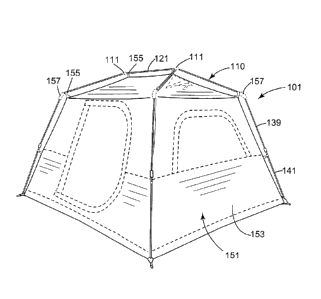
couple and lock
the middle and lower sections 339, 341 including but not limited to a lockable
pole joint such
that the sections 339, 341 are pivotable toward each other when folding the
frame assembly.
Referring to Fig. 28, when the frame assembly 302 is in an open configuration,
the frame
assembly 302 surrounds a radially inner space 347.
[0081] Referring to Fig. 27, a tent fabric or canopy 351 is disposed within
the radially inner
space 347 formed by the frame assembly 302. In this embodiment, the tent
fabric 351 is a
partial enclosure 353 having an impermeable roof and six permeable side walls
(preferably
mesh) stitched together while having an open floor to form a screen house.
Screen houses are
particularly useful when one desires ample ventilation and/or shade while
preventing bugs or
mosquitoes from entering living quarters or entertaining space. The foldable
tent or screen
house 301 is shown with features such as doors having slide fasteners
(zippers) and ground
flaps, however, the tent could be constructed with more or less features than
shown. Also,
each of the pivoting joints 343 and auxiliary hubs 313 are covered with a
fabric casing 357
which protects the tent fabric 351 from damage when the tent is folded, but
could be
constructed without the fabric casings 357. The enclosure 353 is permanently
slidably
attached by hooks 355 at various locations to the frame assembly 302. In the
open
configuration as shown in Fig. 27, the partial enclosure 353 is substantially
taut and forms a
substantially flat surface on the roof and side walls. The frame assembly 302
is further
stabilized by the tension created by the tent fabric 351. In this embodiment,
the rigid frame
assembly 302 coupled with the tent fabric 351 forms a hexagonal screen house.
One of
ordinary skill in the art will recognize that other tent fabrics could be
attached to the frame
CA 02816689 2014-12-03
assembly 302. For example, a fully enclosed tent fabric having a roof, side
walls and floor
stitched together could be utilized to form an enclosed tent or a tent fabric
having only a roof
and optional fabric along the leg poles could be utilized to form an open
shelter.
100821 Referring to Figs. 31-34, another embodiment of a foldable tent 303
with another
embodiment of a frame assembly 304 of the present invention is shown. The
structural
components of this embodiment are substantially identical to the frame
assembly 302 and tent
fabric 351 described above with respect to the foldable tent 301, for which
identical
components are referenced with identical numbers. In this embodiment, four
roof poles 321
pivotally extend from the central hub 311 on one end and each roof pole 321 is
pivotally
connected with a corresponding auxiliary hub 313 on an opposing end. Two leg
poles 331 are
pivotally connected to and extend radially outward from each auxiliary hub 313
to form an
octagonal screen house. In each of the embodiments 301, 303, the poles 321,
331 are
constructed of hollow steel having a diameter between 14.5mm and 16mm to
provide
sufficient strength to support the overall structure through windy conditions.
However, other
materials of different sizes could be used such as aluminum, metal alloys,
fiberglass
reinforced plastic, composite materials or any combination thereof.
[0083] Referring to Figs. 28-30 and 32-34, even though the tent fabric 351 is
attached to the
frame assembly 302, 304, respectively, at all times, the operation of the
foldable tent shown in
Figs. 27 and 31 is shown without the tent fabric 351 for purposes of clarity.
From the open
configuration (Figs. 28 and 32), the middle and lower sections of the leg
poles 339, 341 are
retracted to form a first folded section. Each of the first folded sections
are pivoted outward
and upward about each corresponding pivoting joint 343 toward each
corresponding upper
section 337 to form a second folded section (Figs. 29 and 33). Each of the
roof poles 321 are
26
CA 02816689 2014-12-03
also retracted and pivoted downward with respect to the central hub 311. Each
second folded
section is then pivoted upward about each auxiliary hub 311 into a fully
folded configuration
(Fig. 30 and 34). In the fully folded configuration, top portions of each
auxiliary hub 311 face
the central hub 311.
100841 The embodiments shown in Figs. 27-34 and described in detail above
provide a large
but stable tent structure to accommodate a large number of people. Head room
is ample and a
comfortable and safe outdoor environment is provided while ease in set up and
folding is
achieved.
100851 In instant tents of the prior art, the roof portion of the tent is
supported with a single
central hub and several continuous poles which extend to the upper corners of
the tent. In the
present embodiments 101-103, 201-210 and 301-304, the angles (with respect to
a horizontal
plane) at which the central roof pole 121, 221, 321 and lower roof poles 137,
237, 337 extend
are much less than the angle at which a continuous pole of comparable instant
tents of the
prior art extends, and thus, more volume and head room are provided.
100861 Also, the stresses in tent structures are mostly concentrated on the
upper or roof
portion of the frame assembly where the poles are closer to a horizontal
position. For foldable
frames of the prior art which utilize only a single central hub and have
continuous upper poles
extending from the central hub to the upper corners of the tent, those
stresses are concentrated
on the central hub and upper poles. This requires the use of a substantially
large hub and
upper poles with larger diameters to accommodate for those stresses. Even so,
damage to or
failure of the central hub is possible. For the tents of the present invention
101-103, 201-210,
301-304, the upper structure of the tent, i.e., hubs 111, 211, 213, 311, 313;
roof pole 121, 221,
321; and lower roof pole 137, 237, 337; serves as a means for more evenly
distributing the
27
CA 02816689 2014-12-03
stresses generated from the tent fabric 151, 251, 351 and other elements such
as wind.
Because the stresses are more evenly distributed among smaller pole sections
and multiple
hubs, smaller hubs are utilized and poles with a small diameter can be used,
thereby reducing
the overall weight of the tent and also cutting material cost.
[0087] Moreover, in these embodiments 101-103, 201-210, 301-304, the tent is
capable of
being folded into a more compact state than a comparable instant tent of the
prior art.
Especially, for the tent embodiments 201-210, 301, 303, the tent is capable of
being folded
into a compact state despite the large volume of the tent in the open
configuration which can
accommodate a large number of people. This is because the overall folded
length of the tent
is dictated by the length of the roof pole 121, 221, 321 which covers a
partial length of the
roof. In contrast, roof poles used for instant tents with single central hubs
covers the entire
diagonal length of the roof spanning from the center to corner. Almost
invariably, the length
of the roof pole 121, 221, 321 whether retracted or not, is less than the
length of roof poles of
comparable tents in the prior art. Thus, the compact folded instant tents of
the present
invention 101-103, 201-210, 301-304 are advantageous for storage and
transport.
[0088] The present invention may be embodied in other specific forms without
departing
from its essential characteristics. The described embodiments are to be
considered in all
respects only as illustrative and not restrictive. The scope of the invention
is, therefore,
indicated by the appended claims rather than by the foregoing description. All
changes which
come within the meaning and range of equivalency of the claims are to be
embraced within
their scope.
28