Note: Descriptions are shown in the official language in which they were submitted.
LNG DISPENSER INCLUDING MEASURING DEVICES
DESCRIPTION
[001]
Field of the Disclosure
[002] Embodiments of the present disclosure include dispensers, and more
particularly, dispensers for dispensing and metering a liquid, such as
liquefied
natural gas.
Background of the Disclosure
[003] Generally
speaking, liquefied natural gas (LNG) presents a viable fuel
alternative to, for example, gasoline and diesel fuel. More specifically, LNG
may be
utilized as an alternative fuel to power certain vehicles. However, a primary
concern
in commercializing LNG includes accurately measuring the amount of LNG that is
dispensed for use. Particularly, the National Institute of Standards and
Technology
of the United States Department of Commerce has developed guidelines for
federal
Weights and Measures certification, whereby dispensed LNG must be metered on a
mass flow basis with a certain degree of accuracy. Such a mass flow may be
calculated by measuring a volumetric flow rate of the LNG and applying a
density
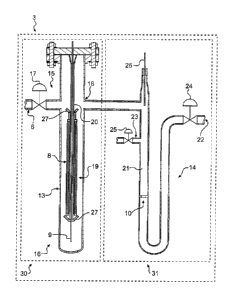
factor of the LNG to that volumetric flow rate.
[004] Typically, LNG dispensers may be employed to dispense LNG for
commercial use. Such LNG dispensers may use mass flow measuring devices,
such as a Corilois-type flow meter, or may include devices to determine the
density
of the LNG and the volumetric flow of the LNG. For example, the density may be
determined by measuring the dielectric constant and the temperature of the LNG
flowing through the dispenser. As the LNG flows through a dispensing chamber
of
the dispenser, a capacitance probe may measure the dielectric constant, and a
temperature probe may measure the temperature. The measured dielectric
constant
and temperature may then by utilized to calculate the density of LNG flowing
through
the dispenser by known principles. A volumetric flow rate of the LNG may then
be
determined by, for example, a volumetric flow meter associated with the
dispensing
- 1 -
CA 2819610 2018-09-07
CA 02819610 2013-05-31
WO 2012/075096
PCT/US2011/062564
chamber. The acquired density and volumetric flow rate may be used to compute
the mass flow rate of the dispensed LNG.
[005] The existing configuration of LNG dispensers may have certain
limitations. For example, LNG dispensers utilizing a Coriolis-type flow meter
must be
cooled to a suitable LNG temperature prior to dispensing, which requires
metered
flow of LNG to be diverted back to an LNG source. In addition, Coriolis-type
flow
meters are generally expensive. Furthermore, typical LNG dispensers house both
the density-measuring device and the volumetric flow-measuring device within
the
same chamber, which results in and undesirably bulky LNG dispenser. The
dispenser of the present disclosure is directed to improvements in the
existing
technology.
Summary of the Disclosure
[006] In accordance with an embodiment, a dispenser for dispensing a
liquid may include a measurement chamber configured to receive the liquid, a
temperature probe positioned within the measurement chamber, and a capacitance
probe positioned within the measurement chamber. The capacitance probe may
house the temperature probe. The dispenser may also include a first conduit
fluidly
coupled to the measurement chamber and configured to deliver the liquid out of
the
dispenser.
[007] Various embodiments of the disclosure may include one or more of
the following aspects: the capacitance probe may include a plurality of
concentric
electrode rings; the temperature probe may be positioned within an innermost
electrode ring of the plurality of concentric electrode rings; the innermost
electrode
ring may be electrically grounded; the temperature probe and the capacitance
probe
may share a common central axis; a flow-measuring device fluidly coupled to
the
measurement chamber; the flow-measuring device may include a flow meter
positioned within a chamber; a second conduit may be configured to return the
fluid
to a source, and directly deliver the fluid to the flow meter; the measurement
chamber may be configured to be filled with a static volume of the fluid; the
temperature probe and the capacitance probe may be configured to be immersed
in
the static volume of the fluid; the flow-measuring device may include a U-
shaped
configuration; the fluid may be liquefied natural gas; and one or more plates
may be
- 2 -
CA 02819610 2013-05-31
WO 2012/075096
PCT/US2011/062564
configured to deflect vapor of the liquefied natural gas from entering the
capacitance
probe.
[008] In accordance with another embodiment, a dispenser for dispensing a
liquid may include a measurement chamber configured to receive the liquid, the
measurement chamber may include at least one probe for measuring a property of
the liquid. The dispenser may further include a first conduit configured to
deliver the
liquid out of the dispenser, a flow meter coupled to the first conduit, and a
second
conduit configured to return the liquid to a source, wherein the calibration
line may
be positioned upstream of the flow meter.
[009] Various embodiments of the disclosure may include one or more of
the following aspects: the first conduit may include an inlet positioned
upstream of
the second conduit and configured to fluidly couple the measurement chamber to
the
first conduit; the inlet, the second conduit, and the flow meter may be
vertically
stacked relative to each other along the first conduit; the at least one probe
may
include a temperature probe and a capacitance probe; the second conduit may be
configured to directly deliver the liquid to the flow meter; and the
measurement
chamber may be coupled to a plurality of conduits configured to deliver
configured to
deliver the liquid out of the dispenser, wherein each of the plurality of
conduits may
include a flow meter.
[010] In accordance with yet another embodiment of the disclosure, a
dispenser for dispensing a liquid may include a measurement chamber configured
to
receive the liquid, the measurement chamber may include at least one probe for
measuring a property of the liquid. The dispenser may further include a first
conduit
including an inlet in fluid communication with the measurement chamber, a flow
meter coupled to the first conduit, and a second conduit configured to return
the
liquid to a source, wherein the inlet, the second conduit, and the flow meter
may be
vertically stacked relative to each other along the first conduit.
[011] Various embodiments of the disclosure may include the following
aspect: the second conduit and the inlet may be positioned upstream of the
flow
meter, and the inlet may be positioned upstream of the second conduit.
[012] In accordance with yet another embodiment of the disclosure, a
method for dispensing a liquid may include delivering a liquid to a dispenser,
wherein
the dispenser may include a measurement chamber and an outlet conduit,
receiving
- 3 -
CA 02819610 2013-05-31
WO 2012/075096
PCT/US2011/062564
the liquid in the measurement chamber, measuring a temperature of the liquid
with a
temperature probe disposed in the measurement chamber, measuring a dielectric
constant of the liquid with a capacitance probe disposed in the measurement
chamber, wherein the capacitance probe may house the temperature probe,
measuring a volumetric flow rate of the liquid flowing through the dispenser,
determining a mass flow rate of the liquid flow through the dispenser based on
the
volumetric flow rate, dielectric constant, and the temperature, and dispensing
the
liquid out of the dispenser through the outlet conduit.
[013] In this respect, before explaining at least one embodiment of the
present disclosure in detail, it is to be understood that the present
disclosure is not
limited in its application to the details of construction and to the
arrangements of the
components set forth in the following description or illustrated in the
drawings. The
present disclosure is capable of embodiments in addition to those described
and of
being practiced and carried out in various ways. Also, it is to be understood
that the
phraseology and terminology employed herein, as well as the abstract, are for
the
purpose of description and should not be regarded as limiting.
[014] The accompanying drawings illustrate certain exemplary
embodiments of the present disclosure, and together with the description,
serve to
explain the principles of the present disclosure.
[015] As such, those skilled in the art will appreciate that the conception
upon which this disclosure is based may readily be used as a basis for
designing
other structures, methods, and systems for carrying out the several purposes
of the
present disclosure. It is important, therefore, to recognize that the claims
should be
regarded as including such equivalent constructions insofar as they do not
depart
from the spirit and scope of the present disclosure.
Brief Description of the Drawings
[016] Fig. 1 illustrates a diagrammatic representation of an LNG dispensing
system, according to an exemplary disclosed embodiment;
[017] Fig. 2 illustrates a schematic depiction of an LNG dispenser,
according to an exemplary disclosed embodiment;
[018] Fig. 3 illustrates a schematic depiction of another LNG dispenser,
according to an exemplary disclosed embodiment; and
- 4 -
CA 02819610 2013-05-31
WO 2012/075096
PCT/US2011/062564
[019] Fig. 4 illustrates a block diagram for an exemplary process of
dispensing LNG by the LNG dispensing system of Fig. 1, according to an
exemplary
disclosed embodiment.
Detailed Description
[020] Reference will now be made in detail to the exemplary embodiments
of the present disclosure described above and illustrated in the accompanying
drawings.
[021] Fig. 1 illustrates a diagrammatic representation of an LNG dispensing
system 1, according to an exemplary embodiment. LNG dispensing system 1 may
include an LNG tank 2, an LNG dispenser 3, and a control system 4. LNG
dispensing system 1 may be configured to deliver a cryogenic liquid to a use
device,
such as vehicles, ships, and the like. In the exemplary embodiment of Fig. 1,
LNG
dispensing system 1 may deliver LNG to a vehicle 5. While the present
disclosure
will refer to LNG as the liquid to be employed, it should be appreciated that
any other
liquid may be utilized by the present disclosure. Furthermore, in addition to
vehicle
5, any other use device may receive the liquid from LNG dispensing system 1.
[022] LNG tank 2 may include an insulated bulk storage tank for storing a
large volume of LNG. An insulated communication line 6 may fluidly couple LNG
tank 2 to LNG dispenser 3. A pump 7 may be incorporated into communication
line
6 to deliver LNG from LNG tank 2 to LNG dispenser 3 via communication line 6.
[023] LNG dispenser 3 may be configured to dispense LNG to, for example,
vehicle 5. LNG dispenser 3 may include a density-measuring device 30 and a
flow-
measuring device 31. Density-measuring device 30 may be located adjacent or
proximate to flow-measuring device 31. In certain embodiments, however,
density-
measuring device 30 may operably coupled yet separated from flow-measuring
device 31 at a desired distance. Moreover, it should be appreciated that a
single
density-measuring device 30 may be operably coupled to a plurality of flow-
measuring devices 31. Density-measuring device 30 may include a capacitance
probe 8 and a temperature probe 9. Capacitance probe 8 may measure a
dielectric
constant of the LNG flowing through LNG dispenser 3, while temperature probe 9
may measure the temperature of the flowing LNG. Flow-measuring device 31 may
include a volumetric flow meter 10 and a secondary temperature probe 26.
Volumetric flow meter 10 may measure a volumetric flow rate of the LNG flowing
- 5 -
CA 02819610 2013-05-31
WO 2012/075096
PCT/US2011/062564
through LNG dispenser 3, and secondary temperature probe 26 may also measure
the temperature of LNG.
[024] Control system 4 may include a processor 11 and a display 12.
Processor 11 may be in communication with pump 7 and LNG dispenser 3. In
addition, control system 4 may also be in communication with one or more
computers and/or controllers associated with a fuel station. Processor 11 may
also
be in communication with density-measuring device 30, including capacitance
probe
8 and temperature probe 9, and flow-measuring device 31, including secondary
temperature probe 26 and volumetric flow meter 10. As such, processor 11 may
receive dielectric constant data, temperature data, and volumetric flow rate
data to
compute and determine other properties of the LNG, such as density and mass
flow
rate. Processor 11 may also signal pump 7 to initiate and cease delivery of
LNG
from LNG tank 2 to LNG dispenser 3, and may control the dispensing of LNG out
from LNG dispenser 3. Moreover, processor 11 may include a timer or similar
means to determine or set a duration of time for which LNG may be dispensed
from
LNG dispenser 3. Display 12 may include any type of device (e.g., CRT
monitors,
LCD screens, etc.) capable of graphically depicting information. For example,
display 12 may depict information related to properties of the dispensed LNG
including dielectric constant, temperature, density, volumetric flow rate,
mass flow
rate, the unit price of dispensed LNG, and related costs.
[025] Fig. 2 illustrates a schematic depiction of LNG dispenser 3, according
to an exemplary disclosed embodiment. As shown in Fig. 2, density-measuring
device 30 may include a density measurement chamber 13, an inlet conduit
fluidly
coupled to communication line 6, and an outlet conduit 18. Density measurement
chamber 13 may include, for example, a columnar housing containing temperature
probe 9, capacitance probe 8, and one or more deflector plates 27. Deflector
plate
27 may be any suitable structure configured to deflect or divert LNG vapor
and/or
bubbles from contacting capacitance probe 8 and causing capacitance
measurement
inaccuracies. For example, deflector plate 27 may be a thin sheet of material
coupled to capacitance probe 8 at an angle to deflect away LNG vapor and/or
bubbles.
[026] Communication line 6 may feed LNG into measurement chamber 13.
Fig. 2 illustrates that communication line 6 may be positioned in an upper
portion 15
- 6 -
CA 02819610 2013-05-31
WO 2012/075096
PCT/US2011/062564
of density measurement chamber 13 to provide a still-well design for density
measurements. An inlet control valve 17 may be coupled to communication line 6
and may be in communication with processor 11. Accordingly, inlet control
valve 17
may selectively open and close to control LNG flow into density measurement
chamber 13 in response to signals from processor 11. Outlet conduit 18 may
fluidly
coupled density-measurement device 30 to flow-measuring device 31.
Particularly,
outlet conduit 18 may be positioned at or near upper portion 15 such that LNG
may
sufficiently fill density measurement chamber 13. In other words, the still-
well design
of density measurement chamber 13 may collected a static volume of LNG, with
capacitance and temperature probes 8, 9 immersed in the LNG. The static volume
may minimize turbulence and prolong contact between LNG and capacitance probe
8 and temperature probe 9, and deflector plates 27 may minimize or eliminate
LNG
vapor from entering capacitance probe, which may ultimately improve the
accuracy
of dielectric constant and temperature measurements.
[027] Although Fig. 2 illustrates that communication line 6 may be
positioned in upper portion 15 of density measurement chamber 13, it should
also be
appreciated that communication line 6 may be alternatively positioned anywhere
along the length of density measurement chamber 13. For example, and as
illustrated in Fig. 3, communication line 6 may be positioned in a bottom
portion 16 of
density measurement chamber 13. Such a configuration may provide a flow-
through
type design, wherein a flowing volume of LNG may contact capacitance and
temperature probes 8, 9 for temperature and dielectric constant measurements.
[028] Capacitance probe 8 may include two or more concentric electrode
tubes or rings 19. As known in the art, the dielectric of the LNG between the
walls of
concentric electrode rings 19 may be obtained and signaled to processor 11.
The
measured dielectric of the LNG may then be quantified as the dielectric
constant.
Temperature probe 9 may be housed by capacitance probe 8. That is, temperature
probe 9 may be positioned within capacitance probe 8, and particularly, may be
disposed within an innermost electrode ring 20. Such a configuration may
reduce
the diameter of density measurement chamber 13, and therefore the overall
footprint
and cost of LNG dispenser 3. Furthermore, innermost electrode ring 20 may be
an
electrically grounded electrode. Therefore, interference or undesired
influence to the
dielectric or temperature readings due to incidental contact between
temperature
- 7 -
CA 02819610 2013-05-31
WO 2012/075096
PCT/US2011/062564
probe 9 and innermost electrode ring 20 may be prevented. Furthermore, in
certain
embodiments, temperature probe 9 and capacitance probe 8 may share a common
central axis.
[029] Flow-measuring device 31 may include a flow meter chamber 21,
volumetric flow meter 10, an outlet chamber 14, an outlet control valve 24, an
outlet
conduit 22, a chill-down conduit 23, and a chill-down valve 25. Flow-measuring
device 31 may receive LNG from density measurement chamber 13. In certain
embodiments, flow-measuring device 31 may directly receive LNG from pump 7 if
density measurements are not required.
[030] Flow meter chamber 21 and outlet chamber 14 may be configured in
a U-shape. It should be appreciated, however, that flow meter chamber 21 and
outlet chamber 14 may be configured in any other shape or configuration that
facilitates LNG to fill volumetric flow meter 10, fill flow meter chamber 21,
and flow
through chill-down conduit 23 when chill-down valve 25 is open and outlet
control
valve 24 is closed. Moreover, LNG may fill volumetric flow meter 10 prior to
opening
outlet control valve 24 to improve the accuracy of the LNG flow measurements.
[031] Chill-down conduit 23 may be positioned upstream of volumetric flow
meter 10 and outlet control valve 24 such that LNG flow through chill-down
conduit
23 may not impact the measurement of LNG flow though outlet conduit 22. Chill-
down conduit 23 may fluidly couple flow meter chamber 21 with LNG tank 2 and
may
be configured to return LNG from outlet conduit 14 to LNG tank 2. Chill-down
valve
25 may be in communication with processor 11 and may be configured to
selectively
open and close in response to signals from processor 11. In certain
embodiments, a
two-way pump (not shown) may be coupled to chill-down conduit 23 to deliver
and
extract LNG to and from flow meter chamber 21.
[032] Chill-down conduit 23 may return LNG back to LNG tank 2 after flow-
measuring device 31 has been initially cooled. In such an initial cooling
mode, LNG
may be pumped from communication line 6 and into density measurement chamber
13 and flow meter chamber 21 prior to LNG measurements being taken by
capacitance and temperature probes 8, 9, and prior to LNG being dispensed from
outlet conduit 22. That is, flow-measuring device 31 may be filled with LNG
prior to
opening outlet control valve 24. The initial cooling mode therefore may
calibrate the
LNG dispenser 3 such that density-measuring device 30 and flow meter chamber
21
- 8 -
CA 02819610 2013-05-31
WO 2012/075096
PCT/US2011/062564
may be cooled down to a temperature substantially consistent of that of LNG
within
LNG tank 2. This calibration period may improve the accuracy of the dielectric
constant and temperature measurements taken by capacitance and temperature
probes 8, 9. In addition, calibration period may cool the structure of LNG
dispenser
3. That is, calibration period may pump LNG through LNG dispenser 3 to cool
the
walls defining LNG dispenser 3 to further improve the accuracy of dielectric
constant
and temperature readings.
[033] Because chill-down conduit 23 may be positioned upstream of
volumetric flow meter 10, chill-down conduit 23 may directly feed LNG through
the
volumetric flow meter 10 to calibrate meter 10. For example, in some
instances,
LNG vapor may be present in flow meter chamber 21 and may flow through
volumetric flow meter 10. Since the presence of LNG vapor in meter 10 may
result
in erroneous or inaccurate LNG volumetric flow rate measurements, it may be
beneficial to flush out the LNG vapor prior to measuring the volumetric flow
rate of
LNG to be dispensed from LNG dispenser 3. Chill-down conduit 23 may directly
feed LNG from LNG tank 2 to flush out any undesirable LNG vapors, thereby
improving the accuracy of volumetric flow meter 10 and further cooling the
outlet
conduit 14. The flushing of LNG vapors from meter 10 may also be carried out
during the initial cooling mode.
[034] Volumetric flow meter 10 may include any device known in the art
configured to measure the volumetric flow rate of a fluid. For example,
volumetric
flow meter 10 may include an orifice plate, a flow nozzle, or a Venturi
nozzle. Data
related to the volumetric flow rate of LNG passing through volumetric flow
meter 10
may be communicated to processor 11.
[035] Outlet control valve 24 may be coupled to outlet chamber 14 and may
be in communication with processor 11. Accordingly, outlet control valve 24
may
selectively open and close to control LNG dispensed from outlet chamber 14 in
response to signals from processor 11.
[036] In one or more embodiments, secondary temperature probe 26 may
be positioned within flow meter chamber 21. Secondary temperature probe 26 may
be in communication with processor 11 and configured to measure the
temperature
of LNG flowing through flow meter chamber 21. LNG temperature between density-
- 9 -
CA 02819610 2013-05-31
WO 2012/075096
PCT/US2011/062564
measuring device 30 and flow meter chamber 21 may therefore be tracked by
processor 11, and any substantial deviations in LNG temperature may be
identified.
[037] Outlet chamber 14 may exhibit a vertical configuration. In other
words, secondary temperature probe 26, inlet 18, LNG calibration line 23, and
volumetric flow meter 10 may be vertically stacked relative to each other
along flow
meter chamber 21. Such a configuration may reduce the size and overall
footprint of
flow-measuring device 31.
[038] Although only one flow-measuring device 31 fluidly coupled to
density-measuring device 30 is illustrated, it should be appreciated that LNG
dispenser 3 may include more than one flow-measuring device 31. Multiple flow-
measuring devices 31 may advantageously measure and deliver LNG to multiple
destinations (e.g., multiple use vehicles), while utilizing a single density-
measuring
device 30 to measure and track LNG density via LNG temperature and dielectric
constant. The single density-measuring device 30 may reduce the overall space
and
equipment necessary for LNG dispenser 3.
[039] Fig. 4 is a block diagram illustrating a process of dispensing LNG by
LNG dispensing system 1, according to an exemplary disclosed embodiment. LNG
may first be delivered into LNG dispenser 3 from LNG tank 2, step 301.
However,
prior to dispensing LNG out of LNG dispenser 3, LNG dispenser 3 may be "pre-
chilled," step 302. In other words, LNG dispenser 3 may undergo the above-
described initial cooling mode, where LNG is pumped from LNG tank 2, through
LNG
dispenser, and back to LNG tank 2 via chill-down conduit 23. Outlet control
valve 24
may be in a closed positioned at this stage. LNG dispenser 3 therefore may be
sufficiently cooled to approximately the temperature of the LNG from LNG tank
2.
Furthermore, the "pre-chill" stage may include the step of flushing out any
LNG vapor
that may be present within flow meter chamber 21. That is, LNG from tank 2 may
be
directly pumped through flow-measuring device 31 via LNG calibration line 23
to
expel any LNG vapors that may create inaccurate readings by meter 10 by
filling
meter 10 with LNG. Additionally, or alternatively, LNG delivered from density-
measuring device 30 may be pumped through flow-metering device to flush out
any
LNG vapors.
- 10-
CA 02819610 2013-05-31
WO 2012/075096
PCT/US2011/062564
[040] It should be appreciated that prior to the "pre-chill" stage,
capacitance
probe 8 and temperature probe 9 may be calibrated for measuring LNG by any
process known in the art.
[041] During the "pre-chill" stage, temperature probe 9 (and in some
embodiments secondary temperature probe 26) may track the temperature of LNG
flowing through LNG dispenser 3. The temperature readings may be sent to
processor 11 and displayed on display 12. Once the temperature has stabilized,
LNG dispenser 3 may have reached a sufficient cooling temperature, and chill-
down
control valve 25 may be closed. Properties of the to-be-dispensed LNG may then
be
measured from a static volume of LNG or a flowing volume of LNG within density-
measuring device 30, step 303.
[042] Temperature probe 9 may measure the actual LNG temperature
within density-measuring device 30, and capacitance probe 8 may measure the
LNG
dielectric constant of the LNG within density-measuring device 30. Actual LNG
temperature and LNG dielectric constant may be transmitted to processor 11 for
evaluation and computational purposes. For example, processor 11 may compare
the actual LNG temperature to a predetermined range of temperatures stored in
a
memory unit of processor 11, step 304. Processor 11 may determine that the
actual
LNG temperature is at an appropriate dispensing temperature if the actual LNG
temperature is within a predetermined range of acceptable LNG dispensing
temperatures (e.g., between -260 F and -170 F). In one embodiment, the
predetermined range of acceptable LNG dispensing temperatures may be based on
set standards for Weights and Measures certification. If processor 11
determines
that the actual LNG temperature is not within a predetermined range of
acceptable
LNG dispensing temperatures, processor 11 may actuate chill-down control valve
25
(and in certain embodiments the pump associated with chill-down conduit 23) to
deliver LNG within LNG dispenser 3 back to LNG tank 2, step 305. LNG from tank
2
may then be delivered to LNG dispenser 3, step 301.
[043] If actual LNG temperature is within the predetermined range of
acceptable LNG temperatures, processor 11 may then compare the measured LNG
dielectric constant to a predetermined range of dielectric constants stored in
the
memory unit of processor 11, step 306. For instance, processor 11 may
determine
that the LNG dielectric constant is indicative of LNG appropriate for
dispensing if the
- 11 -
CA 02819610 2013-05-31
WO 2012/075096
PCT/US2011/062564
LNG dielectric constant is within a predetermined range of acceptable LNG
dielectric
constants (e.g., between 1.48 and 1.69). In one embodiment, the predetermined
range of acceptable LNG dielectric constants may be based on set standards for
Weights and Measures certification. If processor 11 determines that the LNG
dielectric constant is not within a predetermined range of acceptable LNG
dielectric
constants, LNG within LNG dispenser 3 may be returned back to LNG tank 2, step
305, or dispensing may be disabled.
[044] However, if the LNG dielectric constant is within the predetermined
range, processor 11 may calculate a baseline LNG density based on the measured
LNG temperature from secondary temperature probe 26, step 307. Processor 11
may utilize programmed look-up tables, appropriate databases, and/or known
principles and algorithms to determine the baseline LNG density based on the
measured LNG temperature from secondary temperature probe 26.
[045] Because the composition of LNG may vary as it is pumped through
LNG dispenser 3, LNG density calculations may need to be determined throughout
the dispensing operation. The calculated LNG density will be determined by
incorporating algorithms based on the relationship between LNG dielectric
constant
and LNG temperature, as described below.
[046] Processor 11 may determine a baseline LNG temperature based on
the measured LNG dielectric constant, step 308. The baseline LNG temperature
may be a temperature correlating to the measured LNG dielectric constant. That
is,
the baseline LNG temperature may be what the temperature of the LNG should be
assuming the LNG has the measured dielectric constant and a baseline
composition
(e.g., 97% methane, 2% ethane, and 1% nitrogen or any other baseline
composition). To determine the baseline LNG temperature, processor 11 may
utilize
pre-programmed data and/or known principles and algorithms.
[047] Processor 11 then may calculate the difference between the baseline
LNG temperature and the actual LNG temperature, step 309, and determine
whether
the temperature difference is within a predetermined range (e.g., between - 25
F
and 25 F), step 310. In one embodiment, the predetermined range of
temperature
differentials may be based on set standards for Weights and Measures
certification.
If the temperature difference is not within the predetermined temperature
range, the
-12-
CA 02819610 2013-05-31
WO 2012/075096
PCT/US2011/062564
LNG within the LNG dispenser 3 may be returned to LNG tank 2, step 305, or
dispensing may be disabled.
[048] If the temperature difference is within the predetermined range,
processor 11 may then calculate a corrected LNG density, step 311. The
corrected
LNG density may compensate for variations in LNG composition. Particularly,
processor 11 may calculate a density correction factor based on the difference
between the actual and baseline LNG temperatures. Density correction factor
may
be calculated by inputting the temperature difference into known principles,
algorithms, and/or equations programmed into processor 11.
[049] The density correction factor may then be applied to the baseline LNG
density to determine the corrected LNG density. Particularly, processor 11 may
multiply the baseline LNG density with the density correction factor to
calculate the
corrected LNG density.
[050] Once the corrected LNG density is obtained, processor 11 may
actuate outlet control valve 24 to dispense the LNG out of outlet conduit 22,
step
312. As the LNG is dispensed from LNG dispenser 3, processor 11 may obtain a
volumetric flow rate of LNG measured by volumetric flow meter 10, step 313. As
is
known in the art, processor 11 may apply the corrected LNG density to the
volumetric flow rate to arrive at a mass flow rate of the dispensed LNG, step
314.
Moreover, processor 11 may continually update and display the mass flow rate
of the
dispensed LNG.
[051] Processor 11 may further determine whether the mass flow rate of the
dispensed LNG is within a predetermined range of acceptable mass flow rates,
step
315. The predetermined range of acceptable mass flow rates may be bound by a
minimum acceptable mass flow rate and a maximum acceptable mass flow rate. If
the measured mass flow rate of the dispensed LNG is between the minimum and
maximum acceptable mass flow rates, LNG dispensing system 1 may continue to
dispense LNG through LNG dispenser 3, and may continue to measure and update
the mass flow rate of the dispensed LNG. However, if the mass flow rate of the
dispensed LNG is outside the predetermined range (e.g., less than the
acceptable
minimum mass flow rate or greater than the acceptable maximum mass flow rate),
processor 11 may then determine whether the LNG has been dispensed for an
appropriate duration of time, which may be preset by processor 11. For
example,
-13-
CA 02819610 2013-05-31
WO 2012/075096
PCT/US2011/062564
processor 11 may determine if a dispensing timer set by processor 11 has
expired,
step 316. If the dispensing timer has expired, LNG dispensing system 1 may
terminate LNG dispensing, step 317.
[052] With an accurate measurement of LNG mass flow rate, LNG
dispensing system 1 may dispense a desired or a predetermined mass of LNG to,
for
example, vehicle 5. Particularly, processor 11 may determine the mass of LNG
dispensed by monitoring an amount of time LNG is dispensed at the measured LNG
mass flow rate. Once processor 11 has determined that the mass of the
dispensed
LNG has reached the desired mass, processor 11 may terminate LNG dispensing.
[053] The many features and advantages of the present disclosure are
apparent from the detailed specification, and thus, it is intended by the
appended
claims to cover all such features and advantages of the present disclosure
which fall
within the true spirit and scope of the present disclosure. Further, since
numerous
modifications and variations will readily occur to those skilled in the art,
it is not
desired to limit the present disclosure to the exact construction and
operation
illustrated and described, and accordingly, all suitable modifications and
equivalents
may be resorted to, falling within the scope of the present disclosure.
- 14 -