Note: Descriptions are shown in the official language in which they were submitted.
CA 02820187 2013-08-05
WO 2012/082119 PCT/US2010/060534
ORAL CARE KIT AND DISPENSER FOR USE WITH THE SAME
FIELD OF THE INVENTION
[0001] The present invention relates to an oral care kit, and more
particularly, an oral care kit
containing an oral care implement and a dispenser.
BACKGROUND OF THE INVENTION
[0002] The advantages of good dental hygiene are well known. Often, however,
people either
forget their toothbrushes when traveling or do not carry their toothbrushes
outside of the home.
Hotels, health care facilities, nursing homes, hospitals, daycare facilities,
schools, airlines, etc.
have a need for single use disposable or limited multiple use toothbrushes
that may be
economically supplied to and discarded by individuals without a toothbrush, a
dentifrice and/or a
water supply. Such toothbrushes could be used in vending machines or
distributed in large
quantities for simple, portable use at any location.
[0003] Various types of disposable, limited use or portable toothbrushes are
known in the art.
For example, some toothbrush systems have attempted to meet some of these
needs by providing
an oral care material within the toothbrush itself, through an integrated
channel, for distribution
through the toothbrush and around the bristles. Another approach is the
development of an oral
care implement having a moisture degradable capsule having an oral care
material secured
thereto during manufacturing.
[0004] It has recently been determined that packaging costs for portable oral
care implements are
unnecessarily high. One reason for this high cost is because portable oral
care implements of the
type described above must be maintained in a sealed environment during product
manufacturing,
packaging, shipping and display in order to maintain the integrity of the oral
care material.
[0005] Thus, a need exists for a package and/or kit that can provide an
economic solution to the
packaging difficulties and costs discussed above, while still providing a
suitable portable,
waterless and/or disposable oral care implement.
BRIEF SUMMARY OF THE INVENTION
[0006] The present invention is directed to a kit comprising a toothbrush and
a dispenser. The
dispenser comprises a housing containing capsules containing an oral care
material, a dispensing
conduit, and a valve. The dispenser further comprises a dispensing subassembly
that dispenses
CA 02820187 2013-08-05
WO 2012/082119 PCT/US2010/060534
one of the capsules at a time. The dispenser can dispense the capsule directly
onto the
toothbrush of the kit.
[0007] In one aspect, the invention can be an oral care kit comprising: at
least one toothbrush;
and a dispenser comprising: a housing having an internal chamber containing a
plurality of
capsules containing an oral care material; a dispensing conduit extending from
the internal
chamber to an exterior of the dispenser; a valve positioned in the dispensing
conduit, the valve
biased into a sealed state that prevents moisture from entering the internal
chamber through the
dispensing conduit; a dispensing subassembly configured to dispense one of the
plurality of
capsules at a time from the internal chamber through the valve, the valve
being forced into an
open state that allows the one capsule to pass therethrough when the one
capsule is subjected to a
dispensing force imparted by the dispensing subassembly, the valve
automatically returning to
the sealed state after the one capsule passes through the valve.
[0008] In another aspect, the invention can be an oral care dispenser
comprising: a housing
having an internal chamber containing a plurality of capsules containing an
oral care material; a
dispensing conduit extending from the internal chamber to an exterior of the
dispenser; a valve
positioned in the dispensing conduit, the valve biased into a sealed state
that prevents moisture
from entering the internal chamber through the dispensing conduit; a
dispensing subassembly
configured to dispense one of the plurality of capsules at a time from the
internal chamber
through the valve, the valve being forced into an open state that allows the
one capsule to pass
therethrough when the one capsule is subjected to a dispensing force imparted
by the dispensing
subassembly, the valve automatically returning to the sealed state after the
one capsule passes
through the valve.
[0009] In still another aspect, the invention can be a method of applying an
oral care material to
an oral surface comprising: a) providing a toothbrush; b) providing a
dispenser comprising: a
housing having an internal chamber containing a plurality of capsules
containing an oral care
material; a dispensing conduit extending from the internal chamber to an
exterior of the
dispenser; a valve positioned in the dispensing conduit, the valve biased into
a sealed state that
prevents moisture from entering the internal chamber through the dispensing
conduit; and a
dispensing subassembly configured to dispense one of the plurality of capsules
at a time from the
internal chamber through the valve; c) positioning the dispenser adjacent the
toothbrush; and d)
activating the dispenser assembly, the dispenser subassembly imparting a
dispensing force onto
2
CA 02820187 2013-08-05
WO 2012/082119 PCT/US2010/060534
the one capsule, thereby forcing the one capsule through the valve and onto
the toothbrush, the
valve automatically returning to the sealed state after the one capsule passes
through the valve.
[0010] Further areas of applicability of the present invention will become
apparent from the
detailed description provided hereinafter. It should be understood that the
detailed description
and specific examples, while indicating the preferred embodiment of the
invention, are intended
for purposes of illustration only and are not intended to limit the scope of
the invention.
BRIEF DESCRIPTION OF THE DRAWINGS
[0011] The present invention will become more fully understood from the
detailed description
and the accompanying drawings, wherein:
[0012] Figure 1 is a front view of a kit containing a dispenser and a
plurality of oral care
implements in accordance with one embodiment of the present invention;
[0013] Figure 2 is a front view of an oral care implement in accordance with
one embodiment of
the present invention;
[0014] Figure 3 is a side view of the oral care implement of FIG. 2;
[0015] Figure 4 is a close-up perspective view of a head portion of the oral
care implement of
FIG. 2;
[0016] Figure 5 is a front view of a dispenser in accordance with an
embodiment of the present
invention;
[0017] Figure 6 is a cross-sectional view of the dispenser of FIG. 5 with an
actuator in a non-
activated position;
[0018] Figure 7 is a cross-sectional view of the dispenser of FIG. 5 with the
actuator in an
activated position;
[0019] Figure 8 is a cross-sectional view of the dispenser of FIG. 5 with the
actuator in the
activated position and a capsule in a loading zone;
[0020] Figure 9 is a close-up cross-sectional view of a portion of the
dispenser of FIG. 5 with a
drive mechanism imparting a dispensing force onto the capsule; and
[0021] Figure 10 is a close-up cross-sectional view of the portion of the
dispenser of FIG. 5 after
the capsule has passed through a valve.
DETAILED DESCRIPTION OF THE INVENTION
3
CA 02820187 2013-08-05
WO 2012/082119 PCT/US2010/060534
[0022] The following description of the preferred embodiment(s) is merely
exemplary in nature
and is in no way intended to limit the invention, its application, or uses.
[0023] The description of illustrative embodiments according to principles of
the present
invention is intended to be read in connection with the accompanying drawings,
which are to be
considered part of the entire written description. In the description of the
exemplary
embodiments of the invention disclosed herein, any reference to direction or
orientation is
merely intended for convenience of description and is not intended in any way
to limit the scope
of the present invention. Relative terms such as "lower," "upper,"
"horizontal," "vertical,"
"above," "below," "up," "down," "left," "right," "top," "bottom," "front" and
"rear" as well as
derivatives thereof (e.g., "horizontally," "downwardly," "upwardly," etc.)
should be construed to
refer to the orientation as then described or as shown in the drawing under
discussion. These
relative terms are for convenience of description only and do not require that
the apparatus be
constructed or operated in a particular orientation unless explicitly
indicated as such. Terms
such as "attached," "affixed," "connected," "coupled," "interconnected,"
"secured" and similar
refer to a relationship wherein structures are secured or attached to one
another either directly or
indirectly through intervening structures, as well as both movable or rigid
attachments or
relationships, unless expressly described otherwise. Moreover, the features
and benefits of the
invention are described by reference to the exemplary embodiments illustrated
herein.
Accordingly, the invention expressly should not be limited to such exemplary
embodiments,
even if indicated as being preferred. The discussion herein describes and
illustrates some
possible non-limiting combinations of features that may exist alone or in
other combinations of
features. The scope of the invention is defined by the claims appended hereto.
[0024] Referring to Figure 1, a kit 100 comprising a plurality of oral care
implements 200 and a
dispenser 300 is illustrated. The oral care implements 200 and the dispenser
300 are bundled in
the kit 100 so as to be displayed in retail stores as a single sale item at
the point of sale. As will
be better understood from the description below, the dispenser 300 and the
oral care implements
200 can be used together in order to effectively treat a user's oral cavity,
including teeth and/or
soft oral tissue. However, in certain other embodiments, the dispenser 300 may
be sold and used
as a separate component from the oral care implements 200 and, as such, may
constitute an
embodiment of the present invention in of itself.
[0025] The oral care implements 200 and the dispenser 300 are located within a
common
primary package 101. The oral care implements 200 are located within a first
compartment 102
4
CA 02820187 2013-08-05
WO 2012/082119 PCT/US2010/060534
of the primary package 101 while the dispenser 300 is located within a second
compartment 103
of the primary package 101. Both of the first and second secondary
compartments 102, 103 are
formed within the primary package 101. In the exemplary embodiment, the
primary package
101 is a clamshell package, such as a blister pack. Clamshell packages are
preferable because
they provide barrier protection for shelf life requirements and a degree of
tamper resistance.
Furthermore, clamshell packages have a low manufacturing cost and enable the
items contained
therein to be clearly displayed to a consumer. Of course, the invention is not
so limited and other
types of packaging known in the art can be used for the primary package 101.
[0026] As will be described in more detail below, the dispenser 300 contains a
plurality of
capsules 310 that contain an oral care material. The capsules 310 degrade in
the presence of
liquid, such as saliva or moisture in the air. As such, the capsules 310 must
be packaged in such
a way as to protect them against moisture/humidity. However, it will be
understood from the
description below that the dispenser 300 is created in the manner necessary to
protect the
capsules 310 against moisture and humidity. Therefore, the second compartment
103 does not
need to be moisture sealed in certain embodiments. However, in certain
embodiments, the
second compartment 103 and/or the primary package 101 can be moisture sealed
for an added
layer of protection if desired.
[0027] The first compartment 102 comprises a front wall 112 and the second
compai tment 103
comprises a front wall 113. In the exemplary embodiment, the front walls 112,
113 of the first
and second compartments 102, 103 are formed of a transparent material so that
the oral care
implements 200 and dispenser 300 are visible to a consumer within the primary
package 101. Of
course, the invention is not so limited and the front walls 112, 113 may be
translucent or opaque,
such as a colored surface, or the front walls 112, 113 may comprise a design
to capture the
attention of a consumer.
[0028] In the exemplary embodiment, the oral care implements 200 are
illustrated as manual
toothbrushes. However, it should be understood that the oral care implements
200 could be any
type of implement used for oral care, such as without limitation tongue
scrapers, flossing
devices, powered toothbrushes, tooth whitening applicators and the like. As
will also be
understood from the description below, the oral care implements 200 are
preferably packaged
separately from the capsules 310 so that there are no requirements regarding
packaging of the
oral care implements 200 with regard to moisture sealing.
CA 02820187 2013-08-05
WO 2012/082119 PCT/US2010/060534
[0029] The primary package 101 comprises a top edge 104, a bottom edge 105 and
two opposing
side edges 106, 107 connected between the top and bottom edges 104, 105 to
form a rectangular
shape. Of course, the invention is not so limited and the primary package 101
may take on any
other shapes as would be known to persons skilled in the art. The shape of the
primary package
101 is in no way limiting of the present invention.
[0030] The primary package 101 comprises an aperture 108 extending
therethrough. The
aperture 108 is used for hanging the primary package 101 from a hook in a
retail store for
display. The aperture 108 may take on any shape, and in certain embodiments
the aperture 108
may be omitted altogether. In such embodiments where the aperture 108 is
omitted, the primary
package 101 may comprise a base upon which the primary package 101 can rest in
an upright
position.
[0031] In the exemplary embodiment, one dispenser 300 is packed in the second
compartment
103 and six oral care implements 200 are packed in the first compartment 102.
Of course, more
or less than six oral care implements 200 may be packed in the first
compartment 102. In other
words, the number of oral care implements 200 packaged in the kit 100 is in no
way limiting of
the present invention. Furthermore, it should be understood that the oral care
implements 200
can be packed in a tubular container and sold together in the kit 100 with the
dispenser 300.
Although the oral care implements 200 are illustrated being packaged in a head-
to-toe manner,
the invention is not so limited. The oral care implements 200 may be packaged
in any
orientation. However, the head-to-toe packaging may be preferred in
embodiments of the kit 100
where it is desired to have a large number of the oral care implements 200.
[0032] In certain alternative embodiments, the oral care implements 200 may be
sold separately
from the dispenser 300. For example, certain oral care implements 200 may be
reusable. In such
embodiments, the dispenser 300 may be purchased separately from the oral care
implements 200
in order to provide additional capsules 310 for use with the oral care
implements 200 as will be
understood from the description below. Furthermore, in certain other
embodiments, the
dispenser 300 may contain capsules 310 that are to be used by themselves for
breath freshening
or other oral care purposes. In other words, the capsules 310 do not need to
be used in
conjunction with the oral care implements 200 in all embodiments. However, it
will be
understood from the description below that the capsules 310 are most effective
when used in
combination with the oral care implements 200.
6
CA 02820187 2013-08-05
WO 2012/082119 PCT/US2010/060534
10033] Referring now to Figures 2 and 3, the oral care implement 200 will be
described in
accordance with an embodiment of the present invention. The oral care
implement 200 extends
from a proximal end 201 to a distal end 202 and includes a head 212 and a
handle 214. The head
212 may either be a refill head that is removably connected to the handle 214
or a structure that
is permanently connected to the handle 214. The majority of the handle 214 and
a portion of the
head 212 may be molded from a variety of rigid materials, including without
limitation plastics,
resins and the like. One suitable rigid material is polypropylene. However,
other rigid materials
may be used as would be known to persons skilled in the art.
[0034] In the illustrated embodiment, the proximal end 201 of the handle 214,
which is opposite
the end to which the head 212 is connected, comprises an oral care accessory,
which in the
exemplified embodiment is a toothpick 216. The toothpick 216 is preferably
formed of a
resilient and soft thermoplastic elastomer. As with the head 212, the
toothpick 216 may be a
refill toothpick that is removably connected to the handle 214 or may be
permanently connected
to the handle 214. The toothpick 216 provides a mechanism for spot cleaning
between teeth.
Fomiing the toothpick 216 of a soft themioplastic elastomer provides for a
more comfortable
interproximal cleaning between the teeth. The toothpick 216 could, however, be
made of a stiff,
rigid material similar to the main portion of the handle 214, or could simply
be a rubber or
elastomeric pick adhered or otherwise mounted to the end of the handle 214.
Alternatively, a
different accessory, such as a strip of dental floss or a tongue cleaning
element, may be attached
to the proximal end 201 of the handle 214. Moreover, in certain embodiments of
the invention,
the handle 214 may not include an accessory or may include multiple
accessories.
[0035] The head 214 comprises a cleaning element block 222. The cleaning
element block 222
comprises a plurality of bristles 223 extending from the head 214. The
bristles 223 of the
cleaning element block 222 may be of any desired shape. For example, the
bristles 223 could be
of cylindrical shape having a uniform diameter throughout their length.
Alternatively, the
bristles 223 could taper from the root where they extend from the head 222 to
their outer
cleaning ends.
[0036] Furthermore, the dimensions of the various components of the oral care
implement 200
are preferably small. Thus, for example, each bristle 223 of the cleaning
element block 222 may
extend outwardly from the outer surface of the head 212 a distance no greater
than 10mm and
preferably no greater than 8mm and most preferably no greater than 6mm. Where
tapered
cleaning elements are used, the root diameter should be no greater than 1.5mm,
more preferably
7
CA 02820187 2013-08-05
WO 2012/082119 PCT/US2010/060534
between 0.5mm and I mm and most preferably no greater than 0.3mm. The diameter
could then
decrease in size with distance from the head 212. Preferably, the length of
the entire oral care
implement 200 is no greater than 5 inches, more preferably no greater than 4
inches and most
preferably in the range of 2 to 4 inches.
[00371 A central portion of the head 212, which is surrounded by the cleaning
element block
222, comprises a depression or cavity 230 for retaining the capsule 310. In
certain embodiments,
a single one of the capsules 310 is able to nest within the depression 230 at
a time. In other
words, the depression 230 is sized and configured to retain only one capsule
310. However, the
invention is not so limited and in certain other embodiments the depression
230 can contain two
or more of the capsules 310 at a time. When alternating capsules 310 contain
different oral care
materials as will be discussed below, it may be desirable to position two
capsules 310 within the
depression 230 together for a single brushing experience.
100381 In the exemplary embodiment, the depression 230 is fomied into a
cleaning element field
of the head 212 of the toothbrush 200. As will be described in more detail
below with reference
to Figure 5, the capsule 310 is moisture-sensitive and should be protected
against high humidity
environments in order to prevent premature rupture. As such, the oral care
implement 200 is
sold without the capsule 310 being retained in the depression 230 so that the
oral care implement
200 does not need to be packaged in a moisture-resistant packaging prior to
use. Rather, the oral
care implement 200 can be exposed to moisture during manufacturing, packaging
and
sale/display and the capsule 310 can be later inserted into the depression 230
as will be described
in more detail below.
[0039] In one preferred embodiment of the present invention, the entire
structure of the oral care
implement 200, including the head 212, the handle 214, and the toothpick 216,
is molded as one
integral structure, using a conventional two-component injection molding
operation typically
used in the manufacture of oral care implements. This enables the oral care
implement 200 to be
economically and quickly manufactured. Although the oral care implement 200
may be
constructed in a wide variety of sizes, shapes and relative dimensions, it is
preferred that the oral
care implement 200 have a small profile so that it is easily portable and can
be discreetly used.
In one embodiment, it is preferred that the head 212 be small enough to cover
a single tooth at a
time and that the handle 214 be substantially thinner than conventional,
everyday oral care
implement handles.
8
CA 02820187 2013-08-05
WO 2012/082119 PCT/US2010/060534
[0040] Since the oral care implement 200 is intended to be both small and
lightweight, it is
preferred that the oral care implement 200 weigh no more than 3 grams in
certain embodiments.
The small size allows the oral care implement 200 to be held completely within
the palm of an
adult user's hand. The head 212 is preferably sized to correspond to the size
of an individual
tooth or an individual tooth and the interproximal areas. While the head 212
could be made in
any suitable shape, it is preferably of circular or oval shape and has a
maximum lateral
dimension or diameter of no greater than 13mm, preferably no greater than 12mm
and most
preferably no greater than 1 1 mm. Of course, the oral care implement 200 is
not limited to any
specific dimensions or shapes.
[0041] Referring to Figure 4, the head 212 of the toothbrush 200 will be
described in more
detail. In Figure 4, the depression 230 of the head 212 is empty such that
there is no capsule 310
contained in the depression 230. The toothbrush 200 comprises a means for
retaining 231 a
single capsule 310 within the depression 230. In the exemplary embodiment, the
means for
retaining 231 is a plurality of prongs that extend upward from the depression
230 into the
cleaning element field. However, in other embodiments, the retaining means may
be a socket, an
upraised wall, a non-toxic adherent or binder, a small opening, and/or
combinations thereof.
[0042] The prongs 231 retain the capsule 310 beneath the distal ends 224 of
the bristles 223 of
the cleaning element block 222 so as to keep the capsule 310 submerged within
the cleaning
element field such that the bristles 223 extend beyond the capsule 310 at the
distal ends 224. Of
course, the invention is not so limited and in other embodiments the capsule
310 may be retained
in a position beyond the distal ends 224 of the bristles 223.
[0043] The prongs 231 are preferably flexible prongs. Thus, the prongs 231 may
be formed of
the same material as the bristles 223 or alternatively may be made of a
different material having
greater rigidity than the bristles 223. When a capsule 310 is inserted into
the depression 230, the
prongs will flex downwardly towards the depression 230 slightly while still
enabling the capsule
310 to be inserted into the depression 230. Once the capsule 310 is nested in
the depression 230,
the prongs 231 prevent the capsule 310 from becoming dislodged from the
depression 230.
[0044] The number of prongs 231 may vary depending on the type of capsule, and
the amount of
retention force assistance required or desired. As illustrated in Figure 4,
four prongs may be
used at four cardinal points around the perimeter of the capsule 310. However,
in other
embodiments, greater or fewer prongs may be used. For example, some
embodiments might use
three prongs at triangular points around the perimeter, while other
embodiments might use five,
9
CA 02820187 2013-08-05
WO 2012/082119 PCT/US2010/060534
six, or more prongs around the perimeter. The prongs 231 may be positioned
such that the
capsule 310 is held in a centered position with respect to the bristles 223.
[0045] In one construction, the prongs 231 are columnar-like structures that
extend upwardly
from a carrier 235. The columnar-like structures of the prongs 231 may curve
inwardly to
further assist in holding the capsule 310 in place by an engaging surface 236.
The curved
columnar-like structures of the prongs 231 may have a length that extends more
than halfway up
the diameter of the capsule 310 for retention. Hence, a portion of the
columnar-like structures
may be acutely disposed with respect to a vertical axis of the carrier 235.
The combination of
the columnar-like structures of the prongs 231 provides a compressive force to
hold the capsule
310 in place. The inwardly disposed engaging surface 236 is generally smooth
to reliably resist
prematurely rupturing the capsule 310 prior to use. Also, the smooth and
curved characteristic of
the engaging surface 236 provides for a generally uniforni distribution of
pressure on the surface
of the capsule 310. The prongs 231 may assist in rupturing the capsule 310
during brushing.
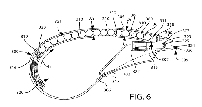
[0046] Referring to Figures 5 and 6, the dispenser 300 will be described in
more detail. The
dispenser 300 generally comprises a housing 309 having an internal cavity 320
and an internal
chamber 321. The housing 309 has an outer surface 301 and a nozzle 303.
Furthermore, the
dispenser 300 comprises an actuator 302 that extends from a bottom wall 306 of
the dispenser
300 and into the internal cavity 320. The internal cavity 320 is an empty
space that provides
room for the actuator 302 to extend into the housing 309 when the actuator 302
is activated as
will be described in detail below. The dispenser 300 is preferably formed of a
rigid plastic
material, such as without limitation polyethylene, polypropylene, polyester or
polyvinylidene
chloride. Of course, other materials can be used for the dispenser 300 as
would be known to
persons skilled in the art.
[0047] Referring now solely to Figure 5, the outer surface 301 of the
dispenser 300 comprises a
window 304 so that a user can view the contents contained in the internal
chamber 321 and/or
the internal cavity 320 of the dispenser 300. In certain embodiments, the
window 304 enables a
user to view the contents contained within the internal chamber 321 only. In
the exemplified
embodiment, the window 304 provides visual access into a portion of the
internal chamber 321
and a portion of the internal cavity 320. The window 304 is preferably a
transparent material
that can be clearly seen through so that the internal chamber 321 and/or
internal cavity 320 is
clearly viewable through the housing 309. However, in certain other
embodiments, the window
CA 02820187 2013-08-05
WO 2012/082119 PCT/US2010/060534
304 may be an opaque or translucent material. It should be understood that the
term "transparent
material" is intended to mean any type of material that enables a user to see
through the material,
even if the material is colored or somewhat difficult to see through. The
window 304 is position
on the outer surface 301 of the dispenser 300 so that capsules 310 that are
contained in the
internal chamber 321 and/or internal cavity 320 of the dispenser 300 can be
viewed from outside
of the dispenser 300.
[0048] The housing 309 of the dispenser 300 comprises a top wall 305 and the
bottom wall 306.
The shape of the dispenser 300 is particularly designed to be comfortably held
within a single
hand of a user. In the exemplified embodiment, the dispenser 300 has a
teardrop shape. Of
course, the invention is not so limited and the dispenser 300 may take on
other shapes as would
be known to persons skilled in the art. The actuator 302 extends from the
bottom wall 306 of the
dispenser 300 through an opening (not shown). Thus, if a user applies pressure
to the actuator
302 as will be described in more detail below, the actuator 302 will move
through the opening so
as to be fully contained within the internal cavity 320 of the dispenser 300.
[0049] The nozzle 303 is the portion of the dispenser 300 through which the
capsules 310 exit
the dispenser 300 so as to be inserted into the depression 230 of the oral
care implement 200. In
certain embodiments, the nozzle 303 is sized and shaped to be inserted into
the depression 230 of
the oral care implement 200. In this way, the nozzle 303 can be positioned
within the depression
230, and then one of the capsules 310 can be dispensed directly into the
depression 230. Due to
the flexible configuration of the prongs 231, inserting the capsules 310
directly into the
depression 230 as described above will result in the capsules 310 being
retained in the depression
230 until use. Dispensing of the capsules 310 will be described in more detail
below with
reference to Figure 6-9.
100501 As will also be described in more detail below with reference to
Figures 6-9, the
dispenser 300 may be hermetically sealed so as to prevent moisture from
entering into the
internal chamber 321 of the dispenser 300. The dispenser 300 is preferably
sealed in
embodiments where the dispenser 300 is designed to hold and dispense moisture
degradable
capsules 310 in order to prevent degradation. The details of the capsule 310
are described below.
[0051] In the exemplified embodiment, the capsules 310 are substantially
spherical beads. Of
course, the invention is not so limited and the capsules 310 may take on other
shapes as would be
known to persons skilled in the art. In one embodiment, the capsules 310
contain an oral care
material for treating or otherwise providing health benefits to a user's
teeth. In one specific
11
CA 02820187 2013-08-05
WO 2012/082119 PCT/US2010/060534
embodiment, the capsules 310 comprise a moisture degradable shell that
contains a fluidic oral
care material therein. The oral care material may be toothpowder, toothpaste,
tooth cleaning gel,
mouthwash or a similar dentifrice or oral hygiene product, or a combination of
the same. As
described above, during use, at least one of the capsule 310 is inserted into
the depression 230 of
the head 212 of the oral care implement 200. When a user uses the oral care
implement 200 to
brush his or her teeth, the capsule 310 ruptures thereby expelling its
contents (i.e., oral care
material) and providing health benefits to a user's teeth.
[0052] The capsules 310, or at least the shell of the capsules 310, are
moisture-sensitive and
should be protected against high humidity environments in order to prevent
premature rupture.
In other words, the capsules 310, or at least a portion thereof, are
susceptible to degradation
when subjected to a high humidity atmosphere as it has been discovered that
moisture in the air
in a high humidity environment can degrade the integrity of the capsules 310.
Therefore, the
capsules 310 must be packaged so as to be protected against moisture or
humidity in the air prior
to use. The dispenser 300 achieves this moisture-free environment as will be
described in more
detail below.
[0053] The capsules 310 hold and apply an oral care material onto the tooth
cleaning elements
222 of the oral care implement head 212, and ultimately to a user's teeth
and/or soft oral tissue
surfaces. In certain embodiments, the capsules 310 are liquid-filled gel
capsules having a shell
comprising frangible, thin walls that easily rupture or burst when rubbed
against the teeth. In a
preferred embodiment, the capsules 310 degrade when subjected to moisture and,
thus, dissolve
when mixed with the saliva of a user. As the saliva of a user degrades and
dissolves the walls of
the capsules 310, the oral care material held therein is excreted. While the
degradation of the
capsules 310 is a desired characteristic for effectuating end use of the oral
care implement 200 by
the consumer, the moisture-driven degradation of the capsules 310 presents
issues with respect to
properly preserving the integrity of the capsules 310 during product
manufacturing, packaging,
shipping and display in retail stores.
[0054] The capsules 310, or at least a portion thereof, are susceptible to
degradation when
subjected not only to direct contact with liquid water but also to prolonged
exposure to
atmospheres having a high humidity level. As noted above, it has been
discovered that a high
humidity environment can degrade the integrity of the capsules 310 and
prematurely expel the
oral care material or cause the oral care material to dry up. Of course, the
exact humidity levels
and exposure times that will result in the degradation of the capsules 310
will be determined on a
12
CA 02820187 2013-08-05
WO 2012/082119 PCT/US2010/060534
case-by-case basis, considering such factors as the type of capsule 310 being
used, the type of
oral care material, and the thermal cycling to which the oral care implement
200 is subjected. In
view of the foregoing, the capsules 310 are placed in the dispenser 300, which
forms a
hermetically sealed cavity, thereby protecting the capsules 310 from external
moisture which can
be in the form of a high humidity atmosphere or liquid water.
[0055] Referring now to FIGS. 6 to 10 concurrently, the internal components,
as well as the
dispensing capabilities, of the dispenser 300 will be described. Referring
first to Figure 6, the
dispenser 300 is illustrated with the actuator 302 in a biased position such
that a portion of the
actuator 302 extends beyond the bottom wall 306 of the housing 309. The
dispenser 300
comprises the internal chamber 321, which contains a plurality of the capsules
310 therein. In
the exemplified embodiment, the internal chamber 321 is an elongated
passageway in which the
plurality of capsules 310 are arranged in a single file line.
[0056] In certain embodiments, the dispenser 300 can be used for an entire
tooth care regimen.
For example, the plurality of capsules 310 can comprise a first type of
capsules 360 comprising a
first oral care material and a second type of capsules 361 comprising a second
oral care material,
such that the first and second oral care materials are different. For example,
the first oral care
material could be a tooth whitening agent while the second oral care material
may be a tooth
sensitivity agent. Of course, other oral care materials can be used. For
example, suitable oral
care materials include whitening agents, including without limitation,
peroxide containing tooth
whitening compositions. Suitable peroxide containing tooth whitening
compositions are
disclosed in U.S. Patent Serial No. 11/403,372, filed April 13, 2006, to the
present assignee, the
entirety of which is hereby incorporated by reference. While a tooth whitening
agent is one of
the exemplified active agents in the present invention, any other suitable
other care agents can be
used with embodiments of the present invention and, thus, stored within the
capsules 310.
Contemplated oral care agents can be an active or non-active ingredient,
including without
limitation, antibacterial agents; oxidative or whitening agents; enamel
strengthening or repair
agents; tooth erosion preventing agents; anti-sensitivity ingredients; gum
health actives;
nutritional ingredients; tartar control or anti-stain ingredients; enzymes;
sensate ingredients;
flavors or flavor ingredients; breath freshening ingredients; oral malodor
reducing agents; anti-
attachment agents or sealants; diagnostic solutions; occluding agents; anti-
inflammatory agents;
dry mouth relief ingredients; catalysts to enhance the activity of any of
these agents; colorants or
aesthetic ingredients; and combinations thereof. The oral care agent in one
embodiment is free
13
CA 02820187 2013-08-05
WO 2012/082119 PCT/US2010/060534
of (i.e., is not) toothpaste. Instead, the active agent is intended to provide
supplemental oral care
benefits in addition to merely brushing one's teeth. Other suitable oral care
agents could include
lip balm or other materials that are typically available in a semi-solid
state.
[0057] The plurality of capsules 310 can be arranged in the single file line
so that the first and
second types of capsules 360, 361 are in an alternating order. In this way, a
user can use the first
type of capsule 360, which may contain a dentifrice, for a normal
toothbrushing. Immediately
after completing toothbrushing with the first type of capsule 360, a user can
dispense the second
type of capsule 361 onto the oral care implement 200. The second type of
capsule 361 may
contain an agent, such as a whitening agent, an antibacterial agent, a
sensitivity agent, a tooth
strengthening agent or the like. The type of agent used as the first and
second oral care agents
are not limiting of the present invention and any agents may be used as would
be known to
persons skilled in the art. Furthermore, more than two different types of
capsules may be used so
that the tooth care regimen can include using three or more capsules having
different oral care
materials disposed therein in succession. Additionally, in certain embodiments
where the
depression 230 of the head 212 of the oral care implement 200 is sized to
accommodate two or
more capsules 310 at a time, two or more capsules containing oral care agents
that react when
combined to create a more effective cleaning solution may be used together.
[0058] Referring solely now FIG. 6, the internal chamber 321 of the dispenser
300 is defined
between the top wall 305 of the housing 309 and a chamber wall 312. Thus, the
internal
chamber 321 has a width Wi defined by the space between the top wall 305 of
the housing 309
and the chamber wall 312. The width Wi is the same as or slightly larger than
a diameter Di of
the capsules 310. It should be understood that the width Wi of the internal
chamber 321 should
be slightly larger than the diameter Di of the capsules 310 to enable the
capsules 310 to move
within the internal chamber 321 while only enabling a single file line of the
capsules 310 to fit
within the internal chamber 321. Furthermore, the internal chamber 321 has an
opening 307 that
creates a passageway from the internal chamber 321 to a dispensing conduit
322.
[0059] The dispensing conduit 322 extends from the internal chamber 321 to an
exterior 399 of
the dispenser 300. The dispensing conduit 322 comprises a loading zone 323
into which one
capsule 311 of the plurality of capsules 310 will be biased upon activation of
the actuator 302 as
will be described in more detail below. The dispensing conduit 322 further
comprises a
dispensing zone 324 that is positioned on the opposite side of a valve 325
relative to the loading
zone 323. After the capsule 310 passes through the valve 325, as will be
described in detail
14
CA 02820187 2013-08-05
WO 2012/082119 PCT/US2010/060534
below, the capsule 310 is positioned within the dispensing zone 324. Once in
the dispensing
zone 324, the capsule 310 can exit the dispenser through a nozzle opening 326
and be placed
within the depression 230 of the oral care implement 200.
[0060] As noted above, the valve 325 divides the dispensing conduit 322 into a
loading zone 323
and a dispensing zone 324. The valve 325 is preferably formed of an
elastomeric, rubber or
other flexible material such that the valve 325 opens in response to pressure
exerted in a
direction from the loading zone 323 to the dispensing zone 324. Thus, in
response to the
pressure as described above, the valve 325 allows the one capsule 311 of the
plurality of capsules
310 to pass from the loading zone 323 to the dispensing zone 324 for insertion
onto the oral care
implement 200. In the exemplified embodiment, the valve 325 is a one-way duck-
bill valve.
Thus, in its normal, biased state, the valve 325 is closed and creates a
hermetic seal. Stated
simply, in its biased position, moisture is unable to penetrate through the
valve 325 to enter into
the internal chamber 321 of the dispenser 300 through the dispensing conduit
322. Thus, the
valve 325 protects the capsules 310 positioned within the internal chamber 321
against moisture
degradation.
[0061] The dispenser 300 further comprises a dispensing subassembly comprising
the actuator
302, a drive mechanism 315, a first resilient member 316 and a second
resilient member 317. In
the exemplified embodiment, the first resilient member 316 is a helical or
coil spring and the
second resilient member 317 is a torsion spring. Of course, the invention is
not so limited and
the first and second resilient members 316, 317 may be other members or
objects that store
mechanical energy. For example, either of the first and second resilient
members 316, 317 may
be, without limitation, tension springs, compression springs, torsion springs,
coil springs, flat
springs, cantilever springs, balance springs, leaf springs or the like.
[0062] The second resilient member 317 is operably coupled to the actuator 302
and biases the
actuator 302 into a non-activated stated. In the non-activated state, a
portion of the actuator 302
extends from the bottom wall 306 of the housing 309. Furthermore, in the non-
activated state,
the drive mechanism 315 is positioned within the loading zone 323 of the
dispensing conduit 322
so as to prevent any of the plurality of capsules 310 from entering the
dispensing conduit 322
from the internal chamber 321. In other words, in the non-activated state, the
opening 307 of the
internal chamber 321 is closed by a top edge 318 of the drive mechanism 315.
By fully
enclosing the internal chamber 321, the capsules 310 provided in the internal
chamber 321 are
further protected against potential moisture degradation. Furthermore, the top
edge 318 of the
CA 02820187 2013-08-05
WO 2012/082119 PCT/US2010/060534
drive mechanism 315 can be covered by a grommet or gasket to further protect
the capsules 321
in the internal chamber 321 against moisture by preventing moisture from
entering the internal
chamber 321.
[0063] The first resilient member 316 imparts a loading force LF onto the
plurality of capsules
310. In the exemplified embodiment, the coil spring presses against the
plurality of capsules 310
and forces the plurality of capsules 310 towards the opening 307. The first
resilient member 316
includes a contact member 319 that is in continuous contact with a last
capsule 328 of the
plurality of capsules 310. The contact member 319 is formed of a soft, smooth
material, such as
an elastomer, rubber or the like. By forming the contact member 319 of a soft,
smooth material,
the first resilient member 316 will not prematurely rupture the last capsule
328 of the plurality of
capsules 310. As noted above, when the actuator 302 is in the biased non-
activated state, the
opening 307 is closed by the top edge 318 of the drive mechanism 315. As such,
in the non-
activated state, the first resilient member 316 contains potential energy that
will be converted to
kinetic energy upon activation of the actuator 302 as will be described in
more detail below.
[0064] Referring to FIGS. 7 and 8 concurrently, activation of the actuator 302
will be described.
The actuator 302 comprises slots 334, 335 through which protrusions 336
(second protrusion not
shown) of the drive mechanism 315 extend. As the actuator 302 is activated by
a user, as will be
described below, the protrusions 336 of the drive mechanism 315 slide within
the slots 334, 335
of the actuator 302, which in turn moves the drive mechanism 315 within the
dispensing conduit
322.
[0065] In FIG. 7, a force F1 is applied to the actuator 302. The force F1 can
be applied to the
actuator 302 by a user gripping the actuator 302 with his or her fingers and
having the user's
palm resting against the top wall 305 of the dispenser 300. Of course, the
invention is not so
limited and the force Ft can be applied by other methods so long as the
actuator 302 is forced
into the internal cavity 320. When the user squeezes his or her fingers in the
direction of the
arrow F1, the actuator 302 pivots along a pivot point 341. Upon application of
the force F1 to the
actuator 302, the entire actuator 302 will be positioned within the internal
cavity 320 of the
dispenser 300. Additionally, the protrusions 336 of the drive mechanism 315
will slide within
the slots 334, 335 of the actuator 302, which causes the drive mechanism 315
to slide within the
dispensing conduit 322 in a direction away from the valve 325.
[0066] As can be seen in FIG. 7, when the drive mechanism 315 slides within
the dispensing
conduit 322 in a direction away from the valve 325, the opening 307 in the
internal chamber 321
16
CA 02820187 2013-08-05
WO 2012/082119 PCT/US2010/060534
is exposed, thereby forming a passageway from the internal chamber 321 to the
dispensing
conduit 322.
[0067] As can be seen in FIG. 8, when the opening 307 in the internal chamber
321 is
unobstructed, the one capsule 311 of the plurality of capsules 310 drops into
the loading zone
323 of the dispensing conduit 322. This occurs because the first resilient
member 316 is
continuously imparting the loading force LF onto the plurality of capsules
310. As a result, when
the opening 307 in the internal chamber 321 becomes unobstructed, thereby
forming a
passageway from the internal chamber 321 to the loading zone 323, the loading
force LF forces
the plurality of capsules 310 to move towards the opening 307. Because the one
capsule 311 of
the plurality of capsules 310 is nearest to the opening 307, the one capsule
311 enters into the
loading zone 323 of the dispensing conduit 322.
[0068] The dispensing conduit 322 has a width Wm. The width Wm of the
dispensing conduit
322 is the same as, or slightly larger than the diameter DI of the plurality
of capsules 310. As
such, only one of the plurality of capsules 310 is able to fit within the
dispensing conduit 322 at
one time. This enables the dispenser 300 to dispense a single capsule of the
plurality of capsules
311 at a time. In certain embodiments, it may be desirable to dispense more
than a single
capsule at a time. In such embodiments, the dispensing conduit 322 may have a
larger width in
order to accommodate two or more capsules therein at a time.
[0069] The drive mechanism 315 comprises an engagement surface 337. The
engagement
surface 337 of the drive mechanism 315 is a concave surface that corresponds
to the size and
shape of the capsules 310. In certain embodiments, the engagement surface 337
of the drive
mechanism 315 is formed of or covered with a soft, elastomeric material. The
shape and
material of the engagement surface 337 of the drive mechanism 315 are designed
so that the
capsules 310 are not ruptured during dispensing. In other words, as will be
described below,
during dispensing the drive mechanism 315 contacts the one capsule 311 to push
it through the
valve 325. Thus, by forming the engagement surface 337 of the drive mechanism
315 with the
shape and material as discussed above, premature rupture of the one capsule
311 during
dispensing is prevented. Of course, such a cushioning structure may be omitted
if desired.
100701 Referring to FIGS. 9 and 10 concurrently, the dispensing of the one
capsule 311 of the
plurality of capsules 310 from the dispensing conduit 322 will be described.
After the one
capsule 311 of the plurality of capsules 310 becomes positioned within the
loading zone 323 of
the dispensing conduit 322, the user releases the actuator 302. As described
above, the actuator
17
CA 02820187 2013-08-05
WO 2012/082119 PCT/US2010/060534
302 is biased into a non-activated state. As such, when the user releases the
actuator 302 by the
cessation of the force F1 to the actuator 302, the actuator 302 extends back
beyond the bottom
wall 306 of the housing 309 of the dispenser 300 in the direction of the arrow
B1. The second
resilient member 317 biases the actuator 302 back into the non-activated state
as soon as the
force F1 is no longer applied.
[0071] Upon biasing the actuator 302 into the non-activated state, the
protrusions 336 of the
drive mechanism 315 slide within the slots 334, 335 of the actuator 302 in the
direction of the
valve 325. Thus, the drive mechanism 315 imparts a dispensing force DF onto
the one capsule
311 in the direction of the arrow. The dispensing force DF of the drive
mechanism 315 is
imparted onto the one capsule 311 of the plurality of capsules 310, which
pushes the one capsule
311 towards the valve 325. As the one capsule 311 is driven towards the valve
325, the valve
325 is forced into an open state whereby an opening 342 in the valve 325
creates a passageway
from the loading zone 323 to the dispensing zone 324.
[0072] As the drive mechanism 315 drives the one capsule 311 through the
opening 342 in the
valve 325, the top edge 318 of the drive mechanism 315 blocks the opening 307
of the internal
chamber 321. As such, while the one capsule 311 is being dispensed, the
plurality of capsules
310 are prevented from entering into the dispensing conduit 322 from the
internal chamber 322.
[0073] Referring now to FIG. 10, as the drive mechanism 315 continues to apply
the dispensing
force DF to the one capsule 311, the one capsule 311 passes completely through
the valve 325
into the dispensing zone 324. As the one capsule 311 passes through the
opening 342 in the
valve 325, the valve 325 automatically closes the opening 342 and returns to a
sealed state so as
to prevent moisture from entering into the internal chamber 321 through the
dispensing conduit
322.
[0074] Once in the dispensing zone 324, the one capsule 311 can easily be
removed from the
dispenser 300 through the nozzle opening 326. In certain embodiments as
discussed above, the
nozzle 303 is sized and shaped to be inserted into the depression 230 of the
oral care implement
200. In such embodiments, the dispensing force DF may be equal to or greater
than a force
required to operably insert the one capsule 311 into the depression 230
through the prongs 231.
As such, the nozzle 303 can simply be aligned with or inserted into the
depression 230 in the
head 214 of the oral care implement 200 and the actuator 302 activated to
properly position the
one capsule 311 in the depression 230 to be retained by the prongs 231.
18
CA 02820187 2013-08-05
WO 2012/082119 PCT/US2010/060534
[0075] Referring again to FIGS. 6 to 10 concurrently, a method of applying
oral care material to
an oral surface will be described. In performing the method, one of the oral
care implements 200
and the dispenser 300 described above will be provided (i.e., obtained by a
user). The dispenser
300 is positioned adjacent the oral care implement 200 so that one of the
plurality of capsules
310 can be dispensed from the dispenser 300 and disposed on the oral care
implement 200.
Specifically, the dispenser 300 is positioned adjacent the oral care implement
200 so that the
nozzle 303 is positioned within the depression 230 of the oral care implement
200. The
dispenser 300 is then activated as described above to impart the dispensing
force FD onto the one
capsule 311 of the plurality of capsules 310, thereby forcing the one capsule
10 through the valve
325 and onto the oral care implement 200. In preferred embodiments, the
dispensing force FD is
equal to or greater than a force required to operably insert the one capsule
311 into the prongs
231 of the oral care implement 200.
[0076] As used throughout, ranges are used as shorthand for describing each
and every value
that is within the range. Any value within the range can be selected as the
terminus of the range.
In addition, all references cited herein are hereby incorporated by reference
in their entireties. In
the event of a conflict in a definition in the present disclosure and that of
a cited reference, the
present disclosure controls.
19