Note: Descriptions are shown in the official language in which they were submitted.
CA 02825364 2013-07-22
WO 2012/107731 PCT/GB2012/000141
- I -
SYSTEM AND METHOD FOR SERVICING A WELLBORE
BACKGROUND
[0001] Subterranean formations that contain hydrocarbons are sometimes non-
homogeneous in their composition along the length of wellbores that extend
into such
formations. It is sometimes desirable to treat and/or otherwise manage the
formation and/or the
wellbore differently in response to the differing formation composition. Some
wellbore
servicing systems and methods allow such treatment, referred to by some as
zonal isolation
treatments. However, in some wellbore servicing systems and methods, while
multiple tools for
use in treating zones may be activated by a single obturator, such activation
of one tool by the
obturator may cause activation of additional tools to be more difficult. For
example, a ball may
be used to activate a plurality of stimulation tools, thereby allowing fluid
communication
between a flow bore of the tools with a space exterior to the tools. However,
such fluid
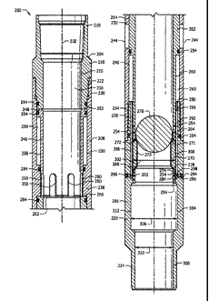
communication accomplished by activated tools may increase the working
pressure required to
subsequently activate additional tools. Accordingly, there exists a need for
improved systems
and methods of treating multiple zones of a wellbore.
SUMMARY
[0002] According to one aspect of the present invention, there is provided
a wellbore
servicing system, comprising a first sleeve system, the first sleeve system
comprising a first
ported case, a first sliding sleeve at least partially carried within the
first ported case and
movable relative to the first ported case between a first sleeve position in
which the first sliding
sleeve restricts fluid communication via the ported case and a second sleeve
position in which
the first sliding sleeve does not restrict fluid communication via the ported
case, a first
segmented seat, the first segmented seat being radially divided into a
plurality of segments and
movable relative to the first ported case between a first seat position in
which the first seat
CA 02825364 2013-07-22
WO 2012/107731 PCT/GB2012/000141
- 2 -
restricts movement of the sliding sleeve relative to the ported case and a
second seat position in
which the first seat does not restrict movement of the sliding sleeve relative
to the ported case,
and a first sheath forming a continuous layer that covers one or more surfaces
of the first
segmented seat, the first sleeve system being transitionable from a first mode
to a second mode
and transitionable from the second mode to a third mode, wherein, when in the
first mode, the
first sliding sleeve is retained in the first sleeve position and the first
segmented seat is retained
in the first seat position, wherein, when in the second mode, the first
sliding sleeve is retained in
the first sleeve position and the first segmented seat is in the second seat
position, and wherein,
when in the third mode, the first sliding sleeve is in the second sleeve
position.
100031 In another aspect, there is also provided a wellbore servicing
method comprising
positioning a first sleeve system within the wellbore proximate to a first
treatment zone, the first
sleeve system comprising a first ported case, a first sliding sleeve at least
partially carried within
the first ported case and movable relative to the first ported case between a
first sleeve position
in which the first sliding sleeve restricts fluid communication via the ported
case and a second
sleeve position in which the first sliding sleeve does not restrict fluid
communication via the
ported case, a first segmented seat, the first segmented seat being radially
divided into a plurality
of segments and movable relative to the first ported case between a first seat
position in which
the first seat restricts movement of the sliding sleeve relative to the ported
case and a second
seat position in which the first seat does not restrict movement of the
sliding sleeve relative to
the ported case, and a first sheath forming a continuous layer that covers one
or more surfaces of
the first segmented seat, the first sleeve system being transitionable from a
first mode to a
second mode and transitionable from the second mode to a third mode, wherein,
when in the
first mode, the first sliding sleeve is retained in the first sleeve position
and the first segmented
seat is retained in the first seat position, wherein, when in the second mode,
the first sliding
CA 02825364 2013-07-22
WO 2012/107731 PCT/GB2012/000141
- 3 -
sleeve is retained in the first sleeve position and the first segmented seat
is in the second seat
position, and wherein, when in the third mode, the first sliding sleeve is in
the second sleeve
position.
BRIEF DESCRIPTION OF THE DRAWINGS
[0004] For a more complete understanding of the present disclosure and the
advantages
thereof, reference is now made to the following brief description, taken in
connection with the
accompanying drawings and detailed description:
[0005] Figure 1 is a cut-away view of an embodiment of a wellbore servicing
system
according to the disclosure;
[0006] Figure 2 is a cross-sectional view of a sleeve system of the
wellbore servicing
system of Figure 1 showing the sleeve system in an installation mode;
[0007] Figure 2A is a cross-sectional end-view of a segmented seat of the
sleeve system of
Figure 2 showing the segmented seat divided into three segments;
[0008] Figure 2B is a cross-sectional view of a segmented seat of the
sleeve system of
Figure 2 having a protective sheath applied thereto;
[0009] Figure 3 is a cross-sectional view of the sleeve system of Figure 2
showing the
sleeve system in a delay mode;
[0010] Figure 4 is a cross-sectional view of the sleeve system of Figure 2
showing the
sleeve system in a fully open mode;
[0011] Figure 5 is a cross-sectional view of an alternative embodiment of a
sleeve system
according to the disclosure showing the sleeve system in an installation mode;
[0012] Figure 6 is a cross-sectional view of the sleeve system of Figure 5
showing the
sleeve system in another stage of the installation mode;
CA 02825364 2013-07-22
WO 2012/107731
PCT/GB2012/000141
- 4 -
[0013] Figure 7
is a cross-sectional view of the sleeve system of Figure 5 showing the
sleeve system in a delay mode; and
[0014] Figure 8
is a cross-sectional view of the sleeve system of Figure 5 showing the
sleeve system in a fully open mode.
DETAILED DESCRIPTION OF THE EMBODIMENTS
[00151 In the
drawings and description that follow, like parts are typically marked
throughout the specification and drawings with the same reference numerals,
respectively. The
drawing figures are not necessarily to scale. Certain features of the
invention may be shown
exaggerated in scale or in somewhat schematic form and some details of
conventional elements
may not be shown in the interest of clarity and conciseness.
[0016] Unless
otherwise specified, any use of any form of the terms "connect," "engage,"
"couple," "attach," or any other term describing an interaction between
elements is not meant to
limit the interaction to direct interaction between the elements and may also
include indirect
interaction between the elements described. In the following discussion and in
the claims, the
terms "including" and "comprising" are used in an open-ended fashion, and thus
should be
interpreted to mean "including, but not limited to ...." Reference to up or
down will be made
for purposes of description with "up," "upper," "upward," or "upstream"
meaning toward the
surface of the wellbore and with "down," "lower," "downward," or "downstream"
meaning
toward the terminal end of the well, regardless of the wellbore orientation.
The term "zone" or
"pay zone" as used herein refers to separate parts of the wellbore designated
for treatment or
production and may refer to an entire hydrocarbon formation or separate
portions of a single
formation such as horizontally and/or vertically spaced portions of the same
formation. The
various characteristics mentioned above, as well as other features and
characteristics described
in more detail below, will be readily apparent to those skilled in the art
with the aid of this
CA 02825364 2013-07-22
WO 2012/107731 PCT/GB2012/000141
- 5 -
disclosure upon reading the following detailed description of the embodiments
and by referring
to the accompanying drawings.
[0017] Disclosed herein are improved components, more specifically, a
sheathed,
segmented seat, for use in downhole tools. Such a sheathed, segmented seat may
be
employed alone or in combination with other components to transition one or
more downhole
tools from a first configuration to a second, third, or fourth, etc.
configuration or mode by
selectively receiving, retaining, and releasing an obturator (or any other
suitable actuator or
actuating device).
[0018] Also disclosed herein are sleeve systems and methods of using
downhole tools,
more specifically sleeve systems employing a sheathed, segmented seat that may
be placed in
a wellbore in a "run-in" configuration or an "installation mode" where a
sleeve of the sleeve
system blocks fluid transfer between a flow bore of the sleeve system and a
port of the sleeve
system. The installation mode may also be referred to as a "locked mode" since
the sleeve is
selectively locked in position relative to the port. In some embodiments, the
locked
positional relationship between the sleeves and the ports may be selectively
discontinued or
disabled by unlocking one or more components relative to each other, thereby
potentially
allowing movement of the sleeves relative to the ports. Still further, once
the components are
no longer locked in position relative to each other, some of the embodiments
are configured
to thereafter operate in a "delay mode" where relative movement between the
sleeve and the
port is delayed insofar as (1) such relative movement occurs but occurs at a
reduced and/or
controlled rate and/or (2) such relative movement is delayed until the
occurrence of a selected
wellbore condition. The delay mode may also be referred to as an "unlocked
mode" since the
sleeves are no longer locked in position relative to the ports. In some
embodiments, the
sleeve systems may be operated in the delay mode until the sleeve system
achieves a "fully
CA 02825364 2013-07-22
WO 2012/107731 PCT/GB2012/000141
- 6 -
open mode" where the sleeve has moved relative to the port to allow maximum
fluid
communication between the flow bore of the sleeve system and the port of the
sleeve system.
It will be appreciated that devices, systems, and/or components of sleeve
system
embodiments that selectively contribute to establishing and/or maintaining the
locked mode
may be referred to as locking devices, locking systems, locks, movement
restrictors,
restrictors, and the like. It will also be appreciated that devices, systems,
and/or components
of sleeve system embodiments that selectively contribute to establishing
and/or maintaining
the delay mode may be referred to as delay devices, delay systems, delays,
timers, contingent
openers, and the like.
100191 Also disclosed herein are methods for configuring a plurality of
such sleeve
systems so that one or more sleeve systems may be selectively transitioned
from the
installation mode to the delay mode by passing a single obturator through the
plurality of
sleeve systems. As will be explained below in greater detail, in some
embodiments, one or
more sleeve systems may be configured to interact with an obturator of a first
configuration
while other sleeve systems may be configured not to interact with the
obturator having the
first configuration, but rather, configured to interact with an obturator
having a second
configuration. Such differences in configurations amongst the various sleeve
systems may
allow an operator to selectively transition some sleeve systems to the
exclusion of other
sleeve systems.
[0020] Also disclosed herein are methods for performing a wellbore
servicing operation
employing a plurality of such sleeve systems by configuring such sleeve
systems so that one
or more of the sleeve systems may be selectively transitioned from the delay
mode to the fully
open mode at varying time intervals. Such differences in configurations
amongst the various
sleeve systems may allow an operator to selectively transition some sleeve
systems to the
CA 02825364 2013-07-22
WO 2012/107731 PCT/GB2012/000141
- 7 -
exclusion of other sleeve systems, for example, such that a servicing fluid
may be
communicated (e.g., for the performance of a servicing operation) via a first
sleeve system
while not being communicated via a second, third, fourth, etc. sleeve system.
The following
discussion describes various embodiments of sleeve systems, the physical
operation of the
sleeve systems individually, and methods of servicing wellbores using such
sleeve systems.
[0021] Referring to Figure 1, an embodiment of a wellbore servicing system
100 is shown
in an example of an operating environment. As depicted, the operating
environment
comprises a servicing rig 106 (e.g., a drilling, completion, or workover rig)
that is positioned
on the earth's surface 104 and extends over and around a wellbore 114 that
penetrates a
subterranean formation 102 for the purpose of recovering hydrocarbons. The
wellbore 114
may be drilled into the subterranean formation 102 using any suitable drilling
technique. The
wellbore 114 extends substantially vertically away from the earth's surface
104 over a vertical
wellbore portion 116, deviates from vertical relative to the earth's surface
104 over a deviated
wellbore portion 136, and transitions to a horizontal wellbore portion 118. In
alternative
operating environments, all or portions of a wellbore may be vertical,
deviated at any suitable
angle, horizontal, and/or curved.
[0022] At least a portion of the vertical wellbore portion 116 is lined
with a casing 120
that is secured into position against the subterranean formation 102 in a
conventional manner
using cement 122. In alternative operating environments, a horizontal wellbore
portion may
be cased and cemented and/or portions of the wellbore may be uncased. The
servicing rig
106 comprises a derrick 108 with a rig floor 110 through which a tubing or
work string 112
(e.g., cable, wireline, E-line, Z-line, jointed pipe, coiled tubing, casing,
or liner string, etc.)
extends downward from the servicing rig 106 into the wellbore 114 and defines
an annulus
128 between the work string 112 and the wellbore 114. The work string 112
delivers the
CA 02825364 2013-07-22
WO 2012/107731
PCT/GB2012/000141
- 8 -
wellbore servicing system 100 to a selected depth within the wellbore 114 to
perform an
operation such as perforating the casing 120 and/or subterranean formation
102, creating
perforation tunnels and/or fractures (e.g., dominant fractures, micro-
fractures, etc.) within the
subterranean formation 102, producing hydrocarbons from the subterranean
formation 102,
and/or other completion operations. The servicing rig 106 comprises a motor
driven winch
and other associated equipment for extending the work string 112 into the
wellbore 114 to
position the wellbore servicing system 100 at the selected depth.
[0023] While the
operating environment depicted in Figure 1 refers to a stationary servicing
rig 106 for lowering and setting the wellbore servicing system 100 within a
land-based
wellbore 114, in alternative embodiments, mobile workover rigs, wellbore
servicing units (such
as coiled tubing units), and the like may be used to lower a wellbore
servicing system into a
wellbore. It should be understood that a wellbore servicing system may
alternatively be used in
other operational environments, such as within an offshore wellbore
operational environment.
10024] The
subterranean formation 102 comprises a zone 150 associated with deviated
wellbore portion 136. The subterranean formation 102 further comprises first,
second, third,
fourth, and fifth horizontal zones, 150a, 150b, 150c, 150d, 150e,
respectively, associated with
the horizontal wellbore portion 118. In this embodiment, the zones 150, 150a,
150b, 150c,
150d, 150e are offset from each other along the length of the wellbore 114 in
the following
order of increasingly downhole location: 150, 150e, 150d, 150c, 150b, and
150a. In this
embodiment, stimulation and production sleeve systems 200, 200a, 200b, 200c,
200d, and
200e are located within wellbore 114 in the work string 112 and are associated
with zones
150, 150a, 150h, 150c, 150d, and 150e, respectively. It will be appreciated
that zone isolation
devices such as annular isolation devices (e.g., annular packers and/or
swellpackers) may be
CA 02825364 2013-07-22
WO 2012/107731
PCT/GB2012/000141
- 9 -
selectively disposed within wellbore 114 in a manner that restricts fluid
communication
between spaces immediately uphole and downhole of each annular isolation
device.
100251 Referring
now to Figure 2, a cross-sectional view of an embodiment of a
stimulation and production sleeve system 200 (hereinafter referred to as
"sleeve system" 200)
is shown. Many of the components of sleeve system 200 lie substantially
coaxial with a
central axis 202 of sleeve system 200. Sleeve system 200 comprises an upper
adapter 204, a
lower adapter 206, and a ported case 208. The ported case 208 is joined
between the upper
adapter 204 and the lower adapter 206. Together, inner surfaces 210, 212, 214
of the upper
adapter 204, the lower adapter 206, and the ported case 208, respectively,
substantially define
a sleeve flow bore 216. The upper adapter 204 comprises a collar 218, a makeup
portion 220,
and a case interface 222. The collar 218 is internally threaded and otherwise
configured for
attachment to an element of work string 112 that is adjacent and uphole of
sleeve system 200
while the case interface 222 comprises external threads for engaging the
ported case 208. The
lower adapter 206 comprises a nipple 224, a makeup portion 226, and a case
interface 228.
The nipple 224 is externally threaded and otherwise configured for attachment
to an element
of work string 112 that is adjacent and downhole of sleeve system 200 while
the case
interface 228 also comprises external threads for engaging the ported case
208.
[00261 The ported
case 208 is substantially tubular in shape and comprises an upper
adapter interface 230, a central ported body 232, and a lower adapter
interface 234, each
having substantially the same exterior diameters. The inner surface 214 of
ported case 208
comprises a case shoulder 236 that separates an upper inner surface 238 from a
lower inner
surface 240. The ported case 208 further comprises ports 244. As will be
explained in
further detail below, ports 244 are through holes extending radially through
the ported case
CA 02825364 2013-07-22
WO 2012/107731 PCT/GB2012/000141
-10-
208 and are selectively used to provide fluid communication between sleeve
flow bore 216
and a space immediately exterior to the ported case 208.
[0027] The sleeve system 200 further comprises a piston 246 carried within
the ported
case 208. The piston 246 is substantially configured as a tube comprising an
upper seal
shoulder 248 and a plurality of slots 250 near a. lower end 252 of the piston
246. With the
exception of upper seal shoulder 248, the piston 246 comprises an outer
diameter smaller than
the diameter of the upper inner surface 238. The upper seal shoulder 248
carries a
circumferential seal 254 that provides a fluid tight seal between the upper
seal shoulder 248
and the upper inner surface 238. Further, case shoulder 236 carries a seal 254
that provides a
fluid tight seal between the case shoulder 236 and an outer surface 256 of
piston 246. In the
embodiment shown and when the sleeve system 200 is configured in an
installation mode, the
upper seal shoulder 248 of the piston 246 abuts the upper adapter 204. The
piston 246
extends from the upper seal shoulder 248 toward the lower adapter 206 so that
the slots 250
are located downhole of the seal 254 carried by case shoulder 236. In this
embodiment, the
portion of the piston 246 between the seal 254 carried by case shoulder 236
and the seal 254
carried by the upper seal shoulder 248 comprises no apertures in the tubular
wall (i.e., is a
solid, fluid tight wall). As shown in this embodiment and in the installation
mode of Figure
2, a low pressure chamber 258 is located between the outer surface 256 of
piston 246 and the
upper inner surface 238 of the ported case 208.
[0028] The sleeve system 200 further comprises a sleeve 260 carried within
the ported
case 208 below the piston 246. The sleeve 260 is substantially configured as a
tube
comprising an upper seal shoulder 262. With the exception of upper seal
shoulder 262, the
sleeve 260 comprises an outer diameter substantially smaller than the diameter
of the lower
inner surface 240. The upper seal shoulder 262 carries two circumferential
seals 254, one
CA 02825364 2013-07-22
WO 2012/107731 PCT/GB2012/000141
- 11 -
seal 254 near each end (e.g., upper and lower ends) of the upper seal shoulder
262, that
provide fluid tight seals between the upper seal shoulder 262 and the lower
inner surface 240
of ported case 208. Further, two seals 254 are carried by the sleeve 260 near
a lower end 264
of sleeve 260, and the two seals 254 form fluid tight seals between the sleeve
260 and the
inner surface 212 of the lower adapter 206. In this embodiment and
installation mode shown
in Figure 2, an upper end 266 of sleeve 260 substantially abuts a lower end of
the case
shoulder 236 and the lower end 252 of piston 246. In this embodiment and
installation mode
shown in Figure 2, the upper seal shoulder 262 of the sleeve 260 seals ports
244 from fluid
communication with the sleeve flow bore 216. Further, the seal 254 carried
near the lower
end of the upper seal shoulder 262 is located downhole of (e.g., below) ports
244 while the
seal 254 carried near the upper end of the upper seal shoulder 262 is located
uphole of (e.g.,
above) ports 244. The portion of the sleeve 260 between the seal 254 carried
near the lower
end of the upper seal shoulder 262 and the seals 254 carried by the sleeve 260
near a lower
end 264 of sleeve 260 comprises no apertures in the tubular wall (i.e., is a
solid, fluid tight
wall). As shown in this embodiment and in the installation mode of Figure 2, a
fluid chamber
268 is located between the outer surface of sleeve 260 and the lower inner
surface 240 of the
ported case 208.
[0029] The sleeve system 200 further comprises a segmented seat 270 carried
within the
lower adapter 206 below the sleeve 260. The segmented seat 270 is
substantially configured
as a tube comprising an inner bore surface 273 and a chamfer 271 at the upper
end of the seat,
the chamfer 271 being configured and/or sized to selectively engage and/or
retain an obturator
of a particular size and/or shape (such as obturator 276). In the embodiment
of Figure 2, the
segmented seat 270 may be radially divided with respect to central axis 202
into segments.
For example, referring now to Figure 2A, the segmented seat 270 is divided
(e.g., as
CA 02825364 2013-07-22
WO 2012/107731 PCT/GB2012/000141
- 12 -
represented by dividing or segmenting lines/cuts 277) into three complementary
segments of
Approximately equal size, shape, and/or configuration. In the embodiment of
Figure 2A, the
three complementary segments (270A, 270B, and 270C, respectively) together
form the
segmented seat 270, with each of the segments (270A, 270B, and 270C)
constituting about
one-third (e.g., extending radially about 1200) of the segmented seat 270. In
an alternative
embodiment, a segmented seat like segmented seat 270 may comprise any suitable
number of
equally or unequally-divided segments. For example, a segmented seat may
comprise two,
four, five, six, or more complementary, radial segments. The segmented seat
270 may be
formed from a suitable material. Nonlimiting examples of such a suitable
material include
composites, phenolics, cast iron, aluminum, brass, various metal alloys,
rubbers, ceramics, or
combinations thereof. In an embodiment, the material employed to form the
segmented seat
may be characterized as drillable, that is, the segmented seat 270 may be
fully or partially
degraded or removed by drilling, as will be appreciated by one of skill in the
art with the aid
of this disclosure. Segments 270A, 270B, and 270C may be formed independently
or,
alternatively, a preformed seat may be divided into segments. It will be
appreciated that
while obturator 276 is shown in Figure 2 with the sleeve system 200 in an
installation mode,
in most applications of the sleeve system 200, the sleeve system 200 would be
placed
downhole without the obturator 276, and the obturator 276 would subsequently
be provided
as discussed below in greater detail. Further, while the obturator 276 is a
ball, an obturator of
other embodiments may be any other suitable shape or device for sealing
against a protective
sheath 272 and or a seat gasket (both of which will be discussed below) and
obstructing flow
through the sleeve flow bore 216.
[00301 In an alternative embodiment, a sleeve system like sleeve system 200
may
comprise an expandable seat. Such an expandable seat may be constructed of,
for example
CA 02825364 2013-07-22
WO 2012/107731 PCT/GB2012/000141
- 13 -
but not limited to, a low alloy steel such as AISI 4140 or 4130, and is
generally configured to
be biased radially outward so that if unrestricted radially, a diameter (e.g.,
outer/inner) of the
seat 270 increases. In some embodiments, the expandable seat may be
constructed from a
generally serpentine length of AISI 4140. For example, the expandable seat may
comprise a
plurality of serpentine loops between upper and lower portions of the seat and
continuing
circumferentially to form the seat. In an embodiment, such an expandable seat
may be
covered by a protective sheath 272 (as will be discussed below) and/or may
comprise a seat
gasket
[00311 In the embodiment of Figure 2, one or more surfaces of the segmented
seat 270 are
covered by a protective sheath 272. Referring to Figure 2B, an embodiment of
the segmented
seat 270 and protective sheath 272 are illustrated in greater detail. In the
embodiment of
Figure 2B the protective sheath 272 covers the chamfer 271 of the segmented
seat 270, the
inner bore 273 of the segmented seat 270, and a lower face 275 of the
segmented seat 270. In
an alternative embodiment, the protective sheath 272 may cover the chamfer
271, the inner
bore 273, and a lower face 275, the back 279 of the segmented seat 270, or
combinations
thereof. In another alternative embodiment, a protective sheath may cover any
one or more of
the surfaces of a segmented seat 270, as will be appreciated by one of skill
in the art viewing
this disclosure. In the embodiment illustrated by Figures 2, 2A, and 2B, the
protective sheath
272 forms a continuous layer over those surfaces of the segmented seat 270 in
fluid
communication with the sleeve flow bore 216. For example, small crevices or
gaps (e.g., at
dividing lines 277) may exist at the radially extending divisions between the
segments (e.g.,
270A, 270B, and 270C) of the segmented seat 270. In an embodiment, the
continuous layer
formed by the protective sheath 272 may fill, seal, minimize, or cover, any
such crevices or
CA 02825364 2013-07-22
WO 2012/107731
PCT/GB2012/000141
- 14 -
gaps such that a fluid flowing via the sleeve flow bore 216 will be impeded
from contacting
and/or penetrating any such crevices or gaps.
[0032] In an
embodiment, the protective sheath 272 may be applied to the segmented seat
270 while the segments 270A, 270B, and 270C are retained in a close
conformation (e.g.,
where each segment abuts the adjacent segments, as illustrated in Figure 2A).
For example,
the segmented seat 270 may be retained in such a close conformation by bands,
bindings,
straps, wrappings, or combinations thereof. In an embodiment, the segmented
seat 270 may
be coated and/or covered with the protective sheath 272 via any suitable
method of
application. For example, the segmented seat 270 may submerged (e.g., dipped)
in a material
(as will be discussed below) that will form the protective sheath 272, a
material that will form
the protective sheath 272 may be sprayed and/or brushed onto the desired
surfaces of the
segmented seat 270, or combinations thereof. In such an embodiment, the
protective sheath
270 may adhere to the segments 270A, 270B, and 270C of the segmented seat 270
and
thereby retain the segments in the close conformation.
[00331 In an
alternative embodiment, the protective sheath 272 may be applied
individually to each of the segments 270A, 270B, and 270C of the segmented
seat 270. For
example, the segments 270A, 270B, and/or 270C may individually submerged
(e.g., dipped)
in a material that will form the protective sheath 272, a material that will
form the protective
sheath 272 may be sprayed and/or brushed onto the desired surfaces of the
segments 270A,
270B, and 270C, or combinations thereof. In such an embodiment, the protective
sheath 272
may adhere to some or all of the surfaces of each of the segments 270A, 270B,
and 270C.
After the protective sheath 272 has been applied, the segments 270A, 270B, and
270C may be
brought together to form the segmented seat 270. The segmented seat 270 may be
retained in
such a close conformation (e.g., as illustrated in Figure 2A) by bands,
bindings, straps,
=
CA 02825364 2013-07-22
WO 2012/107731 PCT/GB2012/000141
- 15 -
wrappings, or combinations thereof. In such an embodiment, the protective
sheath 272 may
be sufficiently malleable or pliable that when the sheathed segments are
retained in the close
conformation, any crevices or gaps between the segments (e.g., segments 270A,
270B, and
270C) will be filled or minimized by the protective sheath 272 such that a
fluid flowing via
the sleeve flow bore 216 will be impeded from contacting and/or penetrating
any such
crevices or gaps.
[0034] In still another alternative embodiment, the protective sheath 272
need not be
applied directly to the segmented seat 270. For example, a protective sheath
may be fitted to
or within the segmented seat 270, draped over a portion of segmented seat 270,
or the like.
The protective sheath may comprise a sleeve or like insert configured and
sized to be
positioned within the bore of the segmented sheath and to fit against the
chamfer 271 of the
segmented seat 270, the inner bore 273 of the segmented seat 270, and/or the
lower face 275
of the segmented seat 270 and thereby form a continuous layer that may fill,
seal, or cover,
any such crevices or gaps such that a fluid flowing via the sleeve flow bore
216 will be
impeded from contacting and/or penetrating any such crevices or gaps. In
another
embodiment where the protective sheath 272 comprises a heat-shrinkable
material (as will be
discussed below), such a material may be positioned over, around, within,
about, or similarly,
at least a portion of the segmented seat 270 and/or one or more of the
segments 270A, 27013,
and 270C, and heated sufficiently to cause the shrinkable material to shrink
to the surfaces of
the segmented seat 270 and/or the segments 270A, 270B, and 270C.
[0035] In an embodiment, the protective sheath 272 may be formed from a
suitable
material. Nonlimiting examples of such a suitable material include ceramics,
carbides,
hardened plastics, molded rubbers, various heat-shrinkable materials, or
combinations
thereof. In an embodiment, the protective sheath may be characterized as
having a hardness
=
=
=
=
CA 02825364 2013-07-22
WO 2012/107731
PCT/GB2012/000141
- 16-.
of from about 25 durometers to about 150 durometers, alternatively, from about
50
durometers to about 100 durometers, alternatively, from about 60 durometers to
about 80
durometers. In an embodiment, the protective sheath may be characterized as
having a
thickness of from about 1/64th of an inch to about 3/16th of an inch,
alternatively, about 1132nd
of an inch. Examples of materials suitable for the formation of the protective
sheath include
nitrite rubber, which commercially available from several rubber, plastic,
and/or composite
materials companies.
[00361 In an
embodiment, a protective sheath, like protective sheath 272, may be
employed to advantageously lessen the degree of erosion and/or degradation to
a segmented
seat, like segmented seat 270. Not intending to be bound by theory, such a
protective sheath
may improve the service life of a segmented seat covered by such a protective
sheath by
decreasing the impingement of erosive fluids (e.g., cutting, hydrojetting,
and/or fracturing
fluids comprising abrasives and/or proppants) with the segmented seat. In an
embodiment, a
segmented seat protected by such a protective sheath may have a service life
at least 20%
greater, alternatively, at least 30% greater, alternatively, at least 35%
greater than an
otherwise similar seat not protected by such a protective sheath.
10037] In an
embodiment, the segmented seat 270 may further comprise a seat gasket that
serves to seal against an obturator. In some embodiments, the seat gasket may
be constructed
of rubber. In such an embodiment and installation mode, the seat gasket may be
substantially
captured between the expandable seat and the lower end of the sleeve. In an
embodiment, the
protective sheath 272 may serve as such a gasket, for example, by engaging
and/or sealing an
obturator. In such an embodiment, the protective sheath 272 may have a
variable thickness.
For example, the surface(s) of the protective sheath 272 configured to engage
the obturator
CA 02825364 2013-07-22
WO 2012/107731
PCT/GB2012/000141
- 17 -
(e.g., chamfer 271) may comprise a greater thickness than the one or more
other surfaces of
the protective sheath 272.
[0038] The
sleeve system 200 further comprises a seat support 274 carried within the
lower adapter 206 below the seat 270. The seat support 274 is substantially
formed as a
tubular member. The seat support 274 comprises an outer chamfer 278 on the
upper end of
the seat support 274 that selectively engages an inner chamfer 280 on the
lower end of the
segmented seat 270. The seat support 274 comprises a circumferential channel
282. The seat
support 274 further comprises two seals 254, one seal 254 carried uphole of
(e.g., above) the
channel 282 and the other seal 254 carried dovvnhole of (e.g., below) the
channel 282, and the
seals 254 form a fluid seal between the seat support 274 and the inner surface
212 of the
lower adapter 206. In this embodiment and when in installation mode as shown
in Figure 2,
the seat support 274 is restricted from downhole movement by a shear pin 284
that extends
from the lower adapter 206 and is received within the channel 282.
Accordingly, each of the
seat 270, protective sheath 272, sleeve 260, and piston 246 are captured
between the seat
support 274 and the upper adapter 204 due to the restriction of movement of
the seat support
274.
[0039] The lower
adapter 206 further comprises a fill port 286, a fill bore 288, a metering
device receptacle 290, a drain bore 292, and a plug 294. In this embodiment,
the fill port 286
comprises a check valve device housed within a radial through bore formed in
the lower
adapter 206 that joins the fill bore 288 to a space exterior to the lower
adapter 206. The fill
bore 288 is formed as a substantially cylindrical longitudinal bore that lies
substantially
parallel to the central axis 202. The fill bore 288 joins the fill port 286 in
fluid
communication with the fluid chamber 268. Similarly, the metering device
receptacle 290 is
formed as a substantially cylindrical longitudinal bore that lies
substantially parallel to the
CA 02825364 2013-07-22
WO 2012/107731
PCT/GB2012/000141
- 18 -
central axis 202. The metering device receptacle 290 joins the fluid chamber
268 in fluid
communication with the drain bore 292. Further, drain bore 292 is formed as a
substantially
cylindrical longitudinal bore that lies substantially parallel to the central
axis 202. The drain
bore 292 extends from the metering device receptacle 290 to each of a plug
bore 296 and a
shear pin bore 298. In this embodiment, the plug bore 296 is a radial through
bore formed in
the lower adapter 206 that joins the drain bore 292 to a space exterior to the
lower adapter
206. The shear pin bore 298 is a radial through bore formed in the lower
adapter 206 that
joins the drain bore 292 to sleeve flow bore 216. However, in the installation
mode shown in
Figure 2, fluid communication between the drain bore 292 and the flow bore 216
is
obstructed by seat support 274, seals 254, and shear pin 284.
100401 The
sleeve system 200 further comprises a fluid metering device 291 received at
least partially within the metering device receptacle 290. In this embodiment,
the fluid
metering device 291 is a fluid restrictor, for example a precision
microhydraulics fluid
restrictor or micro-dispensing valve of the type produced by The Lee Company
of Westbrook,
CT. However, it will be appreciated that in alternative embodiments any other
suitable fluid
metering device may be used. For example, any suitable electro-fluid device
may be used to
selectively pump and/or restrict passage of fluid through the device. In
further alternative
embodiments, a fluid metering device may be selectively controlled by an
operator and/or
computer so that passage of fluid through the metering device may be started,
stopped, and/or
a rate of fluid flow through the device may be changed. Such controllable
fluid metering
devices may be, for example, substantially similar to the fluid restrictors
produced by The Lee
Company. Suitable commercially available examples of such a fluid metering
device include
the JEVA1835424H and the JEVA1835385H, commercially available from The Lee
Company.
CA 02825364 2013-07-22
WO 2012/107731 PCT/GB2012/000141
- 19 -
[0041] The lower adapter 206 may be described as comprising an upper
central bore 300
having an upper central bore diameter 302, the seat catch bore 304 having a
seat catch bore
diameter 306, and a lower central bore 308 having a lower central bore
diameter 310. The
upper central bore 300 is joined to the lower central bore 308 by the seat
catch bore 304. In
this embodiment, the upper central bore diameter 302 is sized to closely fit
an exterior of the
seat support 274, and in an embodiment is about equal to the diameter of the
outer surface of
the sleeve 260. However, the seat catch bore diameter 306 is substantially
larger than the
upper central bore diameter 302, thereby allowing radial expansion of the
expandable seat
270 when the expandable seat 270 enters the seat catch bore 304 as described
in greater detail
below. In this embodiment, the lower central bore diameter 310 is smaller than
each of the
upper central bore diameter 302 and the seat catch bore diameter 306, and in
an embodiment
is about equal to the diameter of the inner surface of the sleeve 260.
Accordingly, as
described in greater detail below, while the seat support 274 closely fits
within the upper
central bore 300 and loosely fits within the seat catch bore diameter 306, the
seat support 274
is too large to fit within the lower central bore 308.
[0042] Referring now to Figures 2-4, a method of operating the sleeve
system 200 is
described below. Most generally, Figure 2 shows the sleeve system 200 in an
"installation
mode" where sleeve 260 is restricted from moving relative to the ported case
208 by the shear
pin 284. Figure 3 shows the sleeve system 200 in a "delay mode" where sleeve
260 is no
longer restricted from moving relative to the ported case 208 by the shear pin
284 but remains
restricted from such movement due to the presence of a fluid within the fluid
chamber 268.
Finally, Figure 4 shows the sleeve system 200 in a "fully open mode" where
sleeve 260 no
longer obstructs a fluid path between ports 244 and sleeve flow bore 216, but
rather, a fluid
=
CA 02825364 2013-07-22
WO 2012/107731 PCT/GB2012/000141
- 20 -
path is provided between ports 244 and the sleeve flow bore 216 through slots
250 of the
piston 246.
100431 Referring now to Figure 2, while the sleeve system 200 is in the
installation mode,
each of the piston 246, sleeve 260, protective sheath 272, segmented seat 270,
and seat
support 274 are all restricted from movement along the central axis 202 at
least because the
shear pin 284 is received within both the shear pin bore 298 of the lower
adapter 206 and
within the circumferential channel 282 of the seat support 274. Also in this
installation mode,
low pressure chamber 258 is provided a volume of compressible fluid at
atmospheric
pressure. It will be appreciated that the fluid within the low pressure
chamber 258 may be air,
gaseous nitrogen, or any other suitable compressible fluid. Because the fluid
within the low
pressure chamber 258 is at atmospheric pressure, when sleeve system 200 is
located
downhole, the fluid pressure within the sleeve flow bore 216 is substantially
greater than the
pressure within the low pressure chamber 258. Such a pressure differential may
be attributed
in part due to the weight of the fluid column within the sleeve flow bore 216,
and in some
circumstances, also due to increased pressures within the sleeve flow bore 216
caused by
pressurizing the sleeve flow bore 216 using pumps. Further, a fluid is
provided within the
fluid chamber 268. Generally, the fluid may be introduced into the fluid
chamber 268
through the fill port 286 and subsequently through the fill bore 288. During
such filling of
the fluid chamber 268, one or more of the shear pin 284 and the plug 294 may
be removed to
allow egress of other fluids or excess of the filling fluid. Thereafter, the
shear pin 284 and/or
the plug 294 may be replaced to capture the fluid within the fill bore 288,
fluid chamber 268,
the metering device 291, and the drain bore 292. With the sleeve system 200
and installation
mode described above, though the sleeve flow bore 216 may be pressurized,
movement of the
above-described restricted portions of the sleeve system 200 remains
restricted.
CA 02825364 2013-07-22
WO 2012/107731 PCT/GB2012/000141
- 21 -
[0044] Referring now to Figure 3, the obturator 276 may be passed through
the work
string 112 until the obturator 276 substantially seals against the protective
sheath 272 (as
shown in Figure 2), alternatively, the seat gasket in embodiments where a seat
gasket is
present. With the obturator 276 in place against the protective sheath 272
and/or seat gasket,
the pressure within the sleeve flow bore 216 may be increased uphole of the
obturator until
the obturator 276 transmits sufficient force through the protective sheath
272, the segmented
seat 270, and the seat support 274 to cause the shear pin 284 to shear. Once
the shear pin 284
has sheared, the obturator 276 drives the protective sheath 272, the segmented
seat 270, and
the seat support 274 downhole from their installation mode positions. However,
even though
the sleeve 260 is no longer restricted from downhole movement by the
protective sheath 272
and the segmented seat 270, downhole movement of the sleeve 260 and the piston
246 above
the sleeve 260 is delayed. Once the protective sheath 272 and the segmented
seat 270 no
longer obstruct downward movement of the sleeve 260, the sleeve system 200 may
be
referred to as being in a "delayed mode."
[0045] More specifically, downhole movement of the sleeve 260 and the
piston 246 are
delayed by the presence of fluid within fluid chamber 268. With the sleeve
system 200 in the
delay mode, the relatively low pressure within the low pressure chamber 258 in
combination
with relatively high pressures within the sleeve flow bore 216 acting on the
upper end 253 of
the piston 246, the piston 246 is biased in a downhole direction. However,
downhole
movement of the piston 246 is obstructed by the sleeve 260. Nonetheless,
downhole
movement of the obturator 276, the protective sheath 272, the segmented seat
270, and the -
seat support 274 are not restricted or delayed by the presence of fluid within
fluid chamber
268. Instead, the protective sheath 272, the segmented seat 270, and the seat
support 274
move downhole into the seat catch bore 304 of the lower adapter 206. While
within the seat
CA 02825364 2013-07-22
WO 2012/107731
PCT/GB2012/000141
-22 -
catch bore 304, the protective sheath 272 expands, tears, breaks, or
disintegrates, thereby
allowing the segmented seat 270 to expand radially at the divisions between
the segments
(e.g., 270A, 270B, and 270C) to substantially match the seat catch bore
diameter 306. In an
embodiment where a band, strap, binding, or the like is employed to hold
segments (e.g.,
270A, 270B, and 270C) of the segmented seat 270 together, such band, strap, or
binding may
similarly expand, tear, break, or disintegrate to allow the segmented seat 270
to expand. The
seat support 274 is subsequently captured between the expanded seat 270 and
substantially at
an interface (e.g., a shoulder formed) between the seat catch bore 304 and the
lower central
bore 308. For example, the outer diameter of seat support 274 is greater than
the lower
central bore diameter 310. Once the seat 270 expands sufficiently, the
obturator 276 is free to
pass through the expanded seat 270, through the seat support 274, and into the
lower central
bore 308. In an alternative embodiment, the segmented seat 270, the segments
(e.g., 270A,
270B, and 270C) thereof, the protective sheath 272, or combinations thereof
may be
configured to disintegrate when acted upon by the obturator 276 as described
above. In such
an embodiment, the remnants of the segmented seat 270, the segments (e.g.,
270A, 270B, and
270C) thereof, or the protective sheath 272 may fall (e.g., by gravity) or be
washed (e.g., by
movement of a fluid) out of the sleeve flow bore 216. In either embodiment and
as will be
explained below in greater detail, the obturator 276 is then free to exit the
sleeve system 200
and flow further downhole to interact with additional sleeve systems.
[0046] Even
after the exiting of the obturator 276 from sleeve system 200, downhole
movement of the sleeve 260 occurs at a rate dependent upon the rate at which
fluid is allowed
to escape the fluid chamber 268 through the fluid metering device 291. It will
be appreciated
that fluid may escape the fluid chamber 268 by passing from the fluid chamber
268 through
the fluid metering device 291, through the drain bore 292, through the shear
pin bore 298
CA 02825364 2013-07-22
WO 2012/107731 PCT/GB2012/000141
- 23 -
around the remnants of the sheared shear pin 284, and into the sleeve flow
bore 216. As the
volume of fluid within the fluid chamber 268 decreases, the sleeve 260 moves
in a downhole
direction until the upper seal shoulder 262 of the sleeve 260 contacts the
lower adapter 206
near the metering device receptacle 290. It will be appreciated that shear
pins or screws with
central bores that provide a convenient fluid path may be used in place of
shear pin 284.
100471 Referring now to Figure 4, when substantially all of the fluid
within fluid chamber
268 has escaped, sleeve system 200 is in a "fully open mode." In the fully
open mode, upper
seal shoulder 262 of sleeve 260 contacts lower adapter 206 so that the fluid
chamber 268 is
substantially eliminated. Similarly, in a fully open mode, the upper seal
shoulder 248 of the
piston 246 is located substantially further downhole and has compressed the
fluid within low
pressure chamber 258 so that the upper seal shoulder 248 is substantially
closer to the case
shoulder 236 of the ported case 208. With the piston 246 in this position, the
slots 250 are
substantially aligned with ports 244 thereby providing fluid communication
between the
sleeve flow bore 216 and the ports 244. It will be appreciated that the sleeve
system 200 is
configured in various "partially opened modes" when movement of the components
of sleeve
system 200 provides fluid communication between sleeve flow bore 216 and the
ports 244 to
a degree less than that of the "fully open mode." It will further be
appreciated that with any
degree of fluid communication between the sleeve flow bore 216 and the ports
244, fluids
may be forced out of the sleeve system 200 through the ports 244, or
alternatively, fluids may
be passed into the sleeve system 200 through the ports 244.
[0048] Referring now to Figure 5, a cross-sectional view of an alternative
embodiment of
a stimulation and production sleeve system 400 (hereinafter referred to as
"sleeve system"
400) is shown. Many of the components of sleeve system 400 lie substantially
coaxial with a
central axis 402 of sleeve system 400. Sleeve system 400 comprises an upper
adapter 404, a
CA 02825364 2013-07-22
WO 2012/107731
PCT/GB2012/000141
- 24 -
lower adapter 406, and a ported case 408. The ported case 408 is joined
between the upper
adapter 404 and the lower adapter 406. Together, inner surfaces 410, 412 of
the upper
adapter 404 and the lower adapter 406, respectively, and the inner surface of
the ported case
408 substantially define a sleeve flow bore 416. The upper adapter 404
comprises a collar
418, a makeup portion 420, and a case interface 422. The collar 418 is
internally threaded
and otherwise configured for attachment to an element of a work string, such
as for example,
work string 112, that is adjacent and uphole of sleeve system 400 while the
case interface 422
comprises external threads for engaging the ported case 408. The lower adapter
406
comprises a makeup portion 426 and a case interface 428. The lower adapter 406
is
configured (e.g., threaded) for attachment to an element of a work string that
is adjacent and
dovvnhole of sleeve system 400 while the case interface 428 comprises external
threads for
engaging the ported case 408.
[0049] The ported case 408 is substantially tubular in shape and comprises
an upper
adapter interface 430, a central ported body 432, and a lower adapter
interface 434, each
having substantially the same exterior diameters. The inner surface 414 of
ported case 408
comprises a case shoulder 436 between an upper inner surface 438 and ports
444. A lower
inner surface 440 is adjacent and below the upper inner surface 438, and the
lower inner
surface 440 comprises a smaller diameter than the upper inner surface 438. As
will be
explained in further detail below, ports 444 are through holes extending
radially through the
ported case 408 and are selectively used to provide fluid communication
between sleeve flow
bore 416 and a space immediately exterior to the ported case 408.
[00501 The sleeve system 400 further comprises a sleeve 460 carried within
the ported
case 408 below the upper adapter 404. The sleeve 460 is substantially
configured as a tube
comprising an upper section 462 and a lower section 464. The lower section 464
comprises a
CA 02825364 2013-07-22
WO 2012/107731 PCT/GB2012/000141
- 25 -
smaller outer diameter than the upper section 462. The lower section 464
comprises
circumferential ridges or teeth 466. In this embodiment and when in
installation mode as
shown in Figure 5, an upper end 468 of sleeve 460 substantially abuts the
upper adapter 404
and extends downward therefrom, thereby blocking fluid communication between
the ports
444 and the sleeve flow bore 416.
[0051] The sleeve system 400 further comprises a piston 446 carried within
the ported
case 408. The piston 446 is substantially configured as a tube comprising an
upper portion
448 joined to a lower portion 450 by a central body 452. In the installation
mode, the piston
446 abuts the lower adapter 406. Together, an upper end 453 of piston 446,
upper sleeve
section 462, the upper inner surface 438, the lower inner surface 440, and the
lower end of
case shoulder 436 form a bias chamber 451. In this embodiment, a compressible
spring 424
is received within the bias chamber 451 and the spring 424 is generally
wrapped around the
sleeve 460. The piston 446 further comprises a c-ring channel 454 for
receiving a c-ring 456
therein. The piston also comprises a shear pin receptacle 457 for receiving a
shear pin 458
therein. The shear pin 458 extends from the shear pin receptacle 457 into a
similar shear pin
aperture 459 that is formed in the sleeve 460. Accordingly, in the
installation mode shown in
Figure 5, the piston 446 is restricted from moving relative to the sleeve 460
by the shear pin
458. It will be appreciated that the c-ring 456 comprises ridges or teeth 469
that complement
the teeth 466 in a manner that allows sliding of the c-ring 456 upward
relative to the sleeve
460 but not downward while the sets of teeth 466, 469 are engaged with each
other.
[00521 The sleeve system 400 further comprises a segmented seat 470 carried
within the
piston 446 and within an upper portion of the lower adapter 406. In the
embodiment of
Figure 5, the segmented seat 470 is substantially configured as a tube
comprising an inner
bore surface 473 and a chamfer 471 at the upper end of the seat, the chamfer
471 being
CA 02825364 2013-07-22
WO 2012/107731
PCT/GB2012/000141
- 26 -
configured and/or sized to selectively engage and/or retain an obturator of a
particular size
and/or shape (such as obturator 476). Similar to the segmented seat 270
disclosed above with
respect to Figures 2-4, in the embodiment of Figure 5 the segmented seat 470
may be radially
divided with respect to central axis 402 into segments. For example, like the
segmented seat
270 illustrated in Figure 2A, the segmented seat 470 is divided into three
complementary
segments of approximately equal size, shape, and/or configuration. In an
embodiment, the
three complementary segments (similar to segments 270A, 270B, and 270C
disclosed with
respect to Figure 2A) together form the segmented seat 470, with each of the
segments
constituting about one-third (e.g., extending radially about 120 ) of the
segmented seat 470.
In an alternative embodiment, a segmented seat like segmented seat 470 may
comprise any
suitable number of equally or unequally-divided segments. For example, a
segmented seat
may comprise two, four, five, six, or more complementary, radial segments. The
segmented
seat 470 may be formed from a suitable material and in any suitable manner,
for example, as
disclosed above with respect to segmented seat 270 illustrated in Figures 2-4.
It will be
appreciated that while obturator 476 is shown in Figure 5 with the sleeve
system 400 in an
installation mode, in most applications of the sleeve system 400, the sleeve
system 400 would
be placed downhole without the obturator 476, and the obturator 476 would
subsequently be
provided as discussed below in greater detail. Further, while the obturator
476 is a ball, an
obturator of other embodiments may be any other suitable shape or device for
sealing against
a protective sheath 272 and/or a seat gasket (both of which will be discussed
below) and
obstructing flow through the sleeve flow bore 216.
[00531 In an alternative embodiment, a sleeve system like sleeve system 200
may
comprise an expandable seat. Such an expandable seat may be constructed of,
for example
but not limited to, a low alloy steel such as AISI 4140 or 4130, and is
generally configured to
CA 02825364 2013-07-22
WO 2012/107731
PCT/GB2012/000141
- 27 -
be biased radially outward so that if unrestricted radially, a diameter (e.g.,
outer/inner) of the
seat 270 increases. In some embodiments, the expandable seat may be
constructed from a
generally serpentine length of AISI 4140. For example, the expandable seat may
comprise a
plurality of serpentine loops between upper and lower portions of the seat and
continuing
circumferentially to form the seat. In an embodiment, such an expandable seat
may be
covered by a protective sheath 272 (as will be discussed below) and/or may
comprise a seat
gasket.
[0054] Similar
to the segmented seat 270 disclosed above with respect to Figures 2-4, in
the embodiment of Figure 5, one or more surfaces of the segmented seat 470 are
covered by a
protective sheath 472. Like the segmented seat 270 illustrated in Figure 2A,
the segmented
seat 470 covers one or more of the chamfer 471 of the segmented seat 470, the
inner bore 473
of the segmented seat 470, a lower face 475 of the segmented seat 470, or
combinations
thereof. In an alternative embodiment, a protective sheath may cover any one
or more of the
surfaces of a segmented seat 470, as will be appreciated by one of skill in
the art viewing this
disclosure. In an embodiment, the protective sheath 472 may form a continuous
layer over
those surfaces of the segmented seat 470 in fluid communication with the
sleeve flow bore
416, may be formed in any suitable manner, and may be formed of a suitable
material, for
example, as disclosed above with respect to segmented seat 270 illustrated in
Figures 2-4. In
summary, all disclosure herein with respect to protective sheath 272 and
segmented seat 270
are applicable to protective sheath 472 and segmented seat 470.
[0055] In an
embodiment, the segmented seat 470 may further comprise a seat gasket that
serves to seal against an obturator. In some embodiments, the seat gasket may
be constructed
of rubber. In such an embodiment and installation mode, the seat gasket may be
substantially
captured between the expandable seat and the lower end of the sleeve. In an
embodiment, the
CA 02825364 2013-07-22
WO 2012/107731
PCT/GB2012/000141
- 28 -
protective sheath 472 may serve as such a gasket, for example, by engaging
and/or sealing an
obturator. In such an embodiment, the protective sheath 472 may have a
variable thickness.
For example, the surface(s) of the protective sheath 472 configured to engage
the obturator
(e.g., chamfer 471) may comprise a greater thickness than the one or more
other surfaces of
the protective sheath 472.
[00561 The seat
470 further comprises a seat shear pin aperture 478 that is radially aligned
with and substantially coaxial with a similar piston shear pin aperture 480
formed in the
piston 446. Together, the apertures 478, 480 receive a shear pin 482, thereby
restricting
movement of the seat 470 relative to the piston 446. Further, the piston 446
comprises a lug
receptacle 484 for receiving a lug 486. In the installation mode of the sleeve
system 400, the
lug 486 is captured within the lug receptacle 484 between the seat 470 and the
ported case
408. More specifically, the lug 486 extends into a substantially
circumferential lug channel
488 formed in the ported case 408, thereby restricting movement of the piston
446 relative to
the ported case 408. Accordingly, in the installation mode, with each of the
shear pins 458,
482 and the lug 486 in place as described above, the piston 446, sleeve 460,
and seat 470 are
all substantially locked into position relative to the ported case 408 and
relative to each other
so that fluid communication between the sleeve flow bore 416 and the ports 444
is prevented.
[00571 The lower
adapter 406 may be described as comprising an upper central bore 490
having an upper central bore diameter 492 and a seat catch bore 494 having a
seat catch bore
diameter 496 joined to the upper central bore 490. In this embodiment, the
upper central bore
diameter 492 is sized to closely fit an exterior of the seat 470, and, in an
embodiment, is
about equal to the diameter of the outer surface of the lower sleeve section
464. However, the
seat catch bore diameter 496 is substantially larger than the upper central
bore diameter 492,
CA 02825364 2013-07-22
WO 2012/107731
PCT/GB2012/000141
- 29 -
thereby allowing radial expansion of the expandable seat 470 when the
expandable seat 470
enters the seat catch bore 494 as described in greater detail below.
[0058] Referring
now to Figures 5-8, a method of operating the sleeve system 400 is
described below. Most generally, Figure 5 shows the sleeve system 400 in an
"installation
mode" where sleeve 460 is at rest in position relative to the ported case 408
and so that the
sleeve 460 prevents fluid communication between the sleeve flow bore 416 and
the ports 444.
It will be appreciated that sleeve 460 may be pressure balanced. Figure 6
shows the sleeve
system 400 in another stage of the installation mode where sleeve 460 is no
longer restricted
from moving relative to the ported case 408 by either the shear pin 482 or the
lug 486, but
remains restricted from such movement due to the presence of the shear pin
458. In the case
where the sleeve 460 is pressure balanced, the pin 458 may primarily be used
to prevent
inadvertent movement of the sleeve 460 due to accidentally dropping the tool
or other
undesirable acts that cause the sleeve 460 to move due to undesired momentum
forces.
Figure 7 shows the sleeve system 400 in a "delay mode" where movement of the
sleeve 460
relative to the ported case 408 has not yet occurred but where such movement
is contingent
upon the occurrence of a selected wellbore condition. In this embodiment, the
selected
wellbore condition is the occurrence of a sufficient reduction of fluid
pressure within the flow
bore 416 following the achievement of the mode shown in Figure 6. Finally,
Figure 8 shows
the sleeve system 400 in a "fully open mode" where sleeve 460 no longer
obstructs a fluid
path between ports 444 and sleeve flow bore 416, but rather, a maximum fluid
path is
provided between ports 444 and the sleeve flow bore 416.
[00591 Referring
now to Figure 5, while the sleeve system 400 is in the installation mode,
each of the piston 446, sleeve 460, protective sheath 472, and seat 470 are
all restricted from
movement along the central axis 402 at least because the shear pins 482, 458
lock the seat
CA 02825364 2013-07-22
WO 2012/107731
PCT/GB2012/000141
- 30 --
470, piston 446, and sleeve 460 relative to the ported case 408. In this
embodiment, the lug
486 further restricts movement of the piston 446 relative to the ported case
408 because the
lug 486 is captured within the lug receptacle 484 of the piston 446 and
between the seat 470
and the ported case 408. More specifically, the lug 486 is captured within the
lug channel
488, thereby preventing movement of the piston 446 relative to the ported case
408. Further,
in the installment mode, the spring 424 is partially compressed along the
central axis 402,
thereby biasing the piston 446 downward and away from the case shoulder 436.
It will be
appreciated that in alternative embodiments, the bias chamber 451 may be
adequately sealed
to allow containment of pressurized fluids that supply such biasing of the
piston 446. For
example, a nitrogen charge may be contained within such an alternative
embodiment. It will
be appreciated that the bias chamber 451, in alternative embodiments, may
comprise one or
both of a spring such as spring 424 and such a pressurized fluid.
100601 Referring
now to Figure 6, the obturator 476 may be passed through a work string
such as work string 112 until the obturator 476 substantially seals against
the protective
sheath 472 (as shown in Figure 5), alternatively, the seat gasket in
embodiments where a seat
gasket is present. With the obturator 476 in place against the protective
sheath 472 and/or
seat gasket, the pressure within the sleeve flow bore 416 may be increased
uphole of the
obturator 476 until the obturator 476 transmits sufficient force through the
protective sheath
472 and the seat 470 to cause the shear pin 482 to shear. Once the shear pin
482 has sheared,
the obturator 476 drives the protective sheath 472 and the seat 470 downhole
from their
installation mode positions. Such downhole movement of the seat 470 uncovers
the lug 486,
thereby. disabling the positional locking feature formally provided by the lug
486.
Nonetheless, even though the piston 446 is no longer restricted from uphole
movement by the
protective sheath 472, the seat 470, and the lug 486, the piston remains
locked in position by
CA 02825364 2013-07-22
WO 2012/107731 PCT/GB2012/000141
- 31 -
the spring force of the spring 424 and the shear pin 458. Accordingly, the
sleeve system
remains in a balanced or locked mode, albeit a different configuration or
stage of the
installation mode. It will be appreciated that the obturator 476, the
protective sheath 472, and
the seat 470 continue downward movement toward and interact with the seat
catch bore 494
in substantially the same manner as the obturator 276, the protective sheath
272, and the seat
270 move toward and interact with the seat catch bore 304, as disclosed above
with reference
to Figures 2-4.
[0061] Referring now to Figure 7, to initiate further transition from the
installation mode
to the delay mode, pressure within the flow bore 416 is increased until the
piston 446 is
forced upward and shears the shear pin 458. After such shearing of the shear
pin 458, the
piston 446 moves upward toward the case shoulder 436, thereby further
compressing spring
424. With sufficient upward movement of the piston 446, the lower portion 450
of the piston
446 abuts the upper sleeve section 462. As the piston 446 travels to such
abutment, the teeth
469 of c-ring 456 engage the teeth 466 of the lower sleeve section 464. The
abutment
between the lower portion 450 of the piston 446 and the upper sleeve section
446 prevents
further upward movement of piston 446 relative to the sleeve 460. The
engagement of teeth
469, 466 prevents any subsequent downward movement of the piston 446 relative
to the
sleeve 460. Accordingly, the piston 446 is locked in position relative to the
sleeve 460 and
the sleeve system 400 may be referred to as being in a delay mode.
[0062] While in the delay mode, the sleeve system 400 is configured to
discontinue
covering the ports 444 with the sleeve 460 in response to an adequate
reduction in fluid
pressure within the flow bore 416. For example, with the pressure within the
flow bore 416 is
adequately reduced, the spring force provided by spring 424 eventually
overcomes the upward
forced applied against the piston 446 that is generated by the fluid pressure
within the flow
CA 02825364 2013-07-22
WO 2012/107731 PCT/GB2012/000141
- 32 -
bore 416. With continued reduction of pressure within the flow bore 416, the
spring 424
forces the piston 446 downward. Because the piston 446 is now locked to the
sleeve 460 via
the c-ring 456, the sleeve is also forced downward. Such downward movement of
the sleeve
460 uncovers the ports 444, thereby providing fluid communication between the
flow bore
416 and the ports 444. When the piston 446 is returned to its position in
abutment against the
lower adapter 406, the sleeve system 400 is referred to as being in a fully
open mode. The
sleeve system 400 is shown in a fully open mode in Figure 8.
[0063] In some embodiments, operating a wellbore servicing system such as
wellbore
servicing system 100 may comprise providing a first sleeve system (e.g., of
the type of sleeve
systems 200, 400) in a wellbore and providing a second sleeve system in the
wellbore downhole
of the first sleeve system. Next, wellbore servicing pumps and/or other
equipment may be used
to produce a fluid flow through the sleeve flow bores of the first and second
sleeve systems.
Subsequently, an obturator may be introduced into the fluid flow so that the
obturator travels
downhole and into engagement with the seat of the first sleeve system. When
the obturator first
contacts the seat of the first sleeve system, each of the first sleeve system
and the second sleeve
system are in one of the above-described installation modes so that there is
not substantial fluid
communication between the sleeve flow bores and an area external thereto
(e.g., an annulus of
the wellbore and/or an a perforation, fracture, or flowpath within the
formation) through the
ported cases of the sleeve systems. Accordingly, the fluid pressure may be
increased to cause
unlocking a restrictor of the first sleeve system as described in one of the
above-described
manners, thereby transitioning the first sleeve system from the installation
mode to one of the
above-described delayed modes.
[0064] In some embodiments, the fluid flow and pressure may be maintained
so that the
obturator passes through the first sleeve system in the above-described manner
and subsequently
CA 02825364 2013-07-22
WO 2012/107731 PCT/GB2012/000141
- 33 -
engages the seat of the second sleeve system. The delayed mode of operation of
the first sleeve
system prevents fluid communication between the sleeve flow bore of the first
sleeve and the
annulus of the wellbore, thereby ensuring that no pressure loss attributable
to such fluid
communication prevents subsequent pressurization within the sleeve flow bore
of the second
sleeve system. Accordingly, the fluid pressure uphole of the obturator may
again be increased
as necessary to unlock a restrictor of the second sleeve system in one of the
above-described
manners. With both the first and second sleeve systems having been unlocked
and in their
respective delay modes, the delay modes of operation may be employed to
thereafter provide
and/or increase fluid communication between the sleeve flow bores and the
proximate annulus
of the wellbore and/or surrounding formation without adversely impacting an
ability to unlock
either of the first and second sleeve systems.
[0065] Further, it will be appreciated that one or more of the features of
the sleeve systems
may be configured to cause one or more relatively uphole located sleeve
systems to have a
longer delay periods before allowing substantial fluid communication between
the sleeve flow
bore and the =lulus as compared to the delay period provided by one or more
relatively
downhole located sleeve systems. For example, the volume of the fluid chamber
268, the
amount of and/or type of fluid placed within fluid chamber 268, the fluid
metering device 291,
and/or other features of the first sleeve system may be chosen differently
and/or in different
combinations than the related components of the second sleeve system in order
to adequately
delay provision of the above-described fluid communication via the first
sleeve system until the
second sleeve system is unlocked and/or otherwise transitioned into a delay
mode of operation,
until the provision of fluid communication to the annulus and/or the formation
via the second
sleeve system, and/or until a predetermined amount of time after the provision
of fluid
communication via the second sleeve system. In some embodiments, such first
and second
CA 02825364 2013-07-22
WO 2012/107731
PCT/GB2012/000141
- 34 -
sleeve systems may be configured to allow substantially simultaneous and/or
overlapping
occurrences of providing substantial fluid communication (e.g., substantial
fluid communication
and/or achievement of the above-described fully open mode). However, in other
embodiments,
the second sleeve system may provide such fluid communication prior to such
fluid
communication being provided by the first sleeve system.
[0066] Referring
now to Figure 1, one or more methods of servicing wellbore 114 using
wellbore servicing system 100 are described. In some cases, wellbore servicing
system 100
may be used to selectively treat selected one or more of zone 150, first,
second, third, fourth,
and fifth zones 150a-150e by selectively providing fluid communication via
(e.g., opening)
one or more the sleeve systems (e.g., sleeve systems 200 and 200a-200e)
associated with a
given zone. More specifically, by employing the above-described method of
operating
individual sleeve systems such as sleeve systems 200 and/or 400, any one of
the zones 150,
150a-150e may be treated using the respective associated sleeve systems 200
and 200a-200e.
It will be appreciated that zones 150, 150a-150e may be isolated from one
another, for
example, via swell packers, mechanical packers, sand plugs, sealant
compositions (e.g.,
cement), or combinations thereof. In an embodiments where the operation of a
first and
second sleeve system is discussed, it should be appreciated that a plurality
of sleeve systems
(e.g., a third, fourth, fifth, etc. sleeve system) may be similarly operated
to selectively treat a
plurality of zones (e.g., a third, fourth, fifth, etc. treatment zone), for
example, as discussed
below with respect to Figure 1.
[0067] In a
first embodiment, a method of performing a wellbore servicing operation by
individually servicing a plurality of zones of a subterranean formation with a
plurality of
associated sleeve systems is provided. In such an embodiment, sleeve systems
200 and 200a-
200e may be configured substantially similar to sleeve system 200 described
above. Sleeve
CA 02825364 2013-07-22
WO 2012/107731
PCT/GB2012/000141
- 35 -
systems 200 and 200a-200e may be provided with seats configured to interact
with an
obturator of a first configuration and/or size (e.g., a single ball and/or
multiple balls of the
same size and configuration). The sleeve systems 200 and 200a-200e comprise
the fluid
metering delay system and each of the various sleeve systems may be configured
with a fluid
metering device chosen to provide fluid communication via that particular
sleeve system
within a selectable passage of time after being transitioned from installation
mode to delay
mode. Each sleeve system may be configured to transition from the delay mode
to the fully
open mode and thereby provide fluid communication in an amount of time equal
to the sum
of the amount of time necessary to transition all sleeves located further
downhole from that
sleeve system from installation mode to delay mode (for example, by engaging
an obturator
as described above) and perform a desired servicing operation with respect to
the zone(s)
associated with that sleeve system(s); in addition, an operator may choose to
build in an extra
amount of time as a "safety margin" (e.g., to ensure the completion of such
operations). In
addition, in an embodiment where successive zones will be treated, it may be
necessary to
allow additional time to restrict fluid communication to a previously treated
zone (e.g., upon
the completion of servicing operations with respect to that zone). For
example, it may be
necessary to allow time for perform a "screenout" with respect to a particular
zone, as is
discussed below. For example, where an estimated time of travel of an
obturator between
adjacent sleeve systems is about 10 minutes, where an estimated time to
perform a servicing
operation is about 1 hour and 40 minutes, and where the operator wishes to
have an additional
minutes as a safety margin, each sleeve system might be configured to
transition from
delay mode to fully open mode about 2 hours after the sleeve system
immediately downhole
from that sleeve system. Referring again to Figure 1, in such an example, the
furthest
downhole sleeve system (200a) might be configured to transition from delay
mode to fully
CA 02825364 2013-07-22
WO 2012/107731
PCT/GB2012/000141
- 36 -
open mode shortly after being transitioned from installation mode to delay
mode (e.g.,
immediately, within about 30 seconds, within about 1 minute, or within about 5
minutes); the
second furthest downhole sleeve system (200b) might be configured to
transition to fully
open mode at about 2 hours, the third most downhole sleeve system (200c) might
be
configured to transition to fully open mode at about 4 hours, the fourth most
downhole sleeve
system (200d) might be configured to transition to fully open mode at about 6
hours, the fifth
most downhole sleeve system (200e) might be configured to transition to fully
open mode at
about 8 hours, and the sixth most downhole sleeve system might be transitioned
to fully open
mode at about 10 hours. In various alternative embodiments, any one or more of
the sleeve
systems (e.g., 200 and 200a-200e) may be configured to open within a desired
amount of
time. For example, a given sleeve may be configured to open within about 1
second after
being transitioned from installation mode to delay mode, alternatively, within
about 30
seconds, 1 minute, 5 minutes, 15 minutes, 30 minutes, 1 hour, 2 hours, 3
hours, 4 hours, 6
hours, 8 hours, 10 hours, 12 hours, 14 hours, 16 hours, 18 hours, 20 hours, 24
hours, or any
amount of time to achieve a given treatment profile, as will be discussed
herein below.
[00681 In an
alternative embodiment, sleeve systems 200 and 200b-200e are configured
substantially similar to sleeve system 200 described above, and sleeve system
200a is
configured substantially similar to sleeve system 400 described above. Sleeve
systems 200
and 200a-200e may be provided with seats configured to interact with an
obturator of a first
configuration and/or size. The sleeve systems 200 and 200b-200e comprise the
fluid
metering delay system and each of the various sleeve systems may be configured
with a fluid
metering device chosen to provide fluid communication via that particular
sleeve system
within a selectable amount of time after being transitioned from installation
mode to delay
mode, as described above. The furthest downhole sleeve system (200a) may be
configured to
=
CA 02825364 2013-07-22
WO 2012/107731
PCT/GB2012/000141
- 37 -
transition from delay mode to fully open mode upon an adequate reduction in
fluid pressure
within the flow bore of that sleeve system, as described above with reference
to sleeve system
400. In such an alternative embodiment, the furthest downhole sleeve system
(200a) may be
transitioned from delay mode to fully open mode shortly after being
transitioned to delay
mode. Sleeve systems being further uphole may be transitioned from delay mode
to fully
open mode at selectable passage of time thereafter, as described above.
[0069] In other words, in either embodiment, the fluid metering devices may
be selected
so that no sleeve system will provide fluid communication between its
respective flow bore
and ports until each of the sleeve systems further downhole from that
particular sleeve system
has achieved transition from the delayed mode to the fully open mode and/or
until a
predetermined amount of time has passed. Such a configuration may be employed
where it is
desirable to treat multiple zones (e.g., zones 150 and 150a-150e) individually
and to activate the
associated sleeve systems using a single obturator, thereby avoiding the need
to introduce and
remove multiple obturators through a work string such as work string 112. In
addition,
because a single size and/or configuration of obturator may be employed with
respect to
multiple (e.g., all) sleeve systems a common work string, the size of the
flowpath (e.g., the
diameter of a flowbore) through that work string may be more consistent,
eliminating or
decreasing the restrictions to fluid movement through the work string. As
such, there may be
few deviations with respect to flowrate of a fluid.
[00701 In either of these embodiments, a method of performing a wellbore
servicing
operation may comprise providing a work string comprising a plurality of
sleeve systems in a
configuration as described above and positioning the work string within the
wellbore such that
one or more of the plurality of sleeve systems is positioned proximate and/or
substantially
CA 02825364 2013-07-22
WO 2012/107731
PCT/GB2012/000141
- 38 -
adjacent to one or more of the zones (e.g., deviated zones) to be serviced.
The zones may be
isolated, for example, by actuating one or more packers or similar isolation
devices.
10071) Next, when
fluid communication is to be provided via sleeve systems 200 and
200a-200e, an obturator like obturator 276 configured and/or sized to interact
with the seats
of the sleeve systems is introduced into and passed through the work string
112 until the
obturator 276 reaches the relatively furthest uphole sleeve system 200 and
engages a seat like
seat 270 of that sleeve system. Continued pumping may increase the pressure
applied against
the seat 270 causing the sleeve system to transition from installation mode to
delay mode and
the obturator to pass through the sleeve system, as described above. The
obturator may then
continue to move through the work string to similarly engage and transition
sleeve systems
200a-200e to delay mode. When all of the sleeve systems 200 and 200a-200e have
been
transitioned to delay mode, the sleeve systems may be transitioned from delay
mode to fully
open in the order in which the zone or zones associated with a sleeve system
are to be serviced.
In an embodiment, the zones may be serviced beginning with the relatively
furthest downhole
zone (150a) and working toward progressively lesser downhole zones (e.g.,
150b, 150c, 150d,
150e, then 150). Servicing a particular zone is accomplished by transitioning
the sleeve system
associated with that zone to fully.open mode and communicating a servicing
fluid to that zone
via the ports of the sleeve system. In an embodiment where sleeve systems 200
and 200a-200e
of Figure 1 are configured substantially similar to sleeve system 200 of
Figure 2, transitioning
sleeve system 200a (which is associated with zone 150a) to fully open mode may
be
accomplished by waiting for the preset amount of time following unlocking the
sleeve system
200a while the fluid metering system allows the sleeve system to open, as
described above.
With the sleeve system 200a fully open, a servicing fluid may be communicated
to the
associated zone (150a). In an embodiment where sleeve systems 200 and 200b-
200e are
CA 02825364 2013-07-22
WO 2012/107731
PCT/GB2012/000141
- 39 -
configured substantially similar to sleeve system 200 and sleeve system 200a
is configured
substantially similar to sleeve system 400, transitioning sleeve system 200a
to fully open
mode may be accomplished by allowing a reduction in the pressure within the
flow bore of
the sleeve system, as described above.
[00721 One of
skill in the art will appreciate that the servicing fluid communicated to the
zone may be selected dependent upon the servicing operation to be performed.
Nonlimiting
examples of such servicing fluids include a fracturing fluid, a hydrajetting
or perforating
fluid, an acidizing, an injection fluid, a fluid loss fluid, a sealant
composition, or the like.
[00731 As may be
appreciated by one of skill in the art viewing this disclosure, when a
zone has been serviced, it may be desirable to restrict fluid communication
with that zone, for
example, so that a servicing fluid may be communicated to another zone. In an
embodiment,
when the servicing operation has been completed with respect to the relatively
furthest
downhole zone (150a), an operator may restrict fluid communication with zone
150a (e.g., via
sleeve system 200a) by intentionally causing a "screenout" or sand-plug. As
will be
appreciated by one of skill in the art viewing this disclosure, a "screenout"
or "screening out"
refers to a condition where solid and/or particulate material carried within a
servicing fluid
creates a "bridge" that restricts fluid flow through a flowpath. By screening
out the flow
paths to a zone, fluid communication to the zone may be restricted so that
fluid may be
directed to one or more other zones.
[00741 When
fluid communication has been restricted, the servicing operation may
proceed with respect to additional zones (e.g., 150b-150e and 150) and the
associated sleeve
systems (e.g., 200b-200e and 200). As disclosed above, additional sleeve
systems will
transition to fully open mode at preset time intervals following transitioning
from installation
mode to delay mode, thereby providing fluid communication with the associated
zone and
CA 02825364 2013-07-22
WO 2012/107731 PCT/GB2012/000141
- 40 -
allowing the zone to be serviced. Following completion of servicing a given
zone, fluid
communication with that zone may be restricted, as disclosed above. In an
embodiment,
when the servicing operation has been completed with respect to all zones, the
solid and/or
particulate material employed to restrict fluid communication with one or more
of the zones
may be removed, for example, to allow the flow of wellbore production fluid
into the flow
bores of the of the open sleeve systems via the ports of the open sleeve
systems.
100751 In an alternative embodiment, employing the systems and/or methods
disclosed
herein, various treatment zones may be treated and/or serviced in any suitable
sequence, that
is, a given treatment profile. Such a treatment profile may be determined and
a plurality of
sleeve systems like sleeve system 200 may be configured (e.g., via suitable
time delay
mechanisms, as disclosed herein) to achieve that particular profile. For
example, in an
embodiment where an operator desires to treat three zones of a formation
beginning with the
lowermost zone, followed by the uppermost zone, followed by the intermediate
zone, three
sleeve systems of the type disclosed herein may be positioned proximate to
each zone. The
first sleeve system (e.g., proximate to the lowermost zone) may be configured
to open first,
the third sleeve system (e.g., proximate to the uppermost zone) may be
configured to open
second (e.g., allowing enough time to complete the servicing operation with
respect to the
first zone and obstruct fluid communication via the first sleeve system) and
the second sleeve
system (e.g., proximate to the intermediate zone) may be configured to open
last (e.g.,
allowing enough time to complete the servicing operation with respect to the
first and second
zones and obstruct fluid communication via the first and second sleeve
systems).
[0076] While the following discussion is related to actuating two groups of
sleeves (each
group having three sleeves), it should be understood that such description is
non-limiting and
that any suitable number and/or grouping of sleeves may be actuated in
corresponding
CA 02825364 2013-07-22
WO 2012/107731
PCT/GB2012/000141
- 41 -
treatment stages. In a second embodiment where treatment of zones 150a, 150b,
and 150c is
desired without treatment of zones 150d, 150e and 150, sleeve systems 200a-
200e are
configured substantially similar to sleeve system 200 described above. In such
an
embodiment, sleeve systems 200a, 200b, and 200c may be provided with seats
configured to
interact with an obturator of a first configuration and/or size while sleeve
systems 200d, 200e,
and 200 are configured not to interact with the obturator having the first
configuration.
Accordingly, sleeve systems 200a, 200b, and 200c may be transitioned from
installation mode
to delay mode by passing the obturator having a first configuration through
the uphole sleeve
systems 200, 200e, and 200d and into successive engagement with sleeve systems
200c,
200b, and 200a. Since the sleeve systems 200a-200c comprise the fluid metering
delay
system, the various sleeve systems may be configured with fluid metering
devices chosen to
provide a controlled and/or relatively slower opening of the sleeve systems.
For example, the
fluid metering devices may be selected so that none of the sleeve systems 200a-
200c actually
provide fluid communication between their respective flow bores and ports
prior to each of
the sleeve systems 200a-200c having achieved transition from the installation
mode to the
delayed mode. In other words, the delay systems may be configured to ensure
that each of the
sleeve systems 200a-200c has been unlocked by the obturator prior to such
fluid
communication.
[0077] To
accomplish the above-described treatment of zones 150a, 150b, and 150c, it
will
be appreciated that to prevent loss of fluid and/or fluid pressure through
ports of sleeve
systems 200c, 200b, each of sleeve systems 200c, 200b may be provided with a
fluid
metering device that delays such loss until the obturator has unlocked the
sleeve system 200a.
It will further be appreciated that individual sleeve systems may be
configured to provide
relatively longer delays (e.g., the time from when a sleeve system is unlocked
to the time that
CA 02825364 2013-07-22
WO 2012/107731
PCT/GB2012/000141
- 42 -
the sleeve system allows fluid flow through its ports) in response to the
location of the sleeve
system being located relatively further uphole from a final sleeve system that
must be
unlocked during the operation (e.g., in this case, sleeve system 200a).
Accordingly, in some
embodiments, a sleeve system 200c may be configured to provide a greater delay
than the
delay provided by sleeve system 200b. For example, in some embodiments where
an
estimated time of travel of an obturator from sleeve system 200c to sleeve
system 200b is
about 10 minutes and an estimated time of travel from sleeve system 200b to
sleeve system
200a is also about 10 minutes, the sleeve system 200c may be provided with a
delay of at
least about 20 minutes. The 20 minute delay may ensure that the obturator can
both reach and
unlock the sleeve systems 200b, 200a prior to any fluid and/or fluid pressure
being lost
through the ports of sleeve system 200c.
[0078]
Alternatively, in some embodiments, sleeve systems 200c, 200b may each be
configured to provide the same delay so long as the delay of both are
sufficient to prevent the
above-described fluid and/or fluid pressure loss from the sleeve systems 200c,
200b prior to
the obturator unlocking the sleeve system 200a. For example, in an embodiment
where an
estimated time of travel of an obturator from sleeve system 200c to sleeve
system 200b is
about 10 minutes and an estimated time of travel from sleeve system 200b to
sleeve system
200a is also about 10 minutes, the sleeve systems 200c, 200b may each be
provided with a
delay of at least about 20 minutes. Accordingly, using any of the above-
described methods,
all three of the sleeve systems 200a-200c may be unlocked and transitioned
into fully open
mode with a single trip through the work string 112 of a single obturator and
without
unlocking the sleeve systems 200d, 200e, and 200 that are located uphole of
the sleeve system
200c.
CA 02825364 2013-07-22
WO 2012/107731
PCT/GB2012/000141
-43 -
100791 Next, if
sleeve systems 200d, 200e, and 200 are to be opened, an obturator having
a second configuration and/or size may be passed through sleeve systems 200d,
200e, and 200
in a similar manner to that described above to selectively open the remaining
sleeve systems
200d, 200e, and 200. Of course, this is accomplished by providing 200d, 200e,
and 200 with
seats configured to interact with the obturator having the second
configuration.
[0080] In
alternative embodiments, sleeve systems such as 200a, 200b, and 200c may all
be associated with a single zone of a wellbore and may all be provided with
seats configured
to interact with an obturator of a first configuration and/or size while
sleeve systems such as
2004, 200e, and 200 may not be associated with the above-mentioned single zone
and are
configured not to interact with the obturator having the first configuration.
Accordingly,
sleeve systems such as 200a, 200b, and 200c may be transitioned from an
installation mode to
a delay mode by passing the obturator having a first configuration through the
uphole sleeve
systems 200, 200e, and 200d and into successive engagement with sleeve systems
200c,
200b, and 200a. In this way, the single obturator having the first
configuration may be used
to unlock and/or activate multiple sleeve systems (e.g., 200c, 200b, and 200a)
within a
selected single zone after having selectively passed through other uphole
and/or non-selected
sleeve systems (e.g., 200d, 200e, and 200).
10081] An
alternative embodiment of a method of servicing a wellbore may be
substantially the same as the previous examples, but instead, using at least
one sleeve system
substantially similar to sleeve system 400. It will be appreciated that while
using the sleeve
systems substantially similar to sleeve system 400 in place of the sleeve
systems substantially
similar to sleeve system 200, a primary difference in the method is that fluid
flow between
related fluid flow bores and ports is not achieved amongst the three sleeve
systems being
transitioned from an installation mode to a fully open mode until pressure
within the fluid
CA 02825364 2013-07-22
WO 2012/107731
PCT/GB2012/000141
- 44 -
flow bores is adequately reduced. Only after such reduction in pressure will
the springs of the
sleeve systems substantially similar to sleeve system 400 force the piston and
the sleeves
downward to provide the desired fully open mode.
[0082] Regardless of which type of the above-disclosed sleeve systems 200,
400 are used,
it will be appreciated that use of either type may be performed according to a
method
described below. A method of servicing a wellbore may comprise providing a
first sleeve
system in a wellbore and also providing a second sleeve system downhole of the
first sleeve
system. Subsequently, a first obturator may be passed through at least a
portion of the first
sleeve system to unlock a restrictor of the first sleeve, thereby
transitioning the first sleeve
from an installation mode of operation to a delayed mode of operation. Next,
the obturator
may travel downhole from the first sleeve system to pass through at least a
portion of the
second sleeve system to unlock a restrictor of the second sleeve system. In
some
embodiments, the unlocking of the restrictor of the second sleeve may occur
prior to loss of
fluid and/or fluid pressure through ports of the first sleeve system.
[0083] In either of the above-described methods of servicing a wellbore,
the methods may
be continued by flowing wellbore servicing fluids from the fluid flow bores of
the open
sleeve systems out through the ports of the open sleeve systems. Alternatively
and/or in
combination with such outward flow of wellbore servicing fluids, wellbore
production fluids
may be flowed into the flow bores of the open sleeve systems via the ports of
the open sleeve
systems.
ADDITIONAL DISCLOSURE
[0084] The following are nonlimiting, specific embodiments in accordance
with the
present disclosure:
[0085] Embodiment A. A wellbore servicing system, comprising:
CA 02825364 2013-07-22
WO 2012/107731
PCT/GB2012/000141
- 45 -
a first sleeve system, the first sleeve system comprising:
a first ported case;
a first sliding sleeve at least partially carried within the first ported case
and
movable relative to the first ported case between a first sleeve position in
which the first
sliding sleeve restricts fluid communication via the ported case and a second
sleeve
position in which the first sliding sleeve does not restrict fluid
communication via the
ported case;
a first segmented seat, the first segmented seat being radially divided into a
plurality of segments and movable relative to the first ported case between a
first seat
position in which the first seat restricts movement of the sliding sleeve
relative to the
ported case and a second seat position in which the first seat does not
restrict movement
of the sliding sleeve relative to the ported case; and
a first sheath forming a continuous layer that covers one or more surfaces of
the
first segmented seat,
the first sleeve system being transitionable from a first mode to a second
mode
and transitionable from the second mode to a third mode,
wherein, when in the first mode, the first sliding sleeve is retained in the
first
sleeve position and the first segmented seat is retained in the first seat
position,
wherein, when in the second mode, the first sliding sleeve is retained in the
first
sleeve position and the first segmented seat is in the second seat position,
and
wherein, when in the third mode, the first sliding sleeve is in the second
sleeve
position.
[0086]
Embodiment B. The wellbore servicing system of Embodiment A, further
comprising:
CA 02825364 2013-07-22
WO 2012/107731
PCT/GB2012/000141
-46 -
a second sleeve system, the second sleeve system comprising:
a second ported case;
a second sliding sleeve at least partially carried within the second ported
case
and movable relative to the second ported case between a first sleeve position
in which
the second sliding sleeve restricts fluid communication via the ported case
and a second
sleeve position in which the second sliding sleeve does not restrict fluid
communication
via the ported case;
a second segmented seat, the second segmented seat being radially divided into
a
plurality of segments and movable relative to the second ported case between a
first seat
position in which the second seat restricts movement of the sliding sleeve
relative to the
ported case and a second seat position in which the second seat does not
restrict
movement of the sliding sleeve relative to the ported case; and
a second sheath forming a continuous layer that covers one or more surfaces of
the second segmented seat,
the second sleeve system being transitionable from a first mode to a second
mode and transitionable from the second mode to a third mode,
wherein, when in the first mode, the second sliding sleeve is retained in the
first
sleeve position and the second segmented seat is retained in the first seat
position,
wherein, when in the second mode, the second sliding sleeve is retained in the
first sleeve position and the second segmented seat is in the second seat
position, and
wherein, when in the third mode, the second sliding sleeve is in the second
sleeve position.
[00871
Embodiment C. The wellbore servicing system of Embodiment A, wherein the
first segmented seat comprises at least three radially divided segments.
CA 02825364 2013-07-22
WO 2012/107731
PCT/GB2012/000141
- 47 -
[0088] Embodiment D.
The wellbore servicing system of Embodiment A, wherein the
first segmented seat comprises a drillable material.
[0089J Embodiment E.
The wellbore servicing system of Embodiment A, wherein the
first segmented seat comprises a composite, a phenolic, cast iron, aluminum,
brass, a metal
alloy, a rubber, a ceramics, or combinations thereof.
[0090] Embodiment F.
The wellbore servicing system of Embodiment A, wherein the
first segmented seat comprises a first radial diameter when the first
segmented seat is in the first
seat position and a second radial diameter when the first segmented seat is in
the second seat
position, the second radial diameter being greater than the first radial
diameter.
[0091] Embodiment G.
The wellbore servicing system of Embodiment A, wherein the
protective sheath covers those portions of the first segmented seat in contact
with a flow bore of
the first sleeve system.
[0092] Embodiment H.
The wellbore servicing system of Embodiment A. wherein the
first protective sheath comprises a ceramic, a carbide, a hardened plastic, a
molded rubber, a
heat-shrinkable material, or combinations thereof.
[0093] Embodiment I.
The wellbore servicing system of Embodiment A, wherein the
first protective sheath is characterized as having a hardness of from about 50
durometers to
about 100 durometers.
[0094]
Embodiment J. The wellbore servicing system of Embodiment A, wherein the
first protective sheath is applied to the first segmented seat, one or more
segments of the first
segmented seat, or combinations thereof.
[0095]
Embodiment K. The wellbore servicing system of Embodiment A, wherein first
the protective sheath is preformed and is inserted within a longitudinal flow
bore of the first
segmented seat.
CA 02825364 2013-07-22
WO 2012/107731
PCT/GB2012/000141
- 48 -
[0096]
Embodiment L. The wellbore servicing system of Embodiment A, wherein the
first protective sheath is received within a recess within the segmented seat.
[0097]
Embodiment M. The wellbore servicing system of Embodiment A, wherein a first
portion of the first protective sheath is configured to receive an obturator,
wherein the first
portion of the first protective sheath comprises a thickness greater than the
thickness of another
portion of the first protective sheath.
[0098]
Embodiment N. The wellbore servicing system of Embodiment A, further
comprising:
a fluid chamber formed between the first ported case and the first sliding
sleeve; and
a fluid metering device in fluid communication with the fluid chamber.
[0099]
Embodiment 0. The wellbore servicing system of Embodiment N, wherein fluid
flow through the fluid metering device is prevented while the first segmented
seat is retained in
the first seat position.
[00100] Embodiment P. The wellbore servicing system of Embodiment 0, wherein
the
first segmented seat is retained in the first seat position by a shear pin and
wherein fluid flow
through the metering device is allowed subsequent to a shearing of the shear
pin.
[00101] Embodiment Q. The wellbore servicing system of Embodiment P. wherein
the
shear pin is received within each of a seat support of the first sleeve system
and a lower adapter
of the first sleeve system.
[00102] Embodiment R. The wellbore servicing system of Embodiment A, further
comprising:
a first piston carried at least partially within the first ported case; and
a low pressure chamber formed between the first piston and the first ported
case.
CA 02825364 2013-07-22
WO 2012/107731
PCT/GB2012/000141
- 49 -
[00103] Embodiment S. The wellbore servicing system of Embodiment A, the first
restrictor comprising:
a first piston at least partially received substantially concentrically
between the first
sliding sleeve and the first ported case.
1001041 Embodiment T. The wellbore servicing system of Embodiment S, further
comprising:
a lug selectively received through the first piston and between the first
segmented seat
and the first ported case.
[00105] Embodiment U. The wellbore servicing system of Embodiment T, wherein
the
lug is selectively received within a lug channel of the first ported case.
[00106] Embodiment V. The wellbore servicing system of Embodiment I, further
comprising:
a bias chamber at least partially defined by each of the first ported case,
the first sliding
sleeve, and the first piston.
[00107] Embodiment W. The wellbore servicing system of Embodiment V, further
comprising:
a spring received at least partially within the bias chamber.
[00108] Embodiment X. The wellbore servicing system of Embodiment A, wherein
the
first sleeve system is configured such that transitioning the first sleeve
system from the second
mode to the third mode comprises allowing a first amount of time to pass after
the first sleeve
system transitions to the second mode.
[00109] Embodiment Y. A wellbore servicing method comprising:
positioning a first sleeve system within the wellbore proximate to a first
treatment zone,
the first sleeve system comprising:
CA 02825364 2013-07-22
WO 2012/107731 PCT/GB2012/000141
- 50 -
a first ported case;
a first sliding sleeve at least partially carried within the first ported case
and
movable relative to the first ported case between a first sleeve position in
which the first
sliding sleeve restricts fluid communication via the ported case and a second
sleeve
position in which the first sliding sleeve does not restrict fluid
communication via the
ported case;
a first segmented seat, the first segmented seat being radially divided into a
plurality of segments and movable relative to the first ported case between a
first seat
position in which the first seat restricts movement of the sliding sleeve
relative to the
ported case and a second seat position in which the first seat does not
restrict movement
of the sliding sleeve relative to the ported case; and
a first sheath forming a continuous layer that covers one or more surfaces of
the
first segmented seat,
the first sleeve system being transitionable from a first mode to a second
mode
and transitionable from the second mode to a third mode,
wherein, when in the first mode, the first sliding sleeve is retained in the
first
sleeve position and the first segmented seat is retained in the first seat
position,
wherein, when in the second mode, the first sliding sleeve is retained in the
first
sleeve position and the first segmented seat is in the second seat position,
and
wherein, when in the third mode, the first sliding sleeve is in the second
sleeve
position.
[00110) Embodiment Z. The method of Embodiment Y, further comprising:
transitioning the first sleeve system to the third mode; and
CA 02825364 2013-07-22
WO 2012/107731
PCT/GB2012/000141
-51 -
communicating a wellbore servicing fluid via the ported case of the first
sleeve system
to the first treatment zone.
1001111 At least one embodiment is disclosed and variations, combinations,
and/or
modifications of the embodiment(s) and/or features of the embodiment(s) made
by a person
having ordinary skill in the art are within the scope of the disclosure.
Alternative
embodiments that result from combining, integrating, and/or omitting features
of the
embodiment(s) are also within the scope of the disclosure. Where numerical
ranges or
limitations are expressly stated, such express ranges or limitations should be
understood to
include iterative ranges or limitations of like magnitude falling within the
expressly stated
ranges or limitations (e.g., from about 1 to about 10 includes, 2, 3, 4, etc.;
greater than 0.10
includes 0.11, 0.12, 0.13, etc.). For example, whenever a numerical range with
a lower limit,
RI, and an upper limit, Ru, is disclosed, any number falling within the range
is specifically
disclosed. In particular, the following numbers within the range are
specifically disclosed:
R=Ri+k*(Ru-R1), wherein k is a variable ranging from 1 percent to 100 percent
with a 1
percent increment, i.e., k is 1 percent, 2 percent, 3 percent, 4 percent, 5
percent, ..., 50
percent, 51 percent, 52 percent, ..., 95 percent, 96 percent, 97 percent, 98
percent, 99 percent,
or 100 percent. Moreover, any numerical range defined by two R numbers as
defined in the
above is also specifically disclosed. Use of the term "optionally" with
respect to any element
of a claim means that the element is required, or alternatively, the element
is not required,
both alternatives being within the scope of the claim. Use of broader terms
such as
comprises, includes, and having should be understood to provide support for
narrower terms
such as consisting of, consisting essentially of, and comprised substantially
of. Accordingly,
the scope of protection is not limited by the description set out above but is
defined by the
claims that follow, that scope including all equivalents of the subject matter
of the claims.