Note: Descriptions are shown in the official language in which they were submitted.
CA 02826512 2013-09-06
-1--
SYSTEMS, DEVICES AND METHODS FOR IMPROVING ACCURACY OF
BIOSENSORS USING FILL TIME
This patent application is a divisional patent application of Canadian patent
application 2,726,411 filed December 23, 2010.
FIELD
The present disclosure relates to determining a concentration of an analyte in
a
sample, and more particularly relates to making a more accurate determination
of the
concentration based on the fill time of the sample.
BACKGROUND
Analyte detection in physiological fluids, e.g. blood or blood derived
products, is
of ever increasing importance to today's society. Analyte detection assays
find use in a
variety of applications, including clinical laboratory testing, home testing,
etc., where the
results of such testing play a prominent role in diagnosis and management in a
variety of
disease conditions. Analytes of interest include glucose for diabetes
management,
cholesterol, and the like. In response to this growing importance of analyte
detection, a
variety of analyte detection protocols and devices for both clinical and home
use have
been developed. Some of these devices include electrochemical cells,
electrochemical
sensors, hemoglobin sensors, antioxidant sensors, biosensors, and
immunosensors.
One characteristic of blood that can affect analyte detection is the
haematocrit.
Levels of haematocrit can be vastly different amongst various people. By way
of non-
limiting example, a person suffering from anemia may have a haematocrit level
of
approximately 20% while a neonate may have a haematocrit level of
approximately 65%.
Even samples taken from the same individual over a period of time can have
different
haematocrit levels. Further, because high haematocrit can also increase the
viscosity of
blood, and viscosity can in turn affect other parameters associated with
analyte detection,
accounting for the effect of haematocrit on a sample can be important in
making accurate
analyte concentration determinations.
DOCSTOR. 2802328\1
CA 02826512 2016-06-02
-2-
One way in which varying levels of haematocrit in a blood sample have been
accounted
for is by separating the plasma from the blood and then recalculating the
concentration of the
antigen with respect to the adjusted plasma volume. Separation has been
achieved, for example,
by performing a centrifugation step. Other ways in which the varying levels of
haematocrit in a
blood sample have been accounted for include using an average haematocrit in a
calculation or
measuring a haematocrit in a separate step and then calculating the
concentration of the antigen
with respect to the plasma value. These methods, however, are believed to be
undesirable, at
least because they involve unwanted sample handling, take additional time,
and/or lead to
substantial errors in the final determinations. Further, temperatures in
environments where
samples are analyzed can also have a negative impact on the accuracy of
analyte concentration
determination.
SUMMARY
Applicants have recognized that it would be desirable to develop a way to
obtain more
accurate analyte concentration measurements that account for a wide spectrum
of haematocrit
levels and temperatures with little or none of the attendant issues noted
previously. Accordingly,
systems, devices, and methods are generally provided for determining a
concentration of an
analyte in a sample.
In one embodiment, there is provided an electrochemical system, comprising: an
electrochemical cell having a lower electrode and an upper electrode; a meter
connected to the
electrochemical cell so that the meter applies a potential between the lower
electrode and the
upper electrode of the electrochemical cell; and a control unit connected to
the meter, the control
unit configured to calculate a fill time of a sample introduced into the
electrochemical cell and a
prepulse time in view of the fill time, and wherein a concentration of an
analyte in the sample is
calculated using at least the fill time and the prepulse time.
In an exemplary embodiment of a method for determining a concentration of an
analyte
in a sample, the method includes detecting a presence of the sample in an
electrochemical sensor.
The electrochemical sensor can include, for example, two electrodes. The two
electrodes can
include, for example, an opposed faced orientation. In other embodiments, the
two electrodes
can include a facing orientation.
CA 02826512 2015-07-22
-2a-
In one embodiment, the method further includes determining a fill time of the
sample
with the two electrodes and calculating a correction factor in view of at
least the fill time. The
method also includes reacting an analyte to cause a physical transformation of
the analyte
between the two electrodes and determining the concentration of the analyte in
view of the
correction factor with the same two electrodes. For example, reacting of the
analyte can generate
an
CA 02826512 2013-09-06
-3 -
electroactive species that can be measured as a current by the two electrodes.
In some
embodiments, the fill time determination and the analyte concentration
determination can
both be determined using the same two electrodes.
In an exemplary embodiment of a method for measuring a corrected analyte
concentration, the method includes detecting a presence of the sample in an
electrochemical
sensor. The electrochemical sensor can include, for example, two electrodes.
The two
electrodes can include, for example, an opposed faced orientation. In other
embodiments,
the two electrodes can include a facing orientation.
The method further includes determining a fill time of the sample with the two
electrodes. The method also includes reacting an analyte to cause a physical
transformation.
of the analyte. The method further includes determining a first analyte
concentration in the
sample with the same two electrodes and calculating a corrected analyte
concentration
based on the first analyte concentration and the fill time. In some
embodiments, the fill
time determination and the analyte concentration determination can both be
determined
using the same two electrodes.
In one embodiment, the step of calculating the corrected analyte concentration
can
include calculating a correction factor based on the fill time. In such an
embodiment, the
corrected analyte concentration can be calculated based on the first analyte
concentration
and the correction factor. In an exemplary embodiment, the correction factor
can be
determined based on a series of threshold values. For example, the correction
factor can be
about zero when the fill time is less than a first fill time threshold. For
another example, the
correction factor can be calculated in view of the fill time when the fill
time is greater than a
first fill time threshold and less than a second fill time threshold. For yet
another example,
the correction factor can be a constant value when the fill time is greater
than a second fill
time threshold.
In some embodiments, the details of the step of calculating the corrected
analyte
concentration can depend on whether the first analyte concentration in the
sample is less
than or greater than a threshold value. For example, the step of calculating
the corrected
analyte concentration can include a sum of the correction factor and the first
analyte
concentration in the sample when the first analyte concentration in the sample
is less than a
threshold value. For another example, when the first analyte concentration in
the sample is
CA 02826512 2013-09-06
- 4 -
greater than a threshold value, the step of calculating the corrected analyte
concentration
can include dividing the correction factor by one hundred and adding one to
give an
intermediate term and multiplying the intermediate term by the first analyte
concentration to
give a fill time corrected analyte concentration.
In some embodiments of the above methods, the fill time of the sample can be
determined by applying an electric potential between the two electrodes while
the sample is
introduced, measuring cell current as a function of time, and determining a
current drop
time based on cell current as a function of time. In such an embodiment, the
current drop
time can correspond to the fill time of the sample. In some embodiments, the
step of
determining current drop time can include calculating the maximum negative
value of the
change in measured cell current over time. In some embodiments, the step of
determining
current drop time can include calculating a difference between at least two
current values
where the difference is greater than a first predetermined threshold. In some
embodiments,
the step of determining current drop time can include calculating a difference
between at
least two current values where the difference is less than a second
predetermined threshold.
In some embodiments, the step of determining current drop time can include
calculating a
slope in the measured current as a function of time where the slope is greater
than a third
predetermined threshold. In some embodiments, the step of determining current
drop time
can include calculating a slope in the measured current as a function of time
where the slope
is less than a fourth predetermined threshold.. In some embodiments, the step
of
determining current drop time can include calculating an inflection point in
the measured
current as a function of time. The measurement of cell current as a function
of time can
include, for example, performing current measurements approximately every 2
milliseconds
and calculating and storing an average current based on the current
measurements
approximately every 10 milliseconds. In some embodiments, the method can
further
include determining a level of haematocrit in the sample in view of the fill
time of the
sample. As a result, the concentration of the antigen can be determined in
view of the
determined level of haematocrit.
In some embodiments of the above methods, detecting the presence of a sample
can
include applying an electric potential between the two electrodes, and
measuring a change
in current values that is greater than a fifth predetermined threshold. In
some embodiments,
CA 02826512 2013-09-06
-5 -
detecting the presence of a sample can include applying an electric potential
between the
two electrodes, and measuring a change in current values that is less than a
sixth
predetermined threshold. In some embodiments detecting the presence of a
sample can
include applying a generally constant current between the two electrodes and
measuring a
change in an electric potential that is greater than a seventh predetermined
threshold. In
some embodiments, detecting the presence of a sample can include applying a
generally
constant current between the two electrodes and measuring a change in an
electric potential
that is less than an eighth predetermined threshold. In some embodiments,
detecting the
presence of the sample can be performed by a microprocessor of an analyte
measuring
machine.
The electrochemical cell can include a glucose sensor. In another embodiment
the
electrochemical cell can include an irnmunosensor. In such an embodiment, the
analyte for
which the concentration is being analyzed can include C-reactive protein. The
analyzed
sample can include blood. In one embodiment the blood can include whole blood.
The
analyte for which the concentration is being analyzed can include glucose.
In an exemplary embodiment of a method for measuring a corrected analyte
concentration, the method includes detecting a presence of the sample in an
electrochemical
sensor. The electrochemical sensor can include, for example, two electrodes.
The method
further includes determining a fill time of the sample with the two
electrodes. The method
also includes reacting an analyte that causes a physical transformation of the
analyte. The
method further includes determining a first analyte concentration in the
sample with the
same two electrodes and calculating a corrected analyte concentration based on
the first
analyte concentration and the fill time. In some embodiments, the fill time
determination
and the analyte concentration determination can both be determined using the
same two
electrodes.
In one embodiment, the step of calculating the corrected analyte concentration
can
include calculating a correction factor based on the fill time. In such an
embodiment, the
corrected analyte concentration can be calculated based on the first analyte
concentration
and the correction factor. In an exemplary embodiment, the correction factor
can be
determined based on a series of threshold values. For example, the correction
factor can be
about zero when the fill time is less than a first fill time threshold. For
another example, the
CA 02826512 2013-09-06
- 6 -
correction factor can be calculated in view of the fill time when the fill
time is greater than a
first fill time threshold and less than a second fill time threshold. For yet
another example,
the correction factor can be a constant value when the fill time is greater
than a second fill
time threshold.
In some embodiments, the details of the step of calculating the corrected
analyte
concentration can depend on whether the first analyte concentration in the
sample is less
than or greater than a threshold value. For example, the step of calculating
the corrected
analyte concentration can include a sum of the correction factor and the first
analyte
concentration in the sample when the first analyte concentration in the sample
is less than a
threshold value. For another example, when the first analyte concentration in
the sample is
greater than a threshold value, the step of calculating the corrected analyte
concentration
can include dividing the correction factor by one hundred and adding one to
give an
intermediate term and multiplying the intermediate term by the first analyte
concentration to
give a fill time corrected analyte concentration.
In one exemplary embodiment of an electrochemical system, the system includes
an
electrochemical sensor including electrical contacts configured to mate with a
test meter.
The electrochemical sensor includes a first electrode and a second electrode
in a spaced
apart relationship and a reagent. The first and second electrodes can include,
for example,
an opposed faced orientation. In other embodiments, the first and second
electrodes can
include a facing orientation. The system also includes a test meter including
a processor
configured to receive current data from the test strip upon application of
voltages to the test
strip, and further configured to determine a corrected analyte concentration
based on a
calculated analyte concentration and a measured fill time with the same two
electrodes. The
system can also include a heating element configured to heat at least a
portion of the
electrochemical sensor. In some embodiments, the test meter can include data
includes data
storage that contains an analyte concentration threshold, a first fill time
threshold, and a
second fill time threshold. In some embodiments, at least one of the
electrochemical sensor,
the test meter, and the processor are configured to measure a temperature of
the sample.
In one embodiment, the electrochemical cell can be a glucose sensor. In
another
embodiment, the electrochemical cell can be an immunosensor. The immunosensor
can
include a first liquid reagent, a second liquid reagent, and magnetic beads
conjugated to an
CA 02826512 2013-09-06
- 7 -
antigen. In one embodiment the first liquid reagent can include an antibody
conjugated to
an enzyme in a buffer. The first liquid reagent can be striped on the lower
electrode and can
be dried. The second liquid reagent can include ferricyanide, a substrate for
the enzyme,
and a second mediator in a dilute acid solution. The second liquid reagent can
be striped on
the lower electrode and can be dried. The magnetic beads, on the other hand,
can be striped
on the upper electrode and dried.
The immunosensor can also include a plurality of chambers, a separator, a
vent, and
one or more sealing components. The separator can be disposed between the
lower and the
upper electrodes. The plurality of chambers can include a reaction chamber, a
detection
chamber, and a fill chamber. The reaction chamber can be formed in the
separator and can
have the first reagent and the magnetic beads conjugated to the antigen
disposed therein.
The detection chamber can also be formed in the separator and can have the
second reagent
disposed therein. The fill chamber can be formed at least partially in the
separator and one
of the lower and upper electrodes, can be spaced a distance apart from the
detection
chamber, and can overlap at least a portion of the reaction chamber. The vent
can be
formed at least partially in each of the separator, the lower electrode, and
the upper
electrode, can be spaced a distance apart from the reaction chamber, and can
overlap at least
a portion of the detection chamber. In one embodiment the one or more sealing
components
can be a first sealing component and a second sealing component. The first
sealing
component can have an incorporated anticoagulant coupled to one of the lower
and upper
electrodes, can be disposed over the vent, and can be configured to both form
a wall of the
fill chamber and seal the vent. The second sealing component can be coupled to
the other
of the lower and upper electrodes, can be disposed over the vent, and can be
configured to
seal the vent. In one embodiment the first sealing component is a hydrophilic
adhesive tape.
At least one of the control unit, the immunosensor, and the meter can include
a
configuration to measure a temperature of the sample. The analyte for which
the system
calculates the concentration can include C-reactive protein. The sample
introduced into the
electrochemical cell can include blood. In one embodiment the blood can
include whole
blood.
The electrochemical sensor can also be a number of other analyzing devices,
including, by way of non-limiting example, electrochemical cells, glucose
sensors, glucose
CA 02826512 2013-09-06
- 8 -
meters, hemoglobin sensors, antioxidant sensors, biosensors, and
immunosensors. In one
embodiment the electrochemical sensor is a glucose sensor. The glucose sensor
can include
an electrochemical cell having a working electrode and a counter or
counter/reference
electrode. The working electrode and the counter or counter/reference
electrode can be
spaced apart by approximately 500 micrometers or less. In one embodiment a
sliacing
between the electrodes is in the range of about 80 micrometers to about 200
micrometers.
The spacing can be determined in order to achieve a desired result, for
example,
substantially achieving a steady state current in a desirable time. In one
embodirnent a
spacing between the electrodes is selected such that the reaction products
from a counter
electrode arrive at a working electrode.
The working and counter or counter/reference electrode can have a variety of
configurations. For example, the electrodes can be facing each other, they can
be
substantially opposed to each other, or they can have a side-by-side
configuration in which
the electrodes are positioned approximately in the same plane. The electrodes
can have
substantially the same corresponding area. The electrodes can also be planar.
In one
embodiment the electrochemical cell includes a working electrode, a counter
electrode, and
a separate reference electrode. In another embodiment the electrochemical cell
can have
two electrode pairs. The electrode pairs can include any combination of
working, counter,
counter/reference, and separate reference electrodes, but in one exemplary
embodiment
each pair includes a working electrode and a counter or counter/reference
electrode. In still
another embodiment the electrochemical cell can have an effective cell volume
of about 1.5
microliters or less. The electrochemical cell can be hollow.
A potential can be applied to the electrodes of the cells by a number of
different
mechanisms, including, by way of non-limiting example, a meter. The magnitude
of the
potential can depend on a number of different factors, including, by way of
non-limiting
example, the desired reaction of the sample within the cell. In one embodiment
the
magnitude of the potential can be selected such that electro-oxidation of a
reduced form or
electro-reduction of an oxiclind form of a sample is substantially diffusion
controlled.
Samples can enter the cell by way of capillary action. A control unit can be
used to
determine a fill time of the sample entering the cell. In one embodiment the
control iinit can
include a current flow detector configured to measure cell current as a
function of time to
CA 02826512 2013-09-06
-9 -
determine a current drop corresponding to the fill time of the sample. At
least one of the
control unit, the electrochemical cell, and the meter can be configured to
measure a
temperature of the sample, or alternatively a temperature of the ambient air
inside of the
meter or proximate to the electrochemical sensor attached to the meter.
One exemplary embodiment of a method for measuring an antigen in a blood
sample
can include providing an immunosensor having two electrodes and a meter
connected to the
electrochemical cell so that the meter applies a potential between the two
electrodes of the
immunosensor. The method can further include introducing a blood sample
including an
antigen into the immunosensor, applying an electric potential between the two
electrodes,
calculating a fill time of the blood sample, and determining a concentration
of the antigen in
view of the fill time. The iinmunosensor can further include a reaction
chamber and a
detection chamber formed in a separator disposed between the two electrodes, a
fill
chamber at least partially formed in the separator and one of the two
electrodes, and a vent
at least partially formed in the separator and the two electrodes. The fill
chamber can be
spaced a distance apart from the detection chamber and can overlap at least a
portion of the
reaction chamber. The vent can be spaced a distance apart from the reaction
chamber and
can overlap at least a portion of the detection chamber. The antigen of the
blood sample can
be C-reactive protein. The method can further include measuring a temperature
of the blood
sample. As a result, a concentration of the antigen can be calculated in view
of fill time.
The method for measuring a blood sample can further include providing an
antibody-enzyme conjugate in a first buffer and magnetic beads linked to an
antigen in a
second buffer in the reaction chamber. Ferricyanide, glucose, and a mediator
in a dilute
acid can be provided in the detection chamber. A first seal can be provided
over a first side
of the vent that forms a wall of the fill chamber and a second seal can be
provided over a
second side of the vent. At least a portion of the blood sample that is
introduced into the
immunosensor moves from the fill chamber to the reaction chamber when it is
introduced
into the immunosensor.
The method can further include opening the vent after a pre-determined time by
piercing at least one of the seals. Piercing at least one of the seals allows
portions of the
blood sample containing the antibody-enzyme conjugate that are not bound to
the magnetic
beads to move to the detection chamber. Still further, the method can include
catalyzing
CA 02826512 2013-09-06
- 10 -
oxidation of the glucose in the detection chamber, which can result in the
formation of
ferrocyanide. A current can be electrochemically detected from the
ferrocyanide, and a
concentration of the antigen in the blood sample can be calculated in view of
the signal
detected.
BRIEF DESCRIPTION OF DRAWINGS
This invention will be more fully understood from the following detailed
description
taken in conjunction with the accompanying drawings, in which:
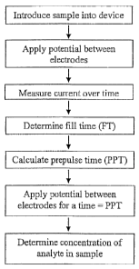
FIG. 1 illustrates a flow chart of an exemplary method of a method of
determining
the concentration of an analyte in a sample in accordance with the present
invention;
FIG. 2A illustrates a side elevation schematic drawing (not to scale) of an
exemplary
embodiment of an electrochemical cell in accordance with the present
invention;
FIG. 2B illustrates a plan view, from above, of the electrochemical cell of
FIG. 2A;
FIG. 3 illustrates a schematic drawing (not to scale), in cross-section, of an
exemplary embodiment of a hollow electrochemical cell in accordance with the
present
invention;
FIG. 4 A illustrates a perspective view of an assembled test in accordance
with the
present invention;
FIG. 4B illustrates an exploded perspective view of an unassembled test strip
in
accordance with the present invention;
FIG. 4C illustrates an expanded perspective view of a proximal portion of the
test
strip in accordance with the present invention;
FIG. 5A illustrates a bottom plan view of one embodiment of a test strip
disclosed
herein;
FIG. 5B illustrates a side plan view of the test strip of FIG. 5A;
FIG. 5C illustrates a top plan view of the test strip of FIG. 5B;
FIG. 5D is a partial side view of a proximal portion of the test strip of FIG.
5C;
FIG. 6 illustrates an exploded view of an exemplary embodiment of an
immunosensor in accordance with the present invention, wherein the
immunosensor is
configured for use with a control unit having an electrochemical detection
system for
calculating a fill time;
CA 02826512 2013-09-06
- 11 -
FIG. 7 illustrates a plot of a current versus time transient performed using
an
exemplary embodiment of an electrochemical cell in conjunction with an
exemplary
embodiment for testing a variety of blood samples provided herein;
FIG. 8 illustrates a plot of a current versus time transient performed using
another
exemplary embodiment of an electrochemical cell in conjunction with an
exemplary
embodiment for testing a variety of blood samples provided herein;
FIG. 9 illustrates a plot of the results of testing a variety of blood samples
using a
variable prepulse time method according to an exemplary embodiment and a fixed
time
method;
FIG. 10 illustrates a plot of fill time versus haematocrit level for a variety
of blood
samples provided herein;
FIG. 11 illustrates a test voltage waveform in which the test meter applies a
plurality
of test voltages for prescribed time intervals;
FIG. 12 illustrates a plot of the results of testing a variety of blood
samples without
correcting for fill time;
FIG. 13A illustrates the same data as FIG. 12 plotted against the hematocrit
of the
samples;
FIG 13B illustrates a plot of the data shown in FIG. 12 corrected for fill
time and
plotted against the hematocrit of the sample;
FIG. 14 illustrates a plot of the results of testing a variety of blood
samples in a
clinical setting;
FIG. 15 illustrates a plot of current versus time transients obtained when
blood with
hematocrits in the range of 15% to 72% was loaded into another exemplary
embodiment of
an electrochemical sensor in conjunction with an exemplary embodiment for
testing a
variety of samples provided herein.
FIG. 16 illustrates an alternate plot of the data shown in FIG. 15.
DETAILED DESCRIPTION
The following detailed description should be read with reference to the
drawings, in
which like elements in different drawings are identically numbered. The
drawings, which
are not necessarily to scale, depict selected embodiments and are not intended
to limit the
CA 02826512 2015-07-22
-12-
scope of the invention. The detailed description illustrates by way of
example, not by way of
limitation, the principles of the invention.
As used herein, the terms "about" or "approximately" for any numerical values
or
ranges indicate a suitable dimensional tolerance that allows the part or
collection of
components to function for its intended purpose as described herein. In
addition, as used
herein, the terms "patient," "host," "user," and "subject" refer to any human
or animal
subject and are not intended to limit the systems or methods to human use,
although use of
the subject invention in a human patient represents a preferred embodiment.
Certain exemplary embodiments will now be described to provide an overall
understanding of the principles of the structure, function, manufacture, and
use of the
devices and methods disclosed herein. One or more examples of these
embodiments are
illustrated in the accompanying drawings. Those skilled in the art will
understand that the
devices and methods specifically described herein and illustrated in the
accompanying
drawings are exemplary embodiments. The features illustrated or described in
connection
with one exemplary embodiment may be combined with the features of other
embodiments.
The presently disclosed systems and methods are suitable for use in the
determination of a wide variety of analytes in a wide variety of samples, and
are particularly
suited for use in the determination of analytes in whole blood, plasma, serum,
interstitial
fluid, or derivatives thereof. In an exemplary embodiment, a glucose test
system based on a
thin-layer cell design with opposing electrodes and tri-pulse electrochemical
detection that is
fast (e.g., about 5 second or less analysis time), requires a small sample
(e.g., about 0.4 pt
or less), and can provide improved reliability and accuracy of blood glucose
measurements.
In the reaction cell to assay analyte, glucose in the sample can be oxidized
to gluconolactone
using glucose dehydrogenase and an electrochemically active mediator can be
used to
shuttle electrons from the enzyme to a palladium working electrode. More
particularly, a
reagent layer coating at least one of the electrodes in the reaction cell can
include glucose
dehydrogenase (GDH) based on pyrroloquinoline quinone (PQQ) co-factor and
ferricyanide.
In another embodiment, the enzyme GDH based on the PQQ co-factor
DOCSTOR 5249334\1
CA 02826512 2013-09-06
- 13 -
may be replaced with the enzyme GDH based on the Ravin adenine dinucleotide
(FAD) co-
factor. When blood or control solution is dosed into the reaction chamber,
glucose is
oxidized by GDH(ox) and in the process converts GDH(ox) to GDH(red), as shown
in the
chemical transformation T.1 below. Note that GDH(ox) refers to the oxidized
state of
GDH, and GDH (red) refers to the reduced state of GDH.
T.1 D-Glucose + GDH(ox) --> Gluconic acid + GDH(red)
A potentiostat can be utilized to apply a tri-pulse potential waveform to the
working
and counter electrodes, resulting in test current transients used to calculate
the glucose
concentration. Further, additional information gained from the test current
transients may
be used to discriminate between sample matrices and correct for variability in
blood
samples due to hematocrit, temperature variation, electrochemically active
components, and
identify possible system errors.
The subject methods can be used, in principle, with any type of
electrochemical cell
having spaced apart first and second electrodes and a reagent layer. For
example, an
electrochemical cell can be in the form of a test strip. In one aspect, the
test strip may
include two opposing electrodes separated by a thin spacer for defining a
sample-receiving
chamber or zone in which a reagent layer is located. Applicants note that
other types of test
strips, including, for example, test strips with co-planar electrodes may also
be used with the
methods described herein.
The methods for determining a concentration of an analyte in a sample
disclosed
herein can be used with any sample analyzing device and/or system. The devices
typically
include at least one working electrode and one counter electrode between which
an electric
potential can be applied. The sample analyzing device can generally be
associated with a
component for applying the electric potential between the electrodes, such as
a meter.
Applicants note that a variety of test meters can be used with the systems and
methods
described herein. However, in one embodiment, the test meter includes at least
a processor,
which may include one or more control units configured for performing
calculations
capable of calculating a correction factor in view of at least one measured or
calculated
parameter as well as configured for data sorting and/or storage. The
microprocessor can be
CA 02826512 2013-09-06
- 14 -
in the form of a mixed signal microprocessor (MSP) such as, for example, the
Texas
Instruments MSP 430. The TI-MSP 430 can be configured to also perform a
portion of the
potentiostat function and the current measurement function. In addition, the
MSP 430 can
also include volatile and non-volatile memory. In another embodiment, many of
the
electronic components can be integrated with the microcontroller in the form
of an
application specific integrated circuit.
The sample analyzing device can also be associated with one or more components
that are capable of measuring a fill time of a sample when it is introduced to
the device.
Such components can also be capable of calculating a concentration of an
analyte in the
sample in view of the fill time. Such components are generally referred to
herein as control
units. Further, the terms analyte, antigen, and antibodies are used
interchangeably within,
and thus, use of one term is equally applicable to all three terms, unless
otherwise indicated
or reasonably known by one skilled in the art.
In one exemplary embodiment of a method for determining a concentration of an
analyte in a sample, a sample is introduced into an electrochemical cell of a
sample
analyzing device that has a working electrode and a counter electrode. An
electric potential
can be applied between the working and counter electrodes of the
electrochemical cell and a
fill time of the sample into, for example, a capillary space of the
electrochemical cell, can be
determined. A prepulse time can be calculated in view of at least the fill
time of the sample
and an electric potential can be applied between the working electrode and the
counter
electrode for a length of time equal to the prepulse time. A concentration of
the analyte in
the sample can then be determined. By calculating the prepulse time in view of
the fill time,
more accurate results can be achieved for analyte concentration. For example,
errors, such
as those that can result from varying haematocrit levels across samples, can
be accounted
for, thereby leading to more accurate determinations of the concentrations of
the analytes in
the samples. Methods can also account for the effects of temperature, as
discussed in
greater detail below. In an alternative embodiment for detecting a
concentration of an
analyte in a sample, errors are corrected for based on a determined initial
fill velocity rather
than a determined fill time. One example of such a method is disclosed in U.S.
Patent
Application Serial No. 12/649,509 entitled "Systems, Devices and Methods for
Measuring
Whole Blood Haematocrit Based on Initial Fill Velocity," of Ronald C.
Chatelier, Dennis
CA 02826512 2013-09-06
Rylatt, Linda Raineri, and Alastair M. Hodges, filed on December 30, 2009 and
published
as U.S. Publication No. 2011/0155584.
In an alternative embodiment, an estimate of a level of haematocrit level can
be
determined. In some embodiments, the estimate of a level of haematocrit can be
determined
5 without reference to an associated analyte concentration. As a result,
assessments related to
conditions such as anemia can be made. In such a system, only a level of
haematocrit is
measured without making other concentration determinations. Determining a
level of
haematocrit based on the disclosed teachings can allow determinations to be
made quickly
and accurately, often in less than a second. For example, haematocrit levels
of a drop of
10 blood can be determined in less than a second merely by dropping the
blood onto a sensor
strip of a sample analyzing device. Once the blood is disposed on the strip, a
digital readout
of the haematocrit level can be provided almost instantaneously.
A fill time can be used in a variety of ways to improve a determination of a
concentration of an analyte. For example, the fill time of the sample can be
used to
15 calculate a prepulse time. By adjusting the prepulse time in view of the
fill time, longer
reaction times can be provided for samples which take a longer time to fill
the sensor. For
example, if the sample includes whole blood, then haematocrit level can be a
factor in the
fill time of the sample. Adjusting the prepulse time in view of the fill time
can thus allow
for more accurate concentrations to be determined over a range of haematocrit
levels. In
some embodiments, the haematocrit level can be linked to the fill time, e.g.,
an estimate of
the haematocrit level can be determined in view of the fill time. In such an
instance, the
haematocrit levels can be accounted for in the determination of the analyte
concentration in
order to provide more accurate analyte concentration determinations.
In one exemplary embodiment, the steps illustrated in FIG. 1 can be used to
determine the concentration of an analyte in a sample. As shown, a sample is
first
introduced into the device. Any type of sample analyzing devices can be used
in
conjunction with at least some of the systems and methods disclosed herein.
These devices
can include, by way of non-limiting example, electrochemical cells,
electrochemical
sensors, glucose sensors, glucose meters, hemoglobin sensors, antioxidant
sensors,
biosensors, and immunosensors. One exemplary embodiment of a sample analyzing
device
is an electrochemical sensor. The electrochemical sensor can include at least
two
CA 02826512 2013-09-06
16
electrodes. The at least two electrodes can be configured in any way, for
example, the
electrodes can be on the same plane or on different planes. A sample can be
introduced into
the electrochemical cell.
In one embodiment, the introduction of a sample may be detected by an
automatic
technique in which the meter monitors a change in voltage, current, or
capacitance, a change
which indicates that sample has been dosed into the sample reaction chamber.
Alternatively, the physiological sample may be detected by a manual technique
in which the
user visually observes the filling of the sample reaction chamber and
initiates the test by
pressing a button. In another embodiment, an optical detector in the meter can
sense the
dosing of the sample. The time taken by the sample to fill the reaction
chamber can
likewise be measured by any number of similar techniques. In one embodiment,
the
electrodes can be configured such that when a sample is introduced into the
sensor, the
second electrode is contacted prior to or simultaneous with the first
electrode as the sample
fills the sensor. However, as the sample fills the sensor, the first electrode
is limiting in the
current it can sustain relative to the voltage applied to the second
electrode. The first
electrode can therefore limit the current flowing in the electrochemical
sensor. Prior to,
simultaneous with, or immediately after the sample contacts the first
electrode, a potential
can be applied between the electrodes such that when the first and second
electrodes are
bridged by the sample liquid a current flows between them. In one embodiment
of the
methods disclosed herein, the current versus time response during the sensor
filling can be
used to determine the point at which the sensor is adequately filled. For
example, adequate
filling can mean that sufficient liquid has filled the sensor to entirely
cover at least the first
electrode. In some embodiments, the current versus time response can be a
discontinuity in
the rate of change of current with time, such as an increased drop in current
or a decreased
rate of increase. One example of the above methods is disclosed in U.S. Patent
Application
Serial No. 12/885,830 of Kranendonk et al., entitled "Apparatus and Method for
Improved
Measurements of a Monitoring Device," filed on September 20, 2010 and
published as U.S.
Publication No. 2012/0067741.
In one embodiment of the methods disclosed herein, a potential of between
about
+10 mV to about +30 mV can be applied between the first and second electrodes
of an
electrochemical cell for a period of time, e.g., about 1000 ms, as a sample
introduced into
CA 02826512 2013-09-06
- 17 -
the device fills the cell. In one exemplary embodiment, a potential of about
+20 mV can be
applied between the first and second electrodes as a sample introduced into
the device fills
the cell. The current flowing between the electrodes can be measured at
predetermined
intervals during this time. For example, the current can be measured every 2
milliseconds
("ms") and the average current can be stored every 10 ms. The c-urrent data
can then be
analyzed, by a control unit, for example. In some embodiments, the control
unit can include
a microprocessor. The analysis of the current data measured over the
approximately 1000
ms, during which the sample fills the device, can include a determination of
the latest time
at which the current decreases by a predetermined amount. This time can be
used as the fill
time (1-q) of the sample. For example, in one embodiment, the latest time at
which the
current decreases by more than 0.4 micro-Ampere ("}i.A") over a 40 ms interval
can be used
to determine the time at which the sample has filled the cell.
In some embodiments, the step of determining current drop time can include
calculating a difference between in at least two current values where the
difference is
greater than or less than a predetermined threshold value. Various
predetermined threshold
values can be employed. For example, when the area of the working electrode is
about 4.2
square millimetres and hematocrits as high as about 75% are being assayed, the
= predetermined threshold value can be in the range of about 0.4
micramperes over about a 40
ms time period. In other exemplary embodiment, when the area of the working
electrode is
about 4.2 square millimetres and hematocrits as high as about 60% are being
assayed, the
predetermined threshold value can be in the range of about 0.7 microamperes to
about 0.9
micramperes over about a 50 ms time period. In some embodiments, the step of
determining current drop time can include calculating an inflection point in
the measured
current as a function of time.
In some embodiments, detecting the presence of a sample can include applying
an
electric potential between the two electrodes, and measuring a change in
current values that
is greater than or less than a predetermined threshold value. Various
predetermined
threshold values can be employed. For example, when the area of the working
electrode is
about 4.2 square millimeters, the predetermined threshold value can be in the
range of about
3 microamperes. In other embodiments, detecting the presence of a sample can
include
applying a generally constant current between the two electrodes, and
measuring a change
CA 02826512 2013-09-06
- 18 -
in an electric potential that is greater than or less than a predetermined
threshold. For
example, the predetermined threshold value can be in the range of about 200
mV. In other
exemplary embodiment, the threshold value can be about 400 mV.
After the sample has filled the cell, a first electric potential, having a
first polarity,
can be applied between a first and second electrode and a resulting current
measured as a
function of time. This first electric potential can be referred to, for
example, as a prepulse.
In some embodiments, the length of time that a prepulse can be applied can be
about 5
seconds. In other embodiments, the fill time (FT) of the sample, which can be
determined
using any of the techniques discussed above, can be used to calculate the
length of time that
a prepulse can be applied. This time period can be referred to, for example,
as a prepulse
time (PPT). For example, the calculation of prepulse time can allow for longer
prepulse
times for samples that take longer to fill the sensor. In one embodiment, the
prepulse time
can be set according to the following exemplary parameters. For example, the
prepulse
time can be calculated as:
PPT (ms) = 3000 + (FT ¨ 300) x 9.3
For purposes of this calculation, for fill times less than 300 ms, the fill
time can be
set to 300 ms. This calculation allows the prepulse time (PPT) to be adjusted
to allow for
longer reaction times for samples that take more than a predetermined amount
of time, e.g.,
about 300 ms, to fill the sensor. For purposes of simplifying calculation and
to place
boundaries on the total test time a maximum prepulse time can be set if the
fill time is
longer than a predetermined length of time. For example, in one embodiment, if
the fill
time is greater than about 500 ms, e.g., about 515 ms, the prepulse time (PPT)
can be set
equal to 5000 ms. Thus, in this exemplary embodiment, the minimum PPT (for
fill times
less than about 300 ms) is 3000 ms and the maximum PPT (for fill times greater
than about
500 ms, e.g., about 515 ms) is about 5000 ms. In other embodiments, the
calculation of
prepulse time can be adjusted so as to take into account other properties and
requirements of
a particular sample or analyte. For example, the variables and constants in
the equation
shown above for calculation of prepulse time can be adjusted so as to provide
alternate
maximum and minimum prepulse times, or combinations thereof.
CA 02826512 2013-09-06
- 19 -
Once the prepulse time has been determined, a potential can be applied between
the
electrodes of the cell for a time equal to the prepulse time (PPT) and a
resulting current
measured as a function of time. At least a portion of the data (current as a
function of time)
provides a first time-current transient. The first electrical potential can be
sufficiently
negative with respect to the second electrode such that second electrode
functions as the
working electrode in which a limiting oxidation current is measured. After the
first time
interval has elapsed, a second electric potential can be applied between the
first and second
electrodes for a second time interval. The second electrical potential causes
a current that is
measured as a function of time to produce a second time-current transient. In
one
embodiment, the second potential has a second polarity, which is opposite to
the first
polarity. For example, the second potential can be sufficiently positive with
respect to
second electrode such that first electrode functions as the working electrode
in which a
limiting oxidation current is measured. In one exemplary embodiment, the first
electric
potential and second electrical potential can range from about ¨0.6 V to about
+0.6 V. The
time interval of the time-current transients can, in one embodiment, can be in
the range of
about 1 second to 10 seconds, and preferably in the range of about 1 to 5
seconds. In
another embodiment, a sum of the first time interval and the second time
interval is less than
about 5 seconds. It should also be noted that the first time interval does not
have to be the
same as the second time interval. In one embodiment, the second electric
potential is
applied immediately following the application of the first electric potential.
In an
alternative embodiment, a delay or open circuit potential is introduced in
between the first
electric potential and the second electric potential. In another alternative
embodiment, a
delay is introduced after physiological sample is detected in the sample
reaction chamber,
but before the application of the first electric potential. The delay can be
in the range of
about 0.01 and about 3 seconds, preferably from about 0.05 to about 1 second
and most
preferably from about 0.5 to about 0.9 seconds.
In one exemplary embodiment, a first test potential El can be applied between
the
electrodes for a first test potential time T1, e.g., PPT milliseconds. For
example, a potential
of +300 mV can be applied. After the first test potential time T1, e.g., PPT
milliseconds,
has elapsed, a second test potential E2 can be applied between the electrodes
for a second
test potential time interval T2, e.g., -300 mV for 1000 ms. During T1 and T2,
the cell current
CA 02826512 2013-09-06
=
- 20 -
as a function of time can be measured, herein called a time current transient
or a current
transient and referred to as ia(t), during first test potential time interval
T1, and as ib(t) during
the second test potential time interval T2. For example, the current as a
function of time can
be measured every 10 ms with the average current stored every 50 ms. At least
a portion of
the data from the first and second potentials (current as a function of time)
can provide first
and second time-current transients. The concentration of an analyte in the
sample can then
be determined from the current data using any number of algorithms.
Examples of algorithms for determining analyte concentration can be found at
least
in U.S. Patent Application Serial No. 11/278,341 of Chatelier et al., entitled
"Methods And
Apparatus For Analyzing A Sample In The Presence Of Interferents," filed on
March 31,
2006 and granted as U.S. Patent No. 8,163,162. In one exemplary embodiment,
the current
data can be analyzed using a "calibration-free, corner-corrected algorithm"
similar to those
disclosed in the aforementioned patent application. In one embodiment, an
analyte
concentration can be calculated using the algorithm as shown in Equation (Eq.)
I.
Eq. 1 a = (6; Y ) (4,12 -zgr}
Zgr)
In Eq. 1, G is the analyte concentration, the terms j1, ir, and i2 are current
values and
the terms p, zgr, and a are empirically derived calibration constants.
In one embodiment of the invention, p may range from about 0.2 to about 4, and
preferably from about 0.1 to about 1. The calibration factor a can be used to
account for
possible variations in the dimensions of the electrochemical cell. Variations
in the
dimensions of the electrochemical cell can cause a proportional shift in the
magnitude of the
measured current. Under certain circumstances, manufacturing processes can
cause the
electrode area to vary from one lot of test strips to another lot of test
strips. Calculating a
calibration factor a for each lot of test strips helps to compensate for
variations in electrode
area and the height of the cell. The term a can be calculated during the
calibration process
of a test strip lot.
A calibration factor zgr is used to account for variations in the background.
A
presence of an oxidizable species within the reagent layer of the cell before
the addition of a
sample may contribute to a background signal. For example, if the reagent
layer were to
CA 02826512 2013-09-06
-21 -
contain a small amount of ferrocyanide (e.g., reduced mediator) before the
sample was
added to the test strip, then there would be an increase in the measured test
current which
would not be ascribed to the analyte concentration. Because this would cause a
constant
bias in the overall measured test current for a particular lot of test strips,
this bias can be
corrected for using the calibration factor Z. Similar to the terms p and a, Z
can also be
calculated during the calibration process. Exemplary methods for calibrating
strip lots are
described in U.S. Patent No. 6,780,645.
In one exemplary embodiment, p can be 0.51, a can be 0.2, and zgr can be 5.
While
the method disclosed herein is described with the use of calibration factors,
p, a, and zgr,
one skilled in the art will appreciate that their use is not required. For
example, in one
embodiment, glucose concentration could be calculated without p, a, ancUor Z
(in Eq. 1 p
and/or a could be set equal to one and zgr could be set equal to zero). A
derivation of Eq. 1
can be found in a pending U.S. Application No. 11/240,797 which was filed on
September
30, 2005 and entitled "Method and Apparatus for Rapid Electrochemical
Analysis," and
granted as U.S. Patent No. 7,749,371.
Current value ir can be calculated from the second. current transient and
current
value i1 can be calculated from the first current transient. All current
values (e.g. r, it, and
i2) stated in Eq. 1 and in subsequent equations can use the absolute value of
the current.
Current values ir, j1, can be, in some embodiments, an integral of current
values over a time
interval of a current transient, a summation of current values over a time
interval of a
current transient, or an average or single current value of a current
transient multiplied by a
time interval of the current transient. For the summation of current values, a
range of
consecutive current measurement can be summed together from only two current
values or
to all of the current values. Current value i2 can be calculated as discussed
below.
For example, where the first time interval is 5 seconds long, i1 may be the
average
current from 1.4 to 4 seconds of a 5 second long period and ir may be the
average current
from 4.4 to 5 seconds of a 5 second long period, as shown in Eq. 2a and 3a,
below.
________________________________________ 4 4=1
t
CA 02826512 2013-09-06
- 22 -
Eq. 2a
4
Eq. 3a
t-1.4
In another example, where the first interval is 5 seconds long it may be the
sum of
currents from 3.9 to 4 seconds of a 5 second long period and ir may be the sum
of currents
from 4.25 to 5 seconds of a 5 second long period, as shown in Eq. 2b and 3b,
below.
5
= i(t)
Eq. 2b 1=4.25
4
= E i(t)
Eq. 3b =3.9
A magnitude of current for the first current transient can be described as a
function
of time by Eq. 4.
ia(t)= iõ 1+ 2E exp(-47r2n2Dt
Eq. 4 n=1 L2
The term iõ is the steady-state current following the application of first
test potential
El, D is the diffusion coefficient of the mediator, L is the thickness of the
spacer. It should
be noted that in Eq. 4, t refers to the time elapsed after first test
potential El was applied. A
magnitude of current for the second current transient can be described as a
function of time
by Eq. 5.
(--
Eq. 5 ib (t) = iõ 1+ 41 exp47r2n2Dtj}
L2
n=1
CA 02826512 2013-09-06
- 23 -
There is a factor of two difference for the exponential term in Eq. 5 as
compared to
the exponential term in Eq. 4 because the second current transient is
generated from the
second test potential E2, which was opposite in polarity to the first test
potential E1, and was
applied immediately after the first test potential El. It should be noted that
in Eq. 5, t refers
to the time elapsed after second test potential E2 was applied.
A peak current for first test potential time interval T1 can be denoted as ipa
and a
peak current for second test potential time interval T2 can be denoted as ipb.
If both first
peak current ipa and second peak current ipb were measured at the same short
time after the
application of first test potential Eland second test potential E2
respectively, for example 0.1
seconds, Eq. 4 can be subtracted from Eq. 5 to yield Eq. 6.
Eq. 6 1pb 2ipa = ss
Because it has been determined that ipa is controlled mainly by interferents,
ipb can
be used with ip, together to determine a correction factor. For example, as
shown below i,ó
can be used with ipa in a mathematical function to determine a corrected
current which is
proportional to glucose and less sensitive to interferents.
Eq. 7 was derived to calculate a current i4 which is proportional to glucose
and has a
relative fraction of current removed that is ascribed to interferents.
i = i ¨2ipa + i
2 õ
pbss
Eq. 7
The term iõ was added to both the numerator and denominator to allow the
numerator to approach zero when no glucose is present. The term iõ may be
estimated
using Equation 8A, for currents at times greater than a minimum time, where a
suitable
minimum time can be estimated from Equation 8B.
( 47r2Dt
Eq. 8A i(t) = iõ 1 + 4 expi
L2
CA 02826512 2013-09-06
- 24 -
t = ¨ L2ln 0.01
Eq. 8B
12rc2D
in which, iõ is the steady-state current following application of the second
electric
potential; i is the measured current which is a function of time; D is the
diffusion coefficient
of the redox-active molecule, where this coefficient may be determined from
Fick's first
law, i.e. J(x,t)=-.D dC(x,t) /dx; L is the spacer thiclaiess; and t is the
time for the application
of the second electric potential where t=0 for the beginning of the second
time interval.
In one exemplary embodiment, the current value, i2, can be calculated
according to
Eq. 9.
Eq. 9
i2 ir
,33
Thus, Eq. I can enable accurate measurements of analyte concentration in the
presence of interferents.
As discussed above, an estimate of a level of haematocrit can be determined
without
reference to an associated analyte concentration. For example, haematocrit
levels of a drop
of blood can be determined from current values and. an analyte concentration.
In one
exemplary embodiments, an estimate of the haematocrit (H) can be derived from
Eq. 10.
Eq. 10 II = -162.5 log(i) + 119.1 log(G) + 235.4
In some embodiments, the value of the analyte concentration (G) can be
corrected in
view of the haematocrit level, e.g., using Eq. 11A and 11B.
Eq. 11A G' = G + Corr for G < 100 mg/dL
Eq. 11B = G (1 + Corr/100) for G 100 mg/dL
CA 02826512 2013-09-06
- 25 -
In Eq. 11A and 11B, the correction factor Corr can be calculated using sine
functions whose amplitude varies with H. For example, at values of H<30% the
following
equations can be used to calculate Corr.
Eq. 12A Corr = -0.4 (30-H) sin(nG/400) for G<400
mg/dL
Eq. 12B Corr = 0 for G_>_400 mg/dL
= 10 where the range of Corr is restricted to 0 to -5. .
When H>50%, an "asymmetric sine function" can be used where the amplitudes of
the positive and negative lobes are different. However, the function is
continuous so that
there is no sudden step in the correction. For example, Eq. 13A to 13C can be
used to
calculate Corr for H>50%.
Eq. 13A Corr = -0.2 (H-50) sin(nG/180) for G<180
mg/dL
Eq. 13B Corr = -0.5 (H-50) sin(nG/180) for
180.5_270 mg/dL
Eq. 13C Corr = +0.5 (H-50) for G>270 mg/dL
where the range of Corr is restricted to 0 to -5 for G<180, and 0 to 5 for
G?_180.
In another embodiment, the value of the analyte concentration (G) can be
corrected
in view of the fill time without deriving an estimate of the haematocrit (H),
e.g., using Eq.
14A (when G < 100 mg/dL) and 14B (when G 100 mg/dL) in conjunction with Eqs.
15A,
15B, and 15C.
Eq. 14A G' = G + Corr for G < 100 mg/dL
CA 02826512 2013-09-06
- 26 -
Eq. 14B G' = G (1 + Corr/100) for G 100 mg/dL
The correction factor Corr in Eq. 14A and 14B can be calculated in view of the
fill
time (FT) based on a series of threshold values of FT. For example, the
following equations
can be used to calculate Corr using two threshold values of FT, Thi and Th2.
Eq. 15A if Thi < FT < Th2 then Corr = 50(FT- Thi)
Eq. 15B if FT < Thi then Corr = 0
Eq. 15C if FT > Th2 then Corr = 10
In an exemplary embodiment, the threshold value Thi can be about 0.2 seconds
and
the threshold value Th2 can be about 0.4 seconds. For example, when blood
fills the sensor
in less than about 0.2 seconds, then its fill behavior can be described as
close to ideal. Fill
times of less than about 0.2 seconds usually occur when the hematocrit is low
enough that
that the viscosity of the sample has a minimal effect on the fill behavior of
the sample. As a
consequence of the low hematocrit, most of the glucose is believe to be
partitioned into the
plasma phase where it can be oxidized rapidly. Under these conditions, there
is little need
to correct the glucose result for the effect of fill time, and so the
correction factor can be set
to zero. Alternatively, when the hematocrit in the sample is high, the
viscosity of the sample
can affect the fill time of the sample. As a results, the sample can take more
than about 0.4
seconds to fill the sensor. As a consequence of the high hematocrit, most of
the glucose is
believe to be partitioned into the red blood cells and so a lower fraction of
the glucose is
oxidized. Under these conditions, the glucose result can be corrected in view
of the fill
time. However, it can be important not to over-correct the glucose value, and
so, in an
exemplary embodiment, the correction factor can be restricted to a maximum of
about 10
mg/dL plasma glucose or about 10% of the signal. An empirically-derived linear
equation
can be used to gradually increase the correction term in the range of about 0
to about 10 as
the fill time increases in the range of about 0.2 to about 0.4 seconds.
CA 02826512 2013-09-06
- 27 -
One exemplary embodiment of a device that can be used in conjunction with at
least
some of the systems and methods disclosed herein is a glucose sensor. The
glucose sensor
can include an electrochemical cell, such as the cell illustrated in FIGS. 2A
and 2B. The
cell can include a thin strip membrane 201 having upper and lower surfaces
202, 203, and
can also include a cell zone 204 defined between a working electrode 206
disposed on the
lower surface 203 and a counter/reference electrode 205 disposed on the upper
surface 202.
The membrane thickness can be selected to achieve a desired result, such as
having the
reaction products from a counter electrode arrive at a working electrode. For
instance, the
membrane thickness can be selected so that the electrodes are separated by a
distance t,
which can be sufficiently close such that the products of electrochemical
reaction at the
counter electrode can migrate to the working electrode during the time of the
test and a
steady state diffusion profile can be substantially achieved. Typically t can
be less than
approximately 500 micrometers, alternatively in the range of about 10
micrometers to about
400 micrometers, and more particularly in the range of about 80 micrometers to
about 200
micrometers. In one embodiment a spacing between the electrodes can be
selected such that
the reaction products from a counter electrode arrive at a working electrode
before the end
of the assay.
The electrodes can also have a variety of configurations. For instance, the
electrodes
can be planar. Further, while in the illustrated embodiment the electrodes
205, 206 are
facing each other and are substantially opposed, in other embodiments the
electrodes can
just be facing each other, they can be substantially opposed to each other, or
they can have a
side-by-side configuration in which the electrodes are positioned
approximately in the same
plane. Examples of different electrode configurations can be found at least in
U.S. Patent
No. 7,431,820 of Hodges, entitled "Electrochemical Cell," and filed on October
14, 2003.
A sample deposition or "target" area 207 can be defined on the upper surface
202 of
the membrane 201 and can be spaced at a distance greater than the membrane
thickness
from the cell zone 204. The membrane 201 can have a diffusion zone 208 that
can extend
between the target area 207 and the cell zone 204. A suitable reagent can
include a redox
mediator M, an enzyme E, and a pH buffer B, each of which can be contained
within the cell
zone 204 of the membrane and/or between the cell zone 204 and the target area
207. The
CA 02826512 2013-09-06
- 28= -
reagent can also include stabilizers and the like. In use of the sensor, a
drop of blood can be
= placed on the target zone 207, and the blood components can wick towards
the cell zone
204.
Each of electrodes 205, 206 can have a predefined area. In the embodiments of
FIGS. 2A and 2B the cell zone 204 can defined by edges 209, 21.0, 211 of the
membrane,
which can correspond with edges of the electrodes 205, 206 and by leading
(with respect to
the target area 207) edges 212, 213 of the electrodes. In the present example
the electrodes
can be about 600 angstrom thick and can be from about 1 to about 5 mm wide
although a
variety of other dimensions and parameters can be used without departing from
the scope of
= the present invention.
Alternatively, both sides of the membrane can be covered with the exception of
the
target area 207 by laminating layers 214 (omitted from plan views) which can
serve to
prevent evaporation of water from the sample and to provide mechanical
robustness to the
apparatus. Evaporation of water is believed to be undesirable as it
concentrates the sample,
allows the electrodes to dry out, and allows the solution to cool, affecting
the diffusion
coefficient and slowing the enzyme kinetics, although diffusion coefficient
can be estimated
as above.
In an alternative embodiment, illustrated in FIG. 3, a hollow electrochemical
cell for
use with the systems and methods disclosed herein is provided. The electrodes
305, 306 can
= be supported by spaced apart polymer walls 330 to define a hollow cell.
An opening 331
can be provided on one side of the cell whereby a sample can be admitted into
the cavity
332. In this embodiment a membrane is not used, although in some embodiments a
membrane can be included. The electrodes can have a variety of configurations,
at least as
discussed above. By way of non-limiting example, the electrodes can be spaced
apart by
less than about 500 micrometers, preferably in the range of about 10 or about
20
micrometers to about 400 micrometers, and more preferably in a range of about
80
micrometers to about 200 micrometers. The effective cell volume can be about
1.5
microliters or less.
The electrochemical cells of FIGS. 2A, 2B, and 3 can be used in conjunction
with
the meters, control units, and other components and steps of the devices,
systems, and
methods disclosed herein. Further disclosures related to the electrochemical
cells of FIGS.
CA 02826512 2013-09-06
- 29 -
2A, 2B, and 3 are found in U.S. Patent No. 6,284,125 of Hodges et al.,
entitled
"Electrochemical cell" and filed on April 17, 1998.
For example, electrochemical cells used in
conjunction with the present disclosures can have two electrode pairs. The
electrode pairs
can include any combination of working, counter, counter/reference, and
separate reference
electrodes.
Another exemplary embodiment of a device that can be used in conjunction with
at
least some of the systems and methods disclosed herein is the sensor described
below and
illustrated in FIGS. 4A through 5D. The sensor can be in the form of a form of
a test strip
62 including an elongate body 59 that extends along a longitudinal axis L from
a proximal
end 80 to a distal end 82 and having lateral edges 56, 58. Body 59 can include
a proximal
sample reaction chamber 61 that contains electrodes 164, 166 and a reagent 72.
Test strip
body 59 can further include distally positioned electrical contacts 63, 67 for
electrically
communicating with a test meter (not illustrated).
In one aspect, test strip 62 is formed from multiple layers including a first
electrically conductive layer 66, a spacer 60, a second electrically
conductive layer 64. First
electrically conductive layer 66 and/or second electrically conductive layer
64 can be
formed from a variety a conductive materials that are, in one embodiment,
positioned on an
insulating sheet (not shown). Spacer layer 60 can be formed from a variety of
electrically
insulating materials and can include, or be formed from, an adhesive. One
skilled in the art
will appreciate that while a three layer test strip is illustrated, additional
electrically
conductive or insulative layers could be used to form test strip body 59.
As illustrated in FIGS. 4A through 4C, proximal sample reaction chamber 61 can
be
defined by first electrically conductive layer 66, second electrically
conductive layer 64, and
spacer layer 60. As discussed in more detail below, reaction chamber 61 can
also include a
reagent 72 and first and second electrodes 166, 164. For example, a cutout
area 68 in spacer
60 can expose a portion of second electrically conductive layer 64 and first
electrically
conductive layer 66, and thereby defines first electrode 166 and second
electrode 164,
respectively. Reagent 72 can be in the form of a layer positioned on first
electrode 166.
In one embodiment, reaction chamber 61 is adapted for analyzing small volume
samples. For example, sample reaction chamber 61 can have a volume ranging
from about
CA 02826512 2013-09-06
- 30 -
0.1. microliters to about 5 microliters, preferably about 0.2 to about 3
microliters, and more
preferably about 0.3 microliters to about 1 microliter. To accommodate a small
sample
volume, the electrodes are preferably closely spaced. For example, where
spacer 60 defines
the distance between first electrode 166 and second electrode 164, the height
of spacer 60
can be in the range of about 1 micron to about 500 microns, preferably in the
range of about
microns and about 400 microns, and more preferably in the range of about 40
microns
and about 200 microns.
To further assist with the reduction in the volume of reaction chamber 61 the
10 longitudinal and/or lateral dimension of cutout area 68 and/or body 59
can be adjusted. For
example, test strip body 59 can include cut-away portions 51, 52 such that the
lateral width
of reaction chamber 61 is smaller than the full width (widest width) of test
strip body 59.
Cut-away portions 51, 52 can also facilitate delivery of a sample to reaction
chamber 61.
For example, cut-away portion 51, 52 can have a shape corresponding to a
portion of a
finger of a user. When a user expresses a drop of blood with a finger stick,
the cut-away
portions 51, 52 can help the user align a sample positioned on his/her finger
with a sample
receiving port (e.g., openings 70) in the lateral edge 56, 58 of body 59. One
skilled in the
art will appreciate that while two cut-away portions are illustrated, test
strip body 59 could
include only a single cut-away portion or no cut-away portions.
As stated above, the proximal portion of test strip body 59 can include at
least one
sample delivery port for delivery of a sample to reaction chamber 61. For
example, cutout
area 68 can extend transversely to the lateral edges 56, 58 of test strip body
59 to provide
two openings 70 for the delivering of physiological fluid to sample reaction
chamber 61.
Where two openings 70 are present one can act as a sample receiving port for
delivery of a
fluid sample while the other can act as a vent. One skilled in the art will
appreciate that
sample can be delivered to sample reaction chamber 61 using alternative
structures
including sample receiving ports and/or vents positioned at different
locations in test strip
body 59, such as, for example, sample receiving ports and/or vents positioned
in first and/or
second electrically conductive layers 66, 64.
In one embodiment, test strip 62 is adapted to draw sample into reaction
chamber 61
via capillary action. For example, the dimensions and surface characteristics
of reaction
chamber 61 and openings 70 can be adapted to produce a capillary force when a
liquid
CA 02826512 2013-09-06
-31 -
sample (e.g., whole blood) is brought into contact with one of openings 70.
One skilled in
the art will appreciate that reaction chamber 61 can include additional
structures to assist
with/create capillary forces such as, for example, beads, a porous membrane,
6.nd/or other
fillers.
As mentioned above, a reagent, such as reagent 72, can be disposed within
reaction
chamber 61. The composition of reagent 72 can vary depending on the intended
analyte
and the expected form of the sample. In one aspect, reagent 72 includes at
least a mediator
and an enzyme and is deposited onto first electrode 166. Various mediators
and/or enzymes
are within the spirit and scope of the present disclosure. For example
suitable mediators
include ferricyanide, ferrocene, ferrocene derivatives, osmium bipyridyl
complexes,
ruthenium (III) hexamine, and quinone derivatives. Examples of suitable
enzymes include
glucose oxidase, glucose dehydrogenase (GDH) based on pyrroloquinoline quinone
(PQQ)
co-factor,GDH based on nicotinamide adenine dinucleotide co-factor, and
flavine-adenine
dinucleotide (FAD) based GDH (FAD-GDH) . One exemplary reagent formulation,
which
would be suitable for making reagent layer 72, is described in pending U.S.
application Ser.
No. 10/242,951, entitled, Method of Manufacturing a Sterilized and Calibrated
Biosensor-
Based Medical Device, published as U.S. Published Patent Application No.
2004/0120848.
Distal to the proximal sample chamber 61, body 59 can include connection
tracks
that electrically connect first and second electrodes 166, 164 with distal
electrical contacts
63, 67. In one aspect, first electrically conductive layer 66 includes a first
connection track
76 that electrically connects first electrode 166 with a first electrical
contact 67. Similarly,
second electrically conductive layer 64 can include a second connection track
78 that
connects the second electrode 164 with a second electrical contact 63 (FIG.
5A).
First and second electrically conductive layers can also define first and
second
electrical contacts 67, 63 that facilitate electrical contact of test strip 62
with a test meter. In
one embodiment, a portion of first electrically conductive layer 66 extends
distally from the
distal end of spacer layer 60 and second electrically conductive layer 64 to
define first
electrical contact 67. Second electrical contact can be defined by a U-shaped
notch 65 in
the first electrically conductive layer 66 which exposes a portion of second
electrically
CA 02826512 2013-09-06
- 32 -
conductive layer 64. Applicants note that test strip 62 can include a variety
of alternative
electrical contact configurations for electrically connecting to a test meter.
For example,
U.S. Pat. No. 6,379,513 discloses electrochemical cell connection structures.
The sensors of FIGS. 4A through 5D can be used in conjunction with the meters,
control units, and other components and steps of the devices, systems, and
methods
disclosed herein. Further disclosures related to the electrochemical cells of
FIGS. 4A
through 5D are found in U.S. Patent Application Serial No. 11/278,341 of
Chatelier et al.,
entitled "Methods And Apparatus For Analyzing A Sample In The Presence Of
Interferents," filed on March 31 and granted as U.S. Patent No. 8,163,162.
Another exemplary embodiment of a sample analyzing device for use in
conjunction
with at least some of the methods disclosed herein, an immunosensor 110, is
illustrated in
FIG. 6 and is described in U.S. Patent Application Serial No. 12/570,268 of
Chatelier et al.,
entitled "Adhesive Compositions for Use in an Immunosensor," filed on
September 30,
2009 and granted as U.S. Patent No. 8,221,994. A plurality of chambers can be
formed
within the immunosensor, including a fill chamber, by which a sample can be
introduced
into the immunosensor, a reaction chamber, by which a sample can be reacted
with one or
more desired materials, and a detection chamber, by which a concentration of a
particular
component of the sample can be determined. These chambers can be formed in at
least a
portion of a lower electrode, an upper electrode, and a separator of the
immunosensor. The
immunosensor can also include a vent hole to allow air to enter and escape the
immunosensor as desired, and first and second sealing components to
selectively seal first
and second sides of the vent hole. The first sealing component can also form a
wall of the
fill chamber.
As illustrated, the immunosensor 110 includes a lower electrode 112 having
two liquid reagents 130, 132 striped onto it. The lower electrode 112 can be
formed using
any number of techniques used to form electrodes, but in one embodiment a
polyethylene
tetraphthalate (PET) sheet that is filled with barium sulphate is sputter-
coated with gold.
Other non-limiting example of forming an electrode are disclosed in U.S.
Patent No.
CA 02826512 2013-09-06
- 33 -
6,521,110 of Hodges et al., entitled "Electrochemical Cell" and filed on
November 10,
2000..
Likewise, the liquid reagents 130, 132 can have a number of different
compositions.
In one embodiment the first liquid reagent 130 includes an antibody conjugated
to an
enzyme, such as GDH-PQQ, in a buffer that contains sucrose, as well as a
poloxamer, such
= as Pluronics 0 block copolymers, an anticoagulant, such as citraconate,
and calcium ions.
In one embodiment the second liquid reagent 132 includes a mixture of
ferricyanide,
glucose, and a second mediator, such as phenazine ethosulfate, in an acidic
buffer, such as a
dilute citraconic acid solution. The first and second liquid reagents 130, 132
can be dried
onto the lower electrode 112. A number of techniques can be used to dry the
reagents 130,
132, but in one embodiment, following the striping of the reagents 130, 132 on
the lower
electrode 112, one or more infrared dryers can be applied to the reagents 130,
132. One or
more air dryers can also be used, for example, subsequent to the infrared
dryers. References
to a first reagent and a first liquid reagent and a second reagent and a
second liquid reagent
herein are used interchangeably and are not necessarily an indication that the
reagents are in
their liquid or dried form at a given time for a particular embodiment.
Further, some of the
components associated with the first and second liquid reagents can be used
interchangeably
and/or in both the first and second liquid reagents as desired. By way of non-
limiting
example, an anticoagulant can be associated with either or both of the first
liquid reagent
130 and the second liquid reagent 132.
A line can be formed in the sputter-coated gold between the reagents 130, 132
such
that an edge of reagent 132 is very close to, or touches, the line. The line
can be applied
using laser ablation or with a sharp metal edge. In one exemplary embodiment
the line can
be applied before the reagents 130, 132 are striped on the electrode. The line
can be
designed to electrically insulate the section of the lower electrode 112 under
the detection
chamber from the section that will be under the reaction chamber. This can
provide a better
definition of an area of the working electrode during the electrochemical
assay.
The immunosensor 110 can also include an upper electrode 114 having one or
more
magnetic beads 134 containing surface-bound antigens thereon. The antigens can
be
configured to react with the antibody disposed on the lower electrode 112 and
the sarnple
within a reaction chamber 118, as described in further detail below.
Applicants note that the
CA 02826512 2013-09-06
- 34 -
components disposed on the lower electrode 112 and on the upper electrode 114
can be
interchangeable. Thus, the lower electrode 112 can include one or more
magnetic beads
134 and the upper electrode 114 can include two liquid reagents 130, 132
striped onto it.
Further, although in the illustrated embodiment the length of the electrode
112 forms the
length of the entire body of the immunosensor 110, in other embodiments the
electrode can
be only a portion of a layer of an inununosensor that serves as the lower or
upper electrode
or multiple electrodes can be disposed on a single layer of an immunosensor.
Further,
because voltage applied to the irnmunosensor can be flipped and/or alternated,
each of the
lower and upper electrodes can serve as the working electrode and the counter
or
counter/reference electrode at different stages. For ease of description
purposes, in the
present application the lower electrode is considered the working electrode
and the upper
electrode the counter or counter/reference electrode.
A separator 116 disposed between the lower and upper electrodes 112, 114 can
have
a variety of shapes and sizes, but it generally is configured to desirably
engage the lower
and upper electrodes 112, 114 to form the immunosensor 110. In one exemplary
embodiment, the separator 116 includes adhesive on both sides. The separator
116 can
further include a release liner on each side of the two sides of the separator
116. The
separator 116 can be cut in a manner that forms at least two cavities. A first
cavity can be
formed to serve as a reaction chamber 118 and a second cavity can be formed to
serve as a
detection chamber 120. In one embodiment, the separator 116 can be kiss-cut
such that the
reaction chamber 118 is aligned with the electrodes 112, 114 to allow an
antigen-antibody
reaction therein while the detection chamber 120 is aligned with the
electrodes 112, 114 to
allow for the electrochemical determination of ferrocyanide therein.
In one embodiment, the separator 116 can be placed on the lower electrode 112
in a
manner that allows the magnetic beads 134 of the upper electrode 114 and the
first reagent
130 of the lower electrode 112 to be at least partially disposed in the
reaction chamber 118
and the ferricyanide-glucose combination of the second reagent 132 of the
lower electrode
112 to be at least partially disposed in the detection chamber 120. It can be
advantageous to
include an anticoagulant in each of the first and second liquid reagents 130,
132 so that an
anticoagulant is associated with each of the reaction and detection chambers
118, 120. In
some embodiments the combination of one of the upper and lower electrodes 112,
114 and
CA 02826512 2013-09-06
-35 -
the separator 116 can be laminated together to form a bi-laminate, while in
other
embodiments the combination of each of the lower electrode 112, the upper
elect-ode 114,
and the separator 116 can be laminated together to form a tri-laminate.
Alternatively,
additional layers may also be added.
A fill chamber 122 can be formed by punching a hole into one of the lower and
upper electrodes 112, 114 and the separator 116. In the illustrated embodiment
the fill
chamber is formed by punching a hole in the lower electrode 112 and the
separator 116 such
that the hole in the lower electrode 112 overlaps the reaction chamber 118. As
shown, the
fill chamber 122 can be a distance apart from the detection chamber 120. Such
a
configuration allows a sample to enter the immunosensor 110 through the fill
chamber 122
and flow into the reaction chamber 118 to be reacted, for example with the
first liquid
reagent 130 that includes the antibody conjugated to an enzyme in a buffer on
the first
electrode 112 and the magnetic beads 134 striped on the upper electrode 114,
without
entering the detection chamber 120. Once the sample has been reacted, it can
then flow into
the detection chamber 120 for interaction with the second liquid reagent 132,
for example
the mixture of ferricyanide, glucose, and the second mediator in an acidic
buffer.
A vent 124 can be formed by mulching a hole through each of the two electrodes
112, 114 and the separator 116 such that the vent 124 extends through the
entirety of the
Um-nunosensor 110. The hole can be formed in a suitable manner, such as, for
example,
drilled or punched in a number of different locations, but in one exemplary
embodiment it
can overlap a region of the detection chamber 120 that is spaced apart from
the reaction
chamber 118.
The vent 124 can be sealed in a number of different manners. In the
illustrated
embodiment, a first sealing component 140 is located on the lower electrode
112 to seal a
first side of the vent 124 and a second sealing component 142 is located on
the upper
electrode 114 to seal a second side of the vent 124. The sealing components
can be made of
and/or include any number of materials. By way of non-limiting example, either
or both of
the sealing components can be hydrophilic adhesive tape or Scotch tape.
Adhesive sides
of the sealing components can face the immunosensor 110. As shown, not only
can the first
sealing component 140 form a seal for the vent 124, but it can also form a
wall for the fill
chamber 122 so that the sample can be contained therein. Properties
incorporated onto the
CA 02826512 2013-09-06
-36-
adhesive side of the first sealing component 140 can be associated with the
fill chamber 122. For
example, if the first sealing component 140 includes properties making it
hydrophilic and/or
water soluble, the fill chamber can remain well-wet when a sample is disposed
therein. Further,
the sealing components 140, 142 can be selectively associated and
disassociated with the
immunosensor 110 to provide venting and/or sealing for the immunosensor 110
and the
components disposed therein as desired.
Adhesives can generally be used in the construction of the immunosensor. Non-
limiting
examples of ways in which adhesives can be incorporated into immunosensors and
other sample
analyzing devices of the present disclosure can be found in U.S. Patent
Application Serial No.
12/570,268 of Chatelier et al., entitled "Adhesive Compositions for Use in an
Immunosensor"
and filed on September 30, 2009 and granted as U.S. Patent No. 8,221,994.
While the present disclosure discusses a variety of different embodiments
related to
immunosensors, other embodiments of immunosensors can also be used with the
methods of the
present disclosure. Non-limiting examples of such embodiments include those
described in U.S.
Patent Application Publication No. 2003/0180814 of Hodges et al., entitled
"Direct
Immunosensor Assay" and filed on March 21, 2002, U.S. Patent Application
Publication No.
2004/0203137 of Hodges et al., entitled "Immunosensor" and filed on April 22,
2004, U.S.
Patent Application Publication No. 2006/0134713 of Rylatt et al., entitled
"Biosensor Apparatus
and Methods of Use" and filed on November 21, 2005, and U.S. Patent
Application Serial No.
12/563,091, published as U.S. Publication No. 2010/0006452, which claims
priority to each of
U.S. Patent Application Publication Nos. 2003/0180814 and 2004/0203137.
In one embodiment, the immunosensor 110 can be configured to be placed into a
meter
that is configured to apply a potential to the electrodes 112, 114 and measure
a current that
results from the application of the potential. In one embodiment, the
immunosensor includes one
or more tabs 117 for engaging a meter. Other features can also be used to
engage the
immunosensor 110 with a meter. The meter can include a number of different
features. For
example, the meter can include a magnet that is configured to maintain certain
components of the
immunosensor 110 in one chamber while other components flow to the other. In
one exemplary
embodiment, the magnet of the meter is
CA 02826512 2013-09-06
= =
- 37 -
located such that, upon placing the immunosensor 110 in the meter, the magnet
is disposed
below the reaction chamber 118. This can allow the magnet to assist in holding
back any
magnetic beads 134, and more particularly any antibody-enzyme conjugate that
is bound to
the beads 134, from flowing into the detection chamber 120.
An alternate feature of the meter includes a heating element. A heating
element can
help speed up the reaction rate and help the sample flow through the
immunosensor 110 in a
desired manner by reducing the viscosity. A heating element can also allow one
or more
chambers and/or a sample disposed therein to be heated to a predetermined
temperature.
Heating to a predetermined temperature can help provide accuracy, for example,
by
diminishing or removing the effects of temperature change as reactions occur.
Further, a piercing instrument can also be associated with the meter. The
piercing
instrument can be configured to pierce at least one of the first and second
sealing
components at a desired time so that air can flow out of the vent hole and
liquid can flow
from the reaction chamber into the detection chamber.
The immunosensor 110 can also be configured to be associated with a control
unit.
The control unit can be configured to perform a variety of functions. In one
exemplary
embodiment, the control unit is capable of measuring a fill time of a sample
when it is
introduced to the device. In another embodiment, the control unit can be
configured to
determine a haematocrit value of a blood sample. In yet another embodiment,
the control
unit is configured to calculate a concentration of an analyte in the sample in
view of the fill
time. In fact, the control unit can include a number of different features,
depending, at least
in part, on the functionality desired and the method by which the system is
designed to
measure the fill time..
The control unit can also measure other aspects of the system. By way of non-
limiting example, the control unit can be configured to measure a temperature
of one or
more chambers of the immunosensor. It can also be configured to measure a
temperature of
the sample, a color of the sample, or a variety of other characteristics
and/or properties of
the sample and/or the system. By way of further non-limiting example, the
control unit can
be configured to communicate the results of the fill time determination, the
results of the
analyte concentration determination, and/or the haematocrit measurement to
outside
equipment. This can be accomplished in any number of ways. In one embodiment,
the
CA 02826512 2013-09-06
- 38 -
control unit can be hardwired to a microprocessor and/or a display device. In
another
embodiment, the control unit can be configured to wirelessly transmit data
from the control
unit to a microprocessor and/or a display device.
Other components of the system can also be configured to make such
measurements.
For example, the immunosensor or the meter can be configured to measure a
temperature of
one or more chambers of the immunosensor, measure or infer the temperature of
a sample,
or measure, determine, or infer a variety of other characteristics and/or
properties of the
sample and/or the system. Still further, Applicants note that these features
of a control unit
1.0 can be interchanged and selectively combined in a single control unit.
For example, a
control unit can both determine a fill time and measure a temperature of a
chamber. In
other embodiments, multiple control units can be used together to perform
various
functions, based at least in part on the configurations of the various control
units and the
desired functions to be performed.
EXAMPLE 1
The use of an electrochemical system to measure fill time is demonstrated by
the
following example. In the following example, the system included a sensor with
two
opposed electrodes, with reagents designed to react with the sample dried on
one electrode.
A plurality of samples was provided for analysis to test the performance of
the systems,
devices, and methods disclosed herein. The samples were blood samples that
contained
three different levels of haematocrit, which were known so comparisons of the
test results
could be compared to the actual results to determine the accuracy of the
systems, devices,
and methods. The four levels of haematocrit were approximately 20%, 60%, and
75%.
Testing three levels of haematocrit allowed the accuracy of the disclosed
systems, devices,
and methods to be confirmed over a broad spectrum of concentration levels.
In this example the electrode covered with the dried reagent is the second
electrode.
The first and second electrodes cover the entire area of the chamber to be
filled with liquid
sample. Samples were introduced into the sensor. While the introduction of
samples into
the sensor could have been accomplished in a variety of manners, in this
example each
sample was admitted individually by way of capillary action into the fill
chamber. As soon
as the blood started to enter the detection chamber, a 300 mV potential was
applied to the
CA 02826512 2013-09-06
- 39 -
electrodes by way of the meter for approximately four seconds. Alternatively,
the voltage
could have been applied prior to or while the blood was arriving in the
detection chamber.
A plot of the current versus time transient resulting from this example is
illustrated in FIG.
7. As shown in the FIG. 7, the line showing the time-current transient
obtained with 75%
haematocrit blood is relatively flat from about 0.1 to about 0.5 seconds since
the filling
process increases the area of the first electrode (which would tend to
increase the current)
and at the same time there is electrochemical depletion of electroactive
species at the first
electrode (which would tend to decrease the current). These two processes are
approximately matched while the sensor is filling with blood. After fill is
complete (at
approximately 0.5 s) the first process is over and the second process
dominates so that the
current drops abruptly. The latest time at which the current decreases sharply
is taken as the
fill time. The results for 20% and 60% haematocrit blood showed similar
results, with a
current drop at approximately 0.3 s for 60% haematocrit blood and at
approximately 0.1 s
for 20% haematocrit blood. The results of this experiment demonstrated the
feasibility of
using a measurement of current to determine the haematocrit percentage of
blood.
EXAMPLE 2
A second type of sensor was constructed which included two opposed electrodes
with reagents designed to react with the sample dried on one electrode. In
this example
however the electrode with the dried reagent was the first electrode and was
configured
such that it did not cover the entire area of the liquid filled chamber
whereas the second
electrode was configured such that it covered a wider area of the liquid
filled chamber and
was contacted with liquid prior to the first electrode being contacted with
liquid. When this
sensor was used to test a plurality of blood samples adjusted to various
haematocrits, the
pattern of currents obtained shown in Figure 8 was obtained. In this Example,
the four
levels of haematocrit were approximately 30%, 44%, and 62%. As shown in FIG.
8, the
early part of each trace corresponds to the period during which the filling
process increases
the area of the working electrode and hence increases the current. When the
fill process is
complete, the electrochemical depletion of electroactive species tends to
decrease the
current at the time indicated by the arrows in the figure. Once again, the
time at which the
CA 02826512 2013-09-06
=
- 40 -
current decreases sharply is taken as the fill time. The different
configuration of the sensors
leads to a different dependence of fill time on haematocrit.
EXAMPLE 3
The use of variable prepulse times in an electrochemical system is
demonstrated by
the following example. A potentiostat meter was constructed which was capable
of using
the fill time information to vary the prepulse time using the methods
discussed above. An
initial test of the new meters was performed using heparinised capillary
blood. The natural
haematocrit and glucose were tested, and then plasma and 77% blood were tested
at the
natural or spiked glucose levels. Strips were tested on the original (fixed
time) meters and
on the meters which incorporated the variable prepulse time algorithm
disclosed above. The
data were analyzed using the algorithm discussed above.
FIG. 9 shows that the 77% haematocrit blood gave negative biases (-19 to -28%)
when tested with the original (fixed time) meters, but that all points were
within 15% of the
reference glucose measurement when tested with the variable prepulse time
meters. An
example of.a commercially available instrument configured to perform a
reference glucose
measurement is a Yellow Springs Instrument (YSI) glucose analyzer. The overall
statistics
for the two types of meters are sununarized in Table 1, below.
Table 1
Parameter Fixed time meters Variable time meters
Mean CV (%) 3.6 3.0
Mean bias -9.4 -4.4
Global SD bias 12.0 5.9
% biases within 15% 62 100
As shown in Table 1, the variable time meters outperformed the fixed time
meters in
terms of accuracy and precision.
EXAMPLE 4
CA 02826512 2013-09-06
-41 -
The use of an electrochemical system to determine haematocrit on the basis of
fill
time is demonstrated by the following example. In this example, the system
included a
sample analyzing device, in particular the immunosensor 110 of FIG. 6, a meter
configured
to apply a potential, and a control unit configured to determine the initial
fill velocity. In
particular, a potential was applied to the electrodes of the immunosensor 110,
a level of
haematocrit was determined, and then the potential was reversed. The
concentration of the
analyte was subsequently determined in view of the determined level of
haematocrit. The
level of haematocrit was determined in view of a fill time of the sample.
A plurality of samples was provided for analysis to test the performance of
the
systems, devices, and methods disclosed herein. The samples were blood samples
that
contained C-reactive proteins, and thus the concentration of the analyte being
determined
was the concentration of C-reactive proteins. The samples contained four
different levels of
haematocrit, which were known so comparisons of the test results could be
compared to the
actual results to determine the accuracy of the systems, devices, and methods.
The four
levels of haematocrit were approximately 15%, 49%, 60%, and 72%. Testing four
levels of
haematocrit allowed the accuracy of the disclosed systems, devices, and
methods to be
confirmed over a broad spectrum of concentration levels.
In this example, an immunosensor was preheated to approximately 37 C before a
sample was introduced. The meter associated with the immunosensor was
configured to
perform the preheating, although other alternatives could have been used.
Samples were
then introduced into the immunosensor. While the introduction of samples into
the
immunosensor could have been accomplished in a variety of manners, in the
example each
sample was admitted individually by way of capillary action into the fill
chamber.
After approximately two minutes had elapsed, the vent of the immunosensor was
accessed by piercing the first sealing component. A piercing instrument of the
meter was
used to perform the piercing action, which in turn allowed the blood to flow
from the
reaction chamber of the immunosensor into the detection chamber of the
immunosensor.
As the blood entered the detection chamber, a 300 mV potential was applied to
the
electrodes by way of the meter. As in the examples discussed above, the
current versus
time transient was used to determine the fill time of the sample according to
the methods
discussed above. A plot of the fill time versus haematocrit percentage from
this example is
CA 02826512 2013-09-06
- 42 -
illustrated in FIG. 10. In some embodiments, the estimate of the haematocrit
according to
the methods disclosed herein can be used to express the antigen concentration
with respect
to plasma rather than whole blood, since this is more acceptable in pathology.
As discussed above, in some embodiments it may be desirable to only measure a
level of haematocrit. Thus, the first calculation based on the initial current
may be the only
step that is needed to make that calculation. The actual determination of the
haematocrit
level can be determined as quickly as the initial current can be calculated.
Thus, by way of
non-limiting example, if the initial current is calculated based on an average
over the first
50 milliseconds, the level of haematocrit can be determined following the
first 50
milliseconds. Thus, measurements of a haematocrit level of a blood sample can
be
performed in less than one second.
EXAMPLE 5
An exemplary algorithm for correcting an analyte measurement based on fill
time of
a sample without further derivation of and correction for hematocrit is
demonstrated by the
following example. In this example, a sensor which contained the enzyme FAD-
GDH,
instead of GDH-PQQ, was tested. A blood sample containing glucose was applied
to the
sensor and the potential waveform shown in FIG. 11 was applied. A fill time of
the sample
was determined during the application of the first potential to the sensor
(El, which was
about +20 mV in this example) for about 1 second. In this example, the fill
time was
determined to be the period of time from the first detection of sample in the
sensor until the
time at which the maximum value of the rate of change of the current transient
during
application of the first potential was measured, i.e., the maximum value of
i(t) ¨ i(t + dt).
The maximum value of i(t) ¨ i(t + dt), i.e., the sharpest drop in current,
corresponds to the
time at which a sufficient volume of the sample has filled the sensor for the
analyte
measurement to be conducted. The fill time was not assessed during the
approximately first
0.15 seconds following sample detection, since the initial signal is a
combination of the
rapid current decrease due to the consumption of antioxidant species near the
anode and the
slower current increase which accompanies filling of the sensor. When these
two rates are
matched then a pseudo steady state current is achieved and there is little
change in current
CA 02826512 2013-09-06
- 43 -
while the rest of the sensor fills with blood. For this reason, the earliest
fill time shown in
FIG. 11 is about 0.15 seconds.
Following application of the first potential (El, for about I second), a
second test
=
potential E2 of +300 mV was applied for about 3 seconds after which a third
test potential
E3 of -300 mV was applied. Values ofii and ir= were calculated using Eqs. 2b
and 3b. A
value ofi1 was calculated as the sum of currents from 3.9 to 4 seconds of the
5 second long
period and a value of ir was calculated as the sum of currents from 4.25 to 5
seconds of the
5 second long period. A first glucose concentration in the sample was then
calculated using
Eq. 1, above. In this example, the values of p, a and zgr were 0.5796, 0.02722
and 1.8,
respectively.
The first glucose concentration was then corrected in view of the fill time of
the
sample according to Eqs. 14A, 14B, 15A, 15B, and 15C, above, for which the two
threshold
values of FT, Thi and Th2 were 0.2 seconds and 0.4 seconds, respectively. As
will be
discussed in the following examples, Applicants found that the results of
glucose
measurements corrected in view of fill time according to Eqs. 14A, 14B, 15A,
15B, and
15C improved accuracy resulting in a lower bias from reference data.
EXAMPLE 6
The dependence of bias from reference values of concentration on the fill time
of
samples is demonstrated in this example. Samples with a range of hematocrit
from about 0
to about 70% were tested using FAD-GDH sensors according to the algorithms
discussed
above, but were not corrected for fill time. FIG. 12 shows that the bias of
samples from
reference values of analyte concentration was dependent on the fill time of
the sample. For
example, as shown in FIG 12, the bias of samples was increasingly negative as
fill time
increases. In other words, the accuracy of uncorrected values of analyte
concentration
decreased for samples with longer fill times. Thus, there is a distinct
dependence of the bias
on the fill time of samples.
EXAMPLE 7
The improvement resulting from correcting analyte concentration in view of
fill time
is demonstrated in this example. FIG. 13A shows the same data set as shown in
FIG. 12
CA 02826512 2013-09-06
- 44 -
plotted against the hematocrit range of the samples. FIG. 13B shows the
improvement
obtained when the data is corrected in view of fill time according to Eqs.
14A, 14B, 15A,
15B, and 15C, above. As illustrated in FIGS 13A and 13B, the global SD bias
decreased
from 6.2 to 5.7 after the data was corrected for fill time. Thus, correcting
for fill time
according to the above algorithms provides improved accuracy.
EXAMPLE 8
Increased accuracy using fill time correction in a clinical setting is
demonstrated by
this example. FIG. 14 illustrates a plot of the bias versus fill time data for
samples obtained
from 311 donors tested using FAD-GDH sensors in a clinical setting according
to the
algorithms discussed above in Example 5. For this data set, the fill time
correction provided
a decrease in global SD bias from 5.75 to 5.58. The improvement in this
clinical data was
only modest because most samples filled the sensor in about 0.2 seconds or
less, and were
this uncorrected by the fill time algorithm.
EXAMPLE 9
The data in the previous examples were obtained at 50 ms data density (i.e.,
one
current value was stored every 50 ms). Better resolution in fill times can be
obtained with
faster data storage, e.g., 10 ms data density, as shown in FIG. 15. FIG. 15
illustrates the
current transients obtained when blood with hematocrits in the range of about
15% to about
72% was loaded into sensors. FIG. 16 illustrates fill time data calculated
from the data of
FIG. 15. FIG. 16 shows the raw fill time values as open diamonds, the mean of
5 replicates
as filled squares, and 1 SD as vertical bars. As shown in FIG. 16, the fill
times ranged
from about 0.06 seconds to about 0.32 seconds, with higher hematocrit samples
filling more
slowly. When the data presented in this example was tested for glucose
concentration, the
global SD bias decreased from 5.08 to 4.71 after the glucose values were
corrected for fill
time using the algorithms discussed above in Example 5.
Applicants note that these nine examples are merely nine of many examples of
how
the teachings contained herein can be performed and used. Further, although
the methods,
systems, and devices disclosed herein are primarily used in conjunction with
determining a
concentration of an analyte of a blood sample, and are primarily focused on
accounting for
CA 02826512 2013-09-06
- 45 -
errors that can result from varying fill times and levels of haematocrit in
blood samples,
Applicants note that the disclosures contained herein can also be used for a
variety of other
samples containing analytes and can test for a variety of antigens and/or
antibodies
contained within a sample.
Applicants note that to the extent various methods, systems, and devices rely
on a
particular equation, the equations provided are generally based on the
examples to which
the equations were applied. One skilled in the art, in view of the present
disclosure, will be
able to make adjustments to the disclosed equations for other situations
without departing
from the scope of the invention.
Still further, the methods discussed herein, such as those related to
determining a
concentration and using the systems and devices, are also not limited by the
particular steps
or order of the steps, except where indicated. One skilled in the art will
recognize various
orders in which the methods can be performed, and further, will recognize that
steps can be
modified or added without departing from the scope of the invention.
Non-limiting examples of some of the other types of devices with which the
methods disclosed herein can be used are discussed in greater detail in U.S.
Patent No.
5,942,102 of Hodges et al., entitled "Electrochemical Method" and filed on May
7, 1997,
U.S. Patent No. 6,174,420 of Hodges et al., entitled "Electrochemical Cell"
and filed on
May 18, 1999, U.S. Patent No. 6,379,513 of Chambers et al., entitled "Sensor
Connection
Means" and filed on September 20, 1999, U.S. Patent No. 6,475,360 of Hodges et
al.,
entitled "Heated Electrochemical Cell" and filed on September 11, 2000, U.S.
Patent No.
6,632,349 of Hodges et al, entitled "Hemoglobin Sensor" and filed on July 14,
2000, U.S.
Patent No. 6,638,415 of Hodges et al., entitled "Antioxidant Sensor" and filed
on July 14,
2000, U.S. Patent No. 6,946,067 of Hodges et al., entitled "Method of Forming
an Electrical
Connection Between an Electrochemical Cell and a Meter" and filed on December
9, 2002,
U.S. Patent No. 7,043,821 of Hodges, entitled "Method of Preventing Short
Sampling of a
Capillary or Wicking Fill Device" and filed on April 3, 2003, and U.S. Patent
No. 7,431,820
of Hodges et al., entitled "Electrochemical Cell" and filed on October 1,
2002.
Further, to the extent the disclosures herein are discussed for use with a
device
having a particular configuration, any number of configurations can be used.
For example,
CA 02826512 2015-07-22
-46-
some configurations that can be used with the present disclosures include
sensors having
two electrodes facing each other, sensors having two electrodes on the same
plane, and
sensors having three electrodes, two of which are opposed and two of which are
on the
same plane. These different configurations can occur in any number of devices,
including immunosensors and the other aforementioned devices.
Various aspects of the devices, systems, and methods can be adapted and
changed
as desired for various determinations. Further, one skilled in the art will
appreciate
further features and advantages of the invention based on the above-described
embodiments. The scope of the claims may be given the broadest interpretation
consistent with the description as a whole.
DOCSTOR 5249237\1