Note: Descriptions are shown in the official language in which they were submitted.
CA 02828698 2013-08-29
WO 2012/121841 PCT/US2012/025051
SYSTEMS AND METHODS TO COMPENSATE
FOR COMPRESSION FORCES IN AN
INTRAVASCULAR DEVICE
BACKGROUND OF THE INVENTION
[0001] Catheters are commonly used for a variety of infusion
therapies. For
example, catheters are used for infusing fluids, such as normal saline
solution, various
medicaments, and total parenteral nutrition into a patient; withdrawing blood
from a
patient; or monitoring various parameters of the patient's vascular system.
Catheters
are typically coupled to a catheter adapter that supports catheter and
provides for an
attachment to IV tubing. Generally, following placement of the catheter into
the
vasculature of a patient, the catheter adapter may be coupled to a fluid
source via a
section of IV tubing to infuse fluids into the patient.
[0002] In order to verify proper placement of the catheter in the
blood vessel,
the clinician generally confirms that there is "flashback" of blood from the
patient's
vasculature into a flashback chamber of the catheter or catheter adapter. Once
proper
placement of the catheter is confirmed, the clinician must attach the catheter
adapter
to a section of IV tubing, or continue to manually occlude the vein to prevent
undesirable exposure to blood. The process of coupling the catheter adapter to
the
section of IV tubing requires the clinician to awkwardly maintain pressure on
the vein
of the patient while simultaneously coupling the catheter adapter and the IV
tubing. A
common, yet undesirable practice is to permit blood to temporarily and freely
flow
from the catheter adapter while the clinician locates and couples the IV
tubing to the
catheter adapter. Another common practice is to attach the catheter adapter to
the IV
tubing prior to placing the catheter into the vein of the patient. While this
method
may prevent undesirable exposure to blood, positive pressure from the IV
tubing into
the catheter can does not permit desirable flashback and thus reduces a
clinician's
ability to confirm proper catheter placement.
[0003] Accordingly, there is a need in the art for a catheter assembly
that
permits controlled, desirable flashback without the risk of encountering
undesirable
exposure to blood. Such a catheter assembly is disclosed herein.
-Page 1-
CA 02828698 2013-08-29
WO 2012/121841 PCT/US2012/025051
BRIEF SUMMARY OF THE INVENTION
[0004] In order to overcome the limitations discussed above, the
present
invention relates to systems and methods for venting a septum within a
catheter
device. In particular, the present invention relates to providing various vent
geometries to compensate for compression forces experienced by the septum in
an
assembled intravascular device.
[0005] In some implementations, a compression compensating septum
device
is provided having a proximal end, a distal end and an outer surface, wherein
a distal
portion of the outer surface is chamfered, such that when the septum device is
compression fitted within an intravascular device, a vent is provided between
the
chamfered portion and the inner surface of the intravascular device. In some
instances, an opening of the vent includes a surface area configured to permit
or
prevent passage of a fluid between a proximal chamber and a distal chamber of
the
intravascular device. Further, in some implementations an outer surface of the
septum
includes a plurality of recesses which form vents for the intravascular
device. In other
implementations, an inner surface of the intravascular device includes a
plurality of
recesses which form vents for the intravascular device.
[0006] In some implementations, a method for venting a septum
positioned
within a catheter adapter of intravascular device, is provided. In particular,
in some
implementations a method of venting includes the steps of providing a catheter
adapter having an inner surface; positioning a septum within the inner surface
of the
catheter adapter; providing a vent between an outer surface of the septum and
the
inner surface of the catheter adapter, the vent having a proximal opening and
a distal
opening; and chamfering a distal end of the vent to increase a surface area of
the distal
opening. In some implementations, the method further includes providing vent
geometries such that following assembly of the intravascular device, a surface
area of
the vent's proximal opening is approximately equal to a surface area of the
vent's
distal opening.
[0007] Still further, in some implementations an intravascular device
is
provided which includes a catheter adapter having an inner surface, a septum
being
positioned within the inner surface such that the septum divides the inner
surface into
a proximal chamber and a distal chamber, a vent being provided between an
outer
-Page 2-
CA 02828698 2013-08-29
WO 2012/121841 PCT/US2012/025051
surface of the septum and an inner surface of the catheter adapter, the vent
having a
proximal opening and a distal opening to provide fluid communication between
the
proximal chamber and the distal chamber, and a compression relief forming a
portion
of the distal opening of the vent, wherein a surface of the distal opening is
approximately equal to a surface area of the proximal opening. In some
implementations, the compression relief further includes at least one of a
chamfered
outer surface of the distal end of the septum, and a chamfered inner surface
of the
distal end of the inner surface.
BRIEF DESCRIPTION OF THE SEVERAL VIEWS OF THE DRAWINGS
[0008] In order that the manner in which the above-recited and other
features
and advantages of the invention are obtained will be readily understood, a
more
particular description of the invention briefly described above will be
rendered by
reference to specific embodiments thereof which are illustrated in the
appended
drawings. These drawings depict only typical embodiments of the invention and
are
not therefore to be considered to limit the scope of the invention.
[0009] Figure 1 is a perspective view of an intravascular device in
accordance
with a representative embodiment of the present invention.
[0010] Figure 2 is a perspective view of an intravascular device
following
removal of an introducer needle in accordance with a representative embodiment
of
the present invention.
[0011] Figure 3 is an exploded cross-sectioned view of an
intravascular device
in accordance with a representative embodiment of the present invention.
[0012] Figure 4 is a perspective cross-sectioned view of a compression
compensating septum in accordance with a representative embodiment of the
present
invention.
[0013] Figure 5 is a perspective cross-sectioned view of an assembled
intravascular device incorporating compression relief features in accordance
with a
representative embodiment of the present invention.
[0014] Figure 6 is a detailed perspective cross-sectioned view of
Figure 5 in
accordance with a representative embodiment of the present invention.
[0015] Figure 7 is a perspective view of a septum having compression
relief
features in accordance with a representative embodiment of the present
invention.
-Page 3-
CA 02828698 2013-08-29
WO 2012/121841 PCT/US2012/025051
[0016] Figure 8A is a cross-section view of the septum of Figure 7 in
accordance with a representative embodiment of the present invention.
[0017] Figure 8B is a cross-section view of Figure 8A following
assembly of
an intravascular device in accordance with a representative embodiment of the
present
invention.
[0018] Figure 9A is a cross-section view of a catheter adapter having
compression relief features and a septum in accordance with a representative
embodiment of the present invention.
[0019] Figure 9B is a cross-section view of the catheter adapter of
Figure 9A
fitted with a septum in accordance with a representative embodiment of the
present
invention.
[0020] Figure 10 A is a perspective view of the distal end of a septum
having
compression relief features prior to being assembled in accordance with a
representative embodiment of the present invention.
[0021] Figure 10B is a perspective view of the distal end of a septum
having
compression relief features as installed in a catheter adapter of an
intravascular device
in accordance with a representative embodiment of the present invention.
[0022] Figure 10C is a perspective view of the proximal end of a
septum
having compression relief features as installed in a catheter adapter of an
intravenous
device in accordance with a representative embodiment of the present
invention.
[0023] Embodiment of the present invention will be best understood by
reference to the drawings, wherein like reference numbers indicate identical
or
functionally similar elements. It will be readily understood that the
components of the
present invention, as generally described and illustrated in the figures
herein, could be
arranged and designed in a wide variety of different configurations. Thus, the
following more detailed description, as represented in the figures, is not
intended to
limit the scope of the invention as claimed, but is merely representative of
presently
preferred embodiments of the invention.
DETAILED DESCRIPTION OF THE INVENTION
[0024] Referring now to Figure 1, an intravascular device 10 is
illustrated.
The intravascular device 10 generally includes a catheter 12 coupled to a
distal end 16
of a catheter adapter 14. The catheter 12 and the catheter adapter 14 are
integrally
-Page 4-
CA 02828698 2013-08-29
WO 2012/121841 PCT/US2012/025051
coupled such that an inner lumen of the catheter adapter 14 is in fluid
communication
with an inner lumen of the catheter 12. The catheter 12 generally comprises a
biocompatible material having sufficient rigidity to withstand pressures
associated
with insertion of the catheter into a patient.
[0025] In some embodiments, as shown, the catheter 12 is an over-the-
needle
catheter that is made of a flexible or semi-flexible polymer material and
which may be
used in combination with a rigid introducer needle 22. The rigid introducer
needle 22
enables the insertion of the non-rigid over-the-needle catheter into a
patient. The
introducer needle 22 can be coupled to a needle hub 26 that is selectively
coupled to
the proximal end 18 of the catheter adapter 14. The introducer needle 22 is
typically
inserted through the catheter 12 such that a tip of the needle 22 extends
beyond the
tapered tip 20 of the catheter 12. Insertion of the introducer needle 22 into
the vein of
the patient creates an opening in the vein through which the tapered tip 20 of
the
catheter 12 is inserted. The outer surface of the tapered tip 20 enables
gradual
insertion of the catheter 12 into the opening.
[0026] In other embodiments, the catheter 12 is not an over-the-needle
catheter, but comprises a rigid, polymer material, such as vinyl. Rigid
catheters can
include a beveled cutting surface that is utilized to provide an opening in a
patient to
permit insertion of the catheter 12 into the vascular system of the patient.
Accordingly, in some embodiments, the catheter 12 comprises a metallic
material,
such as titanium, stainless steel, nickel, molybdenum, surgical steel, and
alloys
thereof. Still, in other embodiments, surgically implanted catheters may also
be used
in combination with the present invention.
[0027] In some embodiments, catheter 12 is a peripheral-type
intravenous
catheter that generally comprises a short or truncated catheter for insertion
into a small
peripheral vein. Such catheters generally comprise a diameter of about a 14-
gauge
catheter or smaller (on a Stubs scale), and are between about 13mm to 52mm in
length. Peripheral intravenous catheters are typically designed for temporary
placement. The short length of the catheter facilitates convenient placement
of the
catheter. In other embodiments, catheter 12 is a midline or central catheter,
which
may be longer and used for more extended periods.
-Page 5-
CA 02828698 2013-08-29
WO 2012/121841 PCT/US2012/025051
[0028] Referring now to Figure 2, once catheter 12 is inserted into
the vein of
the patient, the introducer needle 22 is removed proximally from catheter 12
to
provide a fluid conduit through the interior lumen 36 of catheter 12, which
can be
connected to a fluid source. In some embodiments, a portion of catheter 12
and/or
catheter adapter 14 is configured to be connected to a section of intravenous
tubing 40
to further facilitate delivery of a fluid to, or removal of a fluid from a
patient.
[0029] In some embodiments, a proximal end 18 of catheter adapter 14
further
includes a flange 32. Flange 32 provides a positive surface which may be
configured
to enable coupling of an intravenous tubing 40 or patient conduit to the
catheter
assembly 10. In some embodiments, the flange 32 includes a set of threads 30.
The
threads 30 are generally provided and configured to compatibly receive a
complementary set of threads 44 comprising a portion of a male luer or conduit
coupler 42. Conduit coupler 42 is generally coupled to an end portion of the
patient
conduit 40 in a fluid-tight manner. In some embodiments, an inner portion of
conduit
coupler 42 is extended outwardly to provide a probe member 46.
[0030] In some embodiments, probe member 46 is compatibly inserted
within
a proximal end 18 of the catheter adapter 14 to activate the septum therein,
thus
opening a fluid path within catheter adapter 14. In some configurations,
following
insertion of the probe member 46 into the proximal end 22 of catheter adapter
14,
conduit coupler 42 is interlock with the coupler 42 and the flange 28 (via the
sets of
threads 30 and 44), such as by rotation. In some embodiments, the position of
probe
46 within catheter adapter 14 advances a septum activator 80 through a septum
50 of
the catheter adapter 14, thereby opening a fluid pathway, as taught in United
States
Patent Application, Serial No. 12/544,624, which is incorporated herein by
reference.
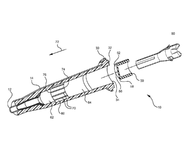
[0031] Referring now to Figure 3, an exploded, cross-sectional view of
an
intravascular device 10 is shown. In some embodiments, intravascular device 10
comprises a catheter adapter 14 having an inner surface 60 for receiving a
septum 50.
In some embodiments, inner surface 60 comprises a recessed groove having a
length
and depth sufficient to accommodate the length and outer diameter of septum
50.
Further, inner surface 60 may include one or more vents 70 which provide fluid
communication between a distal chamber 62 and proximal chamber 64 of the
catheter
adapter 14. For example, in some embodiments vents 70 permit passage of air
from
-Page 6-
CA 02828698 2013-08-29
WO 2012/121841 PCT/US2012/025051
distal chamber 62 to proximal chamber 64 thereby equilibrating air pressures
within
the adjacent chambers 62 and 64. This equilibration prevents buildup of air
pressure
within distal chamber 62 which may prevent a desirable flashback during
insertion of
catheter 12 into a patient.
[0032] In some embodiments, the one or more vents 70 are designed to
allow
the flow of air and stop the flow of blood. In some embodiments septum 50
comprises a single vent. In other embodiments septum 50 comprises a plurality
of
vents. For example, in some embodiments septum 50 comprises between two vents
and forty vents. Further, in some embodiments septum 50 comprises six vents.
[0033] In some embodiments, vents 70 further comprise a proximal
opening
74 and a distal opening 76. A cross sectional area of proximal and distal
openings 74
and 76 may be selected to permit or exclude passage of air and/or liquid
through vents
70. Accordingly, in some embodiments proximal and distal openings 74 and 76
comprise a cross sectional area between about 0.000007 to 0.00004 inches2. In
other
embodiments, the openings 74 and 76 have a cross sectional area between about
0.00001 to 0.00003 inches2. In other embodiments, openings 74 and 76 have a
cross
sectional area of about 0.00002 inches2. For instance, in some embodiments
openings
74 and 76 have a height of approximately 0.001 to 0.003 inches and a width of
approximately 0.010 inches. In other embodiments, openings 74 and 76 have a
height
of about 0.002 to 0.003 inches and a width of about 0.005 inches.
[0034] Similarly, vents 70 between the septum 50 and the inner surface
60 of
the catheter adapter 14 can be specifically configured to permit blood and air
to pass
therethrough at an estimated range of flow rates. For instance, in some
embodiments
vents 70 permit blood to flow therethrough at a rate between about 10 to 200
ml/hr.
In other embodiments, vents 70 permit blood to flow therethrough at a rate
between
about 15 to 150 ml/hr. In yet other instances, vents 70 permit blood to flow
therethrough at a rate between about 50 to 100 ml/hr. At these rates, the rate
of blood
flow into the proximal chamber 64 can be paced to provide a clinician with
adequate
time to correctly locate the catheter within a patient's blood vessel.
Accordingly, in
some embodiments, vents 70 have a cross sectional area greater than 0.00003
inches2.
In other embodiments, the vents 70 have a cross sectional area greater than
0.00004
inches2. In other embodiments, the vents 70 have a cross sectional area of
about
-Page 7-
CA 02828698 2013-08-29
WO 2012/121841 PCT/US2012/025051
0.0001 inches2. In other embodiments, the vents 70 have a cross sectional area
of
about 0.001 inches2.
[0035] With continued reference to Figure 3, in some embodiments
septum 50
comprises a membrane 52 which provides a defeatable barrier between distal and
proximal chambers 62 and 64. For example, in some embodiments membrane 52
comprises a slit 56 which is biased closed due to axial, compressive forces
applied to
the outer surface of septum 50 when fit into inner surface 60. In other
embodiments,
membrane 52 comprises a pierceable surface that may be defeated by a sharpened
instrument, such as a needle tip.
[0036] Generally, septum 50 comprises a hyperelastic material that,
when
assembled, interfaces with inner surface 60 through interference fit. In some
instances, the compressive forces experience by septum 50 in the assembly
intravascular device 10 cause the cross sectional area of vents 70 and
openings 74 and
76 to be deformed, wherein a portion of the septum 50 is forced into the
adjacent
vents 70. Accordingly, in some embodiments intravascular device 10 comprises
various compression relief features to compensate for compressive forces
experience
due to the interference fit.
[0037] Referring now to Figures 3 and 4, in some embodiments a distal
portion of septum 50 is modified to compensate for the aforementioned
deformation
due to compressive forces. For example, in some embodiments a chamfer 58 is
provided on the distal end of the outer surface of septum 50. In some
embodiments,
chamfer 58 tapers inwardly in a distal direction 72, wherein the length of
chamfer 58
corresponds approximately to the thickness 66 of membrane 52. In other words,
in
some embodiments chamfer 58 tapers inwardly from a proximal surface 68 of
membrane 52 to a distal surface 78 of membrane 52. Further, in some
embodiments a
radial distance of chamfer 58 is approximately equal to the maximum
deformation of
vents 70 under maximum expected compression when assembled. As such, the vent
geometry will experience minimal effect from compression, as shown in Figures
5 and
6.
[0038] Referring now to Figure 7, in some embodiments a plurality of
channels or vents 100 are provided in outer surface 102 of septum 150. Thus,
septum
150 may be positioned or seated within a catheter adapter 140 having a smooth
inner
-Page 8-
CA 02828698 2013-08-29
WO 2012/121841 PCT/US2012/025051
surface 120 which does not include channels or vents, as shown in Figures 8B
and
9A-10C, below. Thus, vent 100 provides fluid communication between distal and
proximal chambers 62 and 64, in accordance with the previous discussion.
Further,
vents 100 comprise distal and proximal openings 172 and 174 having respective
surface areas for accommodating passage of fluids, as previously discussed.
[0039] In some embodiments, a distal portion of vent 100 is chamfered
158 to
compensate for the aforementioned deformation due to compressive forces of the
interference fit. As shown in Figure 8A, prior to assembly chamfer 158
provides an
increased distal opening 172 which tapers outwardly in a proximal direction to
a final
vent depth 178. In some embodiments, compressive forces experienced at the
proximal end of septum 150 are less than compressive forces experienced at the
distal
end of septum 150. Accordingly, in some embodiments proximal opening 174 is
configured to have a cross section surface area approximately equal to the
cross
section surface area of vent 100 at vent depth 178. Thus, desirable final
geometries of
vent depth 178, distal opening 172 and proximal opening 174 are achieved
following
assembly of intravascular device 10, as shown in Figure 8B.
[0040] Referring now to Figure 9A, in some embodiments a distal
portion
160 of inner surface 120 is chamfered. As such, catheter adapter 140 may be
used
with a septum 180 having a non-chamfered distal outer surface 182, as shown.
Upon
assembly, surface 182 is deformed due to compressive forces, thereby causes
outer
surface 182 to be displaced into the chamfered portion 160 of inner surface
120, as
shown in Figure 9B. As such, the desirable final geometries of vent depth 178,
distal
opening 172 and proximal opening 174 are achieved.
[0041] In some embodiments, septum 250 comprises vent 200 having a
distal
opening272 with an initial cross section area that is greater than the desired
final cross
section area. Once assembled, compressive forces reduce the cross section area
of
opening 272, thereby achieving a desired final cross section area, as shown in
Figure
10B. Further, in some embodiments the desired final cross section area of
distal
opening 272 is equal to, or approximately equal to a desired final cross
section area of
the proximal opening 274, as shown in Figure 10C. Accordingly, the compression
relief features of the present invention compensate for compression forces
thereby
preventing occlusion or blockage of flow through the respective openings and
vents.
-Page 9-
CA 02828698 2013-08-29
WO 2012/121841 REPLACEMENT SHEET
PCT/US2012/025051
[0042] The
present invention may be embodied in other specific forms without
departing from its structures, methods, or other essential characteristics as
broadly
described herein and claimed hereinafter. The described embodiments are to be
considered in all respects only as illustrative, and not restrictive. The
scope of the
invention is, therefore, indicated by the appended claims, rather than by the
foregoing
description. All changes that come within the meaning and range of equivalency
of
the claims are to be embraced within their scope.
-Page 10-
SUBSTITUTE SHEET (RULE 26)