Note: Descriptions are shown in the official language in which they were submitted.
PRESSURE CORING ASSEMBLY AND
METHOD
This application claims benefit of US patent application number 61/453,232,
filed
March 16, 2011 and US patent application number 61/559,967, filed November 15,
2011.
BACKGROUND OF THE INVENTION
1. Field of the Invention
The present invention relates generally to coring tools and, more
particularly, to a
coring tool which provides a more accurate determination of the gas and
liquids in the
core even when the core is taken at significant depths and high pressure
formations.
2. Description of the Background
The goal behind a pressure coring tool is to bring an in situ sample of the
core to
surface. Ideally, the core would still contain all of the gas and various
fluids that the core
originally contained when captured at reservoir pressure. If the core samples
are the
same as they were when captured, subsequent measurements can be used to
estimate the
reserve gas in the formation.
However, problems arise with conventional coring tools because many presently
produced formations are at 10,000 feet and greater where pressures range from
7500 ¨
12000 psi.
One approach in the past to this problem has been to attempt to create a
chamber
and a valve that are capable of holding the high bottom hole pressures, as
well as the
fluids and gases, as the core is retrieved to the surface from 10000 feet or
more in a well
bore. However, such attempts have been unsuccessful due to numerous problems.
For example, after retrieval, the coring tool contained the very high and
dangerous
pressure on the surface. This makes the coring tool difficult to handle and
potentially
quite dangerous to the drilling crew as the core is removed from the well.
- 1 -
CA 2830213 2018-01-11
CA 02830213 2013-09-13
WO 2012/125454 PCT/US2012/028478
In some cases, the valve may malfunction and is kept open or partially open by
the core itself, thereby losing a significant amount of fluids and gases. A
malfunctioning
valve might also suddenly release pressure at the surface, which could produce
a
dangerous high pressure spray.
This prior art design requires a high pressure chamber and high pressure
valve,
which results in greatly limiting the volume of the retrieved core so that
only a one to two
inch diameter core might be obtained from an eight and one half inch borehole.
As well,
the cores from such tools were very short. Smaller cores are inherently less
desirable
and/or reliable for calculations.
Another approach has been to use estimation calculations, which were
successful
at shallower depths, e.g., for relatively shallow coal bed methane (CBM)
formations.
However, over the past years, new sources of natural gas formations have been
developed
at considerably greater depths and pressures for which the estimation
calculations are no
longer accurate. For example, a present trend involves producing shale gas
from the
deeper formations. To determine the amount of natural gas contained in the CBM
formations, the core was put into canisters after the core was brought to
surface. The
canisters were sealed but left at atmospheric pressure to allow all of the gas
to "bleed"
out. The gas was then measured. Through specifically derived calculations, the
amount
of gas the reservoir contained could be determined.
Wire line coring was a integral part of this equation because after cutting
the core,
the core could be retrieved to the surface within minutes, therefore
minimizing the gas
that was lost during the trip out of the hole. The amount of gas lost from the
time the
core was subjected to a lesser pressure than reservoir pressure (once tripping
out of the
well bore had begun) could only be estimated from calculations. As well, in
coal cores,
the gas "bleeds" out the core slowly. So when combined with the fast tripping
of wire
line coring, the back calculations were very accurate.
When the exploration of shale gas began, the gas community thought it would be
possible to apply the same calculations to shale and the problem would be
solved. There
were two major issues: (1) The new shale gas formations were at much greater
depths
- 2 -
CA 02830213 2013-09-13
WO 2012/125454 PCT/US2012/028478
than the shallow coal seams of CBM. This meant that the differential pressure
from
reservoir pressure to atmospheric was much greater, which forced more gas out
before
the core was at surface, and (2) Most of the new shale gas formations
contained as much
as 95% "free gas". This term means just what it suggests, 95% of the gas is
lost due to
the pressure decrease while tripping out of the hole, so it only leaves 5% to
be analyzed.
Back calculating with any degree of accuracy from the 5% content remaining in
the core
is virtually impossible.
Accordingly, it would be desirable to provide a pressure coring tool that
provides
improved capture of gas and fluids present when the core is initially taken at
down hole
depth and pressure. Consequently, there remains a long felt need for an
improved coring
tool. Those skilled in the art have long sought and will appreciate the
present invention
which addresses these and other problems.
SUMMARY OF THE INVENTION
It is an object of the present invention to provide an improved coring tool
which
provides larger cores and more accurate results even when working at
significant depths
and pressures.
It is one possible object of the present invention to provide a coring tool
that
utilizes the decreasing well bore drilling fluid pressure as the tool is
tripped out of the
hole to activate mechanisms for collecting fluids (gas and liquids) and/or
expelling fluids
from a core.
It is one possible object of the present invention to provide an improved
bottom
valve mechanism for sealing off the bottom of an inner core barrel prior to
retrieving the
core with wireline or drill pipe.
The present invention is not limited to use with wireline and could be
utilized for
drill pipe coring operations, where the entire tool is retrieved by tripping
the drill pipe.
When running the tool on the end of drill pipe, where the tool is retrieved by
tripping the
drill pipe in a conventional manner, the tool is capable of retrieving at
least three inch
diamter cores from 6 inch and larger hole sizes.
- 3 -
CA 02830213 2013-09-13
WO 2012/125454 PCT/US2012/028478
These and other objects, features, and advantages of the present invention
will
become apparent from the drawings, the descriptions given herein, and the
appended
claims. However, it will be understood that above-listed objectives and/or
advantages of
the invention are intended only as an aid in quickly understanding aspects of
the
invention, are not intended to limit the invention in any way, and therefore
do not form a
comprehensive or restrictive list of objectives, and/or features, and/or
advantages.
Accordingly, in one possible embodiment, the present invention provides a
coring
tool that allows retrieval of usable 3" cores in seven and seven-eights well
bore at high
pressures and depths. In this embodiment, because the chamber and valve do not
have to
contain very high pressure, significantly more room is available in the inner
barrel for the
core.
In one possible embodiment, a coring tool bottom valve in accord with one
possible embodiment of the invention moves the core out of the way of the
bottom valve
prior to closing the bottom valve.
In one possible embodiment, the core and/or the bottom valve are moved by tool
operation so that the bottom of the core moves above or toward the surface
before closing
the bottom valve to avoid problems with the core interfering with valve
operation.
In one possible embodiment, the core chamber pressure is allowed to decrease
as
the core tool is retrieved to a lower pressure utilizing a pressure
differential valve
mechanism in fluid communication with the coring chamber, that utilizes the
differential
pressure to push fluids and gas from the core into storage canisters during
the ascent.
This results in a lower pressure core chamber that is much safer to handle at
the surface
as well as capture of all or virtually all of the fluids and gases that were
originally in the
core sample when captured. In one embodiment, one or more 10 foot cores may be
obtained and/or the tool may be converted to one or more 30, 60, or 90 foot
standard
cores without the need to trip the pipe from the well.
In one possible embodiment, the present invention provides a vvireline or
drill
pipe operable coring tool, which may comprise elements such as, for example,
an inner
barrel which is operable to receive a core, a bottom coring tool valve
operable to seal off
- 4 -
CA 02830213 2013-09-13
WO 2012/125454 PCT/US2012/028478
a bottom of the inner barrel below the core and at least one pressure canister
operable to
receive fluid from the core in the inner barrel.
The wireline or drill pipe operable coring tool may further comprise at least
one
differential pressure operated valve which controls fluid communication from
the core in
the inner barrel to the at least one pressure canister.
In one possible embodiment, the bottom coring tool valve is responsive to
pulling
from the vvireline to close the bottom coring tool valve. Although, the
present invention
could possibly utilize other valve mechanisms to close the bottom of the inner
barrel, in
one embodiment the bottom valve is moveable relative to the core so that the
core is
above the bottom valve in the inner barrel prior to closing the valve to avoid
jamming of
the bottom valve operation by the core.
In one possible embodiment, the differential pressure operated relief valve
between the pressure canister and the inner barrel opens during the ascent to
the surface
to permit fluid communication between the at least one pressure canister and
the inner
barrel, which saves the fluids coming out of the core and at the same time
reduces the
pressure within the inner barrel to a safer level. Multiple differential
pressure operated
relief valves may be connected to operate sequentially to continue to save the
fluids and
maintain the pressure in the inner barrel at a safer level.
In one embodiment, the differential pressure operated relief valve(s) operate
.. responsively to a differential pressure between a well bore drilling fluid
column pressure
and a pressure inside the inner barrel.
The pressure canister may define a well bore opening that permits fluid
communication of the well bore drilling fluid pressure into the pressure
canister to
thereby provide the decreasing well bore drilling fluid pressure with respect
to pressure in
the inner core and/or in other pressure canisters. The differential pressure,
which is
limited to a desired level, e.g. 500 psi, so that at the surface atmospheric
pressure, the
inner barrel pressure is limited to a maximum of the desired pressure, e.g.,
500 psi.
While 500 psi is one possible optimal pressure, a limited pressure might be in
the range
- 5 -
CA 02830213 2013-09-13
WO 2012/125454 PCT/US2012/028478
of 400-600 psi in one embodiment, or 300-700 psi in another embodiment, or
generally
less than 1000 psi. However, other ranges could also be selected if desired.
The wireline or drill pipe operated coring tool may further comprise piston(s)
in
the pressure canister(s) that are moveable to a position to seal off the well
bore opening in
response to changing well bore drilling fluid pressure. By blocking off the
well bore
opening, well bore drilling fluid pressure is then utilized to operate the
next differential
pressure operated relief valve between the next pressure canister in the line.
Thus, the
wireline or drill pipe operated coring tool may, if desired, comprise multiple
pressure
canisters and multiple differential pressure operated relief valves which can
be connected,
if desired, to sequentially open as the coring tool is brought to the surface
and thereby
control fluid communication between the core and the multiple pressure
canisters.
In one possible embodiment, the bottom coring tool valve may comprise a
collapsible (rigid material such as metal or plastic or other hard material)
portion and an
electrometric tubular within the collapsible portion. The collapsible portion
may
comprise slots, indentions, openings, weakened regions, thinner regions and
the like. The
weakened portions of the collapsible portion cause the collapsible portion to
collapse into
a predetermined collapsed configuration which pinches off the elastomeric
material to
thereby seal the bottom coring tool valve by compressing the electrometric or
any
heat/fluid suitable flexible sealing material into a closed end. In another
embodiment,
the bottom hole coring valve might comprise a spring loaded flapper valve that
seals shut
and is further sealed off due to the differential pressure. In yet another
embodiment, the
bottom valve may comprise a ball valve.
In one possible embodiment, the wireline or drill pipe operated coring tool
may
further comprise a valve actuator to operate the valve and in one possible
embodiment
comprise means for moving the core above the valve prior to the valve closing
off the
bottom of the tool.
In another possible embodiment, the valve actuator comprises a lower activator
portion and an upper activator portion, which initially support the valve in
the open
position during coring. The upper activator portion and the lower activator
portion are
- 6 -
CA 02830213 2013-09-13
WO 2012/125454 PCT/US2012/028478
moveable with respect to each other, preferably in response to upward force
produced by
the wireline, to collapse the collapsible portion to thereby seal the bottom
coring tool
valve.
In another possible embodiment, the present invention provides a method for
making a vvireline or drill pipe operable coring tool, which may comprise
steps such as,
for example, providing an inner barrel which is operable to receive a core,
providing a
bottom coring tool valve operable to seal off a bottom of the inner barrel,
and providing
at least one pressure canister operable to receive fluid from the core in the
inner barrel.
The method may in one possible embodiment further comprise providing at least
one pressure canister valve between the press= canister and the inner barrel,
which
when open permits fluid communication between the at least one pressure
canister and
the inner barrel.
In one possible embodiment, the method may comprise utilizing decreasing well
bore drilling fluid pressure as the tool is retrieved to the surface to cause
fluid flow from
the core in the inner barrel to the at least one pressure canister.
In one possible embodiment, the method may comprise providing that the at
least
one valve is opened responsively to a differential pressure between the
pressure canister
and the core in the inner barrel.
The method may comprise providing that the bottom coring tool valve is
moveable with respect to the core in the inner barrel to a position below the
core in the
inner barrel.
BRIEF DESCRIPTION OF THE DRAWINGS
A more complete understanding of the invention and many of the attendant
advantages thereto will be readily appreciated as the same becomes better
understood by
reference to the following detailed description when considered in conjunction
with the
accompanying drawings, wherein like reference numerals refer to like parts and
wherein:
Fig. lA is an elevational view showing an external view of a coring tool in
accord with one possible embodiment of the present invention;
- 7 -
CA 02830213 2013-09-13
WO 2012/125454 PCT/US2012/028478
Fig. 1B is an elevational view, in section, showing a coring tool with labeled
internal elements in accord with one possible embodiment of the present
invention;
Fig. 2A is an elevational view, in section, showing the core capture operation
wherein the core is initially captured within the inner barrel and held in
place therein by
the core catcher in accord with one possible embodiment of the present
invention;
Fig. 2B is an elevational view, in section, showing the core capture operation
wherein the canisters and inner bane! of the inner coring tool are pulled
upwardly (e.g.
using wireline) whereby the core moves upwardly with respect to the outer
barrel of the
coring tool and a bottom valve such that the bottom valve is then positioned
below the
core in accord with one possible embodiment of the present invention;
Fig. 2C is an elevational view, in section, showing the core capture operation
wherein the bottom valve in the coring tool that is now located below the core
closes to
seal off the bottom of the coring tool in accord with one possible embodiment
of the
present invention;
Fig. 2D is an elevational view, in section, showing the core capture operation
wherein as the wireline continues to pull at the top of the inner coring tool,
the bit/shank
latch releases, and the coring tool containing the core initially at high
pressure of the
bottom hole wellbore pressure can then be pulled out of the well bore in
accord with one
possible embodiment of the present invention;
Fig. 3A is an elevational view, in section, showing the pressure canister
operation
as the coring tool ascends but prior to operation of the first canister relief
valve as the
wireline or drill pipe tool pulls the inner coring tool up the borehole so
that the well bore
drilling fluid pressure decreases until reaching the desired differential
pressure which
operates the relief valve in accord with one possible embodiment of the
present
invention;
Fig. 3B is an elevational view, in section, showing the pressure canister
operation
as the wireline or drill pipe tool pulls the inner coring tool up the borehole
so that the well
bore drilling fluid pressure decreases, thereby increasing the differential
between the
canister and the core in the inner barrel until the relief valve opens to
thereby collect fluid
- 8 -
CA 02830213 2013-09-13
WO 2012/125454
PCT/US2012/028478
(liquid and gas) from the core into the canister, which operates a piston in
the canister, in
accord with one possible embodiment of the present invention;
Fig. 3C is an elevational view, in section, showing the pressure canister
operation
as the wireline or drill pipe tool pulls the inner coring tool up the borehole
so that as the
well bore drilling fluid pressure decreases the fluid (gas and liquids) from
the core fill the
canister, pushes the canister piston until the canister piston blocks the well
bore drilling
fluid pressure vent, whereby the second relief valve of the second canister is
now subject
to differential pressure changes, and upon reaching the desired differential
pressure, the
second relief valve opens to allow fluid flow into the second canister (and
likewise
additional canisters) to collect fluid and gas from the core in multiple
canisters in accord
with one possible embodiment of the present invention; FIG.
4A is a perspective view showing the external surface of a bottom valve when
the bottom
valve is in the open position in accord with one possibleembodiment of the
present
invention; FIG. 48
is a perspective view, in section,
showing internal surfaces of bottom valve when the bottom valve is in the open
position
in accord with one possible embodiment of the present invention;
FIG. 5A is a perspective view showing the external surface of a bottom valve
when the bottom valve is in the closed position in accord with one
possibleembodiment
of the present invention; FIG.
5B is a perspective view, in
section, showing internal surfaces of a bottom valve when the bottom valve is
in the
closed or sealed position in accord with one possible embodiment of the
present
invention;
FIG. 6A is a perspective view showing the external surfaces of a possible
bottom
valve activator with bottom valve contained therein while the bottom valve
actuator
.. supports the bottom hole valve in the open position in accord with one
possible
embodiment of the present invention;
FIG. 6B is a perspective view, in section, showing the internal surfaces of a
bottom valve activator with bottom valve contained therein while the bottom
valve
- 9 -
CA 02830213 2013-09-13
WO 2012/125454 PCT/US2012/028478
actuator supports the bottom hole valve in the open position in accord withone
possible
embodiment of the present invention;
FIG. 7A is a perspective view showing external surfaces of a bottom valve
activator with bottom valve contained therein after the bottom valve activator
components are moved to place the bottom valve in the closed or sealed
position in
accord with one possible embodiment of the present invention;
FIG. 7B is a perspective view, in section, showing internal surfaces of a
bottom
valve activator with bottom valve contained therein after the bottom valve
activator
components are moved to place the bottom valve in the closed or sealed
position in
accord with one possible embodiment of the present invention;
FIG. 8 is an elevational view, in section, showing an overview of an
underground
pay zone with a proposed coring program in accord with one possible embodiment
of the
present invention;
FIG. 9 is an elevational schematical view showing another possible embodiment
of a coring tool in accord with one possible embodiment of the present
invention;
FIG. 10 is an elevational view that is an enlarged upper section of FIG. 9
showing
a swivel section of a coring tool in accord with one possible embodiment of
the present
invention;
FIG. 11A is an elevational view that is an enlarged middle section of FIG. 9
showing a fluid canister section of a coring tool in accord with one
possibleembodiment
of the present invention;
FIG. 11B is an elevational view that is an enlarged lower section of FIG. 9
showing a core barrel portion of a coring tool in accord with one
possibleembodiment of
the present invention;
FIG. 12A is an elevational view that is an outer view of a coring tool prior
to
stroking the tool to move the bottom of the core above the bottom valve in
accord with
one possible embodiment of the present invention;
-10-
CA 02830213 2013-09-13
WO 2012/125454 PCT/US2012/028478
FIG. 128 is an elevational view, partially cutaway, of a coring tool prior to
stroking the tool to move the bottom of the core above the bottom valve in
accord with
one possible embodiment of the present invention;
FIG. 12C is an elevational view, partially cutaway, of a coring tool in an
initial
stage of stroking the tool to move the bottom of the core above the bottom
valve in
accord with one possible embodiment of the present invention;
FIG. 12D is an elevational view, partially cutaway, of a coring tool in an
initial
stage of stroking the tool to move the bottom of the core above the bottom
valve in
accord with one possible embodiment of the present invention;
Fig. 13A is an elevational view, in section, showing the pressure canister
operation in an initial stage of operation as the coring tool ascends as the
wireline or drill
pipe tool pulls the inner coring tool up the borehole so that the well bore
drilling fluid
pressure decreases in accord with one possible embodiment of the present
invention;
Fig. 13B is an elevational view, in section, showing the pressure canister
operation as the wireline or drill pipe tool pulls the inner coring tool up
the borehole so
that the well bore drilling fluid pressure decreases, thereby increasing the
differential
between the canister and the core in the inner barrel until the relief valve
opens to thereby
collect fluid (liquid and gas) from the core into the canister, which operates
a piston in
the canister, in accord with one possible embodiment of the present invention;
Fig. 13C is an elevational view, in section, showing the pressure canister
operation as the wireline or drill pipe tool pulls the inner coring tool up
the borehole so
that as the well bore drilling fluid pressure decreases the fluid (gas and
liquids) from the
core fill the canister, pushes the canister piston until the canister piston
blocks the well
bore pressure vent, whereby the second relief valve of the second canister is
now subject
to differential pressure changes, and upon reaching the desired differential
pressure, the
second relief valve opens to allow fluid flow into the second canister (and
likewise
additional canisters) to collect fluid and gas from the core in multiple
canisters in accord
with one possible embodiment of the present invention;
-11-
CA 02830213 2013-09-13
WO 2012/125454 PCT/US2012/028478
FIG. 14A is an elevational view showing a bottom valve for a coring tool in
accord with one possible embodiment of the present invention;
FIG. 14B is an elevational view, partially in section showing a bottom valve
for a
coring tool in accord with one possible embodiment of the present invention;
FIG. 15A is an elevational view showing a bottom valve for a coring tool prior
to
stroking the tool to move the bottom of the core past the bottom valve in
accord with one
possible embodiment of the present invention;
FIG. 15B is an elevational view showing a bottom valve for a coring tool in an
initial stage of stroking the tool to move the bottom of the core past the
bottom valve in
accord with one possible embodiment of the present invention;
FIG. 15C is an elevational view showing a bottom valve for a coring tool which
is
closing after stroking the tool to move the bottom of the core past the bottom
valve in
accord with one possible embodiment of the present invention;
FIG. 15D is an elevational view, partially in dashed lines, showing a bottom
valve
for a coring tool closed after stroking the tool to move the bottom of the
core past the
bottom valve in accord with one possible embodiment of the present invention;
FIG. 16A is an elevational view showing the coring tool retrieved from the
borehole prior to recovering the core in accord with one possible embodiment
of the
present invention;
FIG. 16B is an elevational view showing the coring tool of FIG. 16A with the
swivel section removed in accord with one possible embodiment of the present
invention;
FIG. 16C is an elevational view showing the coring tool of FIG. 16A with the
canister section removed in accord with one possible embodiment of the present
invention;
FIG. 16D is an elevational view, partially in section, showing the coring tool
of
FIG. 16C with the core therein in accord with one possible embodiment of the
present
invention;
- 12 -
CA 02830213 2013-09-13
WO 2012/125454 PCT/US2012/028478
FIG. 17A is an elevational view showing the coring tool of FIG. 16C with an
electronic connection to retrieve pressure and temperature data from a
recording module
in accord with one possible embodiment of the present invention;
FIG. 1713 is an elevational view showing the coring tool of FIG. 16C with
pressure line connected to the core pressure to bleed off core gases in accord
with one
possible embodiment of the present invention;
FIG. 18A is an elevational view, partially in section, showing the coring tool
of
FIG. 16C with pressure bled off prior to removing the core in accord with one
possible
embodiment of the present invention;
FIG. 18B is an elevational view, partially in section, showing the coring tool
of
FIG. 18A with the recording module removed prior to removing the core in
accord with
one possible embodiment of the present invention;
FIG. 18C is an elevational view, partially in section, showing the coring tool
of
FIG. 18B as the core is removed in accord with one possible embodiment of the
present
invention;
FIG. 19A is an elevational view, partially in section, showing a piston
inserted
into the tool after the core is removed to retrieve remaining fluid in accord
with one
possible embodiment of the present invention;
FIG. 19B is an elevational view, partially in section, showing the piston of
FIG.
19A moved through the tool to retrieve fluid in accord with one possible
embodiment of
the present invention;
FIG. 19C is an elevational view, partially in section, showing the piston of
FIG.
19A continuously moved through the tool to retrieve fluid in accord with one
possible
embodiment of the present invention;
FIG. 19D is an elevational view, partially in section, showing the captured
fluid
remaining in the core barrel after removal of the core retrieved in accord
with one
possible embodiment of the present invention;
- 13 -
CA 02830213 2013-09-13
WO 2012/125454 PCT/US2012/028478
FIG. 20A is an elevational view showing the canister with an electronic
connection to retrieve pressure and temperature data from a recording module
in accord
with one possible embodiment of the present invention;
FIG. 20B is an elevational view showing the canister with a pressure hose
connection to bleed off gas in accord with one possible embodiment of the
present
invention;
FIG. 20C is an elevational view, partially in section, showing the canister
with a
pressure hose connection to retrieve the recovered fluids in the initial stage
of recovery in
accord with one possible embodiment of the present invention;
FIG. 20D is an elevational view, partially in section, showing the canister
with a
pressure hose connection to retrieve the recovered fluids midway through the
recovery
process in accord with one possible embodiment of the present invention;
FIG. 20E is an elevational view, partially in section, showing the canister
with a
pressure hose connection to retrieve the recovered fluids in accord with one
possible
embodiment of the present invention.
While the present invention will be described in connection with presently
preferred embodiments, it will be understood that it is not intended to limit
the invention
to those embodiments. On the contrary, it is intended to cover all
alternatives,
modifications, and equivalents included within the spirit of the invention and
as defined
in the appended claims.
DETAILED DESCRIPTION OF THE PREFERRED EMBODIMENTS
The present invention can be utilized to capture the fluid and gas of larger
cores
of shale formations taken at higher pressures and depths. Most of the shale
gas reservoirs
are at 7000 to 12000 psi.
In one embodiment, the present invention utilizes decreasing well bore
drilling
fluid pressure as the core moves up the wellbore to activate coring assembly
mechanisms
- 14 -
CA 02830213 2013-09-13
WO 2012/125454 PCT/US2012/028478
to collect all or essentially all the gas and liquids that are expelled while
the core is
tripped out of the hole.
In one embodiment, the present invention avoids the problem of holding the
core
at high reservoir pressures, which are dangerous at the surface.
In one possible embodiment, the coring tool of the present invention provides
a
bottom valve mechanism which allows capturing the core and closing the bottom
of the
inner barrel after coring is completed. but prior to lifting off the bottom of
the well bore.
Referring to FIG. 1A, there is shown an external view of one possible
embodiment of coring tool 10, which includes outer body 12 and core bit 14.
Outer body
12 is rotated by the drill sluing, which in turn rotates core bit 14 as is
well known in the
art. In one possible embodiment, coring bit 14 may drill a 7 7/8 inch diameter
hole and
still retrieve a relatively large three inch diameter core. In one embodiment,
the core
length retrieved under the high pressure conditions as discussed above may be
ten feet
and/or the coring tool could be converted to a 30, 60, or 90 foot standard
core without
tripping the drill pipe to change the outer barrel of the coring tool.
FIG. 1B shows various components within the embodiment of FIG. 1A, but it will
be understood that the invention is not limited to this particular
configuration. Pressure
canister 16 is positioned above inner barrel 20 to receive fluids including
gas and liquids.
As discussed hereinafter, piston 18 moves in response to a differential
pressure as the
inner barrel components of coring tool 10 are retrieved by vvireline or drill
pipe. Wireline
or drill pipe retrieval of coring tools is well known in the art. Core catcher
22 may be
utilized to secure the core in position. Bottom valve and valve actuator
mechanism 24,
which may be of various types, is utilized to tightly seal off the bottom of
inner barrel 20.
In one possible embodiment, bit/shank latch 26 and/or other latches may be
utilized to
secure the internal components of coring tool 12 in position during drilling
and to provide
tension on valve actuator mechanism 24 when pulling with the wireline to
operate valve
actuator mechanism 24.
FIG. 2A, 2B, 2C, and 2D show an overview of a sequence of core capture
operation in accord with one possible non-limiting embodiment of the
invention. In FIG.
- 15 -
CA 02830213 2013-09-13
WO 2012/125454 PCT/US2012/028478
2A, core 28, which may be a ten foot three inch diameter core, is captured
during coring
and held in place with core catcher 22. Core 28 may be captured in a high
pressure
formation.
In FIG. 2B, wireline pull as indicated by arrow 30 is utilized to pull one or
more
canisters 16 and inner barrel 20 upwardly or toward the surface with respect
to outer
barrel 12. In this embodiment, core catcher 22 or other component may be
utilized to
engage an activation sleeve for the bottom valve and valve actuator mechanism
24, some
examples of which are discussed hereinafter. It will be noted that during this
initial
operation, bottom 32 of core 28 is moved upwardly above bottom valve and valve
actuator 24 while bit/shank latch 26 remains engaged.
In FIG. 2C, additional pulling upwards with the wireline as indicated by arrow
30
with bit/shank latch still engaged creates tension in bottom valve and valve
actuator
mechanism that results in closing bottom valve and valve actuator mechanism 24
as
indicated by the closed portion 34 of the bottom valve. As discussed
hereinafter, various
embodiments for the bottom valve may be utilized.
In FIG. 2D, additional pulling upward with the wireline as indicated by arrow
30
releases bit/shank latch 26 and the inner coring tool can now be pulled out of
the hole
through the drill pipe. Essentially, the length of the retrievable portion of
the coring tool
is expanded or increased during this process so that the bottom of the core is
moved out
of the way of the bottom valve for more reliable valve operation.
In this embodiment, the core is moved out of the way of the bottom valve by
movement of the tool. In another embodiment, the core may be cut off above the
bottom
valve and/or any remaining core is flushed out of the way of the bottom valve
by
directing circulating fluid thought the bottom valve prior to closing the
bottom valve.
However, the tool may be moved to cause a change in direction of the
circulation fluid
through the bottom valve, if desired. In other words, the disclosed
embodiments provide
an inventive concept that may be implemented in different mechanical ways.
Additional
embodiments are discussed hereinafter.
-16-
CA 02830213 2013-09-13
WO 2012/125454 PCT/US2012/028478
As the tool is pulled upwardly toward the surface, the well bore drilling
fluid
pressure decreases, thereby increasing the relative pressure within captured
core 28. FIG.
3A, FIG. 3B, and FIG. 3C illustrate one possible embodiment the general
operation of
one or more pressure canisters 16 as the tool moves towards the surface.
In FIG. 3A one embodiment of fluid canister 16 is shown, which is utilized to
capture gases and/or fluids from the captured core. In this embodiment,
canister 16 may
comprise canister outer housing 56. Canister top sub 48 and canister bottom
sub 44 may
be threadably attached to canister outer housing 56. Inner barrel 20 may be
threadably
secured to bottom sub 44 utilizing inner barrel connector 46. Canister bottom
sub 44 may
have canister bottom relief valve 36 mounted therein and canister top sub 48
may have
canister top relief valve 50 built therein.
Core pressure, as indicated by arrow 42, from the sealed inner core barrel 20
due
to captured core 28 is applied to canister bottom relief valve 36. Once the
operational
differential pressure of relief valve 36 is reached, which may be in the range
of 500 psi or
other desired canister pressure as discussed earlier, then core pressure 42 is
applied to
lower side 52 of piston 18 through vent 59 in tube 60. The other end of tube
60 is sealed
off by canister top relief valve 50. In one embodiment, well bore drilling
fluid pressure
as indicated by arrow 40, which is applied to the top side 54 of piston 18
enters into
canister outer housing 56 through wellbore vent 38. Thus, wellbore fluid and
pressure
engages top side 54 of piston 18. However, the well bore drilling fluid
pressure may be
passed through pressure reducers, applied to pistons, and/or the like as
desired.
Referring to FIG. 3B, as canisters 16 are pulled towards the surface, the well
bore
drilling fluid pressure decreases causing the relatively higher core pressure
and fluid 62
to move piston 18 as shown and enter canister 16 adjacent bottom side 52 of
piston 18.
__ Essentially, the region below piston 18 forms an expandable chamber in
which the fluid
(gases/liquids) from the core is received. Piston 18 has upper seals 58 and
lower seals
57, which seal with an interior surface of canister outer housing. In this
embodiment,
piston 18 also has interior seals 51, which seal around tube 60.
- 17-
CA 02830213 2013-09-13
WO 2012/125454 PCT/US2012/028478
In FIG. 3C, due to the continuously decreasing well bore drilling fluid
pressure,
piston 18 has been moved to the end of canister outer housing 56, so that the
expandable
chamber below piston 18 is now completely filled with core fluid 62. Upper and
lower
seals 58 and 57 seal off wellbore vent 38. While the pressure within canister
56 has been
limited due to well bore drilling fluid pressure due to vent 38, at this time
with wellbore
vent 38 sealed off, the differential pressure across canister top relief valve
50 increases
until valve 50 opens and the next canister, which is similar to canister 16
starts to fill in
the same way. The number of canisters may be selected to ensure capture of all
core
fluid and/or may be vented to the wellbore in a final stage. One way relief
valves,
different relief valve opening pressures, additional valves controlled by
piston 18
movement, and the like may be utilized, if desired, to close off the filled
canisters and/or
provide additional controls.
In another embodiment, flow tube 60 may be eliminated and the length of
canister
16 may increased although this increases the weight of the canister. in
another
embodiment, the canister may simply be an extension of the inner barrel with a
piston
provided to form an expandable chamber. Accordingly, the disclosed embodiments
illustrate an inventive concept of operation which may be implemented in
different ways.
FIG. 4A, FIG. 48, FIG. 5A and FIG. 58 show one possible embodiment for
bottom valve 23, which is part of bottom valve and valve actuator 24 discussed
hereinbefore. Other particular embodiments for a bottom valve are shown, for
example,
in FIG. 15A, FIG. 15B, FIG. 15C, and FIG. 15D. However, other types of valves
such as
ball valves, or the like may, also be utilized. Accordingly, the invention is
not limited to
a particular type of bottom valve.
FIG. 4A shows bottom valve 23 prior to operation. In this embodiment, bottom
valve 23 includes collapse tube 27, which collapses along at weakened sections
29, 31,
and 35 which encircle bottom valve 23 in response to compressive force applied
across
bottom valve 23 as indicated by arrow 39. The collapsed valve is shown in FIG.
5A,
whereby core pressure, as indicated by core pressure arrows 41 is trapped
within the
inner core barrel. The collapsible metallic sections 37 and 33 are pressed
inwardly
- 18 -
CA 02830213 2013-09-13
WO 2012/125454 PCT/US2012/028478
thereby squeezing tubular inner elastomeric element 25 at closed off region
34. FIG. 4A
shows a sectional view of inner elastomeric element 25 within collapse tube 27
prior to
operation and FIG. 5A shows a sectional view of closed bottom valve or seal 34
after
collapse tube 27 has been collapsed thereby pinching elastomeric element 25
tightly
closed.
FIG. 6A, FIG. 6B, FIG. 7A, and FIG. 7B show valve actuator 70, across which
tension is applied as the wireline pulls upwardly and bit/shank latch remains
engaged.
Valve actuator 70 comprises upper actuator 72 and lower actuator 74, which
slide with
respect to each. In this embodiment, upper actuator 72 and lower actuator 74
comprise
mating fingers 76 and 78, which slide with respect to each other in response
to the coring
tool being pulled upwardly by the wireline. FIG. 6A shows a cut away of bottom
valve
23 within valve actuator 70 prior to the operation of closing the valve.
Fasteners 82 and 84 may be utilized to connect valve actuator 70 to upper and
lower portions of bottom valve 23 with the collapsible portions being
positioned
therebetween. As shown in FIG. 7A, when the wireline pulls the coring tool
upwardly,
fingers 76 and 78 slide with respect to each other thereby collapsing bottom
valve 23 and
producing the collapsed valve seal region 34 as shown in FIG. 7B. Seal 80 may
be
utilized between upper actuator 72 and bottom valve 23 to prevent leakage to
the
wellbore. Additional force by the wireline releases the bit/shank latch 26 and
the coring
tool is pulled out of the well.
FIG. 8 shows one embodiment of a program for coring underground zone of
interest 86. In this embodiment, four 27 meter (90 feet) 3" standard wire line
cores are
taken and three 3 meter (10 feet) 3" inch pressure cores are taken.
Accordingly, a good
sample of core pressures and fluids is provided to make calculations. As well,
the actual
formation matrix over the entire zone is provided.
FIG. 9 shows coring tool 100, which is another possible embodiment of the
present invention. In FIG. 9 and FIG. 10, fishing neck 102 is provided at the
top of the
retrievable portion of coring tool 10 to provide an overshot connection for
retrieving the
core. Flow nozzles 104 may or may not be utilized for fluidly latching the
coring tool
- 19 -
CA 02830213 2013-09-13
WO 2012/125454 PCT/US2012/028478
into position and/or or other purposes as is known in the art. Landing seat
106 is
provided as a shoulder which supports the wireline retrievable portion of
coring tool 100
in the desired axial position with respect to outer barrel 116. Threads 114
may be utilized
for securing coring tool 100 to the drill pipe or the like.
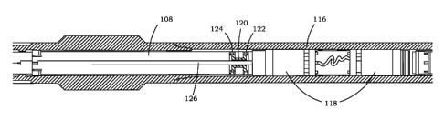
FIG. 9 and FIG. 11A show another embodiment of gas storage canister 108 and/or
other canisters, which may be utilized to store the reduced pressure gas from
the core as
discussed generally hereinbefore. In one possible embodiment, gas storage
canister 108
may be removed from the tool and transported to the lab for analysis and/or be
analyzed
with an onsite lab. In one possible embodiment, one or more
pressure/temperature
recording modules 118 may be utilized to monitor pressure, temperature, time,
and/or
other variables within the inner barrel and/or pressure canister and/or the
wellbore. FIG.
11A also shows piston 120, with upper and lower seals 124 and 122 as well as
gas flow
passageway 126.
FIG. 9 and FIG. 11B show inner core barrel 110, which may be utilized to
retrieve
core 128. In one possible embodiment, outer barrel 116 contains inner core
barrel 110,
which may comprise relatively sliding members, concentrically or telescopingly
arranged
members and/or the like to allow the bottom of the core to be moved past
bottom valve
136 in a manner similar to that discussed hereinbefore. In this embodiment,
these
members may be telescoping with respect to each other to allow the tool to
"stroke" as
described generally earlier and discussed hereinafter, during which time the
core is
moved away from and upwardly past bottom valve mechanism 112 prior to closing
the
valve. Core catcher 130 and bottom valve 112 (and valve actuator) are utilized
to secure
core within core barrel 110 and seal off the lower end of inner core barrel
110 when the
core is retrieved. Bit/shank latch 134 is also provided to hold the bottom of
the coring
tool in position during stroking when the expandable tool is pulled upwardly
by the
wireline.
FIG. 12A, FIG. 12B., FIG. 12C, and FIG. 12D, shows the sequence of activating
bottom valve 136 of coring tool 100. In this embodiment, the sliding or
stroking
operation of the tool is similar to that of the embodiment of FIG. 2A, FIG.
2B, FIG. 2C,
- 20 -
CA 02830213 2013-09-13
WO 2012/125454 PCT/US2012/028478
and FIG. 2D for coring tool 10 during which time the core is moved past the
bottom
valve before closing. In this embodiment, a different bottom valve mechanism
is utilized.
However, it is to be understood that other types of bottom valves such as ball
valves or
the like may be utilized more reliably due to the stroking function whereby
the bottom of
the core moves out of the way of the moveable members of the bottom valve
before the
valve closes.
FIG. 12A shows an external view of coring tool 100. In FIG. 12B, the wireline
is
run down and latched to the top of the retrievable portion of coring tool 100.
An up hole
directed force is produced as indicated by upwardly drawn arrow 138. In this
embodiment, core catcher mandrel 170 is telescopingly or concentrically
mounted and
sealed within sealing tube 198, which also seals around the body of bottom
valve 136.
In FIG. 12C, the tool begins to stroke to allow the core to move past bottom
valve 136,
whereby core catcher mandrel 170 is telescopingly, concentrically and/or
sliding partially
pulled out of sealing tube 198 or stroked as indicated by distance arrow 146.
The
relatively sliding members, as discussed hereinafter, may be utilized to
produce a tool
stroking effect as discussed earlier with respect to the valve actuator shown
in FIG. 6A
and FIG. 7A. During this process, the axial length of the inner barrel is
expanded or
increased.
In one possible embodiment, bit/shank latch 134 remains engaged throughout
this
process. After coring tool is fully stroked as indicated by distance 148, then
force is
exerted on bit/shank latch 134 to thereby release bit/shank latch 134. When
full stroking
is distance 148, then stops or shoulders between sealing tube 198 and core
catcher
mandrel 170 engage to prevent further expansion. In one embodiment, sealing
tube is
secured to bottom valve 136. At this time, upwardly directed force 138 is
applied to
bit/shank latch 134 to release bit/shank latch 134 and allow coring tool 100
(except for
the outer barrel components) to be pulled out of the borehole, with inner
barrel 110 sealed
off at the bottom end thereof by bottom valve 136. In one embodiment, the
expanded
inner barrel length or stroking distance 148 may be in the range between one
and two feet
or somewhat more or less as desired. In one embodiment, distance 148 may be
twenty
-21-
CA 02830213 2013-09-13
WO 2012/125454 PCT/US2012/028478
inches plus or minus twelve inches or plus or minus six inches or somewhat
more or less
as desired for reliable operation of bottom valve 136 after the bottom of the
core passes
therethrough, as discussed hereinbefore and/or hereinafter.
As the inner barrel is pulled out of the hold, the fluid canister begins to
operate as
discussed hereinbefore. FIG. 13A shows another possible embodiment of fluid
storage
canister 108. In this embodiment sealed core pressure is applied to one end of
fluid
storage canister 108 as indicated at arrow 150. In one embodiment, this
pressure
overcomes a lower relief valve, which may be a one-way valve, as the tool
moves
towards the lower well bore drilling fluid pressure at the surface. The relief
valve
activation pressure may be set at 500 psi, plus or minus a range of 50 to 500
psi or more
or less, as discussed hereinbefore. In another embodiment a one-way valve may
be
utilized to seal the bottom of fluid canister 108 for retrieval purposes as
discussed
hereinafter. The desire is to have a relatively safe working pressure at the
surface. As
discussed hereinbefore, piston 120 is sealed at the interior side by inner
seals 123, which
seal around tube 126. Outer upper seal 124 and outer lower seal 122 seal
around the
circumference of piston 120.
Once the relief valve pressure is overcome, assuming a relief valve is
utilized,
then core fluids 232 such as gas/liquid flow from the core into opening 152 in
fluid flow
passageway tube 126 (or another tube if desired) at the lower side of piston
120 as
indicated by core pressure fluid flow arrow 154. The other end of fluid flow
passageway
tube 126 is closed utilizing upper relief valve 156, which may be set to a
desired relief
valve pressure operation the same as or higher than the lower relief valve
and/or one way
valve.
As discussed hereinbefore, the core fluid pressure as indicated by arrow 154
may
be offset by well bore drilling fluid pressure as indicated by arrow 158 or a
derivative
thereof, which may flow through wellbore opening 160 into upper chamber 163 of
gas
storage canister 108 and is applied at the upper side of piston 120.
Additional wellbore
openings 161 from the wellbore into upper chamber 163 of gas storage canister
may be
utilized, if desired.
- 22 -
CA 02830213 2013-09-13
WO 2012/125454 PCT/US2012/028478
Pressure and temperature of the irmer barrel and/or one or more canisters
and/or
wellbore fluids, and other desired measurable parameters, may be monitored by
various
sensors such as temperature/pressure sensor 162 and recorded by recording
module 118.
Plugs and/or other sensors 164 may be utilized to seal and/or measure well
bore drilling
fluid pressure/temperature and/or other parameters. Pressure hose 166 may lead
to
another recording module and/or another gas storage canister, as discussed
hereinbefore.
In FIG. 13B, as the gas storage canisters are pulled out of the hole toward
the
surface, well bore drilling fluid pressure 158 decreases. Accordingly, the
volume of core
fluid 232 expands as the core fluid pressure 152 causes piston 120 to move in
the
direction indicated by arrow 168, which in one possible embodiment is up hole
towards
the top of the tool. Accordingly, an expandable chamber is provided to receive
fluid
from the core.
As shown in FIG. 13C, once piston 120 reaches the end of the chamber of gas
storage canister, the differential pressure between continuously dropping well
bore
drilling fluid pressure and sealed core pressure increases as discussed
hereinbefore until
upper relief valve 156 opens. The core fluid 232 and pressure then goes
through gas flow
passageway 126 as indicated by arrow 157 and pressure hose 166 as the core
pressure
escapes into the next canister and the process repeats itself.
FIG. 14A and FIG. 14B show another possible embodiment of bottom valve 136,
which in this embodiment utilizes core catcher mandrel 170 and core float seal
body 172.
Outer sealing tube 198, which telescopingly seals around core catcher mandrel
170 and
also seals around core float seal body 172 is removed for easier viewing.
In FIG. 14A, flapper valve element 174 is pivotally attached to core float
seal
body 172 with spring-loaded hinge 176. The inner surface of flapper valve
element 174
is cylindrical and mates with the outer surface of catcher mandrel lower tube
178 to
protect flapper valve element 174 from damage.
In FIG. 14B, which is partially shown in cross-section, it can be seen that
lower
tube 178 slidingly and/or telescopingly extends into bore 180 of core float
seal body 172
and in this embodiment may seat at shoulder 184. Bore 180 and bore 182 may
preferably
- 23 -
CA 02830213 2013-09-13
WO 2012/125454 PCT/US2012/028478
be the same internal diameter and in combination form a smooth unrestricted
bore for
receipt of core 128.
Flapper valve element 174 has a contour at periphery 186, which mates to a
contour at top sealing surface 188 of core float seal body 172. The periphery
of flapper
valve 174 and/or top sealing surface 188 may comprise high
temperature/pressure sealing
material, such as elastomeric material, bonded rubber, metallic rib/groove
metallic seals,
soft material seals, other metal seals, or other types of seals. In this
embodiment, the
mating contour is rounded. It will be appreciated that considerable sealing
force will
result on flapper valve element 174 to hold flapper valve element 174 against
top sealing
surface 188 because the pressure in catcher mandrel is maintained at about 500
psi
relative to atmospheric pressure, as discussed hereinbefore, and the diameter
of the core
may be in the range of about three inches.
FIG. 15A, FIG. 15B, FIG. 15C, and FIG. 15D show the steps of bottom valve 136
activation. In FIG. 15A, the bottom valve is in the position shown in FIG. 14A
with
flapper element 174 held open by the outer surface of catcher mandrel lower
tube 178.
Stroking has not started as shown in FIG. 12B. However, assuming that the
coring is
completed, the core may then be broken.
In FIG. 15B, force is applied with the overshot and wireline in the direction
of the
surface as indicated by wireline force direction arrow 194. Catcher mandrel
lower tube
178 is removed from the bore 180 of core float seal body. Core 128, which may
extend
below the bottom end 196 of catcher mandrel lower tube 178 continues to hold
flapper
valve element 174 open. Additional means such as rod or extension of lower
mandrel
tube 178 may also be utilized to hold flapper valve element 174 open until the
bottom end
192 of core 128 is reached.
In FIG. 15C, bottom end 192 of core 128 moves out of the way of flapper
element
174 so that spring-loaded hinge 176 helps close flapper element 174.
In FIG. 15D, flapper element 174 engages top sealing surface 188 of core float
seal body 172, which seals off the bottom of the core barrel. The force on
flapper
- 24 -
CA 02830213 2013-09-13
WO 2012/125454 PCT/US2012/028478
element 174 increases to tighten the seal even more as the coring tool is
pulled out of the
hole by wireline or conventionally tripped by drill pipe.
In one possible embodiment, sealing tube 198 (See also FIG. 12 B and FIG.
16A),
as indicated by dashed lines in FIG. 15D, surrounds and seals off core catcher
mandrel
170 and core float seal body 172. Seals, such as seals 201 and 202 may be
utilized. As
well, stops such as stop 204 and shoulder 206 may be utilized. In one
embodiment core
catcher mandrel 170 slidingly and sealingly telescopingly engages sealing tube
198 (see
also FIG. 16A) over the stroke length of the tool until a stop, shoulder or
the like is
engaged between tube 198 and core catcher mandrel 170 or other component of
the core
.. barrel as indicated as stop 208 in FIG. 16D and FIG 18C. In other words,
sealing tube
198 and core catcher mandrel 170 are slidingly moveable with each other for
about
twenty inches, or whatever stroke length 148 (See FIG. 12D) of the tool is.
Once the stop
between core catcher mandrel 170 and sealing tube 198 is engaged, then further
upward
force by the vvireline applies force to release bit/shank latch 134 whereupon
the coring
tool is removed from the borehole.
FIG. 16A, FIG. 16B, FIG. 16C, and FIG. 16D show the core recovery process. In
FIG. 16A, the tool is shown as removed from the wellbore. Swivel portion 209
is
removed as indicated in FIG. 16B. Canisters 108 and associated recording
modules 118
are removed, essentially leaving inner core barrel 200 as shown in FIG. 16C.
FIG. 16D,
partially in section, shows core 198 within core inner barrel 200.
As suggested in FIG. 17A, the recorded temperature and pressure within core
barrel 200 is downloaded from the electronics within recording module 118 via
electrical
cable 210 to computer 212. Other means for obtaining this electronic
information might
also be utilized such as removing memory sticks or the like.
In FIG. 17B, high pressure hose 214 is connected to the top of core barrel 200
and
the core gasses are bled off and analyzed for volumes, desorption,
compositions,
pressures, and any other requested measurements, which may be performed within
onsite
laboratory 216, if desired, or taken to another laboratory.
-25-
CA 02830213 2013-09-13
WO 2012/125454 PCT/US2012/028478
FIG. 18A shows a partial cross-section of core barrel 200 after the pressure
is bled
off. In FIG. 18B, electronics 218 are removed, thereby exposing core 128. Core
128 is
then removed as indicated by direction arrow 218. Core 128 may be enclosed by
an
innermost barrel 220. Inner barrel 220 may comprise a highly
perforated/slotted
aluminum liner, solid steel liner, aluminum liner, variations of slotted
liners, and the like
as desired.
FIG. 19A shows remaining oil/liquid recovery from core barrel 200, if desired.
Wiper rod 225 and piston 222 are inserted into core barrel 200 from the top of
core barrel
200. Piston 222 is pulled through core barrel 200 as indicated by arrow 224 in
FIG. 19B,
19C, and 19D with the fluids being drained into container 226. The fluids are
scraped off
the internal surfaces of core barrel 200 to be collected, weighed, and
analyzed. The same
process may be repeated in reverse at the lower end of the tool after removing
bottom
valve assembly 136.
FIG. 20A shows the recovery process for fluid (gas and liquid) canister 108.
Electrical cable 210 is connected to download recorded pressure and
temperature data
into computer 212 from recording module 118. In FIG. 20B, high pressure hose
214 may
be connected to bleed off the gases, which may be analyzed for volumes,
desorption,
compositions, pressures, and the like in onsite laboratory 216, if desired.
In FIG. 20C, which shows a partial cross-section of fluid canister 108 where
hoses
214 and 166 are connected together. If the canister fluids are desired to be
collected, then
pressure is then applied to piston 120 through one of the wellbore openings as
indicated
by input fluid flow arrow 230, such as by a manual hydraulic pump or the like.
Check
valve 228 holds the pressure at the bottom end, as discussed hereinbefore.
Accordingly,
collected core fluid 232 then flows through opening 152 in fluid flow
passageway tube
126 and is collected through pressure hoses 214 and 166 into onsite laboratory
216. In
FIG. 20D and FIG. 20E the process continues as piston 120 is pumped in the
reverse
direction within fluid canister 108. In FIG. 20F, piston 120 is bottomed out
thereby
pushing remaining fluids out of fluid canister 108.
- 26 -
CA 02830213 2013-09-13
WO 2012/125454 PCT/US2012/028478
In summary of the above embodiments, for pressure coring, instead of
maintaining the core at the bottom hole pressure as the core is transported to
the surface,
the present invention allows the pressure of the core to decrease based on a
selected
differential pressure operated valve(s).
While the selected differential pressure at which the valve(s) operates could
be a
range of pressures, e.g. 250 to 1500 psi, in one embodiment, the differential
pressure is
about 500 psi.
After cutting core a core of desired length, e.g., cutting 10' of 3" diameter
core in
high pressure formations, the method of the invention then involves tripping
out of the
hole. The pressure on the outside of the inner tube will then decrease due to
a shorter
fluid column in the well bore. Once the differential pressure reaches a
desired
differential, e.g. 500 psi, then a pressure relief valve between the inner
barrel and a first
canister opens and gas begins to transfer from the core to the first canister.
Once the first
canister is full, a second relief valve may be opened to operate a second
canister, and so
on. Once on surface, the canisters and the core can be transported to the lab
where all of
the gas is measured.
When utilizing pipe to retrieve the coring tool, in accord with another
possible
embodiment of the present invention, the gas canisters operate as discussed
hereinbefore.
As with the wireline retrieved tool, many different types of bottom valves may
be utilized
to seal off the bottom of the coring tool. Regardless of the type of bottom
valve utilized,
in accord with the present invention the pressure within the tool is limited
so as to
provide a safe working tool on the surface as well as to capture all or
virtually all fluids.
In one possible embodiment, wireline may be utilized to activate bottom valve.
For
example, the bit shank latch could be provided, and the tool pulled upwardly
by wireline
to activate the bottom hole valve utilizing any of the above discussed bottom
valves and
related activating mechanisms. After the valve is activated, the tool may be
pulled into
another latch or catch after activating the bottom valve, the wireline
detached and
retrived, and then the pipe and coring tool is retrieved in the conventional
manner. In
- 27 -
CA 02830213 2013-09-13
WO 2012/125454 PCT/US2012/028478
another embodiment, drill pipe fluid activated mechanisms may be utilized for
activating
the bottom valve and/or moving the core prior to closing the valve.
It is also to be understood that the foregoing descriptions of preferred em-
bodiments of the invention have been presented for purposes of illustration
and ex-
planation and it is not intended to limit the invention to the precise forms
disclosed. It is
to be appreciated therefore that various structural and circuit changes, many
of which are
suggested herein, may be made by those skilled in the art without departing
from the
spirit of the invention.
- 28 -