Note: Descriptions are shown in the official language in which they were submitted.
CA 02833476 2013-11-12
LOW FLOW SHOWVAHEAD AND METHOD OF MAKING SAME
FIELD OF INVENTION
100031 The present invention relates generally to showerheads, and more
particularly to
low flow showerheads.
BACKGROUND
10004] Showerheads by regulatory mandate are not permitted to flow greater
than 2.5
gallons per minute ("GPM") at a specified line pressure. As a result of these
regulations,
showerheads often include a flow regulator to limit the flow from the
showerhead to a
maximum
1
CA 02833476 2013-11-12
of 2.5 GPM of water. In connection therewith, showrrhrsds and their water
passageways are
designed and optimized for a flow rate of 2.5 GPM. Unfortunately, a flow rate
of 2.5 GPM still
results in a large volume aviator usage. Showerheads may include a user
selectable adjustment
mechanism, for the adjustment of water pressure anclior spray pattern flowing
from the
showerhead, but such systems are dependent upon a user's selection and often
positioned in a
location of the hydraulic path leading to an unwanted pressure drop. In
addition, many such
devices fail to maintain sufficient pressure throughout the showerhead, and in
particular, often
include flow pattems within the showerhead causing a large pressure drop in
the showerhead
before the water reaches the exit nozzles. As a result, the showerhead does
not work correctly,
and discharges water at a low pressure, or with a weak spray, leading to an
unsatisfactory shower
experience. This weak spray, on occasion, further causes users to remove the
flow regulator to
increase water flow and pressure, thereby eliminating any conservation
advantages gained by the
use of the flow regulator.
100051 Accordingly, what is needed in the art is an improved low flow rate
showerhead
and assembly that reduces the flow of water through the showerhead, yet
maintains a desirable
feeling shower.
SUMMARY OF THE INVENTION
100061 One embodiment of the present invention may take the form of a
showerhead.
The showerhead may include a showerhead housing and a showerhead engine. The
showerhead
housing may include a fluid passage. The showerhead engine may be moveably
associated with
the showerhead housing. The showerhcad engine may include a back member, an
intermediate
member, and a front member. The back member may include a first back member
fluid aperture
in selective fluid communication with the fluid passage and a second back
member fluid aperture
in selective fluid communication with the fluid passage. The intermediate
member may include
a first intermediate fluid aperture and a second intermediate member fluid
aperture.
[00071 The back member and the intermediate member may define a first fluid
chamber
and a second fluid chamber. The first fluid chamber may be in fluid
communication with the
first back and intermediate member fluid apertures. The second fluid chamber
may be in fluid
communication with the second back and intermediate member fluid apertures.
The intermediate
member and the front member may define a third fluid chamber and a fourth
fluid chamber. The
2
CA 02833476 2013-11-12
third fluid chamber may be in fluid communication with the first intermediate
fluid aperture and
a first fluid outkt. The fourth fluid chamber may be in fluid communication
with the second
intermediate fluid aperture and a second fluid outlet. The first fluid chamber
may be upstream of
the third fluid chamber. The second fluid chamber may be upstream of the
fourth fluid chamber.
Selective movement of the showerhead engine relative to the showerhead housing
selectively
enables and ends fluid communication between the fluid passage and at least
one of the first and
second back member fluid apertures.
[0008] Another embodiment of the present invention may take the form of a
showerhead.
The showerhead may include a showerhead engine and a flow control device. The
showerhead
engine may include at least two spray modes. The flow control device may be
operatively
associated with the showerhead engine. The flow control device may be
selectively operable to
pause fluid flow for any of the at least two spray modes. In some embodiments,
the showerhead
may further include a flow restrictor with a maximum flow rating of
approximately 1.5 gallons
per minute or less. The flow restrictor may be operatively associated with the
showerhead
engine and may limit a maximum fluid flow rate of a fluid delivered from the
showerhead engine
to approximately 1.5 gallons per minute.
BRIEF DESCRIPTION OF THE DRAWlNGS
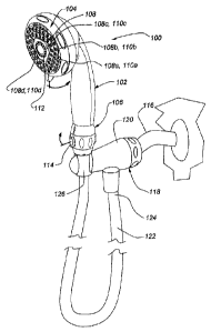
[0009] Fig. 1 is a perspective view of a handheld showerhead joined to a
fluid supply
pipe via a bracket and a handheld showerhead fluid conduit.
[0010] Fig. 2 is a front elevation view of the handheld showerhead of Fig.
1.
[0011] Fig. 3 is a cross-section view of the handheld showerhead of Fig. 1,
viewed along
line 3-3 in Fig. 2, where the showerhead engine is in a first position
relative to the handheld
showerhead housing.
[0012] Fig. 4 is an enlarged cross-section view of Fig. 3, showing a
portion of the
handheld showerhead of Fig. 1.
[0013] Fig. 5 is a cross-section view of a portion of the handheld
showerhead of Fig. 1,
viewed along line 5-5 in Fig. 4.
3
CA 02833476 2013-11-12
[0014] Fig. 6 is a top view of a flow control device for the handheld
showerhead of Fig. 1.
[0015] Fig. 6a is a cross-section view of the flow control device of Fig.
6, viewed along
line 6A-6A in Fig. 6, showing a flow control ring in a first position relative
to a flow control
housing.
[0016] Fig 6b is a cross-section view of the flow control device of Fig.
6, viewed along
line 6B-6B in Fig. 6, showing the flow control ring in a first position
relative to the flow control
housing
[0017] Fig. 7 is a bottom plan view of the flow control device of Fig. 6,
with a flow
restrictor, a filter screen, and a flow restrictor fastener not shown for
clarity.
[0018] Fig. 8 is an exploded perspective view of the flow control device
of Fig. 6.
[0019] Fig. 9 is a perspective view of a flow control housing for the flow
control device of
Fig. 6.
[0020] Fig. 10 is another perspective view of the flow control housing of
Fig. 9.
[0021] Fig. 11 is a perspective view of a flow control ring for the flow
control device of
Fig. 6.
[0022] Fig. 12 is another perspective view of the flow control ring of
Fig. 11.
100231 Fig. 13 is a front elevation view of a portion the handheld
showerhead of Fig 1,
showing the showerhead engine moved to a second position relative to the
handheld showerhead
housing.
[0024] Fig. 14 is a front elevation view of a portion the handheld
showerhead of Fig 1,
showing the showerhead engine moved to a third position relative to the
handheld showerhead
housing.
[0025] Fig. 15 is a front elevation view of a portion the handheld
showerhead of Fig 1,
showing the showerhead engine moved to a fourth position relative to the
handheld showerhead
housing.
[0026] Fig. 16 is a front elevation view of a portion the handheld
showerhead of Fig 1,
showing the showerhead engine moved to a fifth position relative to the
handheld showerhead
housing.
4
CA 02833476 2013-11-12
[0027] Fig. 17 is a cross-section view of a portion of the handheld
showerhead of Fig. 1,
viewed along line 17-17 in Fig. 2.
[0028] Fig. 18 is a cross-section view of a portion of the handheld
showerhead of Fig. 1,
viewed along line 18-18 in Fig. 13.
[0029] Fig. 19 is a cross-section view of a portion of the handheld
showerhead of Fig. 1,
viewed along line 19-19 in Fig. 14.
[0030] Fig. 20 is a cross-section view of a portion of the handheld
showerhead of Fig. 1,
viewed along line 20-20 in Fig. 15.
[0031] Fig. 21 is a cross-section view of a portion of the handheld
showerhead of Fig. 1,
viewed along line 21-21 in Fig. 16.
[0032] Fig. 22 is a cross-section view of the handheld showerhead of Fig.
1, viewed along
line 22-22 in Fig. 17.
[0033] Fig. 23 is a cross-section view of the handheld showerhead of Fig.
1, viewed along
line 23-23 in Fig. 17.
[0034] Fig. 24 is a cross-section view of the handheld showerhead of Fig.
1, viewed along
line 24-24 in Fig. 17.
[0035] Fig. 25 is a cross-section view of the handheld showerhead of Fig.
1, viewed along
line 25-25 in Fig. 17.
[0036] Fig. 26 is an exploded perspective view of the handheld showerhead
of Fig 1.
[0037] Fig. 27 is another exploded perspeetive view of the handheld
showerhead of Fig 1.
[0038] Fig. 28 is a perspective view of an embodiment of a wall mounted
showerhead
joined to a fluid supply line.
[0039] Fig. 29 is a cross-section view of the wall mounted showerhead of
Fig. 28, viewed
along line 29-29 in Fig. 28.
[0040] Fig. 30 is an exploded perspective view of a connection member
assembly for the
wall mounted showerhead of Fig. 28.
CA 02833476 2013-11-12
100411 Fig. 31 is a perspective view ofa second embodiment of a wall
mounted
showerhead joined to a fluid supply line.
[0042) Fig. 32 is a cross-section view of the wall mounted showerhead of
Fig. 31, viewed
along line 32-32 in Fig. 31.
[0043] Fig. 33 is a plan view of an upstream side of a nozzle member for
the wall
mounted showerhead of Fig. 31.
[0044) Fig. 34 is a plan view of a downstream side of the nozzle member of
Fig. 33.
[0045] Fig. 35 is a plan view of a upstream side of a face member for the
wall mounted
showerhead of Fig. 31.
DESCRIPTION OF THE INVENTION
[0046] Described herein are various embodiments of showerheads and
showerhead
assemblies employing flow rates less than 2.5 gallons per minute ("GPM").
These showerheads
and showerhead assemblies use flow regulators to supply flow rates less than
the 2.5 GPM flow
rate used in conventional showerhead. To accommodate these lower flow rates,
the fluid
passages within the showerhead and thc fluid outlets that deliver fluid from
the showerhead are
configured and/or sized to increase fluid exit velocity compared to a
conventional 2.5 GPM
showerhead by minimizing fluid pressure drop or energy loss through the
showerhead and/or by
enhancing the pressure drop at the fluid outlet. The showerheads may further
include large water
passages to allow unrestricted flow to the exit nozzles, thus allowing the
maximum available
pressure drop at the fluid outlets to provide appropriate fluid exit
velocities for the lower flow
rate. Some embodiments of the showerhead may include a user operated flow
device for further
adjusting the flow of liquid from the showerhead.
10047] The showerheads and showerhead assemblies of the embodiments shown
the
figures may be used with a handheld showerhead, a wall mounted showerhead or
any other
appropriate showerhead. The handheld and wall mounted showerheads may be
fluidly joined to
a water supply line. The water supply line may be controlled with a water
control valve or knob.
[0048] Figs. 1-27 depict an embodiment of a low flow handheld showerhead
100. Fig. 1
6
CA 02833476 2016-06-20
shows a perspective view of the handheld showerhead 100, and Fig. 2 shows a
front view of the
handheld showerhead 100 shown in Fig. 1. The handheld showerhead 100 may
include a
handheld showerhead housing 102, a showerhead engine 104, and a flow control
device 106.
The showerhead engine 104 may be joined to an upper end portion of the
handheld showerhead
housing 102. The showerhead engine 104 may include one or more fluid outlets
108 that deliver
a fluid, such as water, from the handheld showerhead 100. The fluid outlets
108 may take the
form of nozzles, openings or holes, or any other suitable structure for
delivering fluid from the
handheld showerhead 100.
[0049] The fluid outlets 108 may be configured into one or more groups 110a-
d. Each
such group 110a-d may be associated with one or more operation modes for the
handheld
showerhead 100. When a fluid outlet group 110a-d is associated with a
particular mode during
operation of the handheld showerhead 100, fluid is delivered from one or more
of the fluid
outlets 108a-d in the group when the associated mode is selected, and fluid is
not delivered from
these fluid outlets 108a-d when the associated mode is not selected. At least
a portion of the
showerhead engine 104 may be selectively moveable relative to the handheld
showerhead
housing 102 to change an operation mode of the handheld showerhead 100.
100501 The fluid outlets 108 may be configured into four groups 110a-d. If
desired. the fluid outlets 108 may be configured into more or less than four
groups. Each
of the four fluid outlet groups 110a-d may be associated with a distinct spray
or operation
mode. The first fluid outlet group l 10a may include an outer row of three
generally
arcuate lines of five fluid outlets 108a (ee., nozzles), which may be
associated with a fan
spray mode. The second fluid outlet group 110b may include two rows of fluid
outlets 108b (e.g,. nozzles) adjacent to but radially inward from the outer
row of fluid
outlets 110a. The second fluid outlet group I !fib may be associated with a
full body spray
mode. The third fluid outlet group 110c may include three fluid outlets 108c
(e.g.
nozzles) positioned adjacent to but radially inward from the second group of
fluid
outlets 110b. This third group of fluid outlets I08e may be associated with a
mist spray
inode. The fourth fluid outlet group 110d may include the generally circular
row of fluid
outlets 108d (e.g. nozzles) positioned within the central area of the
showerhead face
member 112. The fourth group of fluid outlets 110d may be associated with a
pulsating
spray mode. Although the modes are described with a certain particularity, any
fluid
outlet group may- be associated with any type of showerhead mode or spray,
including but
not limited to a drenching spray, a
7
CA 02833476 2013-11-12
champagne spray, a fun spray, a mist spray, a message spray and so on.
[0051] The flow control device 106 may be joined to a lower end portion of
the
handheld showerhead housing 102. At least a portion of the flow control device
106 may be
selectively moved relative to the handheld showerhead housing 102 to
selectively change the
flow rate of fluid delivered to the handheld showerhead 100. The flow control
device 106 may
include a knob 114 or other user engagement feature that a user may grasp to
move the at least a
portion of the flow control device 106 relative to the handheld showerhead
housing 102.
[0052] The handheld showerhead 100 may be mechanically and fluidly joined
to a fluid
supply line or source by a bracket 118 or other suitable fitting. The bracket
118 may be any
commercially available or otherwise known handheld showerhead attachment
device or bracket.
One embodiment of the bracket 118 will be briefly described below.
[0053] The bracket 118 may include a bracket housing 120 including a
receptor for
joining the handheld showerhead 100 to the bracket 118 and for retaining the
handheld
showerhead 100 in a rest position. The bracket 118 may be joined to the fluid
pipe 116 that
supplies fluid to the handheld showerhead 100. The bracket 118 may further be
attached to a
handheld showerhead conduit 122, such as a flexible hose, at a first end, or
upstream, portion
124, of the showerhead conduit 122. A second end, or downstream, portion 126
of the handheld
showerhead conduit 122 may be joined to the handheld showerhead 100, thus
providing fluid
communication between the bracket 118 and the handheld showerhead 100. The
handheld
showerhead conduit 122 may extend a length suitable for use by the user as a
hand operated
showerhead and may be made of commercially available material, such as a
plastic, a composite
or the like.
[0054] Fig. 3 depicts a cross-section view of the handheld showerhead 100
shown in Figs. 1 and
2. Fig. 4 depicts an enlarged cross-section view of a portion of the handheld
showerhead 100.
Fig. 5 depicts another cross-section view of a portion of the handheld
showerhead 100, view
along line 5-5 in Fig. 4. Fig. 6 depicts a top view of the flow control
8
CA 02833476 2013-11-12
device 106, and Fig. 7 depicts a bottom plan view of the flow control device
106 with a flow
restrictor, filter screen, and flow control fastener not shown. Fig. 8 depicts
an exploded
perspective view of the flow control device 106. Fig. 9 depicts a perspective
view of a flow
control housing of the flow control device 106. Fig. 10 depicts another
perspective view of the
flow control housing shown in Fig. 9. Fig. 11 depicts a perspective view of
flow control ring of
the flow control device 106. Fig. 12 depicts another perspective view of the
flow control ring
shown in Fig. 11.
[00551 With reference to Figs. 3 and 4, the water pipe or other fluid
supply conduit 116
may include a threaded end for engagement with a pivot ball 128 pivotally
joined to the bracket
118. The water pipe 116 and pivot ball 128 may each include generally co-
axially aligned fluid
passages for delivering water or other fluid from the fluid source to the
bracket 118. The bracket
118 may include a bracket body 134 defining a fluid passage or chamber 136 in
fluid
conununication with the pivot ball fluid passage 132. A generally annular or
other suitably
shaped bracket sidewall 138 may extend from the bracket body 134. The bracket
sidewall 138
may define a bracket sidewall fluid passage 140 in fluid communication with
the bracket fluid
passage 136_
[0056] An end portion of the bracket sidewall 138 may be externally
threaded to engage
with internal threads formed on the first or upstream end portion 124 of the
handheld
showerhead conduit 12/ In other embodiments, the bracket sidewall 138 may be
internally
threaded and the upstream end portion 124 of the handheld showerhead conduit
122 may be
externally threaded. Engagement of the bracket sidewall threads and the
upstream handheld
showerhead conduit threads joins the handheld showerhead conduit 122 to the
bracket 118.
Although shown as threadedly joined together, the bracket 118 and handheld
showerhead
conduit 122 may be joined by any known connection method, including, but not
limited to,
press-fit, mechanical fasteners, welds, and so on.
[00571 The handheld showerhead conduit 122 may include a handheld
showerhead
conduit body 142 defining a handheld showerhead conduit fluid passage 144. The
handheld
showerhead conduit fluid passage 144 may generally co-axially align with the
bracket sidewall
fluid passage 140 when the handheld showerhead conduit 122 is joined to the
bracket 118. Thus,
fluid may flow from the water pipe fluid passage 130 to the handheld
showerhead conduit fluid
9
CA 02833476 2013-11-12
passage 144 via the pivot ball fluid passage 132, the bracket fluid passage
136, and the bracket
sidewall fluid passage 140.
[00581 With reference to Figs. 4-12, the flow control device 106 may
include a flow
control housing 150, a flow control ring 152, and a flow control fastener 154.
A lower end
portion of the flow control housing 150 may be externally threaded to engage
with internal
threads formed on the second ot downstream end portion 126 of the handheld
showerhead
conduit 122. In other embodiments, the lower end portion of the flow control
housing 150 may
be internally threaded and the downstream end portion 126 of the handheld
showerhead conduit
122 may be externally threaded. Engagement of the lower end portion threads of
the flow
control housing 150 and the downstrsam handheld showerhead conduit threads
joins the flow
control device 106 to the handheld showerhead conduit 122. Although shown as
threadedly
joined together, the flow control device 106 and handheld showerhead conduit
122 may be
joined by any known connection method, including, but not limited to, press-
fit, mechanical
fasteners, welds, and so on.
[0059] The upper end portion of the flow control housing 150 may be
internally threaded
to engage with external threads formed on an end of the handheld showerhead
housing 102. In
other embodiments, the upper end portion of the flow control housing 150 may
be externally
threaded and the end portion of the handheld showerhead housing 102 may be
internally
threaded. Engagesnent of the upper end portion threads of the flow control
housing 150 and the
handheld showerhead housing threads joins the flow control device 106 to the
handheld
showerhead housing 102. Although shown as threadedly joined together, the flow
control device
106 and handheld showerhead homing 102 may be joined by any known connection
method,
including, but not limited to, press-fit, mechanical fasteners, welds, and so
on.
[00601 The flow control housing 150 defines a lower flow control fluid
chamber 156 in
fluid communication with the handheld showerhead conduit fluid passage 144
when the flow
control housing 150 and the handheld showerhead conduit 122 are joined. The
flow control
housing 150 also defines an upper flow control fluid chamber 158 in fluid
communication with a
fluid passage 160 defined by the handheld showerhead housing 102. As described
in more detail
below, the lower and upper fluid control chambers 156, 158 are in fluid
communication, thus
allowing fluid to flow from the handheld showerhead conduit fluid passage 144
to the handheld
CA 02833476 2013-11-12
showerhead housing fluid passage 160 via these chambers 156, 158. Further, as
described in
more detail below, the flow rate between the lower and upper fluid control
chambers 156, 158
may be changed by selectively Mating the flow control ring 152 around the flow
control housing
150.
[0061] As the flow rate between the lower and upper fluid control chambers
156, 158 is
changed, the flow rate delivered to die fluid outlets 108 in the handheld
showerhead 100 from
the water source via the bracket 118 and the handheld showerhead conduit 122
changes.
Accordingly, a user may selectively increase or decrease the flow rate of
fluid from the fluid
outlets 108 in the handheld showerhead 100 by selective rotation of the flow
control ring 152
relative to the flow control housing 150. Further, in some embodiments the
flow control device
106 may allow a user to pause flow for any of the spray operation modes of the
handheld
showerhead 100, by selective rotation of the flow control ring 152 relative to
the flow control
housing 150.
[0062] The lower flow control fluid chamber 156 may be inwardly stepped to
form a
lower flow control fluid chamber ledge 162 for a flow restrictor 164 to
engage. Positioning the
flow restrictor 164 al the flow control device 106 rather than within the
bracket 118 as
conventionally done in handheld showerheads reduces the fluid pressure drop
from the flow
restrictor 164 to the fluid outlets 108 in the handheld showerhead 100
compared to a
conventional handheld showerhead with the flow restrictor positioned within or
proximate the
bracket 118.
[0063] The flow restrictor 164 may take the form of a generally cylindrical
or other
suitably shaped component that includes one or more apertures or other
openings to limit the
flow of water through the flow restrictor 164. The flow restrictor 164 may
limit the flow rate of
fluid paging through it to approximately 1.5 Gallons Per Minute ("GPM") or
less, thus resulting
in a fluid flow rate delivered from the fluid outlets 108 of approximately 1.5
GPM or less.
Conventional handheld and other showerheads employ flow restrictors that
permit flow rates
through their fluid outlets of up to approximately 2.5 GPM. Although a
specific flow rating is
disclosed herein, the flow restrictor 164 may employ any flow rating below the
conventional 2.5
GPM flow rate.
[0064] A filter screen 166 may be positioned on the upstream side of the
flow restrictor
11
CA 02833476 2013-11-12
164. The filter screen 166 may be formed from a wire or other type of mesh
that defines one or
more apertures to filter particles contained within fluid flowing through the
flow restrictor 164.
The filter screen apertures may be smaller than the flow restrictor apertures,
thus reducing the
potential for the apertures in the flow restrictor 164 to become clogged. A
flow restrictor fastener
168 may be positioned upstream of the filter screen 166. The flow restrictor
fastener 168 may
include a generally annular flow restrictor fastener body 170 defining a hole
for allowing fluid to
flow through the flow restrictor fastener 168. One or more flow restrictor
fastener tabs 172 may
extend radially outward from the flow restrictor fastener body 170. The flow
restrictor fastener
tabs 172 may be at least somewhat flexible and may be engaged with the flow
control housing
150 to join the flow restrictor fastener 168 to the flow control housing 150.
The flow restrictor
164 and the filter screen 166 may be sandwiched between the flow control
housing 150 and flow
restrictor fastener 168, thus retaining the flow restrictor 164 and the filter
screen 166 within the
lower flow control fluid chamber 156 of the flow control housing 150.
[0065] As discussed above, the flow rate to the fluid outlets 108 in the
handheld
showerhead 100 may be further controlled using the flow control device 106.
More particularly,
the flow control ring 152 in combination with the flow control housing 150 may
be used to
change the flow rate to the fluid outlets 108 of the handheld showerhead 100.
To change the flow
rate, fluid communication between the lower and upper flow control fluid
chambers 156, 158 may
be selectively controlled by a flow control fluid chamber 174 defined by an
inner surface of the
flow control ring 152 and an outer surface of the flow control housing 150.
Fluid communication
between the flow control fluid chamber 174 and the lower flow control fluid
chamber 156 may be
provided by a lower fluid chamber outlet 176 defined in the flow control
housing 150. Fluid
communication between the flow control fluid chamber 174 and the upper flow
control fluid
chamber 158 may be provided by an upper fluid chamber inlet 178 defined in the
flow control
housing 150.
[0066] As perhaps best shown in Figs. 8 and 9, the lower fluid chamber
outlet 176 and the
upper fluid chamber inlet 178 may be positioned proximate to each other on the
flow control
housing 150. The lower fluid chamber outlet 176 may be defined by a single,
generally
rectangular or other suitably shaped aperture. The upper fluid chamber inlet
178 may be defined
by two generally rectangular or other suitably shaped apertures. More than a
single aperture may
be used for the lower fluid chamber outlet 176, and more or less than two
apertures may be use
12
CA 02833476 2016-06-20
100671 The portion of the flow control fluid chamber 174 in fluid
communication with the lower and upper fluid control chambers 156, 158 may be
selectively changed by rotating the flow control ring 152 relative to the flow
control
housing 150. Specifically, a flow control ring recess 180 (see Figs. 6a and
11) may be
defined in the flow control ring 150. The flow control ring recess 180 and the
outer
surface of the flow control housing 150 define the flow control fluid chamber
174. As the
flow control ring 152 is rotated about the flow control housing 150, the
position of the flow
control ring recess 180, and thus the position of the flow control fluid
chamber 174,
changes relative to the flow control housing 150. The flow control ring 152
may be
joined to the flow control housing 150 such that the flow control recess I 80
may be moved
from a first position over the lower fluid chamber outlet 176 and the upper
fluid chamber
inlet 178 (see Fig. 6A) to a second position in which it is not over at least
one of the lower
fluid chamber outlet 176 and the upper fluid chamber inlet 178 (see Fig. 6B).
In some
embodiments, as shown, for example. in Fig 6B, the flow control recess 180 may
be over
neither the lower fluid chamber outlet 176 nor the upper fluid chamber inlet
178 in the
second position.
100681 In the first position, as shown, for example, in Fig. 6A, the flow
control
recess 180, and thus the flow control fluid chamber 174, is in fluid
communication with
both the lower fluid chamber outlet 176 and the upper fluid chamber inlet 178.
In the
second position, as shown, for example, in Fig. 6B, the flow control recess
180, and thus
the flow control fluid chamber 174, is not in fluid communication with at
least one of the
lower fluid chamber outlet 176 or the upper fluid chamber inlet 178. Further,
in the first
position, the flow rate from the lower flow control fluid chamber 156 to the
upper flow
control fluid chamber 158 is at a maximum since the portion of the flow
control recess 180,
and this the portion of the flow control fluid chamber 174, in fluid
communication with
both the upper fluid chamber inlet I 78 and the lower fluid chamber outlet 176
is at a
maximum. As the flow control recess is moved from the first position to the
second
position, the flow rate from the lower flow control fluid chamber 156 to the
upper flow
control fluid chamber 158 decreases since the portion of the fluid control
recess 180, and
thus the portion of the fluid control chamber 174, in fluid conununication
with either the
lower fluid chamber outlet 176 or the upper fluid chamber inlet 178 decreases.
f00691 To ensure at least a minimal level of fluid communication between
the lower and
CA 02833476 2016-06-20
upper flow control fluid chambers 156, 158 regardless of the position of the
flow control recess
180 relative to the lower fluid chamber outlet 176 and upper fluid chamber
inlet 178, a flow
control notch 182 may be defined in the flow control housing 150. The flow
control notch 182
may extend between the lower fluid chamber outlet 176 and the upper fluid
chamber inlet 178,
thus providing constant fluid communication between this outlet 176 and inlet
178. Such constant
fluid communication prevents a deadhead from being formed in the flow control
device 106 when
the flow control recess 180 is not in fluid communication with either, or
both, of the upper fluid
chamber inlet 178 and the lower fluid chamber outlet 176.
[0070] To limit the fluid flow to the flow control notch 182 when the flow
control ring
152 is positioned at the second location relative to the flow control housing
150 as shown in Fig.
6B, the flow control ring 152 may include a flow ring seal recess 186 for
receiving a flow ring
seal 188. The flow ring seal 188 may extend at least slightly beyond the seal
ring recess 186 so
that it is at least slight compressed against thc flow control housing 150.
Such compression biases
the flow ring seal 188 against the flow control housing 150, thus preventing
fluid leakage between
the flow control housing 150 and portions of the flow ring seal 188 in contact
with the flow
control housing 150.
[0071] When the flow control ring 152 is in the second position relative to
the flow
control housing 150, the flow ring seal 188 covers the lower fluid chamber
outlet 176 and the
upper fluid chamber inlet 178. Further, the flow ring seal 188 is biased into
contact with the
portion of the outer surface of the flow control housing 150 that encompasses
the lower fluid
chamber outlet 176 and the upper fluid chamber inlet 178. This contact
prevents fluid movement
between the lower fluid chamber outlet 176 and the upper fluid chamber inlet
178 along the
engagement surfaces of the flow control housing 150 and the flow ring seal
188. Thus, fluid flow
between the lower fluid chamber outlet 176 and the upper fluid chamber inlet
178 is limited to the
flow control notch 182.
[0072] The flow ring seal 188 may be sized to at least cover the lower
fluid chamber outlet 176
and the upper fluid chamber inlet 178 when the flow control ring 152 is
positioned at the second location
relative to the flow control housing 150. The flow ring seal 188 may be
generally rectangular or any other
suitable shape. The flow ring seal 188 may be made from rubber or any other
suitable seal material. The
flow ring seal recess 186 may be positioned
14
CA 02833476 2016-06-20
adjacent to the flow control ring recess 180. The flow ring
seal recess 186 may be sized to receive the flow ring seal 188 with the depth
of the flow
ring seal recess 186 at least slightly less than the thickness of the flow
ring seal 188. In
some embodiments, the flow ring seal recess 186 may be sized to snug tightly
receive the
flow ring seal 188.
100731 The upper flow control fluid chamber 158 may be in fluid
communication with the
fluid outlets 108 of the showerhead. Thus, as the flow rate between the lower
and upper flow
control fluid chambers 156, 158 of the flow control housing 150 is changed by
rotating the flow
control ring 152 relative to the flow control housing 150, the flow rate of
water to the showerhead
fluid outlets 108 also changes. In other words, the flow rate to the fluid
outlets 108 may be
further reduced from the maximum flow rate permitted by the flow restrictor
164 by reducing the
portion of the flow control fluid chamber 174 in fluid communication with
either, or both, of the
upper fluid chamber inlet 178 and lower fluid chamber outlet 176 via rotation
of the flow control
ring 152 around the flow control housing 150 Further, the showerhead may be
placed in a pause
mode by rotating the flow control ring 152 to a position relative to the flow
control housing 150
where fluid communication between the upper fluid chamber inlet 178 and lower
fluid chamber
outlet 176 is provided by just the flow control notch 182.
100741 Indicia or other markings may be defined in, or placed on, the flow
control device
106 to provide an indication to a user about the selected flow rate using the
flow control device
106. For example, water drop shaped recesses 184 may be defined in the flow
control housing
150. Continuing with the example, three such recesses 184 may be defined in
the flow control
housing 150 that align with the flow control knob 114 when the flow control
ring 152 is
positioned at the first position relative to the flow control housing 150,
thus indicating to a user
that the maximum flow rate is selected. Still continuing with the example, one
such recess 184
may be defined in the flow control housing 150 that aligns with the flow
control knob 114 when
the flow control ring 152 is positioned at the second position relative to the
flow control housing
150, thus indicating to a user that the minimum or pause flow rate is
selected. The foregoing
example is merely illustrative and is not intended to require or imply any
particular indicia or
marking for providing an indication to the user of the relative selected flow
rate. Further, in some
embodiments, the indicia or other markings may be omitted. In yet other
embodiments, numbers
or other symbols may be used for the indicia.
CA 02833476 2013-11-12
(00751 The flow control device 106 may further include a rotation
limiting system to
limit the rotation of the flow control ring 152 relative to the flow control
housing 150. The
rotation limiting system may take the form of a flow control stop 200 received
within a flow
control stop groove 202. The flow control stop 200 may extend from the inner
surface of the
flow control ring 152. The flow control stop move 202 may be defined in the
outer surface of
the flow control housing 150. Engagement of the flow control stop 200 with an
end of the flow
= control stop groove 202, as shown, for example, in Figs. 6A and 6B,
limits further rotation of the
flow control ring 152 relative to the flow control housing 150 in the
direction of eng,agement.
The flow control stop groove 202 may be sized to permit rotation of the flow
control ring 152
relative to the flow control housing 150 from the first position (i.e., the
maximum flow rate
position) to the second position (i.e., the minimum flow rate or pause
position), and vice versa.
[00761 In some embodiments, the flow control stop 200 may extend
from the outer
surface of the flow control housing 150, and the flow control stop move 202
may be defined in
the inner surface of the flow control ring 152. Further, any other known
system for limiting
relative rotation of one member about another member may be used to limit the
relative rotation
of the flow control ring 152 relative to the flow control housing 150. Yet
further, in some
embodiments, the rotation limiting system may be omitted.
(0077j An. upper seal element 204 and a lower seal element 206 may
be positioned
respectively above and below the flow control fluid chamber 174. Each seal
element 204, 206
may be positioned within a corresponding circumferential groove defined in the
flow control
housing 150. The upper and lower seal elements 204, 206 limit fluid leakage
from the flow
control fluid chamber 174 between the joint formed between the inner surface
of the flow contro/
ring 152 and the outer surface of the flow control housing 150. The upper and
lower seal
= elements 204, 206 may take the form of cup seals or any other known seal,
including, but not
limited to, 0-rings or the like. The upper and lower seal elements 204, 206
may be formed from
rubber or other elastomeric material, or any other suitable material.
[0078) The flow control fastener 154 may include an internally
threaded surface for
engagement with the external threads formed on the lower end portion of the
flow control
housing 150. Engagement of the flow control fasner tltreads with the threads
on the lower end
portion of the flow control housing 150 joins the flow control fastener to the
flow control
16
CA 02833476 2016-06-20
housing. Although shown as threadediy joined together,
the flow control fastener 154 and fiow control housing 160 may be joined by
any known connection
method, including, but not limited to, press-fit, mechanical fasteners, welds,
and so on.
[0079] The flow control ring 152 may include a generally annular or other
suitably shaped
flow control ring body 208 that defines a flow control ring aperture for
receiving a portion of the
flow control housing 150. As discussed above, the flow control ring 152 may be
selectively
rotated around the flow control housing 150. Such rotation may be facilitated
by the flow control
knob 114 or other user grasping element. The flow control knob 114 or user
grasping element
may extend from an outer surface of the flow control ring body 208. The flow
control knob 114
may be generally elliptical or any other suitable shape and may be sized to be
grasped by a user.
The flow control ring 152 may be positioned between the upper end portion of
the flow control
housing 150 and the flow control fastener 154, thus rotatably joining the flow
control ring 152 to
the flow control housing 150.
100801 With reference to Fig. 3, the handheld showerhead housing 102 may
include a
handle portion 220 and a showerhead portion 222. As discussed above, a lower
end segment of
the handle portion 220 may be threaded for engagement with threads formed on
the flow control
housing 150. Engagement of the handle portion threads and the flow control
housing threads
joins the handheld showerhead housing 102 to the flow control device 106. In
some
embodiments, the flow control device 106 may be omitted, and the handheld
showerhead housing
102 may be joined, using a threaded engagement or any other suitable
connection method, to the
handheld showerhead conduit 122.
[0081] A handle seal member 224 may be positioned between an end of the
handle
portion 220 and the flow control housing 150. The handle seal member 224 may
be an 0-ring or
any other suitable sealing element. The handle seal member 224 may limit or
prevent fluid flow
between the joined segments of the handle portion 220 and the flow control
housing 150. The
handle seal member 224 may be made of rubber or any other suitable seal
material.
[0082] The handle portion 220 may include an outer gripping surface for a
user to hold the
handheld showerhead 100. An inner surface of the handle portion 220 may define
a handle fluid
passage 226 or channel. The handle portion 220 may be generally elongated and
may be
ergonomically designed for ease of gripping and use. The handle fluid passage
226 or channel
17
CA 02833476 2013-11-12
may extend from a lower end segment of the handle portion 220 to the
showerhead portion 222.
As a non-limiting example, in conventional 2.5 GPM handheld showerhead
devices, the handle
fluid passage has a diameter of approximately 0.23 inch. The handle fluid
passageway of a
handheld showerhead is sized to be larger than the handle fluid passage for a
conventional25
GPM handheld showerhead.
[0083] In particular, the handle fluid passage 226 of the handheld
showerhead 100 may
have a diameter that is approximately at least fifty percent larger than the
diameter of a
conventional 2.5 GPM handle fluid passage. In some embodiments, the handle
fluid passage 226
of the handheld showerhead 100 may have a diameter of approximately two
hundred to three
hundred percent larger than a conventional 2.5 GPM handle fluid passage.
Because of this larger
diameter for the handle fluid passage 226, fluid (e.g., water) flowing through
the handle portion
220 is less restricted than in conventional handheld showerheads.
[0084] Fig. 2 shows the showerhead engine 104 in a lust position relative
to the handheld
showerhead housing 102. Figs. 13-16 show the showerhead engine 104 moved to
other positions
relative to the handheld showerhead housing 102. Figs. 17-21 show cross-
section views of the
showerhead engine 104 for the various positions of the showerhead engine 104
relative the
handheld showerhead housing 102 as shown in Figs. 2 and 13-16 respectively.
Figs. 26 and 27
show exploded perspective views of the showerhead engine 104.
[0085] With reference to Figs. 17-21, the showerhead engine 104 may include
a flow
director or back member 250, a flow channel or intermediate member 252, one or
more nozzle
members 254, a turbine or front member 256, and the face member 112. The
handheld
showerhead 100 may further include a stationary member 258. The stationary
member 258 may
defule a stationary member fluid chamber 260 in fluid communication with the
handle fluid
passage 226 and a stationary member fluid outlet 262 in fluid communication
with the stationary
member fluid chamber 260.
100861 The flow director member 250, the flow channel member 252 and the
turbine
member 256 may define one or more fluid chamber passages in fluid
communication with the
various groups of nozzles and other fluid outlets 108 defined in the nozzle
member 254 and/or
the turbine member 256. Further, the flow director member 250, the flow
channel member 252,
the nozzle member 254, the turbine member 256, and the face member 112 may be
joined or
18
CA 02833476 2016-06-20
otherwise assembled
to rotate in unison relative to the stationary member 258. Such rotation
changes which fluid chambers or
passages are in fluid communication with a stationary member fluid outlet 262,
thus changing which fluid
outlet group or groups 110a-110d are in fluid communication with the
stationary member fluid outlet 262.
Thus, a user may select a spray or operation mode by selectively rotating the
showerhead engine 104
relative to the stationary member 258.
[0087] More particularly, Figs. 2 and 17 show the showerhead engine 104 in
a first
position relative to the stationary member 258. In this first position, the
stationary member fluid
outlet 262 is in fluid communication with the group of fluid outlets 110 b for
the full body spray.
Fluid communication between the full body spray fluid outlets 108 b and the
stationary member
fluid outlet 262 is provided via an upper HI body fluid aperture 264 defined
in the flow director
member 250, an upper full body fluid chamber 266 defined by the flow director
member 250 and
the flow channel member 252, one or more lower full body fluid apertures 268
defined in the flow
channel member, and a lower full body fluid chamber 270 defined by the flow
channel member
252 and the turbine member 256.
100881 Figs. 13 and 18 show the showerhead engine 104 in a second position
relative to
the stationary member 258. In this second position, the stationary member
fluid outlet 262 is in
fluid communication with the first fluid outlet group 110a for the fan spray.
Fluid communication
between the fan spray fluid outlets 108a and the stationary member fluid
outlet 262 is provided
via an upper fan fluid aperture 272 defined in the flow director member 250,
an upper fan fluid
chamber 274 defined by the flow director member 250 and the flow channel
member252, one or
more lower fan fluid apertures 276 defined in the flow channel member 252, and
one or more
lower fan fluid chambers 278 defined by the flow channel member 252 and the
turbine member
256.
[0089] Figs. 14 and 19 show the showerhead engine 104 in a third position
relative to the
stationary member 258. In this third position, the stationary member fluid
outlet 262 is in fluid
communication with the group of fluid outlets 110d for the pulsating spray.
Fluid communication
between the pulsating spray fluid outlets 108d and the stationary member fluid
outlet 262 is
provided via an upper pulsating fluid aperture 280 defined in the flow
director member 250, an
upper pulsating fluid chamber 282 defined by the flow director member 250 and
19
CA 02833476 2013-11-12
the flow channel member 252, one or more lower pulsating fluid apertures 284
defined in the
flow channel member 252, and a pulsating fluid chamber 286 defined by the flow
channel
member 252 and the turbine member 256.
[0090] Figs. 15 and 20 show the showerhead engine 104 in a fourth position
relative to
the stationary member 258. In this fourth position, the stationary member
fluid outlet 262 is in
fluid communication with the group of fluid outlets 110c for the mis' t spray.
Fluid
communication between the mist spray fluid outlets 108c and the stationary
member fluid outlet
262 is provided via an upper mist fluid aperture 288 defined in the flow
director member 250, an
upper mist fluid chamber 290 defined by the flow director member 250 and the
flow channel
member 252, one or more lower mist fluid apertures 292 defined in the flow
channel member
252, and one or more low mist fluid chambers 294 defined by the flow channel
member 252 and
the turbine member 256.
100911 Figs. 16 and 21 show the showerhead engine 104 in a fifth position
relative to the
stationary member 258. Like the fourth position, the stationary member fluid
outlet 262 is in
fluid communication with the group of fluid outlets 110c for the mist spray.
However, in this
fifth position, the handheld showerhead operates in a pause mode because the
upper pause fluid
aperture 296 in fluid communication with the stationary member fluid outlet
262 is much smaller
than the upper mist fluid apeatre 288 for the fourth position. Thus, the flow
rate delivered from
the mist spray fluid outlets 108c is very low when the showerhead engine is in
this fifth position.
Other than the smaller upper fluid aperture 296, fluid communication between
the mist fluid
outlets 108c and the stationary member fluid outlet 262 is the same as for the
fourth position of
the showerhead engine 104 relative to the stationary member 258.
100921 The feel for a user from showerhead water that contacts the user is
a function of
the velocity and flow rate of the water that exits the showerhead. Generally,
as the flow rate
decreases, the exit velocity of the fluid needs to be increased to maintain an
aesthetically
pleasing shower experience for a user. To increase the exit velocity, the
pressure drop of the
fluid within a showerhead should occur at the fluid outlets rather than
through the showerhead
engine. In other words, it is preferable to maintain fluid pressure as high as
possible until the
fluid exits the handheld showerhead at the fluid outlet so as to create the
maximum pressure drop
when the fluid exits the handheld showerhead.
CA 02833476 2013-11-12
[00931 The number of turns the fluid makes within the showerhead
engine, or distance
-
the fluid must travel to pass through apertures in the various members forming
the showerhead
engine, before reaching the fluid outlets may be minimized in the showerhead
engine because
each turn or corner that the fluid encounters, or additional distance the
fluid must travel, leads to
a pressure drop. To further improve the fluid exit velocity from the
showerhead for the lower
flow rate, the ratio of the total area for each fluid chamber, passage or
aperture within the
showerhead engine may be at least five times the total area of the fluid
outlet openings associated
with the particular fluid chamber, passage or aperture. To yet further improve
the fluid exit
velocity of the handheld showerhead, the total area of the fluid outlet
openings for an outlet
group of the handheld showerhead may be configured to be between approximately
0.020 square
inches to approximately .040 square inches. This is generally less than the
total area of the fluid
outlets for a conventional 2.5 GPM showerhead, which typically range from
0.050 to 0.070
square inches.
(0094j Accordingly, the showerhead engine 104 for the handheld
showerhead 100 may
be configured to minimitP the number of turns encountered by water flowing in
the showerhead
engine 104, to decrease the pressure drop through the showerhead engine,
and/or to increase the
pressure drop at the fluid outlets. Additionally, the fluid chambers, passages
or apertures
throughout the handheld showerhead 100 may be widened and/or shaped to
increase or maintain
water volimae and pressure.
[00951 Figs. 22-25 show various cross-section views of the
showerhead engine. These
various figures show one possible way to form the various upper and lower
fluid chambers and
apertures in the showerhead engine 104 for each opaation mode to minimize the
number of
turns and/or distance the fluid must travel, and/or to form fluid chambers
and/or fluid apertures
with total areas that are at least five times the total area of the fluid
outlet openings associated
with the particular fluid chamber or aperture.
(0096] With reference to Figs. 22 and 23, the upper fan fluid
chamber 274 inay take the
form of a substantially annular space in planar cross-section that is defined
by first and second
aligned downstream flow director and upstream flow channel walls 298, 300,
302, 304 that
extend from the downstream side of flow director member 250 and the upstream
side of the flow
charm' member 252. The upper full body fluid chamber 266 may take the form of
a
21
CA 02833476 2013-11-12
substantially C-shaped space in planar cross-section, which is adjacent to but
radially inward of
the upper full body fluid chamber 266. The upper mist fluid chamber 290 may be
defined by
aligned third and fourth downstream flow director and upstream flow channel
walls 306, 310,
308, 312 that extend from the downstream side of flow director member 250 and
the upstream
side of the flow channel member 252. The upper pulsating fluid chamber 282 may
take the form
a generally pentagonal space in planar cross-section, which is adjacent to but
radially inward of
the upper mist fluid chamber 290. The upper pulsating fluid chamber 282 may be
defined by a
portion of the aligned second downstream flow director and upstream flow
channel walls 300,
304 and by aligned downstream flow director and upstream flow channel fourth
walls 310, 312
that extend from the downstream side of flow director member 250 and the
upstream side of the
flow channel member 252, respectively.
100971 The upper full body fluid aperture 264, the upper fan fluid
aperture 272, the upper
mist fluid aperture 288, and the upper pulsating fluid aperture 280 may each
be generally circular.
Three lower fan fluid apertures 276, eight lower full body fluid apertures
268, three lower mist
fluid apertures 292, and three lower pulsating fluid apertures 284 may be
defined in the flow
channel member 252. The lower fan fluid apertures 276 may be generally arcuate
and may be
spaced apart at approximately radially equal distances. The lower full body
fluid apertures 268
may be generally circular. The lower full body fluid apertures 268 may be
formed into two
groups of three lower full body fluid apertures 268 and one group of two lower
full body
apertures 268. Within each group, the lower full body fluid apertures 268 may
generally be
spaced apart at approximately radially equal distance. Further, each group of
lower full body
apertures 268 may be positioned within generally equally sized sectors on the
flow director
member 250.
[0098] The lower mist fluid apertures 292 may be generally rectangular and
may be
spaced apart at approximately radially equal distances. The lower pulsating
member fluid
apertures 284 may be generally elongated slots and may be spaced apart at
approximately
22
CA 02833476 2013-11-12
radially equal distances. The lower pulsating member apertures 284 may be
formed through the
flow channel member 252 at an angle relative to upper and lower surfaces of
the flow channel
member 252 to direct an angled fluid stream onto a ttubine positioned within
the lower pulsating
fluid chamber 286. Any of the apertures may be of various dimensions. While
specific apertures
are described herein for the upper and lower fan, full body, mist and
pulsating apertures, any
aperture suitable for the intended spray pattern would be acceptable. Further,
while specific
arrangements, shapes and numbers for these apertures are described herein,
various other
arrangements, shapes, or numbers may be used.
[00991 With reference to Figs. 24 and 25, the showerhead engine 104 may
include three
lower fan fluid chambers 278, three lower mist fluid chambers 294, a lower
pulsating fluid
chamber 286, and a lower full body fluid chamber 270. Each lower fan fluid
chamber 278 may
take the form of a substantially arcuate space. in planar cross-section, which
is defined by aligned
downstream flow channel and upstream turbine walls 314, 316 that extend from
the downstream
side of flow channel member 252 and the upstream side of the turbine member
256. Each lower
mist fluid chamber 294 may take the form of a substantially rectangular space
in planar cross-
section, which is defined by aligned downstream flow chtamel and upstream
turbine walls 318,
320 that extend from the downstream side of flow channel member 252 and the
upstream side of
the turbine member 256.
[001001 The lower pulsating fluid chamber 286 may take the form of a
generally circular
space in planar cross-section, which is defined by aligned downstream flow
channel and
upstream turbine walls 322, 324 that extend from the downstream side of flow
channel rnember
252 and the upstream side of the turbine member 256. The lower full body fluid
chamber 270
may generally be annular in planar cross-section with partial arcuate segments
formed along an
outer radial portion of the lower full body fluid chamber 270. The lower full
body fluid charaber
270 may generally encircle the lower pulsating fluid chamber 286. The lower
mist fluid
chambers 294 may be adjacent the lower pulsating fluid chamber 286 but spaced
radially
outward from it. The lower fan fluid chambers 278 may be positioned proximate
the peripheries
of the flow channel member 252 and the turbine member 256.
[00101] With reference to Figs. 26 and 27, the fluid outlets for the fan
and full body fluid
outlet groups 110a, b may be defined in one or more nozzle members 254, and
the fluid outlets
23
CA 02833476 2013-11-12
for the mist and pulsating groups 110c, d may be defined in the turbine member
256. Further,
the turbine member 256 may include turbine fan and full body openings 326, 328
for receiving at
least portions of the fan and full body fluid outlets 108a, b, respectively,
through the turbine
member 256. Similarly, the face member 112 may include face fan and full body
openings 330,
332 for receiving at least portions of the fan and full body fluid outlets
108a, b, respectively,
through the face member 112. The face member 112 may Rather include mist and
pulsating
openings 334, 336 for receiving at least portions of the mist and pulsating
body fluid outlets
108c, d, respectively, through the face member. The turbine fan and full body
openings 326, 328
and the face fan, full body, mist and pulsating openings 330, 332, 334, 336
may be generally
circular or any other suitable shape for receiving the fluid outlets
therethrough.
[00102] Each of the fluid outlets 108a, d for the fan, full body, mist and
pulsating fluid
outlet groups 110a-d may take the form of nozzles. The noz7les for the fan
fluid outlets 108a
may be generally cylindrical or conical columns or shafts including slit
openings that allows
fluid to exit the handheld showerhead.100 through these nozzles. The nozzles
for the full body
and pulsating fluid outlets 108b, d may be generally cylindrical or conical
columns or shafts
including circular openings that allows fluid to exit the handheld showerhead
100 through these
nozzles. The nozzles for the mist fluid outlets 108c may be generally oblong
shaped columns or
shafts that include generally circular openings that allows fluid to exit the
handheld showerhead
100 through these nozzles.
[00103] Although one fluid opening is shown for each nozzle, any nozzle may
include
more than one fluid opening. Additionally, although the fluid openings in the
nozzles for the full
body, pulsating, and mist fluid outlets 108b-d are shown as generally circular
and the nozzles for
the fan fluid outlet 108a are shown as slits, these openings may be any
desired shape. Similarly,
although the nozzles fox the fan, full body, and pulsating fluid outlets 108a,
b, d are shown as
generally cylindrical, and the nozzles for the mist fluid outlets 108c are
shown as generally
oblong, any of these nozzles may be any desired shape.
[00104] Returning to Figs. 22-25, separating the showerhead engine 104 into
upper and
lower fluid chambers for each operation or mode by adding the flow channel
member 252 allows
fluid to distribute relatively uniformly within the upper fluid chambers while
flowing through
minimal curves or turns. Further, multiple lower fluid apertures for each
spray mode may be
24
CA 02833476 2013-11-12
defined in the flow channel member 252. Further these multiple fluid apertures
may be
distributed relatively uniforinly around the flow channel member 252, thus
allowing fluid to flow
from the upper fluid chamber to the lower fluid chamber or chambers for a
particular mode over
an area substantially the same as the area covered by the lower fluid
chambers.
[00105] Because the multiple lower fluid apertures for each mode may be
distributed
fairly uniformly over the area covered by the lower fluid chamber or chambers
for a particular
mode, fluid may flow from the lower fluid apertures to the fluid outlets
associated with the
particular mode with minimal lateral movement within the lower fluid chamber
or chambers
while maintaining a relatively uniform fluid distribution within the lower
fluid chamber or
chambers. In other words, the fluid may flow from the upper fluid chambers
through the fluid
outlets in fluid communication with the upper fluid chambers with minimal
lateral movement
within the associated lower fluid chamber or chambers to uniformly distribute
the fluid through
the fluid outlets, thus reducing pressure drops through the showerhead engine
104.
1001061 Defining multiple lower fluid apertures in the flow chtumel member
252 also
facilitates maintaining a ratio of approximately no less than 5 to 1 for the
total area of apertures
that the fluid must pass through prior to reaching the fhtid outlets to the
total area of the fluid
outlet openings. As discussed above, sizing the total area of any fluid
chambers or apertures that
the fluid flows through at least five times greater than the total area of the
fluid outlet openings in
fluid communication with the fluid chambers or apertures facilities delivering
the fluid from the
fluid outlets at a suitable exit velocity for a showerhead with the lower flow
rate than a
conventional 2.5 GPM showerhead.
[00107] Figs. 26 and 27 depict exploded perspective views of the showerhead
engine and
the handheld showerhead housing 102. The showerhead portion 222 of the
handheld
showerhead housing 102 may include a generally partial spherical showerhead
portion body 350
sized for receipt of the stationary member 258 and at least a portion of the
showerhead engine
104. Although shown with particularity, the showerhead portion body 350 may be
any desired
shape so long as it may receive the stationary member 258 and at Ieast a
portion of the
showerhead engine 104. The showerhead body portion 350 may define a generally
circular or
other suitably shaped showerhead body fluid inlet in fluid communication with
the handle
portion fluid passage 226.
CA 02833476 2016-06-20
f001081 A showerhead portion wall 352 may extend from the showerhead
portion body 350
proximate the showerhead body fluid inlet. The showerhead portion wall 352 and
showerhead
portion body 350 may define in combination with the stationary member 258 the
stationary
member fluid chamber 260 in fluid communication with the showerhead body fluid
inlet. The
showerhead portion wall 352 may define a generally closed curved oblong area
that has a larger
curved end proximate the showerhead body fluid inlet and a smaller curved end
distal the larger
curved end. However, the showerhead portion wall 352 may define any shaped
area that
increases a fluid's velocity as the fluid flows from the showerhead portion
fluid inlet to the
stationary member fluid outlet 262 via the stationary member fluid chamber
260.
[001091 One or more showerhead fastener columns 354 may extend from the
showerhead
portion body 350. The showerhead fastener columns 354 may be generally
cylindrical or conical,
or any other suitable shape. Each stationary showerhead column 354 may define
a fastener
column hole 356 for receiving at least a portion of a stationary member
fastener 358. The
stationary member fasteners 358 may be used to join the stationary member 258
to the handheld
showerhead housing 102. Each fastener column hole 356 may be threaded for
engagement with
threads formed on a stationary member fastener 358. Four showerhead fastener
columns 354 may
extend from the showerhead portion 222. However, in other embodiments the
showerhead
portion 222 may use more or less than four showerhead member fastener columns
354.
The stationary member 258 may include a generally circular or other
suitably shaped stationary member body 360. An upstream stationary member wall
362
may extend from an upstream side of the stationary member body 360. The
upstream
stationary member wall 362 may define an area complementary to the area
defined by the
showerhead portion wall 352. The upstream stationary member wall 362 may be
sized for
receipt within the showerhead portion wall 352. The upstream stationary member
wall 362 and portions of the showerhead portion wall 352, showerhead portion
body 222,
and stationary member body 360 may define the stationary member fluid chamber
260.
101111 An outer surface of the upstream stationary member wall 352 may
generally abut an inner surface of the showerhead portion wall 362 as shown,
for example,
in Fig. 17. The upstream stationary member wall 362 may include a stationary
member
wall groove 364 that
26
CA 02833476 2013-11-12
extends around the perimeter of the upstream stationary member wall 362. The
stationary
member wall groove 364 may receive a stationary member wall 0-ring 366 or
other suitable seal
member. The stationary member wall 0-ring 366 may limit fluid passage from the
stationary
member fluid chamber 260 between the abutting surfaces of the showerhead
portion wall 352 and
the upstream stationary member wall 362. The stationary member wall 0-ring 366
may be
formed from rubber or any other material that limits fluid flow between two
abutting surfaces.
[00112] With continued reference to Figs. 26 and 27 among other figures,
the stationary
member fluid outlet 262 may be formed in the stationary member body 360. The
stationary
member fluid outlet 262 may be circular or any other suitable shape. The
stationary member fluid
outlet 262 may be positioned proximate the smaller curved end portion of the
upstream stationary
member wall 362. Such positioning causes fluid to flow in the stationary
member fluid chamber
260 from the larger curved end portion to the smaller curved end portion of
the stationary member
fluid chamber 260. As the fluid flows from the larger curved end portion to
the smaller curved
end portion, the width of the stationary member fluid chamber 260 decreases
while the depth
remains relatively constant. Because the overall area of the stationary member
fluid chamber 260
decreases as the fluid flows from the larger curved end to the smaller curved
end, the velocity of
the fluid flowing within the stationary member fluid chamber 260 increases as
it approaches the
stationary member fluid outlet 262.
[00113] A downstream stationary member wall 368 may extend from a
downstream side of
the stationary member body 360. The downstream stationary wall 368 may
generally extend
around the perimeter of the stationary member body 360. A stationary seal wall
370 may also
extend from the downstream side of the stationary member body 360 proximate
the stationary
member fluid outlet 262. The stationary seal wall 370 and portions of the
stationary member
body 360 and downstream stationary member wall 368 may define a mode seal
space for
receiving a mode seal 372. Further, the stationary member fluid outlet 262 may
be positioned
within the mode seal space. The mode seal space may be generally elliptical or
any other shape
that complements the shape of the mode seal 372.
[00114] The mode seal 372 may take the form of a cup-seal or any other
suitable seal
element and may be formed from rubber or any other any other material that
limits fluid flow
between two abutting surfaces. The mode seal 372 may include a mode seal base
374 and a
27
CA 02833476 2013-11-12
mode seal wall 376 that extends from the mode seal base 374. The mode seal
base 374 may have
a generally elliptical shape or any other desired shape. A mode seal aperture
378 may be defined
in the mode seal base 374. The mode seal aperture 378 allows for fluid to
through the mode seal
base 374, thus enabling fluid communication between the stationary member
fluid outlet 262 and
the upper fluid apertures defmed in flow director member 250, as shown, for
example, in Figs.
17-21. Retumin.g to Figs. 26 and 27, the mode seal aperture 378 may be
generally circulaz or
any other shape that complements the shape of the upper fluid apertures.
1001151 The mode seal wall 376 may generally extend around the perimeter of
the mode
seal base 374. An outer surface of the mode seal wall 376 may abut inner
surfaces of the
downstream stationary member wall 368 and stationary seal wall 370 as shown,
for example, in
Fig. 17. With continued reference to Fig. 17 among other figures, a mode seal
lip 380 may
extend around the mode seal wall 376. The mode seal lip 380 may engage the
inner surfaces of
the downstream stationary member wall 368 and stationary seal wall 370 to
limit or otherwise
prevent fluid flow between the abutting surfaces of the mode seal 372 and the
stationary member
258.
1001161 With reference to Fig. 27 among other figures, a mode seal aperture
wall may
extend hem the mode seal base 374 in a direction similar to the direction that
the mode seal wall
376 extends from the mode seal base 374. The mode seal aperture wall may
generally
encompass the mode seal aperture 378. A mode seal biasing member 382 may be
slid over the
mode seal aperture wall. As shown, for example, in Fig. 17 among other
figures, the mode seal
biasing mother 382 may engage the stationary member 258 and the mode seal 372
to bias the
mode seal base 374 against the flow director member 250 to limit or otherwise
prevent fluid
leakage between the abutting surfaces of the mode seal 372 and the flow
director member 250.
The mode seal biasing member 382 may take the form of a coil spring or any
other suitable
biasing member. The mode seal biasing member 382 may be formed from metal or
any other
material that has elastic material properties.
[001171 Turning to Figs. 26 and 27 among other figures, one or more
stationary member
fastener shafts 384 may extend from the downstream side of the stationary
member body 360.
Each stationary member fastener shaft 384 may define a fastener aperture for
receiving a
stationary member fastener 358. An inner surface of each stationary member
fastener shaft 384,
28
CA 02833476 2013-11-12
which defines the fastener aperture, may be stepped to form an edge for a head
of a stationary
member fastener 358 to bear against. The edges may be formed a sufficient
distance from the free
ends of the stationary member fastener shafts 384 such that the heads of the
stationary member
fasteners 358 may be countersunk within the stationary member shafts 384. Each
stationary
member shaft 384 may be generally cylindrical, conical or any other suitable
shape. Four
stationary member fastener shafts 384 may extend from the stationary member
258. However, in
other embodiments the stationary member 258 may include more or less than four
stationary
member fastener shafts 384.
[00118] Each stationary member fastener 358 may include a head and a shaft
extending
from the head. A portion of the fastener shaft may be threaded for engagement
with threads
formed on a showerhead fastener column 354. Each stationary member fastener
358 may be
received through aligned fastener apertures defined in the showerhead fastener
column 354 and
shaft 384, and engaged with threads formed on the showerhead fastener column
354 to join the
stationary member 258 to the handheld showerhead housing 102. Four stationary
member
fasteners 358 are used to join the stationary member 258 to the handheld
showerhead housing
102. However, in some embodiments more or less than four stationary member
fasteners 358
may be used. Moreover, in other embodiments, the stationary member 258 may be
joined to the
handheld showerhead housing 102 by another known connection method or
combination of
methods, including, but not limited to, by welding, press-fitting, clamping,
adhering, and so on.
In such embodiments, the stationary member fasteners 358, showerhead fastener
columns 354,
and/or stationary member fastener shafts 384 may be omitted.
[00119] The stationary member 258 may include a mode indicator wall 386
that extends
from the downstream side of the stationary member body 360. The mode indicator
wall 386 may
be a generally arcuate or any other suitable shape. At least a portion of the
mode indicator wall
386 may be received within a mode indicator groove 388 defined on an upstream
side of the flow
director member 250. The mode indicator wall 386 may be selectively moved
within the mode
indicator between the end walls defining the mode indicator groove 388. The
mode indicator
groove end walls may engage the mode indicator wall 386, thus limiting further
movement of the
mode indictor wall 386 relative to the mode indicator groove 388 in the
direction of the
engagement. Such engagement between the mode indicator wall 386 and the mode
indicator
groove end walls limits the rotation of the showerhead engine 104 relative the
both the stationary
29
CA 02833476 2013-11-12
metnber 258 and the handheld showerhead housing 102. In other words, the
combination of the
mode indicator wall 386 and mode indicator groove 388 limits the relative
rotation of the
showerhead engine 104 to the handheld showerhead housing 102 to a range that
is a function of a
length of the mode indicator groove 388.
[001201 The mode indicator wall 386 may define a mode indicator hole for
receiving a
mode indicator. The mode indicator may include a mode plunger 390 and a mode
biasing
mamba 392. The mode biasing member 392 may bias the mode plunger 390 against
the flow
director member 250. The mode biasing member 392 may take the form of coil
spring or other
suitable member to bias the mode plunger 390 against the flow director member
250. The mode
plunger 390 may include a mode plunger shaft and a mode plunger head formed at
one end
portion of the mode plunger shaft. The mode plunger head may be partially
spherical and sized
for receipt in mode indicator holes 394 defined in the flow director member
250.
[001211 The mode indicator holes 394 may be positioned within the mode
indicator
groove 388. The mode indicator holes 394 may further be positioned on the flow
director
member 250 to generally align with the mode plunger 390 as the showethead
engine 104 rotates
relative to the stationary member 258. The mode indicator holes 394 may be
further configured
to receive the mode plunger 390 when the mode seal aperture 378 generally
aligns with an upper
fluid aperture. Such a configuration causes the mode plunger head to be at
least partially
received within one of the mode indicator holes 394 when a showerhead mode is
selected by
aligning the mode seal aperture 378 with one of the upper fluid apertures.
Receipt of at least a
portion of the mode plunger 390 within a mode indicator hole 394 upon
selection of a
showerhead mode may thus provide a tactile and/or audio indication to a user
of selection of a
showerhead operating mode.
[001221 Although the mode indicator is shown as taking the form of a mode
plunger 390
and mode plunger spring 392, the mode indicator may take other forms, such as,
for example, a
ball spring and ball. Further, mode indicator holes 394 may be formed on the
stationary member
258 and the flow director member 250 may include a suitable mode indicator
structure for
receiving the mode indicator. Yet further, the indicator system may be
omitted, if desired. Still
yet further, other systems for providing visual, audio, and/or other signals
to a user that a mode is
selected, including mechanical systems, electronic systems, or some
combination thereot may
CA 02833476 2013-11-12
be used in place of, or in combination with, the indicator system shown in the
figures.
[00123] The stationary member 258 may also include a stationary member
rotation wall
396 that extends from the downstream side of the stationary member body 360.
The stationary
member rotation wall 396 may be positioned within the central portion of the
stationary member
body 360. The stationary member rotation wall 396 may define a generally
circular stationary
member rotation aperture for receiving a flow director rotation shaft 398 that
extends from an
upstream side of the flow director member 250. The flow director rotation
shaft 398 may be
generally cylindrical and may be sized for receipt within the stationary
member rotation aperture.
The flow director rotation shaft 398 and the stationary member rotation wall
396 cooperate to
provide a rotation point for the showerhead engine 104 to rotate around
relative to the stationary
member.
[00124] The flow director or back member 250 may include a generally
circular or other
suitably shaped flow director body 400. The upper fluid apertures 264, 272,
280, 288, mode
indicator groove 388, and mode indicator holes 394, which are each described
in more detail
above, may be defined in the flow director body 400. The first, second, third
and fourth
downstream flow director walls 298, 300, 306, 310, which are described in more
detail above,
may extend from the downstream side of the flow director body 400. The flow
director rotation
shaft 398, which is described in more detail above, may extend from the
upstream side of the flow
director body 400.
[00125] One or more flow director connection tabs 402 may extend from the
upstream side
of the flow director body 400 to allow the flow director member 250 to be snap
fit to the
stationary member 258. The flow director connection tabs 402 maintain the
connection between
the flow director member 250 and the stationary member 258 while allowing the
flow director
member 250, and thus the showerhead engine 104, to rotate relative to the
stationary member 258.
The flow director connection tabs 402 may be positioned around a periphery of
the flow director
body 400.
[00126] The flow director connection tabs 402 may be generally L-shaped
with a long leg
extending generally perpendicular from the flow director body 400 and a short
leg extending
generally radially inward and parallel to the flow director body 400 from a
free end of the long
leg. The long legs of the flow director connection tabs 402 may be
sufficiently flexible to allow
31
CA 02833476 2013-11-12
the allow the flow director connection tabs 402 to move radially outward so
that the stationary
member 258 can be moved between the short legs of the flow director connection
tabs 402 and
the flow director body 400 as the stationary member 258 is snap fitted to the
flow director
member 250. Although the flow director member 250 is shown and described as
snap fitted to
the stationary member 258, the flow director member 250 may be joined to the
stationary
member 258 by any known connection method, or combination of methods, that
allows the flow
director member 250 to be rotated relative to the stationary member 258.
Further, the flow
director member 250 and the stationary member 25S may be modified as needed to
accommodate these other types of connection methods.
(00127] The flow channel or intermediate member 252 may include a
generally circular or
other suitably shaped flow channel body 404. The lower fluid apertures 268,
276, 284, 292,
=
which are each described in more detail above, may be defined in the flow
channel body 404.
The first, second, third and fourth upstream flow chatmel walls 302, 304, 308,
312, which are
described in more detail above, may extend from the upstream side of the flow
channel body
404. The flow channel walls 314, 318, 322, which are described in more detail
above, may
extend from the downstream side of the flow channel body 404.
[00128] One or more face member connection tabs 406 may extend from
the perimeter
edge of the flow channel body 404 to allow the face member 112 to be snap fit
to the flow
channel member 252. The face member connection tabs 406 maintain the
connection between
=
the face member 112 and the flow channel 252. Each face member connection tab
406 may be
generally rectangular and may slope radially away at an upward angle relative
to the flow
channel body 404. Each face member connection tab 406 may be sized for receipt
within a face
member connection slot 408 defined in the face member 112. The face member
connection tabs
406 may be spaced relatively uniformly around the perimeter edge of the flow
channel body 404,
or may be spaced apart at non-uniform or random distances.
[00129] A turbine shaft 410 wall may extend from the downstream
side of the flow
channel body 404. The turbine shaft wall 410 may define a flow channel turbine
aperture
receiving a portion of a turbine shall or axle 412, thus providing a support
and bearing surface
for the turbine shaft 412. The turbine shaft wall 410 and flow channel turbine
aperture each may
be generally cylindrical or any other suitable shape.
= 32
CA 02833476 2013-11-12
100130] The showerhead engine 104 may include four nozzle members 254. In
other
embodiments, more or less than four nozzle members 254 may be included in the
showerhead
engine 104. Each nozzle member 254 may include a nozzle body 414 that is
shaped to
complement the shape of the lower fluid chamber that it is positioned within.
Fluid outlets
108a,b, which take the form of nozzles as described in more detail above, may
extend from the
downstream side of each nozzle body 414. Three of the nozzle members 254 may
include
nozzles that deliver the fan spray, and one of the nozzle members 254 may
include nozzles that
deliver the full body spray. Nozzle member apertures 416 may be defined in
each nozzle body
414. Each nozzle member aperture 416 may be aligned with a fluid passage
defined by a nozzle
associated with the nozzle member 254.
(00131] The turbine or front member 256 may include a generally circular or
other
suitably shaped turbine member body 418. The turbine fan and full body
openings 326, 328,
which are described in more detail above, may be defined in the turbine member
body 418. The
upstream turbine walls 316, 320, 324, which are described in more detail
above, may extend
from the upstream side of the turbine member body 418. The nozzles for the for
the mist and
pulsating groups 110c,d, which are described in more detail above, may extend
from the
downstream side of the turbine member body 418.
1001321 A turbine axle wall may extend from the downstream side of the
turbine member
body 418. The turbine axle wall may define a turbine axle aperture for
receiving an end portion
of the turbine axle. A turbine axle opening may extend from the upstream side
of the turbine
member body 418 through the turbine member body 418 to provide access to the
turbine axle
aperture from the upstream side of the turbine body. The turbine axle aperture
may provide I
support and bearing surface for the turbine axle.
1001331 The lower pulsating fluid chamber 286 defined by one of the aligned
downstream flow channel and upstream turbine walls 322, 324may receive a
turbine. The
turbine may take the form of a turbine plate 420 (or shutter) that is formed
separate from the
turbine blades 422 and rotationally joined to the turbine blades 422 using an
eccentric cam as
described in United States Patent Publication No. 2008/0156897 Al to Lee
Leber, entitled
"Low Speed Pulsating Showerhead" and published on July 3, 2008 (hereinafter
the '897
Publication "), or may take the form of any other turbine conventionally used
in a showerhead
to create a pulsating spray. The turbine plate 420 and the
33
CA 02833476 2013-11-12
upstream turbine wall 324 may each include gear teeth as further described in
the '897
Publication to rotate the turbine plate 420 at a lower speed relative to the
turbine blades 422. As
described in more detail in the '897 Publication, rotating the turbine plate
420 at a lower speed
relative to the turbine blades 422 may create a massaging pulsating spray. In
other
embodiments, the turbine plate 420 may be integrally formed or otherwise
joined to the turbine
blades 422 and the gear teeth omitted such that the turbine blades 422 and
turbine plate 420
rotate at the same rate. The turbine may further include the turbine shaft or
axle 412. The
turbine axle 412 may be received through apertures formed in the turbine blade
422 and the
turbine plate 420. The turbine plate 420 and the turbine blade 422 may rotate
within the lower
turbine fluid chamber 286 around the turbine axle 412.
[00134] The face member 112 may include a generally circular or other
suitably shaped
face member body 424 with edges of the body curved upward and slightly
radially inward. The
face fan, full body, mist and pulsating openings 330, 332, 334, 336, which are
described in more
detail above, may be defined in the face member body 424. One or more user
engagement
features 426, such as grooves, may be defined along the outer edge portion of
the face member
body 424. The user engagement features 426 may be spaced apart either
uniformly or non-
uniformly. The user engagement features 426 may be used by a user to
selectively rotate the
showerhead engine 104 relative to the handheld showerhead housing 102.
[00135] The face member 112 may further include a user engagement tab 428
or
protrusion that extends downwardly from a curved edge portion of the face
member body 424.
The user engagement tab 428 may be generally triangular shaped or any other
suitable shape.
The user engagement tab 428 may be sized to allow a user to grasp the tab 428.
The user
engagement tab 428 may be grasped by a user to selectively rotate the
showerhead engine 104
relative to the handheld showerhead housing 102.
[00136] The face member 112 may include a face member wall 430 that extends
from the
upstream side of the face member body 424. The face member connection slots
408 may be
defined in the face member wall 430. The face member connection slot 408 may
be generally
rectangular or any other desired shape. As discussed above, the face member
connection slots
408 may be engaged with the face member connection tabs 406 formed on the flow
channel
member 252 to snap fit the face member 112 to the flow channel member 252.
34
CA 02833476 2013-11-12
1001371 In operation, to select a spray mode, a user may rotate the
showerhead engine 104
relative to the handheld showerhead housing 102. Rotation of the showerhead
engine 104 alters
the flow path of the fluid by aligning an upper fluid aperture in the flow
director member 250
with the fluid passage in the handle portion 220. The upper fluid aperture
chosen directs fluid
through a particular upper fluid chamber defined by the flow director member
250 and flow
channel member 252. Fluid flows through the lower fluid apertures associated
with the chosen
upper fluid chamber to the lower fluid chamber or chrunbers associated with
the lower fluid
apertures. Fluid flows out of the handheld showerhead 100 from the selected
lower fluid
charnber through the fluid outlets associated with the selected lower fluid
chamber. In other
word, the operation mode selected directs fluid from the handle portion 220
through the
showerhead engine 104 to a particular fluid outlet group 110a-d, which
determines the spray
pattern exiting the showerhead.
[001381 In addition to the spray mode, the user may select the flow rate.
To select a fluid
flow rate, a user rotates the flow control ring 152 around the flow control
housing 150. Rotation
of the flow control ring 152 increases or decreases the size of the flow
control fluid chamber 174
that joins the upper fluid chamber 158 of the flow control housing 150 with
the lower fluid
chamber 156 of the flow control housing 150 thereby increasing or decreasing
the fluid flow rate
through the flow control device 106 between a minimum and maximum flow rate.
The
minimum flow rate may place the handheld showerhead 100 into a pause operation
mode, thus
effectively allowing for any spray mode to be selectively paused by the user.
While a specific
flow control device 106 is disclosed, other mechanisms of adjusting the flow
rate are
contemplated, including but not limited to, slides, knobs, inserts, and/or
combinations thereof.
[00139J A method of making the handheld showerhead 100 will now be
described with
respect to the foregoing embodiments. The components of the showerhead,
including, but not
limited to, the showerhead engine 104, the stationary member 258, handheld
showerhead
housing 102, and the flow control device 106, may be made from rigid, durable
non-corrosive
materials. The showerhead or portions thereof may be composed of plastic or
other polymers,
composites, non-corrosive metals, and/or combinations thereof. Components may
be molded,
extruded, laser cut, or otherwise formed into the desired shape. While
specific materials and
means of producing same are described, variations therefrom would not depart
from the overall
scope of the showerheads disclosed herein with respect to the individual
embodiments.
CA 02833476 2013-11-12
1001401 The handheld showerhead 100 may be assembled in various steps in
any desirable
combination. The showerhead engine may be assembled by fastening the
stationary member 258
to the handheld showerhead housing 102. Prior to fastening the stationary
member 258 to the
handheld showerhead housing 102, the stationary member wall 0-ring 366 may be
joined the
stationary member 258. The flow director (or back) member 250 may be snap fit
to the stationary
member 258 so as to form a rotatable connection. The flow channel (or
intermediate) member
252 may hot plate welded, ultrasonically welded, adhesively attached, or
joined by other common
or commercially available mechanisms to the flow director member 250.
1001411 The nozzle members 254 may be positioned between the flow channel
member
252 and the turbine (or front) member 256 with the fluid outlets 108a,b of the
nozzle members
254 aligned with apertures 326, 328 in the turbine member 256 and placed
through these
apertures 326, 328. The turbine may be positioned within the lower pulsating
fluid chamber 286
between the flow channel member 252 and the turbine member 256. The turbine
member 256
may be hot plate welded, ultrasonically welded, adhesively attached, or joined
by other common
or commercially available mechanisms to the flow channel member 252. The face
plate apertures
330, 332, 334, 336 may be aligned with the fluid outlets 108a-d of the turbine
and nozzle
members 256, 254 and snap fit onto the flow channel member 252, thus
completing assembly of
the showerhead engine 104 to the handheld showerhead housing 102.
1001421 The flow control device 106 may be assembled by joining the flow
ring seal 188,
the upper seal element 204, and the lower seal element 206 the flow control
housing 150 and the
flow control ring152. The flow control ring 152 may be moved onto the flow
control housing
150. The flow control fastener 154 may be threadedly or otherwise joined to
the flow control
housing 150. The flow restrictor 164 may be inserted in the lower flow control
fluid chamber 156
in the flow control housing 150, the filter screen 166 placed onto of the flow
restrictor 164, and
the flow restrictor fastener 168 received within the lower flow control fluid
chamber 156 and
engaged with the flow control housing 150. The assembled flow control device
106 may be the
threadly or otherwise joined to the handheld showerhead housing 102.
[001431 Figs. 28-30 depict an embodiment of a wall mounted showerhead 500.
The wall
mounted showerhead 500 may be mounted directly to the wall via commercially
known
mechanisms. For instance, a pipe assembly 502 may be provided. The pipe
assembly 502 may
36
CA 02833476 2013-11-12
be attached at an upstream end to the water supply line and may be affixed to
the wall at a height
suitable for a stationary shower. The wall mounted showerhead 500 may be
joined to a
downstream end of the pipe assembly 502 as described in more detail below.
[001441 The wall mounted showerhead 500 rusty be substantially similar to
the handheld
showerhead with like reference numbers used for common or similar components
of the
handheld showerhead and the wall mount showerhead. More particularly, the
showerhead
engine 104 may be the same as the showerhead engine for the handheld
showerhead 100 and
may operate in the same Timmer. With reference to Fig. 29, the showerhead
engine 104 of the
wall mounted showerhead 500 may include a flow director or back member 250, a
flow channel
or intermediate member 252, a turbine or front member 256, a face member 112,
a mode seal
372, a mode seal biasing member 382, a mode indicator, and a turbine. Each of
these
components may be the same as the like components for the handheld showerhead
100 and may
be assembled in a like manner. Like the handheld showerhead 100, the wall
mounted
showerhead 500 may further include a stationary member 258, stationary member
wall 0-ring
366, and stationary member fasteners (not shown). Fait of these components may
be the same
as the like components for the handheld showerhead 100 and may be assembled in
a like manner.
[00145] Unlike the handheld showerhead 100, the showerhead engine and
stationary
member of the wall mounted showerhead are joined to a showerhead housing 504
that may take
the form of a base cone rather than a showerhead portion 222 and a handle
portion 220. The
base cone may be generally a partial sphere or any other suitable shape. Like
the showerhead
portion 222 of the handheld showerhead housing 102, the base cone may include
a fluid inlet 506
for receiving fluid from a fluid source in fluid communication with the wall
mounted
showerhead 500. The fluid inlet 506 may be circular or any other suitable
shape.
[001461 Also lflre the showerhead portion 222 of the handheld showerhead
100, the base
cone may include one or more showerhead fastener columns and a showerhead
portion wall 352.
The showerhead fastener colurmas may be the same as, or substantially similar
to, the
showerhead fastener columns 354 for the handheld showerhead housing 102. The
showerhead
portion wall 352 may be the same as, or substantialy similar to, the
showerhead portion wall of
the handheld showerhead 100. The stationary member 258 and the showerhead
engine 104 of
the wall =Lulled showerhead 500 may be assembled to the base cone in the same
manner as
37
CA 02833476 2013-11-12
described above for assembling the showerhead engine 104 to the handheld
showerhead
housing 102 the handheld showerhead 100.
[001471 The base cone may define a connection assembly cavity 508 for
receiving a
connection assembly 510. The connection assembly 510 may be any commercially
available or
otherwise known wall mounted connection assembly.
1001481 With reference to Fig. 30, a hidden pivot assembly may include a
pivot ball 512,
a ball seal 514, a pivot fastener 516, and one or more pivot seal members 518,
520. The pivot
ball 512 may include internal threads for engagement with threads on the fluid
supply pipe to
join the wall mounted showerhead 500 to the fluid supply pipe 522. The pivot
fastener 516 may
include external threads for engagement with internal threads formed on the
base cone to join
the pivot fastener 516 to the base cone. The pivot fastener 516 may include
one or more user
engagement flanges 524, which extend from a pivot fastener body 526, for a
user to grasp when
joining or disconnecting the pivot fastener 516 and the base cone. The pivot
fastener 516
retains the pivot ball 512 within the connection assembly cavity 508 of the
base cone. A flow
regulator 528, such as the 1.5 GPM flow regulator described above in
connection with the
handheld showerhead 100 may be positioned within a fluid passage 530 defined
by the pivot
ball 512.
[00149] In some embodiments, an arm (not shown) may further be attached
between the
wall mounted showerhead 500 and the fluid supply pipe 522. The arm may be any
commercially available or otherwise known arm for use with showerheads.
[00150] Figs. 31-35 depict a second embodiment of a wall mounted showerhead
with like
reference numbers used for common or similar components of the handheld
showerhead 100
and the first embodiment of the wall mount showerhead 500. The second
embodiment of the
wall mounted showerhead 600 is the same as the first embodiment of the wall
mounted
showerhead
38
CA 02833476 2013-11-12
500 except for the changes as described below. More particularly, the
showerhead engine 104
has been modified by omitting the turbine member 256. Further, the face member
112 and the
nozzle member 254 are modified to accommodate for the omission of the turbine
member 256.
1001511 Specifically, with reference to Figs. 32-34, the nozzle member 254
is modified to
include a nozzle member body 414 with the full body and fan fluid outlets
108a,b extending
from the downstream side of the nozzle member body 414. Further, upstream
nozzle walls 602,
604, substantially similar to the upstream turbine walls described for the
handheld showerhead
100, extend from the upstream side of the nozzle member body 414, and a
centrally located
downstream nozzle wall 606 extends from the downstream side of the nozzle
member body 414.
The upstream nozzle walls 602, 604 in combination with the downstream flow
channel walls,
which are the same as described for the flow channel member 252 of the
handheld showerhead
100, combine to define the lower full body, fan, and mode fluid chambers. The
nozzle member
body 414 also defines a turbine aperture 608 for receiving at least a portion
of the turbine
therethrough.
[001521 With reference to Fig. 35, the face member 112 is modified to
include a face
member central wall 610 that extends from an upstream side of the face member
112. The face
member cent-al wall 610 receives a portion of the turbine. Further, the face
member central wall
610 may include gear teeth to engage with gear teeth 612 on ate turbine plate
or cover as
described above for the handheld showerhead 100. Yet further, the face member
central wall
610 combines with upstream and downstream central nozzle walls 602, 606 for
the nozzle
member 254 and a downstream central flow channel wall to defme the pulsnting
fluid chamber.
The openings in the face member 112 for the pulsating fluid outlets may also
be smaller than
those in the fust embodiment of the wall mounted showerhead 500 since the
pulgating spray
flows directly through these openings rather than through the turbine nozzles
used in the
handheld showerhead 100 and first embodiment of the wall mounted showerhead
500.
[001531 The remaining components for the showerhead engine 104 and the
showerhead
600 remain the same as in the previously described embodiments for the
handheld showerhead
100 and first embodiment of the wall mounted showerhead 500. Further, the
showerhead engine
104 operates in the same manner as previously described for handheld
showerhead 100 and the
first embodiment of the wall mounted showerhead 500.
39
CA 02833476 2016-06-20
[00154] The assembly of the showerhead engine 104 is slightly modified from
the
assembly oldie showerhead engine described in connection with the handheld
showerhead.
More particularly, the nozzle member 254 is hot plate welded, ultrasonically
welded, adhesively
attached, or joined by other common or cormnercially available mechanisms to
the flow channel
member 252. The turbine is then inserted into the turbine aperture 608 defined
by the nozzle
member 254, and the face member 112 is snap fit to the flow channel member 252
as described
above for the handheld showerhead 100. The assembly of the other components of
the second
embodiment of the Wall mounted showerhead 600 procr,als in the same, or
substantially the
same, manner as described for the handheld showediead 100.
[00155] The ahowerhead engine 104 for the second embodiment of the wall
mounted
showerhead 600 may be used in place of the showerhead engine 104 described
above for die
handheld showerhead 100, if desired.
1001561 The showerhead engines for the showerheads described herein direct
the path of
water in such a way so as to reduce pressure drop through the showerhead
engine and/or increase
fluid exit velocity, thus permitting a reduced flow through a 1.5 GPM
regulator while
maintaining a feel similar to the feel for showerheads optimized for a 2.5 GPM
flow rate.
Showerheada according to the foregoing embodiments may provide an equivalent
shower
experience as compared to the shower experience obtained with a conventional
showerhead
while utilizing substantially less water. Such showerheads as described herein
may provide a
satisfying shower experience at a flow rate of 1.5 GPM or less, which =relates
to use of at least
approximately 40% less water and energy compared to conventional shower-he-24
with a
maximum flow of 2.5 GPM, thus saving considerable amounts of water and
reducing the energy
required to heat this water.
[00157] Although various representative embodiments of this invention have
been
described above with a certain degree of particularity, those skilled in the
art could make
numerous alterations to the disclosed embodiments of
the inventive subject matter set forth in the specification and claims. All
directional references
(e.g., upper, lower, upward, downward, left, right, leftward, rightward, top,
bottom, above,
below, vertical, horizontal, clockwise, counterclockwise, x-axis, y-axis, and
z-axis) are only used
for identification purposes to aid the reader's understanding of the
embodiments of the present
CA 02833476 2015-07-31
invention, and do not create limitations, particularly as to the position,
orientation, or use of the
invention unless specifically set forth in the claims. Joinder references
(e.g., attached, coupled,
connected) are to be conatmed ',madly and may include intamediate members
between a
connection of elements and 'dative movement between dements. As such, joinder
references do
not necessarily infer that two elements are directly cotmected and in fixed
relation to each other.
(00158] In some instances, components are descried with reference to "ends"
having a
patticular characteristic and/or being connected with another part. However,
those skilled in the
art will recognize that the present invention is not limited to components
which terminate
immediately beyond their points of connection with other parts. Thus, the term
"end" should be
intapreted broadly, in a manner that includes areas adjacent, rearwanl,
forward of or otherwise
near the terminus of a particular element, link, component, part, member. In
methodologies
directly or indirectly set forth herein, various steps and operations are
described in one possible
order of operation, but those skilled in the art will recognize that steps and
operations may be
rearranged, replaced, or eliminated. It is intended that all matter contained
in the above
description or shown in the accompanying drawings shall be interpreted as
illustrative only
and not limiting. Changes in detail or structure may be made.
41