Note: Descriptions are shown in the official language in which they were submitted.
CA 02834880 2015-04-01
Extended Range Single-Joint Elevator
Background
[0001] (This paragraph intentionally left blank)
[0002] In the oil and gas industry, wellbores are drilled into the Earth using
drilling rigs, where
tubulars are threaded together to form long tubular strings that are inserted
into the wellbore to
extract the desired fluid. The tubular string is generally suspended in the
borehole using a rig
floor-mounted spider, such that each new tubular segment or stand may be
threaded onto the
end of the previous tubular just above the spider. A single-joint elevator is
commonly used to
grip and secure the segment or stand to a hoist to lift the segment or stand
into position for
threading the tubular together.
[0003] For installing a string of casing, single-joint elevators generally
include a pair of hinged
body halves that open to receive a tubular segment and subsequently close to
secure the
tubular segment within the elevator. Single-joint elevators are specifically
adapted for securing
and lifting tubular segments having a conventional connection, such as an
internally-threaded
sleeve that receives and secures an externally-threaded end from each of two
tubular
segments to secure the segments in a generally abutting relationship. The
internally-threaded
sleeve is first threaded onto the end of a first tubular segment to form a
"box end." The
externally-threaded "pin end" of a second tubular segment is then threaded
into the box end to
complete the connection between the two segments. VVhen the elevator is in the
closed
position, i.e., when the hinged body halves are secured shut, the internal
diameter of the
elevator is less than the outer diameter of the box end. Consequently, the
circumferential
shoulder formed by the elevator engages the tubular segment at a corresponding
shoulder
formed by the end of the sleeve, thereby preventing the tubular segment from
slipping through
the elevator.
[0004] At least one challenge encountered by typical single-joint elevators is
that they are
designed to catch a very small range (e.g., outside diameter) of casing. With
numerous
1
CA 02834880 2013-10-31
WO 2012/151148 PCT/US2012/035752
integral and upset connections currently being used in the field, there are
often times variances
in the outside diameter of the box end of the casing that prohibit the use of
a solitary single-
joint elevator. Instead, two or more single-joint elevators are required to
accommodate the
varying outside diameters of the pipes and/or connections encountered.
[0005] What is needed, therefore, is a multi-range, single-joint elevator
capable of being
secured to tubulars having a range of deviations in the outside diameter
thereof.
Summary
[0006] Embodiments of the disclosure may provide an oilfield elevator. The
elevator may
include first and second body halves pivotally-coupled at a hinge and moveable
between an
open position and a closed position, and one or more slips slidably received
within one or more
corresponding downwardly-tapered slots defined in respective inner
circumferential surfaces of
the first and second body halves, the one or more slips being configured to
translate vertically
within the one or more tapered slots and, at the same time, translate radially
with respect to
the first and second body halves. The elevator may also include first and
second timing bars
coupled to the one or more slips, and first and second tension handles
pivotally-coupled to the
first and second body halves, respectively, and moveable between a locked
position and an
unlocked position, the first and second tension handles each having a body
that terminates at
a connection point. The elevator may further include first and second biasing
members each
having a first end coupled to the connection point of the first and second
tension handles,
respectively, and a second end coupled to the first and second timing bars,
respectively,
wherein the first and second biasing members impart a downward force on the
one or more
slips via the first and second timing bars when the first and second handles
are in the locked
position, and wherein the first and second biasing members reduce the downward
force on the
one or more slips via the first and second timing bars when the first and
second handles are in
the unlocked position.
[0007] Embodiments of the disclosure may further provide a method for engaging
a tubular
segment. The method may include positioning an elevator adjacent the tubular
segment, the
elevator including first and second body halves having slips slidably received
within
corresponding tapered slots defined in the first and second body halves,
wherein a first timing
bar is coupled to the slips in the first body half and a second timing bar is
coupled to the slips
2
CA 02834880 2013-10-31
WO 2012/151148 PCT/US2012/035752
in the second body half, and closing the first and second body halves around
the tubular
segment. The method may further include moving first and second tension
handles from an
unlocked position to a locked position, the first and second tension handles
being pivotally-
coupled to the first and second body halves, respectively, and each tension
handle having a
body that terminates at a connection point, and applying a downward force on
the first and
second timing bars with first and second biasing members having a first end
coupled to the
connection point of the first and second tension handles, respectively, and a
second end
coupled to the first and second timing bars, respectively. The method may also
include
transmitting the downward force from the first and second timing bars to the
slips, the slips
being configured to translate vertically within the tapered slots and, at the
same time, translate
radially with respect to the first and second body halves in response to the
downward force,
wherein the slips translate vertically and radially until coming into contact
with an outside
surface of the tubular segment.
[0008] Embodiments of the disclosure may further provide an apparatus for
engaging a tubular
segment. The apparatus may include first and second body halves pivotally-
coupled at a
hinge and moveable between an open position and a closed position, one or more
slips
slidably received within downwardly and inwardly-tapered slots defined in the
first and second
body halves, the one or more slips being configured to translate within the
tapered slots, and
first and second timing bars coupled to the one or more slips. The apparatus
may also include
first and second tension handles pivotally-coupled to the first and second
body halves,
respectively, and moveable between a locked position and an unlocked position,
each tension
handle having a body that is coupled to a connection point, and first and
second biasing
members, each having a first end coupled to the connection point of the first
and second
tension handles, respectively, and a second end coupled to the first and
second timing bars,
respectively, the first and second biasing members being configured to impart
a downward
force on the first and second timing bars when the first and second handles
are in the locked
position, thereby forcing the one or more slips to translate within the
tapered slots until coming
into contact with the outside surface of the tubular segment.
Brief Description of the Drawings
[0009] The present disclosure is best understood from the following detailed
description when
read with the accompanying Figures. It is emphasized that, in accordance with
the standard
3
CA 02834880 2013-10-31
WO 2012/151148 PCT/US2012/035752
practice in the industry, various features are not drawn to scale. In fact,
the dimensions of the
various features may be arbitrarily increased or reduced for clarity of
discussion.
[0010] Figure 1 illustrates an isometric view of an exemplary elevator,
according to one or more
embodiments of the disclosure.
[0011] Figure 2 illustrates an isometric view of the elevator of Figure 1 with
tension handles in
the unlocked position, according to one or more embodiments of the disclosure.
[0012] Figure 3 illustrates an isometric view of the elevator of Figure 1 in
an open position,
according to one or more embodiments of the disclosure.
[0013] Figure 4 illustrates a close-up view of a throat of the elevator of
Figure 1, with the
tension handle in the unlocked position, according to one or more embodiments
of the
disclosure.
[0014] Figure 5 illustrates a close-up view of the throat of the elevator of
Figure 1, with the
tension handle in the locked position, according to one or more embodiments of
the disclosure.
[0015] Figure 6 illustrates a cross-sectional view of an exemplary elevator
grasping a tubular
segment, according to one or more embodiments of the disclosure.
[0016] Figure 7 illustrates an isometric view of an exemplary elevator
grasping a tubular
segment, according to one or more embodiments of the disclosure.
[0017] Figure 8 is a flowchart of a method for engaging a tubular segment,
according to one or
more embodiments of the disclosure.
Detailed Description
[0018] It is to be understood that the following disclosure describes several
exemplary
embodiments for implementing different features, structures, or functions of
the invention.
Exemplary embodiments of components, arrangements, and configurations are
described
below to simplify the present disclosure; however, these exemplary embodiments
are provided
merely as examples and are not intended to limit the scope of the invention.
Additionally, the
present disclosure may repeat reference numerals and/or letters in the various
exemplary
embodiments and across the Figures provided herein. This repetition is for the
purpose of
simplicity and clarity and does not in itself dictate a relationship between
the various exemplary
4
CA 02834880 2013-10-31
WO 2012/151148 PCT/US2012/035752
embodiments and/or configurations discussed in the various Figures. Moreover,
the formation
of a first feature over or on a second feature in the description that follows
may include
embodiments in which the first and second features are formed in direct
contact, and may also
include embodiments in which additional features may be formed interposing the
first and
second features, such that the first and second features may not be in direct
contact. Finally,
the exemplary embodiments presented below may be combined in any combination
of ways,
i.e., any element from one exemplary embodiment may be used in any other
exemplary
embodiment, without departing from the scope of the disclosure.
[0019] Additionally, certain terms are used throughout the following
description and claims to
refer to particular components. As one skilled in the art will appreciate,
various entities may
refer to the same component by different names, and as such, the naming
convention for the
elements described herein is not intended to limit the scope of the invention,
unless otherwise
specifically defined herein. Further, the naming convention used herein is not
intended to
distinguish between components that differ in name but not function.
Additionally, in the
following discussion and in the claims, the terms "including" and "comprising"
are used in an
open-ended fashion, and thus should be interpreted to mean "including, but not
limited to." All
numerical values in this disclosure may be exact or approximate values unless
otherwise
specifically stated. Accordingly, various embodiments of the disclosure may
deviate from the
numbers, values, and ranges disclosed herein without departing from the
intended scope.
Furthermore, as it is used in the claims or specification, the term "or" is
intended to encompass
both exclusive and inclusive cases, i.e., "A or B" is intended to be
synonymous with "at least
one of A and B," unless otherwise expressly specified herein.
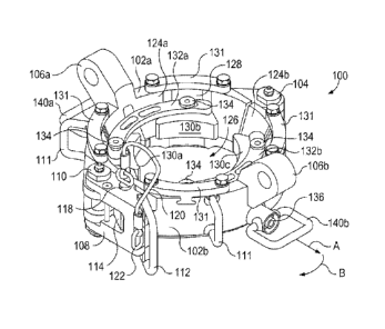
[0020] Figures 1-3 illustrate an exemplary oilfield elevator 100, according to
one or more
embodiments disclosed. The elevator 100 is moveable between a closed position,
as shown
in Figures 1 and 2, and an open position, as shown in Figure 3. In one
embodiment, the
elevator 100 may be a single-joint elevator configured to grasp onto and
position a singular
tubular segment, such as a drill pipe or casing, for coupling to a tubular
string. The elevator
100 may include a first body half 102a and a second body half 102b pivotally
connected at a
hinge 104. Each body half 102a,b may have a lifting ear 106a and 106b,
respectively,
integrally formed therewith or connected thereto and configured to be coupled
to or otherwise
receive links (not shown) in order to position the elevator 100 during tubular
makeup
operations.
CA 02834880 2013-10-31
WO 2012/151148 PCT/US2012/035752
[0021] The elevator 100 is moveable between the open and closed positions by
pivoting each
body half 102a,b about the axis of the hinge 104. To help accommodate this
movement, one
or more positioning handles 111 may be attached to the exterior of the first
and second halves
102a,b to be grasped by a user to manipulate their general position. In other
embodiments,
the positioning handles 111 may be omitted and an automated opening/closing
system (not
shown) may be implemented to mechanically open/close the elevator 100. For
example, the
elevator 100 may be opened/closed using mechanical devices such as hydraulics,
servos,
gearing, etc., without departing from the scope of the disclosure.
[0022] The elevator 100 may be secured in the closed position with a locking
apparatus 108
pivotally-coupled to the first body half 102a with a pivotal coupling 110. In
other embodiments,
the locking apparatus 108 may be pivotally coupled to the second body half
102b, without
departing from the scope of the disclosure. In one embodiment, the pivotal
coupling 110 may
be spring loaded. A locking handle 112 projects from the locking apparatus 108
and may be
grasped by a user to manually bring the first body half 102a into proximity of
the second body
half 102b. Once the first and second body halves 102a,b are proximally
aligned, the locking
mechanism 108 may be configured to extend over a latch 114 (best seen in
Figure 3)
integrally-formed with the second body half 102b. The latch 114 may define a
perforation 116
(Figure 3) adapted to receive a pin 118 (partially shown). The pin 118 may be
extendable
through corresponding perforations (not shown) defined in the locking
mechanism 108 and into
the perforation 116 to secure the locking mechanism 108 in the closed
position. As illustrated,
the pin 118 may be attached to a cord or cable 120 that is anchored to the
locking mechanism
108 at an anchor point 122.
[0023] The first and second body halves 102a and 102b each define an inner
circumferential
surface 124a and 124b, respectively. When the elevator 100 is in the closed
position, the
inner circumferential surfaces 124a,b cooperatively define a generally
circular opening or
throat 126 that may be configured to receive and secure a tubular or casing
segment. The
inner circumferential surfaces 124a,b may further define a series of tapered
slots 128; one slot
is 128 shown in Figures 1 and 2, and two slots 128 are shown in Figure 3. The
term "tapered"
as used herein refers to the slots 120 being inclined to the axis of the
throat 126, such as being
downwardly and inwardly-tapered with respect to the axis of the throat 126.
[0024] The tapered slots 128 may be equidistantly-spaced from each other about
the inner
circumferential surfaces 124a,b. In one embodiment, each inner circumferential
surface
6
CA 02834880 2013-10-31
WO 2012/151148 PCT/US2012/035752
124a,b may define a total of two slots 128, but in other embodiments more or
less than two
slots 128 may be provided. Moreover, the number of slots 128 defined in either
inner
circumferential surface 124a,b does not necessarily have to be equal, but may
vary depending
on the application.
[0025] Each slot 128 may be adapted to slidably receive a slip 130, such as
slips 130a, 130b,
130c, and 130d (only slips 130a,b,c are shown in Figure 1). As illustrated,
the slots 128
defined in the first inner circumferential surface 124a may slidably receive
the first slip 130a
and the second slip 130b, while the slots 128 defined in the second inner
circumferential
surface 124b may slidably receive the third slip 130c and the fourth slip
130d. Each slip 130a-
d may be partially cylindrical and configured to engage the outside surface of
a tubular
segment, as will be described in more detail below.
[0026] During elevator 100 operation, the slips 130a-d may be able to
translate vertically within
their respective slots 128. To facilitate this vertical translation, each slot
128 may include one
or more rails 129 (Figures 2 and 3) configured to seat a respective slip 130a-
d. The rails 129
may be configured to extend through a portion of the respective slip 130a-d,
thereby providing
a fixed translation path for each slip 130a-d. In at least one embodiment,
each rail 129 may be
encompassed by a compression spring 152 (Figures 4 and 5) adapted to
continuously bias the
respective slip 130a-d upward and into an "open" position. In other
embodiments, the
compression springs 152 may be separate from the rails 129 but nonetheless
work in concert
therewith to facilitate the vertical translation of the slips 130a-d.
[0027] Each slip 130a-d may be maintained within its respective slot 128 using
a retainer plate
131 fastened to the first or second body halves 102a,b adjacent the upper end
of each slot
128. The retainer plates 131 may be fastened to the first or second body
halves 102a,b by any
known method including, but not limited to, mechanical fasteners.
[0028] A first timing bar 132a may be used to moveably couple the first slip
130a to the second
slip 130b, such that when the first slip 130a moves, the second slip 130b
moves as well, and
vice versa. A second timing bar 132b may be used to moveably couple the third
slip 130c to
the fourth slip 130d such that when the third slip 130c moves, the fourth slip
130d moves as
well, and vice versa. One or more mechanical fasteners 134 (e.g., bolts,
screws, etc.) may be
used to secure the timing bars 132a,b to the respective slips 130a-d. In other
embodiments,
however, the timing bars 132a,b may be attached to the respective slips 130a-d
via other
7
CA 02834880 2013-10-31
WO 2012/151148 PCT/US2012/035752
attachments, such as welding, brazing, adhesives, or combinations thereof,
without departing
from the scope of the disclosure.
[0029] The elevator 100 may further include first and second tension handles
140a and 140b
pivotally coupled to the first and second body halves 102a and 102b,
respectively. Figure 1
shows the tension handles 140a,b in a "locked" position, and Figures 2 and 3
show the tension
handles 140a,b in an "unlocked" position. In the locked position, each tension
handle 140a,b
may rest or otherwise be seated within a recessed pocket 141 (Figure 2)
defined in the outer
circumferential surface of each body half 102a,b, respectively. Moreover, each
tension handle
140a,b may include a spring-loaded body fixture 136 (Figure 1) adapted to bias
the tension
handle 140a,b into its respective recessed pocket 141.
[0030] To unlock the tension handles 140a,b, a user may pull radially-outward
on the tension
handle 140b (or 140a), as indicated by arrow A in Figure 1, to remove it from
the recessed
pocket 141. Once removed from the recessed pocket 141, the tension handle 140b
may
swivel downward and back toward the body half 140b, as indicated by arrow B.
Locking the
tension handles 140a,b back in place within the recessed pockets 141 can be
accomplished by
a reversal of the above-described steps.
[0031] Referring now to Figures 4 and 5, with continuing reference to Figures
1-3, illustrated
are isometric views of the elevator 100 with the tension handles 140a,b in the
unlocked (Figure
4) and locked (Figure 5) positions, according to one or more embodiments of
the disclosure.
Although only the first body half 102a, including the first tension handle
140a, is shown in
Figures 4 and 5 and described below, it will be appreciated that the following
description is
equally applicable to the components of the second body half 102b, especially
including the
second tension handle 140b, but will not be discussed herein for the sake of
brevity.
[0032] As illustrated, the first tension handle 140a may include a body 138
that extends
generally into the throat 126 through an opening 139 defined in the first body
half 102a. The
opening 139 may generally extend from the outer surface of the first body half
102a to the
inner circumferential surface 124a. The body 138 may terminate at a connection
point 142
configured to be coupled to a biasing member 144, for example, at a first end
146 of the
biasing member 144. In one embodiment, the biasing member 144 may be a tension
spring,
as illustrated. In other embodiments, however, the biasing member 144 may be
any other
device capable of providing a biasing force such as, but not limited to,
pneumatic devices,
hydraulic devices, servo devices, electromagnets, or combinations thereof.
8
CA 02834880 2013-10-31
WO 2012/151148 PCT/US2012/035752
[0033] In the illustrated embodiment, the connection point 142 includes a ring
structure, but in
other embodiments the connection point 142 may include any other type of
structure capable
of being coupled to the biasing member 144. The biasing member 144 may also
include a
second end 148 configured to be coupled to the first timing bar 132a. In one
embodiment, the
first timing bar 132a may define one or more holes 150 for receiving or
otherwise securing the
second end 148 of the biasing member 144. It will be appreciated, however,
that the second
end 148 may be secured to the first timing bar 132a in any known manner,
without departing
from the scope of the disclosure.
[0034] When the first tension handle 140a is in the unlocked position (Figure
4), the biasing
member 144 is able to retract, at least partially, and thereby reduce the
downward force
exhibited on the first timing bar 132a. As the downward force on the timing
bar 132a is
removed or otherwise diminished, the compression springs 152 are able to
expand and force
the first and second slips 130a,b vertically-upward and into the open position
within their
respective slots 128. Since the slots 128 are inclined to the axis of the
throat 126, upward
axial movement of the slips 130a,b simultaneously results in a radial movement
of the slips
130a,b away from the center of the throat 126. Consequently, in the open
position the slips
130a,b provide the largest throat 126 area.
[0035] When the first tension handle 140a is returned to its locked position
(Figure 5), the
connection point 142 pulls down on and engages the biasing member 144 which
transmits a
generally downward force on the first timing bar 132a. As a result, the first
timing bar 132a
conveys a generally downward force on the first and second slips 130a,b and
their
accompanying compression springs 152, thereby causing the axial downward
movement of
the slips 130a,b. Moreover, because of the tapered disposition of the slots
128, downward
axial movement of the slips 130a,b simultaneously results in a radial movement
of the slips
130a,b toward the center of the throat 126. Consequently, in the closed
position the slips
130a,b present the smallest throat 126 area for the elevator 100.
[0036] Referring to Figure 6, illustrated is a cross-sectional view of the
exemplary elevator 100
as it engages a casing or tubular segment 602, according to one or more
embodiments. In
one embodiment, the tubular segment 602 may include a sleeve 604 coupled
thereto. In other
embodiments, the sleeve 604 may be a collar or other upset that is integrally-
formed with the
tubular segment 602. The sleeve 604 may include a circumferential shoulder 606
adapted to
9
CA 02834880 2013-10-31
WO 2012/151148 PCT/US2012/035752
engage the elevator 100 at each slip 130a-d (only the second and third slips
130b and 130d
are shown in Figure 6).
[0037] The slips 130a-d may engage the tapered surface 608 of the respective
slot 128 with a
corresponding inclined surface 610. Via this sloping engagement between the
tapered surface
608 and the inclined surface 610, the radial movement of the slips 130a-d
toward or away from
the center of the elevator 100 is realized. Consequently, the collective
radial circumference of
the slips 130a-d is able to increase and/or decrease over a fixed range,
thereby manipulating
the radius of the throat 126 and enabling the elevator 100 to receive and
properly secure
tubular segments 602 having a varied and increased range of an outside
diameter Od. As will
be appreciated, this may be achieved without requiring any adjustment to or
replacement of
the elevator 100.
[0038] With the elevator 100 in the open position, as shown in Figure 3, the
tubular segment
602 may enter the throat 126. Once the elevator 100 is closed, the tension
handles 140a,b
(Figures 1-3) may be moved into the locked position, as shown in Figure 5.
Moving the
tension handles 140a,b into the locked position applies a spring force on the
slips 130a-d that
results in the axial-downward and radial-inward movement of the slips 130a-d.
As illustrated in
Figure 6, the second and third slips 130b,d will move axially-downward and
radially-inward
until eventually engaging the outside surface 612 of the tubular segment 602.
The weight of
the tubular segment 602 may shift the tubular segment 602 vertically until the
circumferential
shoulder 606 engages the slips 130b,d, thereby impeding its further downward
progress. Via
this sloping engagement between the tapered surface 608 and the inclined
surface 610 of
each slip 130b,d, any increased force in the downward direction against the
slips 130b,d only
tightens the engagement with the slips 130b,d on the outside diameter Od of
the tubular
segment 602.
[0039] Once the tubular segment 602 is properly coupled to a tubular string or
otherwise
securely captured by another lifting mechanism, the tension handles 140a,b may
be unlocked
in preparation for receiving a new tubular segment 602. Unlocking the tension
handles 140a,b
releases the spring forces on the slips 130a-d and allows the slips 130a-d to
move axially-
upward and into the open position, thereby releasing the tubular segment 602
from
engagement with the elevator 100.
[0040] Referring to Figure 7, illustrated is an isometric view of the
exemplary oilfield elevator
100 engaged with a tubular segment 702, according to one or more embodiments
disclosed.
CA 02834880 2013-10-31
WO 2012/151148 PCT/US2012/035752
As described above, the elevator may be engaged to the tubular segment 702 at
a sleeve 704.
Those skilled in the art will recognize the several advantages provided by the
elevator 100.
For example, the elevator 100 is able to securely grasp onto multiple outside
diameters within
a nominal tubular segment 702 size. As a result, significant savings in money
and time may
be gained that would otherwise be spent in removing and replacing the elevator
100 or
adjusting the settings for different outside diameters.
[0041] As used herein, the term "single-joint elevator" is intended to
distinguish the elevator
from a string elevator that is used to support the weight of the entire pipe
string. Rather, a
"single-joint elevator" is used to grip and lift a tubular segment as is
necessary to add or
remove the tubular segment to or from a tubular string. Furthermore, a pipe or
tubular
"segment", as that term is used herein, is inclusive of either a single pipe
or tubular joint or a
stand made up of multiple joints of a pipe or other tubular that will be
lifted as a unit. In the
context of the present disclosure, a tubular segment does not include a
tubular string that
extends into the well.
[0042] Referring now to Figure 8, illustrated is a method 800 for engaging a
tubular segment.
In one embodiment, the method 800 may include positioning an elevator adjacent
the tubular
segment, as at 802. The elevator may include first and second body halves that
have slips
that are slidably received within corresponding tapered slots. The
corresponding tapered slots
may be defined in the first and second body halves. Moreover, a first timing
bar may be
coupled to the slips in the first body half and a second timing bar may be
coupled to the slips in
the second body half. The method 800 may further include closing the first and
second body
halves around the tubular segment, as at 804.
[0043] First and second tension handles may then be moved from an unlocked
position to a
locked position, as at 806. In one embodiment, the first and second tension
handles may be
pivotally-coupled to the first and second body halves, respectively, and each
tension handle
may have a body that terminates at a connection point. The method 800 may
further include
applying a downward force on the first and second timing bars with first and
second biasing
members, as at 808. The first and second biasing members may each have a first
end
coupled to the connection point of the first and second tension handles,
respectively, and a
second end coupled to the first and second timing bars, respectively. The
downward force
may then be transmitted from the first and second timing bars to the slips, as
at 810. The slips
may be configured to translate vertically within the tapered slots and at the
same time translate
CA 02834880 2015-04-01
radially with respect to the first and second body halves in response to the
downward force.
Accordingly, the slips may translate vertically and radially until coming into
contact with an
outside surface of the tubular segment.
[00441 The scope of the claims should not be limited by particular embodiments
set
forth herein, but should be construed in a manner consistent with the
specification as
a whole,
=
12