Note: Descriptions are shown in the official language in which they were submitted.
CA 02841944 2014-01-14
WO 2013/010152 PCT/US2012/046819
VARIABLE-SPEED IRRIGATION SYSTEM
BACKGROUND
[0001] Modern day agriculture has become increasingly efficient in the past
century and this
trend must continue in order to produce a sufficient food supply for the
increasing world
population. A notable advancement in agricultural production was the
introduction of
mechanized irrigation systems, such as the center pivot and the linear move
irrigation
systems. These irrigation systems make it possible to irrigate entire fields,
and reduce a crop
yield's vulnerability to extreme weather conditions. The ability to monitor
and to control the
amount of water and/or nutrients (applicants) applied to an agricultural field
has increased the
amount of farmable acres in the world and increases the likelihood of a
profitable crop yield.
These irrigation systems typically include a control device configured to
furnish a user
interface allowing the operator to monitor and control one or more functions
or operations of
the irrigation system.
SUMMARY
[0002] An irrigation system is disclosed that is configured to maintain a near
straight (e.g., an
at least zero degree (0 )) alignment. In an implementation, an irrigation
system includes
multiple interconnected spans which are supported by multiple tower
structures. Each tower
structure includes a variable-speed drive unit for selectively driving a tower
structure at a
selected speed. In a specific implementation, the variable-speed drive units
may be switched
reluctance motors. The irrigation system also includes multiple sensors that
are each
associated with a corresponding span to determine an alignment of the
corresponding span
with respect to adjacent spans. Each of the sensors is in communication with a
corresponding
variable-drive control unit. Each of the variable-drive control units are
configured to control
the selected speed of a corresponding variable-speed drive unit to maintain
the interconnected
spans in a substantially linear orientation with respect to adjacent ones of
the plurality of
interconnected spans along a generally longitudinally oriented axis (e.g.,
maintain alignment
of the spans with respect to each other). In a specific implementation, the
variable-drive
control units may be in direct communication with the corresponding sensor.
CA 02841944 2014-01-14
WO 2013/010152 PCT/US2012/046819
2
[0003] This Summary is provided solely to introduce subject matter that is
fully described in
the Detailed Description and Drawings. Accordingly, the Summary should not be
considered
to describe essential features nor be used to determine scope of the claims.
BRIEF DESCRIPTION OF THE DRAWINGS
[0004] The detailed description is described with reference to the
accompanying figures. In
the figures, the left-most digit(s) of a reference number identifies the
figure in which the
reference number first appears. The use of the same reference numbers in
different instances
in the description and the figures may indicate similar or identical items.
[0005] FIG. lA is an isometric diagrammatic perspective view of an irrigation
system in
accordance with an example implementation of the present disclosure.
[0006] FIG. 1B is a block diagram illustrating a control device of the
irrigation system shown
in FIG. lA in accordance with an example implementation of the present
disclosure.
[0007] FIG. 1C is a block diagram illustrating a sensor in electronic
communication with a
variable-drive control unit, wherein the variable control device is configured
to control the
selected speed of a variable-drive unit based upon an alignment of
corresponding adjacent
spans as determined by the sensor.
[0008] FIG. 1D is a block diagram illustrating an example implementation of a
variable-drive
control unit that is configured to control a variable-drive unit, wherein the
variable-drive
control unit includes a processor, a memory, and a communication module
configured to
communicate with a sensor and the variable-drive unit.
DETAILED DESCRIPTION
Overview
[0009] Most irrigation systems, such as center pivot irrigation systems,
include drive units
(motors) located on the drive towers to propel the irrigation system. Many of
these rely on
fixed rate motors due to their relative simplicity and robustness. However,
such systems can
only adjust the relative alignment of various span portions by alternatively
starting and
stopping the drives. This results in drive towers coming to a complete stop
and then
requiring a large impulse of power to start the tower again. The starting and
stopping places
undue stress on various components of the irrigation system, which can
accelerate wear and
CA 02841944 2014-01-14
WO 2013/010152 PCT/US2012/046819
3
increase maintenance costs. The irregular motion can also cause uneven
application of
irrigation water and/or chemicals to the field. This results in waste of both
water and
chemicals. The irregular motion can also cause errors in alignment or in
determining the
position of the end of the machine. This can result in errors in operations
based on position.
[0010] Accordingly, an irrigation system is disclosed that is configured to
maintain a near
straight (e.g., an at least zero degree (0 )) alignment. In an implementation,
an irrigation system
includes multiple interconnected spans which are supported by multiple tower
structures.
Each tower structure includes a variable-speed drive unit for selectively
driving a tower
structure at a selected speed. The irrigation system also includes multiple
sensors that are
each associated with a corresponding span to determine an alignment of the
corresponding
span with respect to adjacent spans. Each of the sensors is in communication
with a
corresponding variable-drive control unit. Each of the variable-drive control
units are
configured to control the selected speed of a corresponding variable-speed
drive unit to
maintain the interconnected spans in a substantially linear orientation with
respect to adjacent
ones of the plurality of interconnected spans along a generally longitudinally
oriented axis
(e.g., maintain alignment of the spans with respect to each other).
Example Implementations
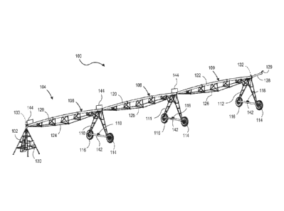
[0011] FIG. lA illustrates a self-propelled (e.g., mechanized) irrigation
system (assembly)
100 in accordance with example implementations of the present disclosure.
Examples of
self-propelled irrigation systems include a center pivot irrigation system, a
linear move
irrigation system, or the like. FIG. lA illustrates an embodiment of the
present disclosure
where the irrigation system 100 is a center pivot irrigation system. However,
it is
contemplated that the present disclosure may be implemented in other self-
propelled
irrigation systems (e.g., linear move irrigation systems). As shown, the
system 100 includes
a center pivot structure 102, a main section assembly 104 (irrigation section
assembly)
coupled (e.g., connected) to the center pivot structure 102. The center pivot
structure 102 has
access to a well, a water repository (e.g., water tank), or other fluid
source, to furnish water to
the irrigation system 100. For instance, the well may be located under the
center pivot
structure 102. In another instance, the well may be in close proximity to the
cultivation area
(e.g., field). The fluid source may be coupled to a repository or other source
of agricultural
products to inject fertilizers, pesticides, and/or other chemicals into the
fluids to create an
CA 02841944 2014-01-14
WO 2013/010152 PCT/US2012/046819
4
applicant for application during irrigation. Thus, the applicant may be water,
fertilizer,
herbicide, pesticide, combinations thereof, or the like. The irrigation system
100 may be
coupled to a fluid displacement device (e.g., a pump assembly) configured to
furnish
applicant throughout the irrigation system 100. For example, the fluid
displacement device
may assist in displacing fluid from the fluid source (e.g., well, water
repository, etc.) to the
conduit portions of the irrigation system which are described herein. The
center pivot
structure 102 can be fixed or can be towable such that an operator can move
the irrigation
system 100 from one field to another. In an implementation, the center pivot
structure 102
may comprise a frame assembly (e.g., galvanized steel frame assembly, and so
forth).
[0012] The main section assembly 104 includes a number of interconnected spans
106, 108,
109 (e.g., irrigation spans) supported by one or more tower structures 110,
111 (intermediate
tower structures) and an end tower structure 112. The tower structures 110,
111, 112 may be
any tower configuration known in the art to adequately support the conduits
(e.g., water pipe
sections) described herein. It is understood that the section assembly 104 may
include any
number of spans and tower structures.
[0013] The tower structures 110, 111 and the end tower structure 112 each
include wheels
114, 116, to assist in traversing the irrigation system 100 (e.g., allowing
the main section
assembly 104 to pivot) about a cultivation area (e.g., field). In an
implementation, the wheels
114, 116 may be driven by a suitable variable-drive unit 118 (e.g., drive
motor), or the like, to
assist in traversing the system 100 about the specified area. For example,
each tower
structure 110 may include a drive unit 118 to propel the respective tower
structure 110, 111,
112 (and the irrigation system 100) through the cultivation area. In one or
more
implementations, the drive units 118 comprise variable-speed motors that are
configured to
selectively drive a tower structure at a selected speed. For example, the
drive units 118 may
comprise electric switched reluctance motors configured to drive the
irrigation system 100 in
a forward direction or a reverse direction. Typically, the alignment between
each span 106,
108, 109 (e.g., machine alignment) of the irrigation system 100 is maintained
by a suitable
mechanical linkage at each drive unit span joint. The drive unit span joint is
configured as a
potentiometer, or other sensor, that serves to accelerate or decelerate the
respective drive unit
118 (switched reluctance motors, which are described in greater detail below)
to at least
substantially keep the respective span 106, 108, 109 in alignment with the
other irrigation
CA 02841944 2014-01-14
WO 2013/010152 PCT/US2012/046819
span. Alignment may be defined as each span 106, 108, 109 being aligned with
one or more
adjacent spans along a generally linear longitudinal axis (e.g., defined with
respect to a
generally horizontal surface, such as the ground).
[0014] As shown in FIG. 1A, each span 106, 108 includes conduits 120, 121, 122
(e.g.,
pipes) that are configured to carry (e.g., transport, provide, and so forth)
liquid (e.g.,
applicant) along the length of the system 100 to one or more applicant
dispersal assemblies
that are configured to irrigate the cultivation area. Each conduit 120, 121,
122 may be
coupled to one another to allow fluid communication between each conduit. In
an
implementation, the conduits 120, 121, 122 may be supported by truss-type
framework
structures 124, 125, 126. Thus, the main fluid displacement device may be
configured to
displace applicant through the conduits 120, 121, 122. As shown in FIG. 1A,
the irrigation
system 100 also includes a cantilevered boom structure 128 that extends
outwardly from the
end tower structure 112. In one or more implementations, the cantilevered boom
128
includes an end gun 129 (e.g., end gun 129 is mounted to the cantilevered boom
128). The
end gun 129 may be a suitable pressure sprayer configured to be activated at
the corners of a
field, or other designated areas, to increase the amount of land that can be
irrigated.
[0015] As shown in FIGS. lA and 1B, the irrigation system 100 includes a
control device
130 (e.g., control panel) that is in electronic communication with one or more
components of
the system 100. For example, the control device 130 may be in electronic
communication
with one or more tower boxes mounted at one or more tower structures 110, 111,
112, and a
position sensor 132 utilized to determine an approximate position of the
irrigation system
(e.g., determining the approximate position of the end tower structure 112
within the
cultivation area with respect to the center pivot structure 102). In an
implementation, the
position sensor 132 may be a GPS sensor (e.g., GPS receiver), or the like,
mounted to the end
tower structure 112 configured to transmit signals representing the position
of the end tower
structure to the control device 130. As described herein, the control device
130 is configured
to determine the radial position of the main section assembly 104 with respect
to the center
pivot structure 102. In another implementation, the position sensor 132 may be
an angle
sensor 133 configured to facilitate determination of the rotational position
of the main section
assembly 104. The angle sensor 133 may be mounted to the center pivot
structure 102 to
assist in determining the rotational position of the main section assembly
104.
CA 02841944 2014-01-14
WO 2013/010152 PCT/US2012/046819
6
[0016] In an implementation, the control device 130 is mounted to the central
pivot structure
102, a control cart, or a tower structure 110, 111, 112. The control device
130 is generally
located on the structural element of the irrigation system 100 where the
applicant/water is
introduced into the irrigation system; however, other configurations known in
the art are
within the scope of the present disclosure.
[0017] The control device 130 is configured to monitor operating conditions
and configured
to control various functions of the irrigation system 100. In certain
implementations, the
control device 130 actively monitors the irrigation system's 100 function and
performance
including, but not limited to: a position of one or more conduit sections 120,
121, 122 or
tower structures 110, 111, 112 (e.g., the position of the main section
assembly 104), whether
the irrigation system 100 is powered on or off, a voltage parameter associated
with the
irrigation system 100, a motor speed parameter associated with the irrigation
system 100, an
approximate ground speed parameter associated with the irrigation system 100,
a direction
parameter associated with the irrigation system 100, a diagnostic parameter
associated with
the irrigation system 100, whether the applicant is being supplied to the
irrigation system 100
(e.g., whether the fluid displacement device is operational), whether the Stop
in Slot (SIS) is
powered on or off, an applicant pressure associated with the irrigation system
100, a time
parameter, a date parameter, a field position parameter of the irrigation
system components,
end-gun status, and whether the programs (e.g., software programs, etc.) are
running
properly. The control device 130 also controls the irrigation system's 100
functions and
settings including, but not limited to: start and stop, selectively powering
the main fluid
displacement device, an applicant application depth parameter, the direction
of travel
associated with the irrigation system 100, selectively powering the SIS,
automatically
reversing or stopping the irrigation system 100, automatically restarting the
irrigation system
100, providing an operator auxiliary control to the system 100, writing and
editing irrigation
programs (e.g., irrigation software programs), and controlling sector and
sequential programs
(e.g., software programs). In another implementation, the control device 130
may cause an
alert to be issued to the operator if there are any errors in the operation of
the irrigation
system 100 or if any of the functions or conditions monitored by the control
device 130 have
been compromised (e.g., ceased operation or are outside an acceptable range).
CA 02841944 2014-01-14
WO 2013/010152 PCT/US2012/046819
7
[0018] The control device 130 may be housed in a weather-proof box and, as
shown in FIG.
1B, includes at least a memory 134 to store one or more software programs
(e.g., software
modules), a processor 136 communicatively coupled to the memory 134, a user
interface 138
(e.g., graphical user interface, etc.), and a communications module 140 (e.g.,
transmitter,
receiver, transceiver, etc.). The memory 134 is an example of tangible
computer-readable
media that provides storage functionality to store various data associated
with the operation
of the control device 130, such as software programs/modules and code segments
mentioned
herein, or other data to instruct the processor 136 to perform the steps
described herein.
[0019] As described above, the irrigation system may include a plurality of
drive units 118
mounted to each tower structure 110, 111, 112. As shown in FIG. 1C, each drive
unit 118 may
comprise a switched reluctance motor (SRM) 142. The switched reluctance motor
142 is an
electric motor configured to operate utilizing reluctance torque. The use of
switched reluctance
motors 142 allows for continuous speed adjustment (as compared to motors not
utilizing switched
reluctance configurations), which allows for dynamic ("on-the-fly") alignment
adjustments of the
spans 106, 108, 109. Additionally, the switched reluctance motors 142 allow
for the constant
movement of the center pivot irrigation systems (as compared to center pivot
irrigation systems
not having switched reluctance motors), which may allow for greater uniform
application of
water and/or chemicals while lessening waste.
[0020] As shown in FIG. 1C, the variable-drive units 118 may each include a
variable-drive
control unit 143. As shown in FIG. 1D, the variable-drive control unit 143
includes a processor
202 is configured to provide processing functionality to the variable-drive
control unit 143.
Thus, the processor 202 may execute one or more software programs and/or
instructions
described herein. The variable-drive control unit 143 also includes a memory
204, which is
an example of tangible computer-readable media that provides storage
functionality to store
various data associated with the operation of the variable-drive control unit
143, such as
software programs/modules and code segments mentioned herein, or other data to
instruct the
processor 202 to perform the steps described herein. In an implementation, the
variable-drive
control unit 143 is directly connected with the respective sensor 144 (e.g.,
via a wired
connection). In this implementation, the variable control unit 143 is also
directly connected
to the respective switched reluctance motor 142 (e.g., via a wired
connection). In another
implementation, the variable-drive control unit 143 may include a
communication module
CA 02841944 2014-01-14
WO 2013/010152 PCT/US2012/046819
8
206, which is configured to communicate with other components (e.g., switched
reluctance
motors 142, sensors 144) over a communication network (e.g., a wireless
network, a wired
network, etc.). For example, the communication module 206 may be directed
coupled (e.g.,
via one or more wires, or the like) to a corresponding variable-drive unit
118, as well as a
corresponding sensor 144. The communication module 206 may be representative
of a
variety of communication components and functionality, including, but not
limited to: one or
more antennas, a transmitter and/or receiver, a transceiver, or the like.
While FIG. 1D
illustrates that the variable-drive control unit 143 is integrated (e.g.,
housed within) with the
variable-drive unit 118, it is understood that the variable-drive control unit
143 may be a
standalone unit.
[0021] As shown in FIG. 1C, each of the sensors 144 is in communication with
the respective
variable-drive control unit 143. In a specific implementation, the sensors are
in direct electronic
communication with the corresponding variable-drive control unit 143.
Previously, irrigation
systems may have employed rod-and-switch actuators. These actuators may be
replaced with the
sensors 144 configured to monitor (e.g., determine) the span-to-span alignment
of the irrigation
system 100. For example, the sensors 144 are configured to determine an angle
between the
corresponding spans. In one or more implementations, the sensors 144 may be
potentiometers,
captive alignment sensors, laser based alignment sensors, non-contact
proximity sensors, or other
devices capable of quantifiably measuring the span alignment (e.g.,
determining an angle value
between the corresponding spans) rather than merely determining if the
respective span 106, 108,
109 is out of alignment beyond a preset maximum value. As described above, the
sensors 144
(potentiometers, the captive alignment sensors, the laser based alignment
sensors, and/or the non-
contact proximity sensors) are in electronic communication with the variable-
drive control unit
143. In response, the variable-drive control unit 143 is configured to furnish
(e.g., provide,
generate, transmit) one or more drive unit signals to control the switched
reluctance motor 142.
For example, the processor 202 of the variable-drive control unit 143 is
configured to translate
the angle information furnished by the sensor 144 into speed information that
is utilized to control
the switched reluctance motor 142 (e.g., control the speed of the
corresponding span 106, 108,
109). Thus, the variable-drive control unit 143 may furnish one or more drive
unit signals that
are configured to cause a specified drive unit 118 to modify the speed (e.g.,
increase the speed,
decrease the speed) of the unit 118 (e.g., switched reluctance motor 142),
which causes the
corresponding span 106, 108, 109 to vary in speed. In an implementation, the
control device 130
CA 02841944 2014-01-14
WO 2013/010152 PCT/US2012/046819
9
may be configured to communicate with each variable-drive control unit during
operation of the
irrigation system 100. For example, the variable-drive control unit 143 may be
configured to
furnish diagnostic and/or performance information regarding the variable-drive
unit 118 to the
control device 130.
[0022] In an implementation, a sensor 144 is configured to continually monitor
(determine) the
alignment values (e.g., angles) of the corresponding spans 106, 108, 109. In
turn, the variable-
drive control unit 143 is configured to furnish a drive unit signal configured
to cause the
corresponding drive unit 118 to continuously modify the speed of the drive
unit 118 (e.g., modify
the speed of the switched reluctance motor 142) to re-align the corresponding
mis-aligned span
106, 108, 109. Thus, the variable-drive control unit 143 is configured to
continuously provide
signals, based upon the sensor 144 signal, to cause at least substantially
near-perfect (e.g., near-
horizontal alignment) between the corresponding spans by way of the switched-
reluctance motors
142. For example, the speed of the drive unit 118 may be varied (via one or
more drive unit
signals) based upon a deviation from a zero degree (0 span to span
alignment). In one or more
implementations, the irrigation system 100 (e.g., sensors 144, variable-drive
control unit 143,
etc.) may utilize one or more motor control techniques to adjust the speed of
the drive units 118
and/or measure the alignment of a particular span. For example, the irrigation
system 100 may
utilize a proportional-integral-derivative control algorithm, or the like, to
fine tune the speed of a
particular drive unit 118. The variable-drive control unit 143 is configured
to continuously
furnish one or more drive unit signals to the drive units 118 when the sensor
144 determines that
a particular span is mis-aligned.
[0023] Thus, in operation, drive unit (control) signals configured to adjust
the set speed of a
particular drive unit 118 are furnished to the particular drive unit 118,
which causes a drive unit
speed adjustment. As described above, the drive unit signals may be based on
potentiometer
signals, captive alignment sensor signals, laser based alignment sensor
signals, non-contact
proximity sensor signals, and/or other parameters useful in determining a new
set speed for a
particular drive unit. As described above, the variable-drive control unit 143
includes a processor
202 that is configured to receive and to utilize data (information) from the
tower structures 110,
111, 112 in determining the set speed for a particular drive unit 118. In an
implementation, the
processor 202 may comprise a microcontroller that includes dedicated logic
(e.g., circuitry) for
controlling the variable-drive units 118 and/or the switched reluctance motors
142. For example,
the variable-drive control unit 143 may be in communication with each of the
tower structures
CA 02841944 2014-01-14
WO 2013/010152 PCT/US2012/046819
110, 111, 112 by way of sensors 144, or the like. As described above, this may
allow for finer
speed control and dynamic alignment correction of the irrigation system 100.
Conclusion
[0024] Although the subject matter has been described in language specific to
structural
features and/or process operations, it is to be understood that the subject
matter defined in the
appended claims is not necessarily limited to the specific features or acts
described above.
Rather, the specific features and acts described above are disclosed as
example forms of
implementing the claims.