Note: Descriptions are shown in the official language in which they were submitted.
CA 02862369 2014-06-27
WO 2013/102190
PCT/US2012/072270
IMAGE-OVERLAY MEDICAL EVALUATION
DEVICES AND TECHNIQUES
FIELD OF THE INVENTION
[0001] The present invention relates to medical techniques or methods
involving the
attachment of prostheses or implants to body tissues, for devices and
equipment used in such
techniques, and for the manufacturing and evaluation of surgical guides used
in attaching
prostheses or implants to body tissues.
BACKGROUND OF THE INVENTION
[0002] Typical methods for attaching prostheses or implants (such as
dental implants, for
example) to body tissues (such as bone) involve multiple radiographic scans of
at least a
portion of the body with different forms of potentially harmful radiation.
Such radiographic
scans may be performed using X-ray, computed tomography ("CT") scanning, cone
beam
computed tomography ("CBCT"), or the like, all of which use ionizing radiation
to acquire
diagnostic images. The scans are typically performed prior to a surgical
procedure, such as to
evaluate pre-operative internal anatomy, and may be performed again during
and/or after the
surgical procedure, such as to evaluate the positioning of prostheses,
implants, tools, etc.
during and/or after surgery, such as to help ensure that the desired effect is
achieved.
However, repeated scans expose medical patients and medical personnel to
repeated doses of
radiation. It also can be prohibitively costly and time-consuming to use non-
ionizing
radiation, such as magnetic resonance imaging ("MRI"), for such evaluations.
[0003] The desire for successful and predictable surgical results has led
to significant
advancement in dentistry and medicine in recent years. For example, accurate
placement and
retention of dental implants has significantly improved with the introduction
of cone beam
computed tomography (CBCT). Studies have demonstrated that CBCT technology can
provide benefits of increased accuracy and lower radiation exposure compared
to other
radiographic scanning technologies. Additionally, the advent of CBCT in
dentistry has led to
the development of more precise surgical guides for use during dental implant
placement.
[0004] In accordance with earlier techniques of surgical guide fabrication
in the dental
environment, "bench-top surgical guides" have been made by a clinician or
laboratory
personnel based on a diagnostic wax-up of the patient anatomy, simply by
marking on a
diagnostic cast of an anatomical portion of the patient. Although such methods
typically
provide improved accuracy over medical procedures (e.g., drilling osteotomies)
free-hand or
-1-
CA 02862369 2014-06-27
WO 2013/102190
PCT/US2012/072270
without the use of a guide, such bench-top surgical guides can still be
inaccurate and
unpredictable.
[0005] Known techniques of fabricating more accurate surgical guides may
begin with
fabricating an accurate model of a patient's dentition, such as by making an
impression and
pouring a cast, or using rapid prototyping techniques such as
stereolithography, which can be
used to produce a model directly from CT, CBCT, MRI, or laser scan data or the
like. Some
commercial systems for producing such CT-guided surgical guides use various
radiopaque
markers, navigation software, and imaging processes. However, typical
commercial methods
of surgical guide fabrication can be tedious and expensive for the practicing
clinician, and
can take days or weeks to complete, especially when some of the steps are
completed at an
off-site location and require shipping of casts, surgical guides, and the
like. Moreover, even
after a clinician uses a surgical guide to place one or more dental implants,
confirming the
accuracy of placement has typically required exposing the patient to a post-
surgical X-ray or
CBCT or CT scan, resulting in additional radiation exposure to the patient.
[0006] It is also known to take several mid-surgical periapical (i.e.,
around the apex of the
root of a tooth) X-rays to assess surgical drill angulations and implant
location during the
surgical phase of implant placement. While conventional radiographic methods
can
determine depth and mesial-distal dimensions, a true 3-dimensional assessment
is difficult to
achieve using known methods. Using known methods, a patient would typically
undergo an
additional CBCT or CT scan to evaluate the mid-surgical or final position of
an implant.
However, the access to a CBCT or CT scan during surgery, additional radiation
exposure,
and cost to perform these procedures can be prohibitive.
SUMMARY OF THE INVENTION
[0007] The image-overlay techniques and related systems of the present
invention provide
for simple, expedient, and reliable surgical guide fabrication and evaluation,
which is
sufficiently low in cost and short in time for its use to be justified in most
cases where a
surgical implant is desired. Desirable characteristics for surgical guide
include precision, low
cost, easy fabrication by substantially any clinician, use as a diagnostic
adjunct, and
facilitating the reduction of radiation (particularly ionizing radiation)
exposure to the patient.
The systems and techniques of the present invention facilitate the pre-
operative, mid-
operative, and post-operative evaluation of proposed, ongoing, and completed
medical
procedures, as well as the fabrication of precise surgical guides for routine
use, and in
substantially all cases in which surgical implants are desired, to help ensure
favorable
treatment outcomes for medical patients. Moreover, the techniques of the
present invention
-2-
CA 02862369 2014-06-27
WO 2013/102190
PCT/US2012/072270
generally do not require any changes to the actual surgical or other medical
procedures that
are used on the patient, and can be used at substantially any stage of a
surgical procedure and
while using standard surgical equipment.
[0008] The image-overlay techniques and systems of the present invention
have the ability to
achieve these benefits, including the ability quickly produce an accurate
surgical guide, and
to "CT-confirm" the accuracy of such guides. With access to a pre-surgical CT
image and the
means to create a digital image of a working model, substantially any
appropriately equipped
dentist or laboratory technician can create a "CT-confirmed" surgical guide,
sometimes
within a matter of hours. The combination of a "CT-confirmed" surgical guide
and the
related image-overlay techniques of the present invention reduce exposure of
patients to mid-
surgery and post-surgery radiation. The techniques may also be used to
evaluate the actual
location of an osteotomy or surgical implant within patient tissue, without
the use of ionizing
radiation other than an initial pre-surgical scan. The use of these techniques
can have the
immediate impact of reducing the radiation exposure to a patient by at least
50% during a
given surgical procedure.
[0009] According to one form of the present invention, a system is
provided for collecting
and displaying medical images. The system includes a software program, a
computer and
display, a radiographic image scanning device, and a non-radiographic image
scanning
device. In addition, a medical patient information database and a medical
implant database
are accessible by the computer to provide access to images used by the
software program.
The software program is configured to enable the manipulation and overlaying a
plurality of
digital images, and the computer is configured to execute the software
program. The display
is in communication with the computer to display medical images. The
radiographic image
scanning device and the non-radiographic scanning device are both in
communication with
the computer. The medical patient information database stores patient medical
images that
are generated by the radiographic image scanning device and the non-
radiographic image
scanning device, for a given patient. The medical implant database stores
dimensional and/or
geometrical and/or 3-dimensional images for one or more medical implants. The
software
program is executable by the computer to overlay and align a plurality of 3-
dimensional
images at the display. These 3-dimensional images include (i) a first 3-
dimensional image of
an anatomical portion of a patient that has been collected by the radiographic
image scanning
device, (ii) a second 3-dimensional image of the anatomical portion of the
patient that has
been collected by the non-radiographic image scanning device, and (iii) a 3-
dimensional
image of a medical implant that has been obtained from the medical implant
database and/or
-3-
CA 02862369 2014-06-27
WO 2013/102190
PCT/US2012/072270
from either of the radiographic image scanning device and the non-radiographic
image
scanning device.
[00101 In one aspect, the system further includes a rapid prototyping
machine in
communication with the computer. The rapid prototyping machine is operable to
create 3-
dimensional physical models, such as of an anatomical portion of a patient,
based on image
data received from the computer.
[00iij In another aspect, the radiographic image scanning device is any of
an X-ray device, a
CT scanning device, a CBCT scanning device, and an MRI scanning device.
Optionally, the
non-radiographic image scanning device is an optical laser scanner.
[0012] In yet another aspect, the software program is operable to obtain
the 3-dimensional
image of the medical implant directly from any of (i) the radiographic image
scanning device,
(ii) the non-radiographic image scanning device, and (iii) the medical implant
database.
[0013] In still another aspect, the non-radiographic image scanning device
is configured to
generate the second 3-dimensional image from either the anatomical portion of
the patient, or
from a physical model of the anatomical portion of the patient.
[0014] In a further aspect, the software program is configured to
individually scale the size of
one or more of the various 3-dimensional images at the display, so that each
of the 3-
dimensional images can be viewed substantially simultaneously on the display
at the same
size (i.e. 1:1 scale) as the other 3-dimensional images shown on the display.
[0015] According to another form of the present invention, a method is
provided for
evaluating the position of an opening, such as an osteotomy, formed in body
tissue. The
method includes the steps of scanning an anatomical portion of a patient to
produce an initial
3-dimensional image. The initial 3-dimensional image includes a depiction of
both internal
tissues (e.g., bone, muscle, nerves, cartilage, etc.) and exposed surfaces
(e.g., skin, gums,
teeth) of the anatomical portion. Non-radiographic scanning is performed on
the exposed
surfaces of the anatomical portion of the patient and the proximal end portion
of a marker that
is positioned in an opening formed in the anatomical portion of the patient.
The marker may
be a pin, a drill, an implant, a fiducial marker, or a screw, for example, and
typically has a
distal end portion disposed in the opening formed in the anatomical portion of
the patient,
with its proximal end portion projecting outwardly from the opening. A mid-
operative 3-
dimensional image is generated of the exposed surfaces of the anatomical
portion and of
exposed surfaces of the proximal end portion of the marker, as a result of the
non-
radiographic scanning of the anatomical portion of the patient and the
proximal end portion
of the marker. The mid-operative 3-dimensional image of the exposed surfaces
of the
-4-
CA 02862369 2014-06-27
WO 2013/102190
PCT/US2012/072270
anatomical portion and of the exposed surfaces of the proximal end portion of
the marker is
overlaid and aligned with the initial 3-dimensional image of the internal
tissues and exposed
surfaces of the anatomical portion of the patient, to produce an overlaid
image. A 3-
dimensional image representation of substantially the entire marker, including
the proximal
and distal end portions thereof, is obtained. The 3-dimensional image
representation of
substantially the entire marker is overlaid and aligned with the exposed
surfaces of the
proximal end portion of the marker that appear in the overlaid image. The 3-
dimensional
position of the distal end portion of the marker, relative to the internal
tissues of the
anatomical portion of the patient, is then visually confirmed via reference to
the overlaid
image.
[00161 According to one aspect, the step of scanning the anatomical
portion of the patient to
produce the initial 3-dimensional image thereof, includes performing at least
one chosen from
(i) an X-ray, (ii) a CT scan, (iii) a CBCT scan, and (iv) an MRI scan.
[0017] According to another aspect, the step of scanning the anatomical
portion of the patient
to produce the initial 3-dimensional image thereof, is performed prior to the
step of creating
the opening in the anatomical portion of the patient.
[00181 According to yet another aspect, the step of non-radiographic
scanning the anatomical
portion of the patient and the proximal end portion of the marker is an
optical laser scanning
step.
[0019] According to still another aspect, the marker is at least one
chosen from (i) a pin, (ii) a
drill, (iii) a surgical implant, and (iv) a screw.
[00201 According to a further aspect, the step of overlaying and aligning
the mid-operative 3-
dimensional image with the initial 3-dimensional image, includes aligning at
least one
fiducial marker that is visible in both the mid-operative 3-dimensional image
and the initial 3-
dimensional image. Optionally, the fiducial marker includes at least one
chosen from (i) a
tooth, (ii) an exposed portion of bone, and (iii) a portion of a surgical
guide that is fitted to
the anatomical portion of the patient.
[0021i According to a still further aspect, the opening in the anatomical
portion of the patient
is an osteotomy.
[0022] According to another aspect, the step of obtaining the 3-
dimensional image
representation of substantially the entire marker, includes at least one
chosen from (i)
selecting the 3-dimensional image representation of the marker from an
electronic database,
(ii) optically scanning the marker to create the 3-dimensional image
representation thereof,
-5-
CA 02862369 2014-06-27
WO 2013/102190
PCT/US2012/072270
and (iii) using ionizing radiation to scan the marker and create the 3-
dimensional image
representation thereof.
[0023] According to yet another aspect, the method further includes the
step of attaching a
surgical guide to the anatomical portion of the patient, the surgical guide
configured to align a
surgical tool that is used for the creating the opening in the anatomical
portion of the patient.
[0024] According to another form of the present invention, a method is
provided for
evaluating the position of a marker relative to anatomical tissue in a medical
operation. The
method includes the steps of scanning an anatomical portion of a patient to
produce a pre-
operative 3-dimensional image thereof including a depiction of internal
tissues; preparing a 3-
dimensional physical model of the outer surfaces of at least a portion of the
anatomical
portion of the patient that corresponds to the scanned portion; positioning a
marker in a
desired location and orientation at the physical model; scanning the physical
model to
produce a 3-dimensional image of the model, in which at least a portion of the
marker is
captured in the 3-dimensional image of the model. The 3-dimensional image of
the physical
model is then overlaid and aligned with the 3-dimensional image of the
physical model and
the marker with the pre-operative 3-dimensional image of the patient anatomy,
to verify the
marker's position and orientation relative to the patient's internal tissues.
After verification, a
surgical guide that is configured to align a surgical tool with a location and
orientation at the
anatomical portion of the patient corresponding to the location and
orientation of the marker
at the physical model, is applied to the patient anatomy. A surgical operation
is then
performed to modify the anatomical portion of the patient using the surgical
guide, the
resultant modification to the anatomical portion of the patient substantially
corresponding to
the location and orientation of the marker at the physical model.
[0025] In one aspect, the step of preparing the 3-dimensional physical
model includes at least
one chosen from (i) performing an optical scan of the portion of the patient's
anatomy without
the use of ionizing radiation and creating the physical model from resulting
optical scan data
using rapid prototyping apparatus, (ii) performing an optical scan of a molded
impression of
the patient's anatomy and creating the physical model from resulting optical
scan data using
rapid prototyping apparatus, and (iii) using a molded impression of the
patient's anatomy to
create a cast thereof.
[0026] In another aspect, the step of scanning the physical model to
produce a 3-dimensional
image includes the use of non-ionizing radiation, so that only an exposed
portion of the
marker is captured in the 3-dimensional image of the physical model.
-6-
CA 02862369 2014-06-27
WO 2013/102190
PCT/US2012/072270
[0027] In still another aspect, the method further includes obtaining a 3-
dimensional image of
the marker, overlaying and aligning the 3-dimensional image of the marker with
the exposed
portion of the marker in the 3-dimensional image of the physical model.
[0028] In a further aspect, the marker includes a radiopaque material and
the scanning the
physical model to produce a 3-dimensional image thereof includes the use of
ionizing
radiation, wherein substantially the entirety of the marker is captured in the
3-dimensional
image of the physical model. Optionally, the marker includes at least one
chosen from a
dental filling material, barium sulfate acrylic monomer, a pin, a drill, a
surgical implant, a
surgical guide, and a screw.
[0029] According to another form of the present invention, a method is
provided for
evaluating the accuracy of a surgical guide for use in creating an opening in
body tissue. The
method includes the steps of scanning a portion of a patient's anatomy to
produce a pre-
operative 3-dimensional image thereof including a depiction of internal
tissues; preparing a
physical model of the outer surfaces of a portion of the patient's anatomy
corresponding to at
least a portion of the scanned portion; creating an opening in the physical
model; at least
partially filling the opening in the physical model with a radiopaque
material; scanning the
physical model to produce a 3-dimensional image thereof, including the
radiopaque material;
and overlaying and aligning the 3-dimensional image of the physical model with
the pre-
operative 3-dimensional image of the patient anatomy to verify whether the
opening created
in the physical model is positioned as desired relative to the patient's
internal tissues.
Optionally, after the step including verification, a medical procedure may be
performed in
which the surgical guide is placed on the patient's anatomy, and an opening
may be formed in
the patient's anatomy using the surgical guide, the resultant opening
substantially
corresponding to the opening in the physical model.
[0030] In one aspect, the step of creating the opening in the physical
model includes placing
a surgical guide on the physical model and creating the opening in the
physical model using
the surgical guide.
[0031] In another aspect, the step of creating the opening in the physical
model includes
drilling a hole in the physical model, and the radiopaque material has a
generally cylindrical
shape as it fills the hole. Optionally, the radiopaque material includes at
least one chosen
from a dental filling material, barium sulfate acrylic monomer, a pin, a
drill, a surgical
implant, a surgical guide, and a screw.
[0032] According to another form of the present invention, a method is
provided for pre-
operatively evaluating the accuracy of a hole or an incision to be formed in
body tissue. The
-7-
CA 02862369 2014-06-27
WO 2013/102190
PCT/US2012/072270
method includes the steps of scanning a portion of a patient's anatomy to
produce a pre-
operative 3-dimensional image thereof including a depiction of internal
tissues; preparing a
first physical model of the outer surfaces of a portion of the patient's
anatomy corresponding
to at least a portion of the scanned portion; creating an opening in the
physical model with
reference to the pre-operative 3-dimensional image as a guide; at least
partially filling the
opening in the physical model with a radiopaque material; scanning the
physical model to
produce a 3-dimensional image thereof, including the radiopaque material; and
overlaying
and aligning the 3-dimensional image of the physical model with the pre-
operative 3-
dimensional image of the patient anatomy to verify whether the opening created
in the
physical model is positioned as desired relative to the patient's internal
tissues.
[0033] According to another form of the present invention, a method is
provided for
evaluating the position of a marker relative to anatomical tissue in a medical
operation. The
method includes the steps of scanning a portion of a patient's anatomy to
produce a pre-
operative 3-dimensional image thereof, including a depiction of internal
tissues; performing
non-radiographic scanning of outer surfaces of the portion of the patient's
anatomy including
an exposed portion of a marker that is attached to the patient's anatomy, to
create a 3-
dimensional image thereof; obtaining a 3-dimensional image of the marker;
overlaying and
aligning the 3-dimensional image of the entirety of the marker with the
exposed portion of
the marker in the 3-dimensional image that includes the outer surfaces of the
portion of the
patient's anatomy to create a first composite image; overlaying and aligning
the 3-
dimensional image including the depiction of internal tissues with the
combined 3-
dimensional images of the outer surfaces of the patient's anatomy and the
entirety of the
marker to create a second composite image; and evaluating the position of the
entirety of the
marker relative to the internal tissues as shown in the second composite
image.
[0034] Thus, the present invention provides techniques and systems that
provide the benefits
of mid-surgical 3-dimensional radiographic scans with a CT, CBCT, X-ray, MRI,
or similar
device, but without the mid-surgical use of ionizing radiation, and typically
more quickly and
at lower cost than would be the case when using equipment that produced
ionizing radiation.
The techniques may also be used to create accurate surgical guides, to confirm
the accuracy
of surgical guides prior to and/or during a surgical procedure, and to
evaluate the result of the
surgical procedure, all without the use of additional ionizing radiation. In
addition, the
techniques may be used without alteration to the preferred surgical methods
and surgical
equipment of a surgeon or other medical professional.
-8-
CA 02862369 2014-06-27
WO 2013/102190
PCT/US2012/072270
[0035] These and other objects, advantages, purposes and features of the
present invention
will become apparent upon review of the following specification in conjunction
with the
drawings.
BRIEF DESCRIPTION OF THE DRAWINGS
[0036] FIG. 1 is a front (coronal) perspective view of a 3-dimensional
computer tomography
(CT) image of the right portion of a human lower jaw;
[0037] FIG. 2 is a top perspective view of a cast of a human lower jaw
portion having test
holes drilled therein corresponding to proposed osteotomies in a corresponding
patient jaw
for receiving dental implants;
[0038] FIG. 3 is a top perspective view of a cast of part of the right
portion of a human lower
jaw, having a test hole drilled therein, and with a cured radiopaque material
filling the test
hole;
[0039] FIG. 4A is a screen capture showing an image overlay in accordance
with the present
invention, in which a scanned 3-dimensional image of a cast of a human lower
jaw (stippled)
having a marker in the cast, is aligned and superimposed with a scanned 3-
dimensional image
of a corresponding human lower jaw portion shown at right, and with 2-
dimensional top
(axial), side (sagittal), and front (coronal) views of the overlay images
shown at left;
[0040] FIG. 4B is another screen capture of an image overlay in which a
scanned 3-
dimensional image of a marker that is positioned in a physical model is
superimposed with a
scanned 3-dimensional image of a corresponding human lower jaw portion shown
at right,
and with 2-dimensional top (axial), side (sagittal), and front (coronal) views
of the overlay
images shown at left;
[0041] FIG. 5 is a top perspective view of a portion of the cast of FIG.
3, shown fitted with a
surgical guide defining a guide hole aligned with the test hole that is formed
in the cast;
[0042] FIG. 6 is a top perspective view of a right side portion of another
cast, similar to that
of FIG. 3, shown with a stud placed in a test hole that has been drilled in
the cast;
[0043] FIG. 7A is a front perspective view of the cast and stud of FIG. 6,
shown fitted with a
surgical guide;
[0044] FIG. 7B is another front perspective view of the cast and surgical
guide of FIG. 7A,
shown with a drill guide tool fitted to the surgical guide at the guide hole;
[0045] FIG. 8 is a step-by-step diagrammatic representation of an image
overlay technique in
accordance with the present invention;
[0046] FIG. 9A is an initial misaligned 2-dimensional coronal cross-
section image (hollow
outline) from an optical scan of a 3-dimensional model, shown overlaid with a
coronal 2-
-9-
CA 02862369 2014-06-27
WO 2013/102190
PCT/US2012/072270
dimensional cross-section image (stippled) from a pre-surgical CBCT scan of a
corresponding portion of a patient jaw;
[0047] FIG. 9B is an overlaid image of an aligned 2-dimensional coronal
cross-section image
(hollow outline) from an optical scan of a 3-dimensional model with a marker,
shown
overlaid with a coronal 2-dimensional cross-section image (stippled) from a
pre-surgical
CBCT scan of a corresponding portion of a patient jaw, and taken through
section line 9B-9B
in FIG. 8 at 'H';
[0048] FIG. 9C is an overlaid image of an aligned 2-dimensional coronal
cross section image
(hollow outline) from an optical scan of a 2-dimensional model with a marker,
shown
overlaid with a coronal 2-dimensional cross-section image (stippled) from a
pre-surgical
CBCT scan of a corresponding portion of a patient jaw, and taken through
section line 9C-9C
in FIG. 8 at 'H';
[0049] FIG. 10A is a perspective view of a mid-surgical 3-dimensional
optical (laser) scan of
the external surfaces of a patient jaw portion, in which a surgical region has
a surgical drill
protruding from an osteotomy and used as a marker;
[0050] FIG. 10B is a 3-dimensional sagittal reconstruction based on the
optical scan of FIG.
10A, in which approximate tooth root portions and mandibular nerve are shown,
and the
entire drill is shown, including portions below the gum line, based on an
image overlay of the
exposed upper (proximal) end portion of the drill, so that the lower (distal)
end portion of the
drill is accurately extrapolated below the gum line;
[0051] FIG. 10C is a 2-dimensional coronal cross section of a CBCT scan of
a patient jaw
portion overlaid with an extrapolated 2-dimensional coronal cross section
(outline) of a drill
used as a marker and taken from a 3-dimensional optical scan similar to that
of FIG. 10A;
[0052] FIG. 11A is a is a perspective view of a post-surgical 3-
dimensional optical (laser)
scan of the patient jaw portion corresponding to FIG. 10A, with the surgical
region having a
dental implant installed in (and protruding from) an osteotomy and used as a
marker;
[0053] FIG. 11B is a 3-dimensional coronal partial cross-section
reconstruction image of the
dental implant and jaw portion of FIG. 11B, in which the lower portion of the
dental implant
has been extrapolated below the gum line and in which internal anatomical
(jaw) tissues are
shown, for evaluation purposes;
[0054] FIG. 11C is a 2-dimensional cross-section of a CBCT scan of a
patient jaw portion
overlaid with a 2-dimensional coronal cross section (line) of the gum tissue
and exposed
upper portion of the dental implant taken from the 3-dimensional optical scan
of FIG. 11A,
-10-
CA 02862369 2014-06-27
WO 2013/102190
PCT/US2012/072270
and a 2-dimensional coronal cross section (outline) of the full dental implant
shown aligned
with the exposed upper portion of the dental implant;
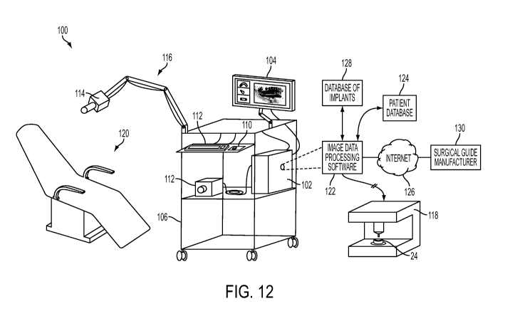
[0055] FIG. 12 is a hybrid diagrammatic view of a chair-side portable 3-
dimensional
scanning and image overlay system in communication with various data sources
and a
stereolithography machine, in accordance with the present invention;
[0056] FIG. 13 is a side perspective view of a dental implant supported
between a radiolucent
plate and a radiolucent upper support for use in scanning the dental implant
for obtaining a 3-
dimensional image thereof;
[0057] FIG. 14 is a side perspective view of a portion of a human spine
having two surgically
fused discs, and with pedicle screws driven into the adjacent fused discs, the
screws being
joined together by respective stabilizer rods;
[0058] FIG. 15 is a screen capture showing, at right, a 3-dimensional
superimposed pedicle
screw placement in a human spine (taken from behind), and with a 2-dimensional
axial view
of one of the superimposed pins shown at top-left, a 2-dimensional oblique
side view of the
superimposed pin shown at middle-left, and a 2-dimensional oblique top view of
the
superimposed pin shown at bottom-left;
[0059] FIG. 16 is another screen capture, similar to that of FIG. 15,
showing 3-dimensional
and 2-dimenaional views of a superimposed pedicle screw placement in a human
spine;
[0060] FIG. 17 is a screen capture showing a 3-dimensional rear
perspective view of the
exposed portions of pedicle screws placed in respective vertebrae the spine;
[0061] FIG. 18 is a screen capture showing a semi-transparent 3-
dimensional rear perspective
corresponding to FIG. 17, and showing the full pedicle screws relative to
internal spine
tissues; and
[0062] FIG. 19 is a top sectional view of a portion of a human torso in
which a spine surgical
guide has been attached to a vertebra for use in installing markers in the
vertebra.
DESCRIPTION OF THE PREFERRED EMBODIMENTS
[0063] The systems and image-overlay techniques of the present invention
include devices
and methods used to determine the precise anatomical position of surgical
implants or
prostheses, as well as osteotomies or other modifications to body tissues. 3-
dimensional
volumetric rendering software of pre-surgical patient DICOM (Digital Imaging
and
Communications in Medicine) image files are superimposed with either DICOM
images of
physical models or optical (such as laser) scans of patient anatomy or models,
or negative
DICOM images of an impression of the patient's anatomy, to accurately reveal
precise
anatomical or potential anatomical implant positions. The image-overlay
techniques allow a
-11-
CA 02862369 2014-06-27
WO 2013/102190
PCT/US2012/072270
clinician to fabricate, evaluate, and confirm accuracy of a surgical guide
using computed
tomography ("CT") scanning, cone beam computed tomography ("CBCT"), laser
scanning, or
the like, prior to or during placement of a dental implant (or other surgical
implant).
[0064] In accordance with current suggested radiologic guidelines of the
ALARA principle,
which is a system for limiting the radiation doses received by patients that
is recommended
by the International Commission on Radiological Protection (ICRP), the image-
overlay
systems and techniques described herein can significantly reduce patient
exposure to
radiation during and immediately after surgical procedures, without
compromising diagnostic
quality. It will be appreciated that the systems and techniques of this
invention have other
applications in dentistry and orthopedic reconstruction, and may be used, for
example, in
reconstructive surgery, lateral orbital decompression in ophthalmology,
substantially any
osteotomy or osteoplasty, veterinary surgical procedures, other medical
procedures that
involve altering (such as cutting or drilling) body tissues and/or placement
of prostheses,
implants, or the like, and for assisting in the orientation and alignment of
radiographic
devices, such as during oncological procedures.
[0065] The image-overlay techniques of the present invention limit a
patient's exposure to
radiation (particularly ionizing radiation) due to radiographic scanning, such
as X-rays, CT-
scans, CBCT-scans, and the like, while facilitating significant reduction in
the time and the
cost of fabricating a drilling or surgical guide, where desired, and enabling
personnel at a
medical office (such as a dental office) to prepare such guides in-house if
they so choose.
The systems, techniques and methods described herein can also improve the
accuracy of the
finished surgical guide and allow a dentist or surgeon or other medical
professional to
visually confirm that a hole (e.g., an osteotomy) drilled through the surgical
guide will be in
the proper location and in the correct alignment in the patient's jaw (upper
or lower mandible)
or other part of the body. Systems and methods are also provided for
evaluating the position
of an osteotomy or a marker in the patient's tissue, without the use of
ionizing radiation.
[0066] As will be more fully appreciated with reference to the more
detailed descriptions
below, the image-overlay techniques can be implemented before surgery, during
the process
of placement of dental implants (or other surgical implants), and/or after
surgical placement
of dental implants (or other surgical implants). One application or benefit of
the image-
overlay techniques is the ability to create "CT-confirmed" in-office surgical
guides, as will be
described below. Other applications of the image-overlay techniques include
mid-surgical
and/or post-surgical evaluation procedures, which are described herein as a
"pick-up
technique" or laser-scanning corollary technique.
-12-
CA 02862369 2014-06-27
WO 2013/102190
PCT/US2012/072270
[0067] The techniques of the present invention may be used for evaluating
the accuracy of a
surgical guide, and/or for fabricating a surgical guide, for use in drilling
an osteotomy in a
dental patient's jaw that is receive a dental implant such as a false tooth.
In referring to the
appended drawings, it will be appreciated that the same reference numeral is
generally used
for a particular part of the anatomy or other device regardless of whether it
is shown as a
display image of the actual anatomical part, or as a representative image of a
physical model
or a scan of the model. Thus, for example, a tooth is designated with
reference numeral 26
whether it appears as the CT-scanned image of a tooth (FIG. 1), or as the
plaster cast of a
tooth (FIG. 2).
[0068] Regardless of the medical procedure that is underway or is being
planned, the initial
step of the image-overlay techniques of the present invention is typically the
acquisition of an
accurate diagnostic CBCT/CT-generated 3-dimensional DICOM (or other digital
format)
image file of the relevant anatomical portion of the patient, such as shown in
FIGS. 1, 4A,
and 4B, which is usually accomplished prior to any cutting or drilling of the
patient's tissues,
such as for placement of a dental (or other surgical) implant.
[0069] In one form, the technique is applicable to a dental implant
procedure that generally
follows these steps:
1) The dental professional captures a 3-dimensional CBCT-scan or CT-scan
image 20 of the patient's jaw area 22 in need of a dental implant, such as
shown in FIG. 1 and the non-stippled portions of FIG. 4A.
2) A physical model 24 or "diagnostic cast" or "wax up" (FIG. 2) is made of
the
patient's teeth 26 and gums 28 in the same area as CT-scan 20, to determine
implant placement based on ideal restorative position. This model 24 can be
fabricated with rapid-prototyping methods based on the CT-scan data, or
based on a laser scan of the patient's teeth and gums, or can be fabricated as
a
cast (e.g. a plaster cast) taken from a mold of the patient's teeth 26 and
gums
28, for example.
3) Based on the dental professional's knowledge of the location of the
patient's
jawbone 30, relative to the patient's teeth 26 and gums 28, based on a study
of
the tissues shown in the initial CT-scan of FIG. 1, the professional drills
one or
more holes 32 or "osteotomies" in the model or cast 24 (FIG. 2) in the desired
-13-
CA 02862369 2014-06-27
WO 2013/102190 PCT/US2012/072270
3-dimensional position (including the buccal-lingual position, mesial-distal
position, and angle of insertion) for each dental implant. This drilling may
be
done free-hand, or may be performed using a drilling guide (or "surgical
guide") 34, such as shown in FIG. 5. The holes 32 are drilled in the model or
cast 24 to the desired final diameter and depth, such as shown in FIG. 2. It
will be appreciated that the final depth of each osteotomy 32 will vary due to
tissue thickness, and is determined based on an image-overlay step that will
be
described below. At this point in the process, the clinician has a model with
a
hole (a simulated osteotomy) drilled in the physical model to the desired
implant diameter and length for each proposed osteotomy.
4) The drilled hole in the model is then filled with a radiopaque marker 36
(FIG.
3), which may be a dental filling material (composite), barium sulfate acrylic
monomer, a metallic stud or pin or drill bit, or the like.
5) Another 3-dimensional CBCT-scan or CT-scan is made of the model/cast 24
(not of the patient), in which the radiopaque marker 36 in the drilled hole 32
is
clearly visible in the image generated by this scan of the model/cast 24.
Except for the presence of a radiopaque material-filled hole 32 and the lack
of
internal anatomical detail, the image produced by this second radiographic
scan (of the model/cast) will be substantially identical to the image 20
produced by the first scan (of the patient's actual jaw area), because the
surfaces of the model/cast are substantially identical to the surfaces of the
patient's actual jaw area.
6) A software program is used to digitally overlay the second scan with the
first
to form a composite image 38 (FIGS. 4A and 4B). The first CT-scan image
(of the patient's anatomy, having smooth grey surfaces in FIG. 4A) and second
CT-scan image (of the model 24, having stippled surfaces at right in FIG. 4A)
can be precisely aligned with one another on-screen, because the patient's
anatomy will be substantially identical in each of the overlaid images, which
are set at a 1:1 size scale. However, the radiopaque material-filled hole 32
from the second scan will appear superimposed in the patient's jaw, such as
best shown along the left side portion of FIG. 4A (i.e., front sectional view
-14-
CA 02862369 2014-06-27
WO 2013/102190
PCT/US2012/072270
38a, side sectional view 38b, and top sectional view 38c). A similar second
scan image may be produced by implanting a surgical implant 126 in the
model 24 and using it as a radiopaque marker 36, such as shown in FIG. 4B.
In the overlaying or superimposition step, the patient DICOM images (first
scan) and the prepared and working cast images (second scan) may be
superimposed in precise alignment by aligning anatomical landmarks or
fiducial markers, such as for procedures involving soft-tissue-borne surgical
guides. Optionally, superimposed cross-hairs 48 and length measurement
scales 50 may be shown on the sectional views 38a-c (FIG. 4B) to aid the
clinician in determining placement and orientation of the radiopaque marker
36 in the model 24, relative to the patient's internal tissues shown in the
initial
radiographic scan image. Suitable software programs for performing image
overlays may include Invivo software, available from Anatomage Inc., of San
Jose, CA.
7) Once the 3-dimensional composite image is set with proper alignment,
the
dental professional or other technician can manipulate the composite images
of FIGS. 4A and 4B on-screen, to view them from substantially any desired
angle or perspective, such as coronal (front) plane view 38a, sagittal (side)
plane view 38b, and axial (top) plane view 38c, such as shown along the left
side portions of the images as shown in FIGS. 4A and 4B. These views reveal
the planned anatomical path of the implant, but typically do not account for
the thickness of the exposed or outer soft tissue architecture, such as gums,
which would affect osteotomy depth but not the drilling orientation or path.
Because the hole (simulated osteotomy) in the model 24 is filled with a
radiopaque marker 36 (FIG. 3), the contrast and brightness of the 3-
dimensional volumetric images can be adjusted to distinguish the radiopaque
marker 36 (or "virtual implant") from the material of the model 24 and the
underlying anatomy visible in the pre-surgical patient CBCT or CT scan. The
image of the radiopaque marker 36 contrasts the anatomical structures of the
patient (i.e.: teeth, bone, major nerve bundles, sinuses, or other necessary
landmarks of concern) in the composite images of FIGS. 4A and 4B, and
allows diagnostic assessment of the proposed implant placement and analysis
of a fabricated surgical guide. Thus, the dental professional can use the
-15-
CA 02862369 2014-06-27
WO 2013/102190
PCT/US2012/072270
composite image 38 to determine whether a given surgical guide 34 will
provide proper alignment for a proposed drill hole made using the guide 34, or
to determine whether the drilled hole 32 in the model 24 is in the desired
location, as will be described in more detail below.
8) If the drilled hole 32 in the model 24 is found to be satisfactory based
on the
composite overlay image 38, and was made without the benefit of a surgical
guide, a new surgical guide 34 can be made from the model/cast 24, such as
shown in FIGS. 5-7B. To produce the surgical guide 34, at least a portion of
the radiopaque marker is removed from model 24, such as by drilling a pilot
hole 40 into the center of the radiopaque marker 36 (FIG. 6), inserting a
guide
element 42 (such as an insert handle, a sleeve, an indexing pin, or a stud) in
the pilot hole 40. As shown in FIG. 7A, an upper end portion 42a of the guide
element 42 projects outwardly from the pilot hole 40 and can be used to
precisely position a surgical guide hole 44 that may be lined with a metal
ring
46 in surgical guide 34, which is typically made of a resinous plastic
material
that is heated and conformed over the representative teeth 26 of the
model/cast
24 by applying downward pressure, as is known in the art.
9) The surgical guide 34 may then be placed over the patient's teeth
(similar to its
placement on model 24, as shown in FIG. 5), and the surgical guide hole 46
will be at the precise location and alignment so that an osteotomy drilled
through the guide hole 44 in the surgical guide 34 and into the patient's jaw
bone, will be in substantially the identical location in which the radiopaque
marker 36 appeared in the composite image 38. The drilling of the osteotomy
through the surgical guide 34 may typically involve the use of a surgical
guide
tool 43 that is seated in the guide hole 46 for aligning a drill 52, such as
shown
in FIG. 7B.
[0070]
As briefly noted above, a similar technique may be used to evaluate the
accuracy of
an existing surgical guide 34, whether that guide has been made using the
technique(s)
described herein, or by other methods. The surgical guide 34 is fitted to the
model/cast 24 of
the patient's teeth, and a hole 32 (simulated osteotomy) is drilled into the
cast or model 24
using the surgical guide 34. The hole 32 is filled with radiopaque marker 36,
scanned, and
-16-
CA 02862369 2014-06-27
WO 2013/102190
PCT/US2012/072270
the resulting image is overlaid with the original patient CT scan in
substantially the same
manner as described above. It will be appreciated that substantially any
surgical guide can be
evaluated for accuracy prior to surgery using the techniques describe herein.
For example, if
a clinician fabricates an in-office surgical guide or orders a commercially-
prepared surgical
guide, and desires to test the accuracy of that guide, the clinician may
repeat the pre-surgical
phase of the technique on a duplicate model with a new radiopaque marker to
assess the
precision and accuracy of the surgical guide. When the clinician is satisfied
with the virtual
implant (radiopaque marker) position provided by the image-overlay technique,
the surgical
guide may be sterilized and then used during surgery on the patient.
[0071] As described above, one pre-surgical benefit of the image-overlay
techniques of the
present invention is the ability to fabricate an accurate in-office "CT-
confirmed" surgical
guide, while another benefit is to permit or facilitate confirmation of the
accuracy of
substantially any surgical guide regardless of its fabrication method.
Although there are
differences in preparation, the outcomes and benefits of producing pre-surgery
"CT-
confirmed" surgical guides are substantially similar. By employing the image-
overlay
technique and reviewing the results, if a commercially-prepared surgical guide
is deemed
acceptable to the clinician, the image-overlay technique provides a means to
"CT-confirm"
the precision of substantially any fabricated surgical guide.
[0072] Different manufacturers of surgical drilling systems typically
utilize a different "V-
factor" for their surgical drills or "burs" (i.e., defining the portion of the
bur that is included in
dimensional calculations provided by the bur manufacturer), which should be
taken into
consideration during implant placement. When osteotomy depth is a concern,
such as due to
encroachment upon a "safety zone" of an adjacent vital anatomical internal
structure (such as
neurovascular bundle, maxillary sinus, or cortical plate perforation), the use
of optional
techniques (such as the "pick-up technique" or its laser-scanning corollary,
described below),
may be more appropriate. Such techniques facilitate the avoidance of errors
during the
surgical phase of treatment, which may be particularly challenging to address
and correct.
Therefore, the use of techniques and systems that facilitate a dental
professional's ability to
quickly and accurately assess osteotomy preparation and final implant position
can be very
important.
Pick-Up Technique
[00731 Optionally, a dental professional may take steps to further ensure
proper location of a
hole (osteotomy) that is drilled into the patient's jaw 30, by using a "pick-
up" technique that
-17-
CA 02862369 2014-06-27
WO 2013/102190
PCT/US2012/072270
involves placing a stud in an initial pilot hole drilled in the jaw (similar
to pilot hole 40
drilled in model 24, such as shown in FIG. 6), and taking an impression of the
region during
the surgical procedure of placing the insert or prosthesis. When the
impression material cures
in the patient's mouth and is removed, the stud stays in the impression
material and thus is
removed ("picked up") from the pilot hole formed in the patient's jawbone. The
impression
material is then used to make a cast or model (such as a plaster cast), and
the cast will include
the stud (or a drilled hole filled with a radiopaque marker representing the
stud). The cast is
then scanned to create a 3-dimensional image that is overlaid with the
original 3-dimensional
patient scan (showing internal tissues) to verify whether the pilot hole in
the patient's jaw is
placed in the desired location and orientation. It will be appreciated that
the making and
scanning of a cast or other physical model with the stud is optional, since
the impression
itself could be scanned and viewed as a negative, which would result in an
image that is the
equivalent of a scanned image of a "positive" mold or model made from the
"negative"
impression of the patient's anatomy.
[0074] Regardless of whether the clinician has a "CT-confirmed" surgical
guide, a traditional
CT-guided surgical guide, or an in-office fabricated surgical guide, the pick-
up technique (or
its laser-scanning corollary technique, described below) is useful for
avoiding multiple scans
of the patient using ionizing radiation. Using the image-overlay techniques
described herein,
a modified indexing pin or any other marker or object that can be captured or
partially
encapsulated in a pick-up impression (or that is capable of being optically
distinguished by a
3-dimensional laser scanner), during or after surgery, can serve as a useful
diagnostic adjunct.
A captured indexing pin or analog for each osteotomy (or an implant or implant
abutment, if
the impression is taken post-placement) is partially encapsulated in the
impression material,
in the location that accurately represents the location of the pin, implant,
marker or analog in
the patient's anatomical tissue. At this point, based on time and availability
of access to a
CBCT or CT scan, the clinician can evaluate a negative image of the impression
superimposed with the pre-surgical scan, or can pour a model of the impression
and perform
a scan followed by the same type of superimposition steps described above.
However, it will
be appreciated that laser scanning of the area of the patient undergoing
surgery can be used in
place of a pick-up impression, with image extrapolation techniques used to
indicate the depth
and orientation at which the indexing pin (or other object positioned in the
osteotomy to serve
as a marker) extends into the patient's tissue (such as jaw bone).
[0075] Accordingly, the pick-up technique (and the laser-scanning
corollary technique
described below) allows for precise evaluation of multiple implant placements
at the same
-18-
CA 02862369 2014-06-27
WO 2013/102190
PCT/US2012/072270
time during surgery, without relying on 2-dimensional representations of
implant placements
from periapical or panoramic films. When the clinician uses the pick-up
technique during the
early stages of osteotomy preparation, errors in angulations, depths or
location can be
identified early and adjustments can be made, typically without compromising
treatment
outcomes. It will be appreciated that use of a pick-up impression or laser
scan of the patient's
anatomy during surgery can result in the patient having no additional exposure
to
radiographic scans such as X-ray, CT scan, CBCT scan, or other ionizing
radiation during or
immediately after surgery, while still permitting a mid-surgical assessment of
the placement
of multiple implants. Thus, the pick-up technique or its laser-scan corollary
(described
below) provides a beneficial clinical procedure that follows the
recommendations of the
ALARA principle by offering a significant advancement compared to existing
surgical and
radiologic protocols.
Laser-Scanning Corollary to Pick-Up Technique
[0076] The laser-scanning technique permits evaluation of the position of
a marker (e.g., an
implant or screw) position in 3 dimensions, during or after surgery, with no
ionizing radiation
exposure to the patient or surgical staff, and without the use of an
impression of the patient
anatomy. Like the above-described pick-up technique, the laser-scanning
technique reduces
or eliminates the need for the use of mid-surgical or immediate post-surgical
X-ray images to
evaluate single or multiple implant or surgical fixation screws. Although
primarily described
herein as a "laser scanning" technique, it will be appreciated that
substantially any optical or
non-radiographic scanning technique may be used, as long as it is capable of
generating 3-
dimensional digital images of the outer or exposed surfaces of an anatomical
portion of the
patient, such as teeth, gums, skin, or internal tissues (e.g., bone, muscle,
tendons, cartilage,
blood vessels) that are exposed during a surgical operation.
[0077] The basic steps of the laser-scanning technique are illustrated
diagrammatically in
FIG. 8 and described immediately below, while a more detailed description of
the technique
will follow. The laser-scanning technique involves a double superimposition
process in
which three or more 3-dimensional digital images are obtained and combined in
stages. A.
Initially, a pre-operative DICOM (or other digital format) 3-dimensional image
is obtained
(FIG. 8, at 'A'), typically via X-ray scan, CT scan, CBCT scan, MRI scan, or
other (typically
radiographic) imaging method. A surgical procedure is then performed by
medical personnel
to install one or more markers in the patient anatomy, or an analog procedure
is performed on
an accurate model (such as a plaster cast) of the anatomical region of the
patient, such as
-19-
CA 02862369 2014-06-27
WO 2013/102190
PCT/US2012/072270
shown in FIG. 8 at 'B', in which three surgical markers have been inserted
into respective
holes formed or established in a model of the patient jaw portion. An optical
(e.g., laser) or
non-radiographic scanned image (FIG. 8, at 'C'), such as a laser Virtual
Surface Anatomy
Scan Image (such as in a stereolithography or "STL" 3-dimensional image
format), is made
of the outer or exposed anatomical surfaces of the patient (or of the model
corresponding to
the patient anatomy), including exposed portions of any markers present. The
markers may
be substantially any object (e.g., a pin, a drill, an implant, a surgical
guide or appliance
having a fiducial marker, or a screw) that is capable of being optically or
non-
radiographically scanned by an electronic image scanning device, and that is
visually
differentiable from surrounding tissues or other surfaces. The resulting 3-
dimensional laser-
scanned image is represented by stippled surfaces in FIG. 8 at 'C', 'D', and
'F' through 'I'.
[0078] The pre-operative image of the patient anatomy (shown in FIG. 8 at
'A' and
represented by non-stippled surfaces in FIG. 8 at 'D', 'H', and 'I') and the
laser-scanned image
(represented by stippled surfaces in FIG. 8) are converted to compatible
digital image formats
(e.g., STL or DICOM) if necessary, and are combined or superimposed or
overlaid and
aligned with one another to form a first composite image (FIG. 8, at 'D'). The
alignment step
resulting in the image of FIG. 8 at 'D' may be facilitated with reference to
one or more cross
sectional views, such as the coronal cross-section view of FIG. 9A in which
the laser-scanned
surface image (hollow outline in FIG. 9A) is overlaid with the pre-surgical
CBCT scan
(stippled in FIG. 9A) at a corresponding portion of the patient jaw. Once the
laser-scanned
image of FIG. 8 at 'C' is obtained, digital images of the corresponding one or
more markers
(FIG. 8, at 'E') may be superimposed therewith to create another composite
image (FIG. 8 at
'F'). In the composite image of FIG. 8 at 'F', the non-stippled images of the
entire markers are
initially misaligned with the exposed proximal or upper end portions of the
markers (stippled)
of the laser-scanned image. However, it will be appreciated that the lower
portions of the
entire markers (non-stippled) may be obscured by the laser-scanned image at
this stage, as
shown in FIG. 8 at 'F'. The technician can then individually manipulate the
image of each
entire marker on-screen to achieve proper alignment of its upper exposed end
portion with the
upper exposed end portion of its match in the (stippled) laser-scanned image,
such as shown
in FIG. 8 at 'G', in which stippled and non-stippled image portions are
visibly intermingled.
[0079] At this stage in the image overlay and evaluation process, two
aligned composite
images have now been prepared, the first composite image being that of FIG. 8
at 'D' in
which the laser-scanned outer surfaces of the patient anatomy are overlaid and
aligned with
the pre-operative image, and the second composite image being that of FIG. 8
at 'G' in which
-20-
CA 02862369 2014-06-27
WO 2013/102190
PCT/US2012/072270
the entire marker images are overlaid and aligned with the exposed portions of
the markers
appearing in the laser-scanned image. These two composite images may now be
combined or
overlaid or superimposed with one another to form a third composite image
(FIG. 8 at 'H'), in
which the properly-aligned markers are shown with the laser-scanned image of
the exposed
anatomical surfaces, which are aligned with the radiographically-scanned image
of the same
region. For clarity of illustration, the radiographically-scanned image and
the laser-scanned
image have been shown as opaque where they appear in the drawings of FIG. 8 at
'A' and at
'C' through 'H'. However, it will be appreciated that these images may be
readily made at
least partially translucent, such as shown in FIG. 8 at 'I', which would
include a depiction of
internal tissues (not shown in FIG. 8) in the case of the radiographically-
scanned image, so
that the technician or medical professional can visually verify or study the
location of the
lower or distal (embedded) portion of each marker relative to those internal
tissues, for
evaluative purposes. The resulting double-superimposed composite image of FIG.
8 at 'I'
reveals accurate bony anatomy, soft tissue anatomy, and marker (drill,
implant, stud, etc.)
positions relative to those tissues, without the use of multiple radiographic
scans of the
patient, and without taking an impression of the patient's jaw portion or
other anatomical
region. Optionally, 2-dimensional cross sectional views may be generated along
different
planes in the 3-dimensional images of FIG. 8 at 'H' and 'I', such as shown in
FIGS. 9B and
9C.
[0080] It is envisioned that the order of at least some of the steps may
be altered from the
manner in which they are described above, and that the steps themselves may be
altered to
some degree, without departing from the spirit and scope of the present
invention. For
example, the 3-dimensional images of the entire markers, as shown in FIG. 8 at
'E', could be
overlaid or superimposed directly into the first composite image of FIG. 8 at
'D', to arrive at
substantially the identical third composite image of FIG. 8 at 'H' (and, thus,
of the
corresponding translucent image of FIG. 8 at 'I'), without need for a separate
step of
generating the composite image of FIG. 8 at 'G', in which the entire marker
images are
overlaid and aligned with the exposed portions of the markers appearing in the
laser-scanned
image.
[0081] The laser scan described above results in a 3-dimensional digital
image showing only
the outer or exposed surfaces of the scanned anatomical portion of the
patient, such as the
patient's jaw area, including gums and teeth, with the stud or implant
(marker) positioned in
the pilot hole or in a final osteotomy, such as shown in FIG. 8 at 'C' and in
FIG. 10A. The
marker's dimensions are known from manufacturer data or from scanning the stud
itself prior
-21-
CA 02862369 2014-06-27
WO 2013/102190
PCT/US2012/072270
to its implantation and, preferably, a 3-dimensional image is available (or
obtainable through
scanning), which depicts the outer surfaces of substantially the entire
marker. If 3-
dimensional marker images are not available from the manufacturer of the
marker or another
source, such images may be obtained using an optical scanner (such as the same
laser scanner
that is used to generate images of the exposed surfaces of the patient
anatomy) to create an
STL or DICOM format (or other format) image of the marker(s) to be used during
the
medical procedures. Optionally, it is desirable to create a library of 3-
dimensional images of
an assortment of different markers that are readily available for access by a
computer used in
the image-overlay process. This may be particularly helpful, for example, when
the type of
marker being used is changed during the surgical process.
[0082] As described above, the dimensions or 3-dimensional images of the
marker(s) (FIG. 8
at 'E') allow a technician to create an overlaid or composite image that
accurately represents
the depth and orientation of each marker's lower or distal portion (which is
inserted into the
osteotomy in the patient's jaw) relative to the patient's internal anatomical
tissues, such as
shown in FIGS. 10B-10C and 11B-11C. This is typically accomplished by
overlaying and
aligning the upper portion of the 3-dimensional image of substantially the
entire marker with
the upper portion of the marker that is exposed above the gum line in the
laser-scanned
image. The image of the lower (distal) portion of the marker thus projects or
is extrapolated
below the exposed tissue surfaces that were scanned by the laser scanner, such
as shown in
FIGS. 8 at 'I' and 10B. The laser scanned image with the overlaid image of the
entire stud
can then be overlaid with the original CT scan of the patient's jaw area,
showing internal
tissues such as bone and nerves (e.g., FIGS. 10C, 11B, and 11C), so that the
dental
professional can visually verify whether the osteotomy in the patient's jaw
has been drilled at
an appropriate orientation and depth, with the resulting composite image being
viewable from
substantially any desired angle for viewing from different vantage points.
[0083] Surgical drills or other surgical instruments (indexing pins, etc.)
with known
dimensions and shapes can also be used as markers and captured in the laser-
scanned image
of the patient's exposed anatomical surfaces, and extrapolated as described
above, as long as
there is a digital image of the drill or instrument being used as a marker.
The markers used in
the image overlay techniques are preferably rigid or substantially rigid so
that the markers
cannot be flexed or otherwise distorted during normal use, in order to
facilitate the image
overlay techniques described herein.
-22-
CA 02862369 2014-06-27
WO 2013/102190
PCT/US2012/072270
[0084] The laser-scanning technique will now be described in more detail,
including optional
steps. In a pre-surgical or initial phase of medical procedure in which
overlay imaging is to
be used, the following steps may be followed:
(1) A 3-dimensional image of the relevant patient anatomy (e.g., a CT,
CBCT,
MRI, other equivalent diagnostic image) is obtained, such as shown in FIG. 8
at 'A', but with internal tissues made visible as needed;
(2) the ideal or desired placements of implants, screws, or other medical
devices
are planned based on a pre-surgical plan;
(3) a physical model is made of the patient anatomy, such as by pouring a
cast of
an impression, or by stereolithography or other rapid-prototyping technique;
(4) the marker(s) are installed in the model (FIG. 8 at 'B'), according to
the pre-
surgical plan;
(5) the model with marker(s) installed is scanned with a laser scanner (or
equivalent scanner using non-ionizing radiation) to create a Virtual Surface
Anatomy Scan (3-dimensional image) that includes the model representation
of the skin or gums, the surgical marker(s), and teeth, such as shown in FIG.
8
at 'C', prior to any surgery on the patient;
(6) a 3-dimensional image of the entire marker (which may be a pin, drill,
an
implant and/or related components, a screw, etc.) is created or obtained from
another source (FIG. 8 at 'E');
(7) the 3-dimensional image of the entire marker (or markers) is overlaid
and
aligned with the Virtual Surface Anatomy Scan (FIG. 8 at 'F' and 'G');
(8) a composite image is created by superimposing the original 3-
dimensional
patient image with the Virtual Surface Anatomy Scan (FIG. 8 at 'D');
(9) a final composite image of the original 3-dimensional patient image,
the
Virtual Surface Anatomy Scan, and the 3-dimensional image of the entire
marker(s) is created (FIG. 8 at 'H' and 'I'); and
-23-
CA 02862369 2014-06-27
WO 2013/102190
PCT/US2012/072270
(10) the medical professional evaluates the final composite image to determine
where the markers, which at this point are positioned only in the physical
model of the patient's anatomy, would lie relative to the internal tissues of
the
patient's anatomy, if they were attached to the patient in precisely the same
manner in which they are attached to the model.
(6) Optionally, a surgical guide may be fabricated at the model,
such as in a
manner described above, or obtained from another source, if a surgical guide
is desired for use during the surgical phase of the procedure.
[0085] In the surgical or mid-operative phase of the laser-scanning
technique, the following
steps are generally followed:
(1) Optionally, a surgical guide with fiducial markers (i.e.,
distinguishable
"landmarks" that can be used as an alignment aid) is placed on the patient
anatomy to aid in superimposition (e.g., for edentulous cases);
(2) surgery is performed as usual according to the individual surgeon's
preferences;
(3) any time a mid-surgery evaluation is desired, a laser scan (or
equivalent scan
using non-ionizing radiation) is taken of the exposed anatomical surfaces and
any markers in the surgery area, such as shown in FIGS. 10A and 11A, to
create a Virtual Surface Anatomy Scan that results in an image showing
patient skin or gums, the surgical guide(s) or marker(s) present, and teeth,
such as shown in FIGS. 10A and 11A, and similar to what is shown in FIG. 8
at 'C' (which is actually a laser-scanned image of the surfaces of a model
corresponding to the patient anatomy);
(4) the 3-dimensional image(s) of the entire marker(s) (which may be any
sufficiently rigid drill, implant, screw, or pin of substantially any shape)
are
superimposed and aligned with the protruding portions of the marker(s) visible
in the mid-surgery laser scan, and evaluated for desired placement of the
marker(s) in the composite image that includes the interior tissues shown in
the pre-surgical image, such as shown in FIGS. 10C and 11C;
-24-
CA 02862369 2014-06-27
WO 2013/102190
PCT/US2012/072270
(5) optionally, the alignment of the Virtual Surface Anatomy Scan with the
pre-
surgical image may be accomplished with reference to overlaid cross-sections
of the images, such as shown in FIGS. 9A-9C;
(6) optionally, the surgeon may make changes at the surgical site based on
information obtained from the composite image(s) in the preceding step(s);
(7) optionally, additional optical scans are made of the surgical site
until the
surgical procedure is complete; and
(8) optionally, post-operative optical scans and overlays are used to
confirm that
the final implanted device(s) is/are in the desired locations and
orientations,
such as shown in FIGS. 10B, 10C, 11B, and 11C.
Additional Considerations
[0086] It will be appreciated that both the pick-up technique and its
laser-scanning corollary
can be used to place multiple studs, implants, or markers in a patient's jaw
during the same
overall procedure, and may be accomplished while the patient undergoes a
single dental or
other medical procedure, rather than during multiple procedures spaced out
over several days
or weeks. As noted above, and as will be more fully appreciated with reference
to additional
descriptions provided below, these procedures may be used not just in dental
procedures, but
in substantially any medical procedure in which an implant or prosthesis is to
be attached to
human tissue, particularly bone. However, it is envisioned that the technique
could also be
used in connection with softer tissues like cartilage or any other tissue that
can be
distinguished on CT, MRI or equivalent 3-dimensional imaging.
[0087] It will also be appreciated that the image-overlay techniques of
the present invention
depend at least somewhat on (i) a medical professional's (or imaging
technician's) ability to
successfully and accurately superimpose 3-dimensional volumetric rendered data
for implant
placement, (ii) discrepancies between the depth of the virtual dental implant
placement (e.g.,
in a physical model) and final implant position in the patient anatomy, and
(iii) the time
required during mid-surgery to evaluate a superimposition during execution of
the pick-up
technique, for example.
[0088] The ability to successfully superimpose 3-dimensional volumetric
rendered data
accurately may warrant additional attention in totally edentulous cases
(patients without any
teeth), for example, as it may be desirable for a radiopaque stent (or a guide
with radiopaque
-25-
CA 02862369 2014-06-27
WO 2013/102190
PCT/US2012/072270
fiducial markers) to be worn by the patient, during the original radiographic
scan. However,
as long as the original scan utilizes a radiopaque stent or the like, the
accuracy of the image
overlay techniques should remain substantially the same as for cases in which
there are
natural fiducial markers or landmarks (e.g., teeth) present. A duplicate
denture with barium
sulfate acrylic monomer (or the like) with fiducial markers, which can be
superimposed after
the osteotomies are drilled, may also be helpful for superimposition. The
replication of tooth-
borne surgical guides can be facilitated by taking precautions to reduce the
amount of scatter
radiation, and the teeth may be separated so that superimposition of the
dentition (teeth
arrangement) is possible.
[0089] The potential for discrepancies between the depths of the virtual
implant (e.g., in a
physical model, or a pilot hole or osteotomy in a patient's anatomy) and final
implant position
in the patient anatomy can be readily addressed. While the thickness of a
surgical guide may
be negligible with respect to predicted implant placement, it is desirable for
a clinician to be
aware of necessary anatomical considerations and have knowledge of the
surgical system
used to accurately approximate osteotomy depth during surgery. The pick-up
technique (or
its laser scanning corollary) provides the clinician with the ability to
accurately assess the
state of surgery for multiple implants, if necessary. While conventional
periapical films
could assist the clinician with depth approximation, the pick-up technique or
laser scanning
corollary described herein may be used for determining the depth of a given
osteotomy
without the use of ionizing radiation or other radiographic imaging.
[0090] During mid-surgery, the time required to take a pick-up impression
(or laser scan of
the patient's mouth portion), create a DICOM image, superimpose the pre-
surgical and pick-
up impression image (or 3-dimensional laser image), and then perform
evaluation, may be a
concern. However, it is envisioned that the time expended by a clinician to
address failed
implant placement post-surgery would typically be considerably greater than
using the pick-
up technique (or laser scanning corollary) to verify placement during surgery.
This can be
addressed, for example, by immediately using the pick-up impression to create
a negative
DICOM image, or by using a laser-scanning method to create an image model of
the surgery
area. In the case of creating a negative DICOM image, imaging software should
be capable
of superimposing a negative DICOM image and an original patient scan. The
faster
processes may utilize, for example, a macro or micro CT unit or 3-dimensional
high
definition (HD) laser scanner that is portable, cost effective, and provides
substantially
immediate or automatic superimposition without manual superimposition of DICOM
images,
such as will be described below in more detail.
-26-
CA 02862369 2014-06-27
WO 2013/102190
PCT/US2012/072270
[0091] As previously mentioned, the image-overlay techniques of the
present invention are
equally applicable to other areas of dentistry and medical surgery. For
example, the pick-up
technique and its laser-scanning corollary technique can permit clinicians to
accurately assess
placements of temporary anchorage devices in orthodontics and post placement
for
endodontically-treated teeth in restorative dentistry. It is possible that
obturation or
endodontic materials could be captured in a pick-up impression and
superimposed to also
confirm accuracy. By further example, airway volumes can be visualized using
these
methods, with superimposition used to determine the effect of dental sleep
appliances. The
techniques may also be used by orthopedic surgeons, such as for knee, hip, or
other long bone
reconstructions, if adequate pre-surgical images are taken prior to surgery.
It will be
appreciated that modifications may be needed to accurately utilize the pick-up
impression
technique in non-dental environments, particularly those in which natural
fiducial markers
(such as teeth) are not present, but in general the same overall methods would
be used outside
of a dental environment.
[0092] It is envisioned that the techniques described herein may also
benefit medical
professionals undergoing training and/or evaluation, by allowing clinicians to
be objectively
assessed during training and early surgical procedures. Accurate feedback and
evaluation of
clinical skill would be beneficial to students learning to place dental
implants, which could
result in reduced clinical failures, improved surgical outcomes, and reduced
radiation
exposure to patients.
[00931 Therefore, image-overlay techniques of the present invention can
improve the quality
of patient care with evidenced-based 3-dimensional evaluations of
substantially any surgical
guide, and can also provide a method or technique for obtaining immediate or
rapid
feedback/confirmation of the surgical placement of dental implants or the
like. While the use
of surgical guides improves the probability that desirable outcomes will be
achieved, these
outcomes are at least somewhat dependent on individual clinician skill levels
and judgment,
surgical conditions, available equipment, and different techniques, so that
mere use of a
surgical guide does not guarantee predictability or success. The image-overlay
techniques of
the present invention can help to reduce these variables and thus reduce
clinical failures,
improve surgical outcomes, and reduce radiation exposure to patients and
medical
professionals. Images similar to those obtainable using CT, CBCT, and MRI
equipment may
be obtained with greater speed and lower cost, and without the use of
additional ionizing
radiation, and the surgical techniques and surgical equipment used during
surgery need not be
-27-
CA 02862369 2014-06-27
WO 2013/102190
PCT/US2012/072270
altered in order to make use of the medical image evaluative techniques of the
present
invention.
System for Use in Image-Overlay Techniques
[0094] Referring now to FIG. 12, an image-overlay medical evaluation
system 100 includes a
computer 102 with associated display 104. In the illustrated embodiment, these
components
are supported or mounted on a portable cart 106, although it will be
appreciated that the
individual components of system 100 need not be supported together. A standard
keyboard
108 and mouse 110 or other controllers (e.g., a touch-screen) are in
communication with
computer 102 and mounted at a location on portable cart 106 (such as on a
tray, as shown) to
provide convenient access by a medical technician.
[0095] Computer 102 is in communication with several other peripheral
devices including a
macro CBCT scanner 112, a laser scanner 114 (shown coupled to cart 106 via an
articulated
arm 116), and a rapid prototyping machine 118 for producing diagnostic models
24. When
the image-overlay medical evaluation system 100 includes a portable cart 106
as shown, the
computer 102, display 104, keyboard 108, and mouse 110, macro CBCT scanner 112
and
laser scanner 114 may be transported together around a medical office, such as
for use
adjacent a dental or medical chair 120, while computer 102 may be in
communication with its
peripheral devices via wired or wireless connections.
[0096] Computer 102 operates a software package 122 for processing images
and data, and
for communicating images and data via wired or wireless connections (FIG. 12).
For
example, software 122 can be used by the medical clinician to operate macro
CBCT scanner
112 and laser scanner 114, and to manipulate, convert, and overlay images
collected by the
scanners 112, 114 on display 104. Since laser scanner 114 and macro CBCT
scanner 112
may produce images in different formats, it is desirable that software 122 be
capable of
converting one or more image formats into another one or more different
formats, so that the
images collected by different devices can be displayed together in an
overlying fashion, such
as in the manner described above. Suitable laser scanners capable of scanning
anatomical
surfaces may include, for example, those currently manufactured by Northern
Digital Inc.
("VicraScan") and Basis Software Inc. ("Surphaser"), as well as the Cadent
iTero intraoral
scanner, available from Align Technology, Inc. of Carlstadt, New Jersey, and
laser scanners
available from NextEngine, Inc. of Santa Monica, California. Suitable CBCT
scanners may
include, for example, those manufactured by Carl Zeiss Industrielle
Messtechnik GmbH
("METROTOM"), or the i-CAT scanner available from Imaging Sciences of
California.
-28-
CA 02862369 2014-06-27
WO 2013/102190
PCT/US2012/072270
Other devices that may be used for measuring dimensions include coordinate
measuring
machines (CMM's), such as those available from Hexagon Metrology, Inc. ("ROMER
Absolute Arm").
[0097] Thus, software 122 is configured to access, display, convert, and
manipulate digital
images in various formats including, for example, DICOM images, CAD images,
STL
images, or the like, such as may be generated by a digital laser scanner (e.g.
scanner 114) or
CBCT scanner (e.g., macro CBCT scanner 112). Software 122 permits a clinician
to review
digital images, visualize virtual models and create images overlays on display
114, and which
may be saved in a patient database 124. In addition, software 122 may be
operable to create
and transmit laboratory prescriptions, such as digital models of anatomical
features, to an
on-site or off-site laboratory for use in fabricating a prosthetic (e.g.,
partial dentures, implant
abutments, orthodontic appliances, and the like), surgical guides, or the
like. Software
capable of at least superimposing or overlaying images include Mimics
software, available
from Materialise NV of Leuven, Belgium, with image analysis facilitated by 3-
Matic
software, also available from Materialise NV.
[0098] Software 122 is in communication with patient database 124 (FIG.
12), which
includes a collection of images (e.g., 3-dimensional or 2-dimensional images
of patient
anatomy, of models of patient anatomy, photographs, etc.) as well as
substantially any other
information relevant to a given medical patient (medical records, identifying
information,
etc.). Patient database 124 includes digital electronic archives of patient
dental records
including, for example, individual arch models, orthodontic appliances, dental
prostheses,
articulated models, and the like. Database 124 may reduce or eliminate the
need to store
physical diagnostic models, while facilitating access to digital images or
models to create a
stereo-lithographic model (or other rapid prototyping model) on an as-needed
basis. Patient
database 124 may be stored on a computer hard drive at computer 102, or may be
stored on a
remote drive, server, or the like, which may be located in or near the medical
office, or at an
offsite location, and accessed by computer 102 operating software 122 via
wired or wireless
communications. For example, patient database 124 may be administered by a
third party
service provider, and accessed and maintained via the Internet 126.
[0099] Optionally, software 122 may be in further communication with a
marker or implant
database 128 of medical implants and/or tools and/or prostheses (at least some
of which can
be used as markers), which includes dimensional information for a range of
medical implants,
tools, or the like, so that a properly-scaled rendition or image of a given
implant or tool may
be superimposed on the image(s) at display 104. Implant database 128 may
include a
-29-
CA 02862369 2014-06-27
WO 2013/102190
PCT/US2012/072270
radiographically or non-radiographically scanned image of a single marker, or
a collection or
"library" of markers. Optionally, software 122 may receive implant or tool
information for
implant database 128 via manufacturer-supplied data, or from 3-dimensional
scanned data
received from macro CBCT scanner 112 and/or laser scanner 114, which are in
communication with computer 102. For example, and as shown in FIG. 13, an
implant 125 is
supportable between a radiolucent tray 127 and a radiolucent upper support 129
so that an
accurate 3-dimensional representation of implant 125 may be obtained and
stored in implant
database 128 by scanning it with CBCT scanner 112 or another scanning device.
Suitable
scanners for implants 125 may include HD 3-dimensional scanners available from
NextEngine of Santa Monica, CA, as well as Maestro 3D, available from AGE
Solutions of
Pisa, Italy.
[001001 Optionally, software 122 is capable of creating custom graphical
laboratory
prescriptions for use in prosthodontic, orthodontic, implant, and other
restorative dental
procedures. Digital models can be virtually articulated (i.e., adjusted or
oriented on-screen to
ensure accurate alignment of an upper and lower jaw model, for example, to
replicate the
accurate bite and closed-jaw position of a patient) by a dental laboratory
technician so that
dental models can be super-imposed or overlaid on a 3-dimensional CBCT scan
image, for
example.
[00101] Optionally, images and/or data processed or managed by software 122
may be
forwarded to a surgical guide manufacturer 130 or other third party recipient
via the Internet
126 or other electronic data network. Software 122 may also be in direct
communication
with rapid prototyping machine 118 to produce physical models 24, with the
rapid
prototyping machine 118 located in the same medical office as the rest of
medical evaluation
system 100 (FIG. 12), or with the machine 118 located at an off-site location
and accessed or
controlled via Internet 126 or other electronic communications.
[00102] Image-overlay medical evaluation system 100 may be utilized in
implant dentistry,
such as for pre-surgical planning for dental surgical guides and verification
of the accuracy of
such guides such as using the techniques described above, or for orthodontics,
restorative
dentistry, CAD/CAM dentistry, the archiving of dental models, and the creation
and storage
of digital dental laboratory prescriptions. For example, in implant dentistry,
system 100 may
be used to verify the 3-dimensional position of surgical drills, dental
implants, or
substantially any other markers, such as described above with reference to the
image-overlay
techniques. Use of system 100 in orthodontics may include verifying the 3-
dimensional
position of surgical drills, temporary anchorage devices (TAD's), or other
markers. The
-30-
CA 02862369 2014-06-27
WO 2013/102190
PCT/US2012/072270
system 100 may be used in restorative dentistry, such as for verifying post or
pin position in
three dimensions. The ability to archive digital dental models permits or
facilitates the
creation of a "virtual library" of patient models, such as may be stored at
patient database
124. The creation of digital dental laboratory prescriptions may include
digital electronic
copies of patient anatomy models and images for use in fabricating surgical
guides, dental
appliances, and the like.
[00103] When no surgical guide or computer-assisted surgery technique is
used (e.g., when a
dental professional chooses to free-hand drill osteotomies and placement of
dental implants),
laser scans of the surgical area may be taken before and after placement of
the dental
implants and the scanned images superimposed with one another. The
superimposition of
images may be more difficult if "flap surgery" is used (i.e., pulling back a
portion of the
patient's gums or other soft tissues to access jaw bone) or if no obvious
anatomical
landmarks are present, or if bone grafting, extractions, or alveoloplasty (the
removal of bone
tissue to smooth or re-contour the jaw bone) is completed at the time of
implant placement.
However, if teeth are present in the surgical area and are not changed during
surgery, then the
super-imposition of images may be significantly easier to accomplish.
Optionally, for
patients presenting edentulous (toothless) cases, a surgical guide with
fiducial markers may
be held in place in the patient's mouth via fixation screws.
[00104] When a surgical guide is used, laser scans of the surgical area may
be taken before
and after placement of dental implants and super-imposed with one another. The
use of a
surgical guide facilitates a super-imposition or overlayment of images, even
if flap surgery is
used, and even if no obvious anatomical landmarks are present, or if bone
grafting,
extractions, or alveoloplasty are completed at the time of implant placement.
As with
free-hand surgery, when teeth are present in the surgical area and are not
changed during
surgery, the superimposition of images will be made easier. In the case of a
dentureless
surgical area or procedures involving extractions, large incisions, or
modifications to the
alveolar ridge may make it more difficult to super-impose "before" and "after"
images of the
surgical area.
[00105] Thus, the image-overlay medical evaluation system 100 can
significantly limit or
reduce the amount of ionizing radiation exposure to a patient and dentist,
surgical team, or
other medical personnel. In addition, the ability to quickly determine the 3-
dimensional
position of markers such as implant drills, and to determine the final implant
position,
without use of ionizing radiation, can reduce post-operative complications and
surgical
-31-
CA 02862369 2014-06-27
WO 2013/102190
PCT/US2012/072270
failure, while reducing the likelihood that additional surgeries will later be
required to address
complications from the initial surgical procedure.
[00106] Optionally, the image-overlay medical evaluation system 100 may be
utilized during
other medical procedures, such as non-dental surgeries or the like (as in the
spinal surgery
example described below), without departing from the spirit or the scope of
the present
invention. For example, a mobile or fixed-position image-overlay medical
evaluation system
may be positioned in an operating room in a hospital or other medical
facility, and used to
facilitate the manual or automated orientation and super-imposition of 3-
dimensional images
of a surgical area, such as for use by a surgeon, radiologist, or a trained
imaging technician
involved in the surgery, to permit visualization of 3-dimensional or cross-
sectional images
during surgical procedures, and substantially without the use of ionizing
radiation.
[00107] Depending on its operating environment, image-overlay medical
evaluation system
100 may be designed to facilitate sterilization or disinfecting processes
without damage to the
individual components of the system. In addition to the ability of the image-
overlay medical
evaluation system 100 to facilitate the verification and/or identification of
the 3-dimensional
position and orientation of markers such as surgical drills, medical implants
(implant devices,
screws, other markers), or the like, the system may reduce equipment costs for
hospitals and
other medical providers, and improve the ability of smaller hospitals or
medical facilities to
obtain or utilize data from higher cost equipment through digital
communications with the
operators of such equipment, while reducing ionizing radiation exposure to
patients and
following radiation safety guidelines.
Spinal Surgery Example of Image-Overlay Technique
[00108] It will be appreciated that the image overlay techniques of the
present invention,
which are described above primarily in the context of dental implant surgery,
may be
practiced in connection with other types of surgeries or medical procedures to
help ensure
proper placement of implants or prosthetic devices, tools, or the like. For
example, and with
reference to FIGS. 14-18, the process of installing spinal disc-supporting
pedicle screws 140
and stabilizer rods 142 to stabilize an adjoining pair of fused vertebrae 144
in a section of
spine 146, can be facilitated by using the above-described methods to evaluate
the placement
of the pedicle screws 140 in the vertebrae 144 prior to actually drilling
holes in the patient's
vertebrae. Optionally, this procedure may further be facilitated by preparing
a surgical guide
to assist in drilling holes to receive pedicle screws 140, such as will be
described with
reference to FIG. 19. It will be appreciated that a surgical guide for
placement of pedicle
-32-
CA 02862369 2014-06-27
WO 2013/102190
PCT/US2012/072270
screws would be different in shape but substantially the same in principle as
the dental
surgical guides described above.
[00109] Imaging software, such as software 122 described above, may be used
to generate 2-
dimensional and 3-dimensional representations of the patient's spine section
146 with image
representations of pedicle screws 140 superimposed with the image of spine
section 146. For
example, in FIGS. 14, 17, 18 and the right-hand portions of FIGS. 15 and 16, 3-
dimensional
outer surface image representations of spine section 146 include the exposed
distal end
portions 140a of a pair of pedicle screws 140 in each of two adjacent
vertebrae 144, with
respective head attachments 148 (for receiving stabilizer rods 142) shown
attached at the
distal end portions 140a in FIG. 14 and the right-hand portions of FIGS. 15
and 16.
[00110j A clinician may manipulate the images of the individual pedicle
screws 140 relative
to the images of the patient's corresponding vertebrae 144, such as in the
semi-transparent
overlay image of FIG. 18, to ensure that the image representations of pedicle
screws 140 are
positioned in solid bone of the vertebrae and not too close to other tissues
that could be
damaged by the screws or by drilling. As best shown along the left-hand sides
of FIGS. 15
and 16, the image software may generate axial and two different lateral
sectional views (the
lateral views being orthogonal to one another), corresponding to the right-
hand 3-dimensional
images, of a given pedicle screw placement in the image representation of the
corresponding
vertebra 144. Optionally, cross-hairs or alignment lines 150 and measurement
scales 152
may be displayed in at least the 2-dimensional sectional images so that the
clinician can
readily measure the dimensions, alignment, and spacing for a proposed pedicle
screw
placement, such as to facilitate the methods described herein.
[001111 Once the clinician is satisfied that all of the image
representations of pedicle screws
140 are in desirable locations in the image representations of the vertebrae
144, the clinician
can prepare a physical model of the vertebrae and screws for use in preparing
a surgical guide
154 having one or more guide holes 154a corresponding to each desired pedicle
screw 140 or
markers 158 (e.g., drills), such as shown in FIG. 19. Optionally, the surgical
guide 154 can
be tested on the physical model of the vertebrae by using it to drill pedicle
screw holes into
the model vertebrae using the surgical guide, and then scanning the model
(such as with a
CBCT scanner or laser scanner or the like) to determine if the surgical guide
is sufficiently
accurate before it is used to drill osteotomies in the patient's vertebrae for
receiving the actual
pedicle screws.
[00112] Optionally, the patient spine and pedicle screws or other markers
(e.g., drills 158 with
extensions 160, as in FIG. 19) can be laser-scanned during surgery to evaluate
the placement
-33-
CA 02862369 2014-06-27
WO 2013/102190
PCT/US2012/072270
of the osteotomies formed in the vertebra 144, as will be described in more
detail below.
This technique can reduce the size of the surgical area and the time required
for the actual
surgical procedure on the patient, while reducing the use of ionizing
radiation on the patient
and increasing the likelihood of a successful outcome for the patient.
[00113] One preferred method of spine surgery using a surgical guide,
optical scanning, and
image-overlay techniques generally utilizes the following steps, in which only
one single
image utilizing ionizing radiation technology (X-ray, CT, CBCT, etc.) is
captured of the
patient anatomy (surgical site) including internal tissues (e.g, bone,
cartilage, muscle,
tendons, nerves, etc.), prior to conducting surgery. Once a pre-surgical image
depicting
internal tissues has been obtained, a computer-aided design ("CAD") plan may
be used to
place images of desired implants in desired locations (e.g., avoiding nerves
and other soft
tissues) in the pre-surgical image. A surgical guide 154 may be fabricated
based on the
desired implant locations determined in the preceding step, such as by using
one of the guide-
fabrication methods described above. In the illustrated embodiment of FIG. 19,
surgical
guide 154 includes a pair of elongated fiducial markers 156 that facilitate
subsequent image-
overlay steps.
[00114] Markers 158 (e.g., drills, implants, etc.) are selected
corresponding to the implant
images that were used in the CAD planning step, and appropriate implant
extensions 160 are
selected corresponding to the markers 158. The patient surgery is begun in a
substantially
conventional manner with an incision and any additional steps necessary to
expose the
vertebra 144 (or multiple vertebrae) that are planned to receive the marker(s)
158. Generally,
the markers 158 are sufficiently long so that they will be at least partially
exposed (e.g.,
projecting from the vertebra bone) when fully inserted therein. Surgical guide
154 is seated
against the vertebra 144, such as shown in FIG. 19. Optionally, an initial
pilot hole
(osteotomy) is then drilled into the vertebra 144 through each guide hole
154a. If necessary,
the osteotomies are enlarged until they are sized to receive the respective
markers 158,
although it will be appreciated that if a pilot hole is drilled, the drill
that is used to form the
pilot hole may itself be used as a marker during subsequent non-radiographic
(e.g., optical or
laser) scanning.
[00115] The marker 158, once implanted in vertebra 144, is optically
scanned without use of
ionizing radiation (e.g., via a laser scanner) to create a 3-dimensional image
of the surgical
area including the surgical guide 154 with fiducial markers 156, and marker
extensions 160.
The scanned image of the surgical guide and marker extensions has images of
the markers
158 added to it, which is possible since the dimensions of markers 158 are
known, as is the
-34-
CA 02862369 2014-06-27
WO 2013/102190
PCT/US2012/072270
positioning of each marker 158 relative to its corresponding extension 160.
The combined
image of the surgical guide 154, implant extensions 158, and implants 158 are
then overlaid
with the pre-surgical image to show where the markers 158 are located within
vertebra 144,
such as shown in FIG. 19. Once the osteotomy locations have been verified as
correct or
acceptable, and the osteotomies are at their final desired sizes, the final
implants may be
positioned in the respective osteotomies, and the surgical procedure completed
according to
normal practices.
[00116] Optionally, the accuracy of the surgical guide 154 may be confirmed
prior to drilling
any osteotomies in vertebra 144, in a manner that is substantially similar to
that described
above with respect to a dental implant procedure. Once the surgical guide 154
has been
initially positioned along the vertebra 144 mid-surgery, the implant
extensions 160 may be
positioned in guide holes 154a of surgical guide 154. The surgical area
(including surgical
guide 154 with its fiducial markers 156, and the portions of implant
extensions 160 that
project outwardly from guide holes 154a) is then optically scanned to create a
3-dimensional
image. Images of the markers 158 (e.g., the final implants) are added and
aligned precisely
according to their known positions relative to implant extensions 160 to form
a composite
image. The composite image is then overlaid with the pre-surgical image, so
that the marker
images are projected into the tissues in the surgical site according to the
positions in which
the markers would be expected to be located when subsequently using surgical
guide 154 to
form osteotomies through guide holes 154a.
[00117] This technique has use in various procedures in orthopedics, such
as substantially any
surgical involving the fusion of vertebrae (spinal fusion, scoliosis
treatment, trauma, etc.).
From the pre-operative CT or MRI or CBCT, replicas of the patient's vertebrae
involved with
spinal fusion may be created from stereolithographic models (or other physical
models made
using known prototyping methods). Accordingly, the software allows the surgeon
to plan the
appropriate selection and placement of pedicle screws. A custom surgical guide
for each
vertebra may be fabricated to fit over the spinous process of the respective
vertebral body.
The spine will allow for custom placement on each vertebra without concern for
the degrees
of freedom of each individual vertebra, regardless of the surgical position of
the patient. The
surgical guide may or may not be fixated through any portion of the vertebra
(if fixating is
desired, this may be done through the spinous process) to limit displacement.
In addition, it
is envisioned that a plurality of surgical guides may be configured to
interlock with one
another, such as to assist in spinal fusion, if desired. Pedicle screws could
then be drilled and
placed through the pre-planned holes through the surgical guide or guides. The
surgical
-35-
CA 02862369 2014-06-27
WO 2013/102190
PCT/US2012/072270
guide can be made visible or used with extensions to help orient and
facilitate
superimposition using the image overlay techniques of the present invention.
Pedicle screw
extensions or marker extensions may also be helpful in applying the image
overlay
techniques.
[00118] Thus, the present invention provides systems and methods or
techniques for medical
image analysis, which can reduce the time and expense required for various
medical
procedures, while increasing the accuracy and/or allowing visual confirmation
of the
procedures. Visual confirmation may be performed prior to the actual medical
procedure
being performed on the patient, or may be performed mid-procedure and/or post-
procedure.
Other than an initial scan that is typically performed using X-ray, CT-scan,
CBCT-scan, or
MRI, visual confirmation of osteotomy or marker placement may be performed
substantially
without the use of radiographic scans, and without compromising the quality of
the
evaluation or outcome of the procedure.
[00119] Changes and modifications in the specifically described
embodiments can be carried
out without departing from the principles of the present invention, which is
intended to be
limited only by the scope of the appended claims, as interpreted according to
the principles of
patent law including the doctrine of equivalents.
-36-