Note: Descriptions are shown in the official language in which they were submitted.
1
POSITIONING SPACER, ENERGY-STORAGE MODULE USING SAID
SPACER AND METHOD FOR ASSEMBLING THE MODULE
The invention relates to a positioning spacer for
positioning electrical energy-storage elements in an energy
storage module.
These electrical energy-storage elements are for example
ultracapacitors, or supercapacitors, each having considerable
farad capacity, typically greater than 1 farad for each
element.
In the prior art, the energy storage module usually
comprises several energy-storage elements (supercapacitors)
connected in series and placed in a case composed of a rigid
mechanical envelope made of metallic material, comprising many
conductors connected to the different elements and a balancing
electronic card. Many parameters must be optimised on these
modules which must ideally have minimal weight, be electrically
insulating, support substantial mechanical stresses and also
evacuate heat.
Modules are disclosed for example in documents FR-A-2 916
306 and FR-A-2 915 626.
One of the performance axes of energy-storage systems is
the energy density by volume (in W.h/l) or by weight (W.h/kg).
Systems must therefore be the lightest and the most confinest
as possible.
However, these systems can reach levels of voltage or
undergo very high levels of overvoltage. It is therefore
necessary to insulate networks (high voltage/ low voltage) from
each other.
Also, energy-storage elements generate heat when
operating. This heat must be evacuated for optimal operation of
the system. The energy storage can be a source of fire or
favour the spread of an existing fire. Ideally, materials
employed for the modulizing of energy-storage elements must be
able to respond to high demands of fire resistance.
The energy-storage element needs no particular use
position. Its modulizing must therefore not be restrictive, in
CA 2863270 2017-07-18
2
the sense that it must allow use of the system in different
positions with the same level of performance.
Finally, for easier industrialisation of these systems, a
reduction in the number of pieces is preferred, simplification
of assembly operations, a drop in costs of elements, therefore
designs absorbing a certain level of geometric imperfections of
the elements without this altering performances of the final
product (robustness of design), and a product quality which is
not "operator-dependent".
The problems mentioned hereinabove are relative to the
general problem of energy storage.
The aim more particularly is to concentrate on a module
all electrical and thermal performances while ensuring
constraint of fire resistance and use in multiple positions.
Therefore, the module must be able to be used when it is placed
on one of its lateral faces.
In the modules of the prior art indicated hereinabove, the
design of the module lacks robustness in the zones where the
insulating pieces are joined. In fact, electrical insulation of
the module needs the presence of many lining pieces and the
assembly operation of these pieces is a delicate operation
which, if badly done, creates a gap or interstice at the
junction of these pieces, which places at an insufficient
distance the active parts under tension (wall of the module
covered in elastomer material) relative to the parts to ground
(walls of the module covered in foam) and increases the risk of
short-circuit.
The invention aims to provide a positioning spacer, an
energy storage module and a method of assembly of a module,
which eliminate the disadvantages of the prior art.
For this purpose, a first aim of the invention is a
positioning spacer for positioning electrical energy-storage
elements in an electrical energy storage module, characterized
in that the spacer comprises a first support part and a second
part forming a rim relative to the first part, the positioning
spacer comprising at the free end of its second part at least
one housing recess, the spacer being made of electrically
insulating material.
CA 2863270 2017-07-18
3
According to an embodiment of the invention, the spacer is
preferably configured so that the first and the second parts
can form a non-zero angle, especially be substantially
perpendicular. According to an embodiment of the invention, the
spacer can especially be conformed so that the first and second
parts form a non-zero angle together or comprise a deformation
zone (such as a folding zone, for example a thinned zone) at
the interface of these two parts (the first and second parts
are in the same plane during manufacture of the spacer but the
spacer is deformed during its installation in the module).
According to an embodiment, the second part is connected
to the first part.
According to an embodiment, the second part is monobloc
with the first part.
A second object of the invention is an energy storage
module, comprising an outer case having outer walls, comprising
at least one first wall and at least one second wall adjacent
to the first wall, the walls delimiting an inner space housing
electrical energy-storage elements,
characterized in that the module comprises at least one
positioning spacer such as described hereinabove for
positioning at least some of the electrical energy-storage
elements relative to the first wall and relative to the
adjacent second wall, the first part of the spacer being
intended to ensure positioning relative to the at least one
first wall and the second part of the spacer being intended to
ensure positioning relative to the at least one second wall.
According to an embodiment of the invention, the at least
one second wall is generally substantially perpendicular to the
first wall.
According to an embodiment of the invention, the first
part is especially intended to be supported (able to be
directly or with interposition of another piece) against the
first wall, whereas the second part is intended to be supported
against the second wall.
A third object of the invention is a method of assembly of
a module such as described hereinabove, comprising the
following steps:
CA 2863270 2017-07-18
4
a set comprising the electrical energy-storage elements
and the at least one spacer is formed such that the first part
of each spacer is placed on or under the elements and the
second part of the spacer extends laterally outside the set
according to a plane comprising a parallel to the longitudinal
direction of the storage elements,
the set is surrounded by a lining band constituting a
second lining piece such that the edge of the band is placed in
the recess of the second part of the spacer, and the band is
fixed to the elements,
at least the second walls of the case are connected on the
elements such that the walls are in contact with the lining
band.
The invention will be better understood from the following
description, given solely by way of non-limiting example in
reference to the attached drawings, wherein:
Fig. 1 is a schematic view in section of a part of the
module according to an embodiment of the invention in the final
assembly state of the module;
Fig. 2 is a schematic exploded view in perspective of the
module according to an embodiment of the invention in the final
assembly state of the module;
Fig. 3 is a schematic view in section of an outer part of
the module according to an embodiment of the invention in the
final assembly state of the module;
Fig. 4 is a schematic view in perspective of a ring
present in the module according to an embodiment of the
invention;
Fig. 5 is a schematic plan view of a base part present in
the module according to an embodiment of the invention;
Fig. 6 is a schematic plan view of a base part present in
the module according to another embodiment of the invention;
Fig. 7 is a schematic view in perspective of the base part
according to Fig. 6;
Fig. 8 is an exploded view in perspective of the inner
parts of the module according to an embodiment of the
invention;
CA 2863270 2017-07-18
5
Fig. 9 is a schematic view in perspective of a part of the
module according to an embodiment of the invention in the final
assembly state of the module,
Fig. 10 is a schematic exploded view in perspective of the
module according to the embodiment of the invention of Fig. 2;
Fig. 11 is a schematic view in section of a part of the
module according to another embodiment of the invention in the
assembly state of the module.
In Figs. 1 to 11, a positioning spacer (7) and/or (9) is
provided for positioning electrical energy-storage elements in
an electrical energy storage module. The spacer comprises a
first support part (6; 92) and a second part (71, 91) forming a
rim (71, 91) relative to the first part (6; 92). The
positioning spacer (7) comprises at the free end of its second
part (71, 91) at least one housing recess (72, 93), the spacer
being made of electrically insulating material.
The embodiments hereinbelow are described in reference to
Figs. 1 to 11.
According to an embodiment of the invention, the spacer
(7) and/or (9) constitutes a closed spacing ring (7, 9).
According to an embodiment of the invention, the first
part is a substantially plane layer (60; 92) of material
delimited by an outer contour, the outer contour being bordered
at least partially by the second part (71, 91).
According to an embodiment of the invention, the second
part (71, 91) comprises several portions not connected to each
other.
According to an embodiment of the invention, in the event
where the first part is a layer (60) delimited by an outer
contour, the second part is conformed such that the portion or
the portions constituting it border the entire contour of the
first part to ensure better insulation. According to an
embodiment of the invention, the second part (71, 91) is
substantially perpendicular to the first part (6; 92).
According to an embodiment of the invention, the first
part of the spacer comprises at least one pin (602) for keeping
the elements at a distance from each other, which electrically
insulates the different elements relative to each other.
CA 2863270 2017-07-18
6
According to an embodiment of the invention, an energy-
storage module (1) comprises an outer case (2) having outer
walls (21, 22, 23, 24, 25, 26), comprising at least one first
wall (21, 22) and at least one second wall (23, 24, 25)
adjacent to the first wall (21, 22), the walls (21, 22, 23, 24,
25, 26) delimiting an inner space housing electrical energy-
storage elements (3),
characterized in that the module comprises at least one
positioning spacer (7; 9) such as described hereinabove for
positioning at least some of the electrical energy-storage
elements (3) relative to the first wall (21, 22) and relative
to the adjacent second wall (23, 24, 25), the first part (6;
92) of the spacer being intended to ensure positioning relative
to the at least one first wall (21, 22) and the second part
(71, 91) of the spacer being intended to ensure positioning
relative to the at least one second wall (23, 24, 25).
According to an embodiment of the invention, the at least
one second wall (23, 24, 25) adjacent to the first wall (21,
22) is substantially perpendicular to the first wall.
According to an embodiment of the invention, the first
part (6; 92) of the spacer is supported against the at least
one first wall (21, 22).
According to an embodiment of the invention, the second
part (71, 91) of the spacer is supported against the at least
one second wall (23, 24, 25).
According to an embodiment of the invention, the module
comprises a first lining piece (60) made of electrically
insulating material, intended to cover at least partially the
first wall (21) of the module to be located between the first
wall (21) and the electrical energy-storage elements (3).
According to an embodiment of the invention, the first
lining piece (6) is a thermal dissipation and electrical
insulation piece (60), made of thermally conductive material
and extending substantially parallel to the first wall (21), to
dissipate towards this first wall (21) heat released by the
electrical energy-storage elements (3) -
Alternatively,
according to an embodiment of the invention, the positioning
spacer can also be connected to the lining piece in the module
CA 2863270 2017-07-18
7
according to the invention (by compression, once the module is
in the final state, by clipping, etc).
According to an embodiment of the invention, the thermal
dissipation and electrical insulation piece (60) is constituted
by the first part (6) of the at least one spacer (7).
According to an embodiment of the invention, the rim (71)
borders at least one part of the contour of the piece (60).
According to an embodiment of the invention, the module
comprises at least one second lining piece (8) made of
electrically insulating material, intended to cover at least
partially the at least one second wall (23, 24, 25) of the
module to be located between said second wall (23, 24, 25) and
the electrical energy-storage elements (3), the recess (72, 93)
of the at least one spacer serving to house an edge (81, 87) of
the second lining piece (8).
According to an embodiment of the invention, the second
lining piece (8) is made of compressible material at least in
its edge (81, 87) housed in the recess (72, 93) to ensure that
the lining piece is held relative to the spacer.
According to an embodiment of the invention, the recess
can be configured such that the limit of compressibility of the
compressible material for preserving the insulation properties
over time is not exceeded. According to an embodiment of the
invention, the thickness of the recess (according to the normal
direction to the second) is selected between 1 and 4 mm,
especially 2 and 3 mm. According to an embodiment of the
invention, the recess can extend over the entire length of the
second part or only part thereof.
According to an embodiment of the invention, the at least
one second lining piece (8) is constituted by a band wound
around all the electrical energy-storage elements (3) and fixed
to these electrical energy-storage elements (3), especially by
means of adhesive.
According to an embodiment of the invention, the
positioning spacer comprises at least one stop (75) delimiting
an end of the housing recess (72, 93) and located at a distance
from the free end of the second part (71; 91). This stop is
especially perpendicular to the second wall. Because of such a
CA 2863270 2017-07-18
8
stop, high-performing electrical insulation and simple mounting
can be ensured. In fact, keeping the lining pieces in position
is effectively ensured and placing of the second lining piece
on the module is simplified since it is easier by means of the
stop for the operator to position the second lining piece
(foam) without leaving a gap at the junction of the walls of
the case.
According to an embodiment of the invention, the stop can
be constituted by a wall extending over all or part of the
dimension of the recess or can comprise a plurality of stop
walls distributed over the entire dimension of the recess.
According to an embodiment of the invention, these stop walls
are in the same plane and separated by gaps.
According to an embodiment of the invention, the spacer
constitutes a closed spacing ring (7, 9), the ring (7, 9)
forming this spacer being dimensioned to surround a plurality
of juxtaposed electrical energy-storage elements (3).
According to an embodiment of the invention, at the
interface between two adjacent determined elements (7, 9), the
ring (7, 9) comprises at least one lip (96) configured to
locally spread the spacer relative to the second wall (23, 24,
25) and follow the contour of the two determined adjacent
elements. Therefore, the spacing ring remains attached to the
elements, which makes it easier to put in place and avoids
contact of the elements with the wall of the case.
According to an embodiment of the invention, the outer
case (2) has the general form of a parallelepiped, comprising
two first faces (21, 22) constituting the faces of largest area
of the case (2), adjacent to four other faces (23, 24, 25, 26)
of the parallelepiped, designated second faces, at least one
first spacer (7) is provided as spacer, whereof the first part
(6) is supported against one of the two first faces (21, 22)
forming the first wall (21, 22) and whereof the second part is
supported against at least one of the second faces (23, 24, 25)
forming the at least one second wall (23, 24, 25).
According to an embodiment of the invention, at least one
second spacer (9) is provided as spacer whereof the first part
(92) is supported against the other first face (22) forming
CA 2863270 2017-07-18
9
another first wall (22) of the case (2) and whereof the second
part (91) is supported against at least one of the second faces
(23, 24, 25) forming the at least one second wall (23, 24, 25).
According to an embodiment of the invention, the module
comprises:
the sole first spacer (7) whereof the first part (6) is
constituted by a first lining piece (60) made of electrically
insulating material, intended to cover at least partially the
first wall (21) of the module to be located between the first
wall (21) and the electrical energy-storage elements (3), the
first lining piece (60) being a thermal dissipation and
electrical insulation piece (60), made of thermally conductive
material and extending substantially parallel to the first wall
(21), to dissipate towards this first wall (21) heat released
by the electrical energy-storage elements (3), and
the sole second spacer (9), forming a spacing ring.
According to an embodiment of the invention, the module
comprises at least one mechanical reinforcement (212) passing
through the case to connect two opposite walls of the module,
especially for example the two walls of largest area.
In this case, according to one embodiment of the
invention, the spacer (7; 9) can comprise at least one opening
(603) intended to receive the mechanical reinforcement and a
cylinder (604) delimiting the contour of the opening,
especially for example in its first part (71; 91). This avoids
current leaks at the level of the mechanical reinforcements.
According to an embodiment of the invention, the
positioning spacer, and optionally the dissipation piece, is
made of elastomer material, for example EPDM (ethylene-
propylene-diene monomer).
According to an embodiment of the invention, the outer
face (210) of the first wall is in contact with at least one
supplementary heat dissipation piece (211).
According to an embodiment of the invention, the module
comprises electrical terminals (4, 5) accessible from the
outside, electrical connection means (35) being provided to
form between these electrical terminals (4, 5) an electrical
circuit with the electrical energy-storage elements (3).
CA 2863270 2017-07-18
10
According to an embodiment of the invention, a method of
assembly of the module such as described hereinabove is
provided, comprising the following steps:
a set comprising the electrical energy-storage elements
(3) and the at least one spacer is formed such that the first
part (6, 92) of each spacer is placed on or under the elements
(3) and the second part (71, 91) of the spacer (7, 9) extends
laterally outside the set according to a plane comprising a
parallel to the longitudinal direction (L) of the storage
elements (3),
the set is wrapped with a lining band (8) constituting a
second lining piece (8) such that the edge (81) of the band (8)
is placed in the recess (72, 93) of the second part (71, 91) of
the spacer (7, 9), and the band is fixed to the elements (3),
at least the second walls (23-26) of the case (2) are
assembled on the elements (3) such that the walls are in
contact with the lining band (8).
According to an embodiment of the invention, the band is
fixed to the elements (3), for example by means of adhesive.
According to an embodiment of the invention, the lining band
(especially foam) can be placed as a stop against a positioning
stop (75) of the spacer.
According to an embodiment of the invention, if the first
part of the spacer (7) is a layer (60), the elements (3) are
placed on this layer (60).
According to an embodiment of the invention, if the spacer
forms a spacing ring (9), the elements (3) are surrounded by
the spacer (9).
According to an embodiment of the invention, a spacer (7,
9) can also be put in place at each end (31, 32) of the
elements (3).
According to an embodiment, the second part (71, 91) is
connected to the first part (6, 92).
According to an embodiment, the second part (71, 91) is
monobloc with the first part (6, 92).
According to an embodiment of the invention, an energy-
storage module is provided, comprising an outer case (2) having
CA 2863270 2017-07-18
11
outer walls (21, 22, 23, 24, 25, 26), comprising a first wall
(21) and at least one second wall (23, 24, 25) adjacent to the
first wall (21), the walls (21, 22, 23, 24, 25, 26) delimiting
an inner space housing electrical energy-storage elements (3),
a module wherein at least one first thermal dissipation
and electrical insulation piece (60), extending substantially
parallel to the first wall (21) is interposed between the first
wall (21) and the electrical energy-storage elements (3) to
dissipate towards this first wall (21) heat released by the
electrical energy-storage elements (3),
characterized in that
a positioning spacer (7) comprising a contact rim (71)
against a part of the second wall (23, 24, 25), which rim (71)
extends protruding transversally relative to the first thermal
dissipation and electrical insulation piece (60), is positioned
such that the rim (71) borders at least one part of the contour
of the first thermal and electrical insulation dissipation
piece (60), the positioning spacer (7) being made of
electrically insulating material.
According to an embodiment of the invention, the spacer is
fixed to at least one part of the contour of the first thermal
dissipation piece (60).
According to an embodiment of the invention, the module
comprises electrical terminals (4, 5) accessible from the
outside, electrical connection means (35) being provided to
form between these electrical terminals (4, 5) an electrical
circuit with the electrical energy-storage elements (3).
According to an embodiment of the invention, the
positioning spacer (7) and the first thermal dissipation piece
(60) are monobloc of said material insulating electricity.
According to an embodiment of the invention, the
positioning spacer (7) is a piece separate from the first
thermal dissipation piece (60) by being superposed, for example
attached to, on the latter.
According to an embodiment of the invention, the
positioning spacer (7) is fixed to the entire contour of the
first piece (60).
CA 2863270 2017-07-18
12
According to an embodiment of the invention, the
positioning spacer (7) is fixed to a part of the contour of the
first thermal dissipation piece (6) opposite three lateral
second walls adjacent (23, 24, 25) to each other.
According to an embodiment of the invention, the
positioning spacer (7) comprises on its rim (71) at least one
recess (72) serving to house an edge (81) of a second lining
piece (8) made of electrically insulating material, located
between the second wall (23, 24, 25) and the elements (3).
According to an embodiment of the invention, the recess
(81) is turned towards the second wall (23, 24, 25).
According to an embodiment of the invention, the recess
(81) is delimited by a part located to the rear relative to the
outer side (710) of the rim (71) serving as contact with the
second wall (23, 24, 25), to house the edge (81) of the second
lining piece (8) between the second wall (23, 24, 25) and this
part.
According to an embodiment of the invention, the module
comprises a spacing ring (9) in common between several of the
walls (23, 24, 25) and those of the elements (3) located
opposite these walls (23, 24, 25), this ring (9) being
supported on a zone of several of these elements (3), distant
from the positioning spacer (7), and being peripheral to these
elements (3).
According to an embodiment of the invention, the spacing
ring (9) is located in common against said zone of said
elements (3), comprising the part of their proximal ridge
relative to said walls (23, 24, 25).
According to an embodiment of the invention, the spacing
ring (9) comprises two adjacent support rims (91, 92) against
two adjacent sides located in said zone of said elements (3),
the adjacent rims (91, 92) and the adjacent sides forming a
non-zero angle between them.
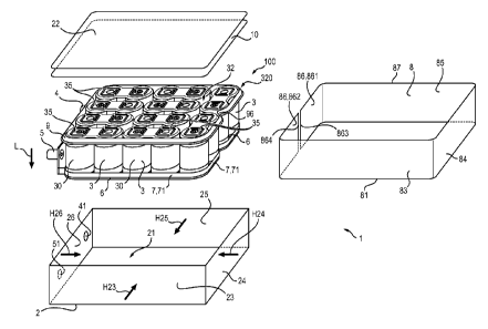
In the figures, a first wall 21 and at least one second
wall 23, 24, 25, 26 adjacent to this first wall 21 are provided
as outer walls. Once the outer case 2 has been assembled, in
the embodiment shown in Fig. 2, it has for example the general
form of a parallelepiped, with a first wall 21, which is a
CA 2863270 2017-07-18
13
first of the two walls of larger area of the parallelepiped,
and four second walls 23, 24, 25, 26 formed by the four other
walls of the parallelepiped, which are adjacent to this first
wall 21 and which are adjacent to each other, the wall 22 being
the other wall of largest area, opposite the wall 21 and
adjacent to the walls 23, 24, 25, 26 in the final assembly
state of the module 1 (the wall 22 is shown separate from the
other walls 21, 23, 24, 25 and 26 in Fig. 2 but is of course
fixed to the latter in the final assembly state). In the
following, the first wall 21 is called lower wall 21, the wall
22 is called upper wall, and the walls 23, 24, 25, 26 are
called lateral walls. But, of course, the module 1 can be
arranged with any walls 21, 22, 23, 24, 25, 26 arranged below
in the final assembly state.
The case 2 comprises electrical terminals 4, 5 accessible
from the outside. Electrical connection means are provided to
form between the terminals 4, 5 an electrical circuit with the
electrical energy-storage elements 3. The walls 21, 22, 23, 24,
25, 26 conduct electricity and for example are metal. These
walls 21, 22, 23, 24, 25, 26 are for example intended to be put
at the same electrical potential, for example at an electrical
earth. Insulating members are for example provided around the
terminals 4 and 5 for insulating these terminals 4, 5 from the
lateral wall 26 which they pass through, the wall 26 having two
holes 41, 51 for passage of the terminals 4, 5 and these
insulating members. The terminals 4, 5 are accessible from the
outside of the case 2 to allow them to be connected
electrically to an outer circuit.
The electrical energy-storage elements 3 are for example
ultracapacitors, each having an individual capacity of a value
greater than or equal to 1 Farad. The module 1 is capable of
being charged and discharged with electrical energy via the
terminals 4, 5. Of course, the module 1 can comprise other
electrical terminals accessible from the outside for its charge
and/or its discharge, and/or other communication access with
the outside and/or control via the outside and/or monitoring of
parameters from the outside.
CA 2863270 2017-07-18
14
These electrical energy-storage elements 3 are for example
connected in series by the connection means. Each electrical
energy-storage element 3 has for example two electrical
connection terminals. Each element 3 has for example a first
lower face 31 turned towards the first wall 21 and another face
32 turned away from this first face 31 and turned towards the
wall 22. A first of the connection terminals of the electrical
energy-storage element 3 is for example located on its first
face 31, whereas the second of the connection terminals of the
electrical energy-storage element 3 is for example located on
its second face 32. In the figures, each element 3 has a
general circular cylindrical form between its faces 31 and 32.
The elements 3 are arranged side by side in the case 2. The
axes of revolution of the elements 3 are for example
substantially parallel. In other variants not shown, the
electrical energy-storage elements can be in another form, for
example parallelepipedic, square, oval, hexagonal or other.
In the embodiment shown in the figures, the electrical
energy-storage elements 3 are arranged such that their axes of
revolution are perpendicular to the lower and upper walls 21,
22 of the case 2.
The connection means are for example formed by metallic
connection links 35 conducting electricity, connecting the
faces 31 in pairs and by other links 35 connecting the faces 32
of the elements 3 in pairs. The links are generally welded on
to the faces of the elements 3.
An embodiment shown in Figs. 1 to 10 is described
hereinbelow, wherein the first part 6 of the first positioning
spacer 7 is a first lining piece 60 formed by a first thermal
dissipation and electrical insulation piece 60 interposed
between the first wall 21 and the energy-storage elements 3.
In fact, the electrical energy-storage elements 3
preferably conduct heat according to their axis of revolution,
parallel to the longitudinal direction L shown in Fig. 2, such
that axial cooling of the electrical energy-storage elements 3
is more efficacious than cooling transversal to this direction
L. The thermal contacting of the electrical energy-storage
elements 3 with the first wall 21 improves cooling of the
CA 2863270 2017-07-18
15
electrical energy-storage elements 3 by an increase in the heat
exchange surface between the elements 3 and the outside of the
module 1.
The first thermal dissipation and electrical insulation
piece 60 is made of electrically insulating material and
conducts heat.
The first thermal dissipation and electrical insulation
piece 60 extends substantially parallel to the first wall 21 to
dissipate the heat released by the elements towards this first
wall 21.
In the final assembly state, when the assembled sub-set
100, comprising the electrical energy-storage elements 3 and
the first piece 60, is in the case 2, the first thermal
dissipation and electrical insulation piece 60 is in contact
with energy-storage elements 3 and is also in contact with the
first wall 21 to dissipate the heat released by the energy-
storage elements 3 towards this first wall 21.
According to an embodiment, the first thermal dissipation
and electrical insulation piece 60 comprises for example a
layer 60 extending between the elements 3 and the first wall 21
and extending at least opposite the elements 3.
According to an embodiment, the outer face 210 of the
first wall 21 is in contact with at least one supplementary
heat dissipation piece 211. According to an embodiment, the
supplementary heat dissipation piece 211 comprises for example
fins or more generally a device for increasing the contact
surface with the atmosphere relative to the surface of the face
21, to dissipate the heat towards the outside.
The first thermal dissipation and electrical insulation
piece 60 is for example made of deformable material. The first
thermal dissipation and electrical insulation piece 60 is for
example made of elastomer material, such as for example EPDM
(ethylene-propylene-diene monomer), and for example has
resistivity greater than 1012 ohm.cm and for example preferably
greater than 1014 ohm.cm.
The second part of the first positioning spacer 7
comprises a contact rim 71 against a part of the second wall
23, 24, 25. The rim 71 extends protruding transversally
CA 2863270 2017-07-18
16
relative to the first thermal dissipation and electrical
insulation piece 60. In this embodiment, the positioning spacer
7 is in a single piece with at least one part of the contour of
the first thermal dissipation and electrical insulation piece
60. The positioning spacer 7 is made of electrically insulating
material, especially, in the present case, the same material as
that of the dissipation piece. The rim 71 extends therefore
transversally relative to the first wall 21 and parallel
relative to the second wall 23, 24, 25. The rim 71 extends
transversally relative to the plane general wherein the first
thermal dissipation and electrical insulation piece 60 extends.
The rim 71 is for example perpendicular to the first thermal
dissipation and electrical insulation piece 60. The rim 71 is
for example perpendicular to the first wall 21. Of course, the
rim 71 could also extends in oblique relative to the first
thermal dissipation and electrical insulation piece 60 and/or
relative to the first wall 21. The rim 71 extends therefore
transversally relative to the first wall 21. In the embodiment
of Fig. 2, the rim 71 protrudes upwards above the first lower
wall 21. In the embodiment of Fig. 2, the rim 71 protrudes
upwards in the direction of the upper wall 22.
In other embodiments, such as for example that shown in
Fig. 11, the positioning spacer 7 can be a piece separate from
the first thermal dissipation piece 60. In an embodiment, the
positioning spacer 7 is placed on the first thermal dissipation
piece 60 such that the rim 71 is positioned to protrude
transversally from the dissipation piece 60. It can be placed
simply on the piece and kept in place by compression once the
module is in the final or fixed state on the dissipation piece,
for example by clipping or other on a part of the contour of
the first piece or on the whole contour of the first piece.
According to another embodiment of the invention, shown in
Fig. 11, the first part (6) of the spacer (7) is supported
against the first wall (21) with interposition of the first
lining piece (60).
In the embodiments shown in Figs. 1 to 10, the first
positioning spacer 7 is fixed to the whole of the contour of
the first piece 60. The positioning spacer 7 comprises for
CA 2863270 2017-07-18
17
example a contact rim 71 against each of the four second walls
23, 24, 25, 26, the rim being in a single piece.
Consequently, when the first piece 60 with the elements 3
above is in the case 2 in its final assembly state, as shown by
the walls 21, 23, 24, 25, 26 in Fig. 2, the positioning spacer
7 is applied by its rim 71 against the second walls 23, 24, 25
and/or 26, as is shown by way of example for the wall 23 in
Fig. 1, to ensure electrical insulation at the level of the
junction between this second wall 23, 24, 25, 26 and the
adjacent first wall 21. This spacer 7 guarantees that there
will be no insulation gap in the inner corners and the inner
ridges of the case (between the first wall 21 and the second
wall 23, 24, 25, 26).
In another embodiment, the positioning spacer 7 could be
fixed to a part of the contour of the first thermal dissipation
piece 60, for example opposite two or three second lateral
walls 23, 24, 25 adjacent to each other. It could also comprise
a plurality of rims in a single piece with the dissipation
piece but independant of each other.
Consequently, in an embodiment shown in Figs. 1, 2, 10 and
11, the outer case has the general form of a parallelepiped,
the first wall 21 is a first of the two faces of largest area
of the parallelepiped, adjacent to four other second faces of
the parallelepiped, including the second wall or second walls
23, 24, 25, the positioning spacer 7 comprising the contact rim
71 against a part of each of the second wall or second walls
23, 24, 25, 26.
In the embodiments shown in figures, the positioning
spacer 7 comprises on its rim 71 at least one projection 73 in
the direction of the wall 23 of the case. In the embodiments
shown, the at least one projection 73 extends parallel to the
first wall 21 in the direction of the wall 23 of the case. The
projection 73 of the rim 71 has a thickness greater than the
rest of the rim 71. This thickness is taken according to the
direction normal to the second wall. The projection is placed
on the face of the spacer turned towards the corresponding
second wall 23, 24, 25, 26. This projection 73 is located at a
distance from the free end 74 of the rim 71 such that the rim
CA 2863270 2017-07-18
18
71 has in the vicinity of the free end 74 a recess 72 serving
to house an edge 81 of a second lining piece 8 made of
electrically insulating material. This lining piece 8 is
located between the second wall 23, 24, 25, 26 and the elements
3. In the embodiment shown in Figs. 1 and 3, this recess 72 is
turned towards the corresponding second wall 23, 24, 25, 26,
that is towards the outside. A face 75 of the projection 73
essentially parallel to the wall 21 serves as positioning stop
of the lining piece 8. In the embodiment shown in Fig. 7, the
projection 73 extends continuously over the entire length of
the rim 71 along the faces 23, 24, 25. Alternatively, the rim
71 could comprise a plurality of projections 73 distributed
evenly over its entire length, the stop being formed by the
plurality of the upper walls of the projections 73 (located in
the same plane), distributed along the rim 71 and separated
from each other by empty spaces.
In an embodiment, the second lining piece 8 is made of
compressible material at least on its edge 81 housed in the
recess 72 to ensure it is kept in position of the edge 81 of
the second lining piece 8 in this recess 72. Compression of the
edge 81 of the second lining piece 8 in the recess 72 ensures
the lining piece 8 is kept in position by being wedged in to
the recess 72. Consequently, as is evident in Fig. 1, the edge
81 of the second lining piece 8 is between the second wall and
the free end 74 to be compressed in the recess 72. As a
variant, the lining piece 8 could be superposed on the rim 71
such that the projection 73 becomes embedded in the piece 8,
being held in place by compression.
The second lining piece 8 is made of synthetic material,
for example compressible foam.
The second lining piece 8 is for example peripheral to all
the elements 3. The lining piece 8 is for example opposite the
outside of the lateral surface 30 of those of the elements 3,
which are the most in the outside, that is those of the
elements 3 which are the closest and/or opposite walls 23, 24,
25, 26. The lining piece 8 is for example stuck by adhesive
material against the outside of the surface lateral 30 of those
of the elements 3, which are the more outside.
CA 2863270 2017-07-18
19
The second lining piece 8 extends along the second walls
23, 24, 25 and 26 and therefore comprises four faces,
respectively 83, 84, 85, 86 located opposite the walls 23, 24,
25, 26.
In the embodiment shown in Figs. 2 and 8, the second
lining piece 8 is for example a monobloc band, peripheral to
the elements 3, therefore with the faces 83, 84, 85, 86 joined
together. The face 86 is for example in two separate halves 861
and 862, being covered by the two ends 863 and 864 of the band
8. Consequently, the recess 72 containing the edge 81 of the
second lining piece 8 ensures double insulation because this
edge 81 covers the part 73 of the rim 71, which are both made
of electrically insulating material, as the same time as this
lining piece 8 is kept in position, to ensure reliably
continuity of the electrical insulation and to avoid gaps in
the electrical insulation.
The insulating lining element 8 is preserved from crushing
beyond its admissible limit in the recess 72 due to the
configuration of the rim and especially the dimensions of the
recess. It therefore retains all its electrical insulation
properties. The recess 72 therefore offers a visual marker to
the operator when he puts the lining element 8 in place.
In the embodiment shown in Fig. 5, the first piece 60 has
a flat surface 60 turned towards the elements 3.
In the embodiment shown in Fig. 6, the first piece 60
comprises on its surface 60 turned towards the elements 3,
hollows 601 for housing the first side 31 of the elements 3,
these housing hollows 601 being separated by pins 602. The
housing hollows 601 serve for example to border the side 31 of
two juxtaposed elements 3, and/or the connection links 35 or
some of the connection elements connecting the elements 3
together. This configuration enables separation of the elements
and insulation of the elements (each being of different
potential) relative to each other.
In the embodiments shown in Figs. 2, 3, 4 and 8, a second
positioning spacer 9 is also provided. This second positioning
spacer 9 comprises the first support part 92 and the second
part 91. This second spacer positioning 9 takes up space on the
CA 2863270 2017-07-18
20
interface of the wall 22 and lateral walls 23-26. This spacer 9
forms a spacing ring 9, ensuring, just like the spacer 7, the
link between the lining piece 8 and a third lining piece 10
stuck to the upper wall 22, for the sake of improvement of the
electrical insulation of the module and holding of lining
pieces.
The third lining piece 10 is arranged between the wall 22
and the second side 32 of the elements 3. This piece 10 is made
of electrically insulating material, for example compressible
synthetic material, and could be foam.
The ring 9 is mounted on the elements 3, by being
peripheral to these elements 3. The ring 9 is therefore located
in common against several of the elements 3, that is, against
the elements 3 which are located most to the outside. The ring
9 passes in common on the ouside of the second sides 32 of the
elements 3 located most to the outside, that is, those close to
the walls 23, 24, 25, 26. The ring 9 therefore surrounds
several elements 3.
As is shown in Figs. 3 and 4, the spacing ring 9 is
located in common against said zone of said elements 3, this
zone comprising the part of their proximal ridge 320 relative
to the walls 23, 24, 25, 26. For even better holding of the
elements 3 due to the spacing ring 9, the ring 9 comprises on
one of its sides a lip 96 forming a V moving away from the wall
of the case to follow the contour of the elements.
The spacing ring 9 comprises a first rim 91 and a second
rim 92 adjacent to the first rim 91. The two rims 91 and 92
serve to support against two adjacent sides of the external
elements 3 in said zone of the latter and against the walls
respectively 22 and 23, 24, 25, 26 of the case. These two
adjacent sides on the external elements 3 form a non-zero angle
together. The adjacent rims 91 and 92 form also a non-zero
angle between them, comparable to that present between the two
adjacent sides of the elements (or around 900). The rim 91 is a
support rim against the end of the surface lateral 30 of the
external elements 3, away from the first piece 60 and therefore
close to the second side 32 and against the walls 23-26. It
forms the second part of the second spacer 9. The rim 92 is a
CA 2863270 2017-07-18
21
support rim on the sides 32 of the elements 3, away from the
first piece 60, and against the wall 22. It forms the first
part of the second spacer 9.
The spacing ring 9 has for example a frame form having
rectilinear parts opposite the second walls.
The ring 9 comprises for example, as is shown in Fig. 3,
on its first rim 91 turned towards the second walls 23, 24, 25,
26, a projection 94 extending parallel to the wall 22 in the
direction of the wall 23 of the case. The projection 94 of the
rim 91 has a thickness greater than the rest of the rim 91.
This thickness is taken according to the direction normal to
the second wall. The projection is placed on the face of the
spacer turned towards the corresponding second wall 23, 24, 25,
26. This projection 94 is located at a distance from the free
end 97 of the rim 91 such that the rim 91 has in the vicinity
of the free end 97 a recess 93 serving to house another edge 87
of the second lining piece 8, which is that away from the first
edge 81. The recess 93 is turned towards the second wall 23,
24, 25 and/or 26. A face 98 of the projection 94 essentially
parallel to the wall 22 serves as positioning stop of the
lining piece 8. Therefore, when the edge 87 is in the recess
93, this edge 87 is wedged between the second wall 23, 24, 25
and/or 26 and the free end 97 of the rim 91, ensuring a good
fit in position of the piece 8 and at the same time ensuring
continuity of the electrical insulation in this zone by
avoiding electrical insulation gaps. The rim 92 could also
comprise a projection and/or a recess such as described
hereinabove to receive the lining piece 10.
It is evident that as a variant the lining piece 10 could
be in a single piece with the spacer 9 forming the interface
between the wall 22 and the lateral walls 23.
In the embodiments shown in Figs. 5, 6, 7 and 9, the
thermal dissipation piece 60 comprises one or more through-
holes 603 for passage or one or more metallic parts 212 fixed
to the first wall 21.
In Figs. 5 and 9, the hole 603 is for example extended
towards the inside, that is, towards the elements 3, by a
cylinder 604 fixed to the piece 60, specifically to the plaque
CA 2863270 2017-07-18
22
60, this cylinder or these cylinders 604 allowing passage of
the parts 212 and increasing the leak line between the part 212
and the elements 3 by the height of this cylinder 604 on the
piece 60, given that the cylinder 604 is made of electrically
insulating material, while the part 212 is made of material
conducting electricity. The parts 212 are for example metallic
reinforcements by which the lower wall 21 is fixed to the upper
wall 22, the case 2 and therefore this part 212 being for
example earthed, the case 2 being therefore at a potential
electrical different from at least one of the electrical
terminals of the elements 3.
In Figs. 6 and 7, the holes 603 are provided in the parts
in projection 602 of the piece 60, and are therefore at a
greater height than the hollow 61 receiving the elements 3.
To assemble the module 1, the sub-set 100 intended to be
enclosed by the case 2 is formed as follows.
The energy-storage elements 3 are first placed on the
first piece 60 supported by a rigid support tool.
Next, the ring 9 is placed on the outer part of the
external elements 3 to surround these elements 3.
The second lining piece 8 is placed around the external
elements 3, by sticking this piece 8 onto the outside of the
lateral surface 30 of the external elements 3 by means of
adhesive. The edge 81 of the piece 8 is placed in the recess 72
of the lower rim 71 of the spacer 7, whereas the upper edge 87
of the piece 8 is placed in the upper recess 93 of the upper
ring 9. This lining piece 8 has for example an adhesive side
turned towards the elements 3. This adhesive piece 8 for
example also keeps the cabling (connection means of the
elements 3) in place in the module 1. The two ends 863 and 864
of the piece 8 are for example placed overlapping on each other
by being for example placed in a corresponding part of the
piece 60, or butt-ended.
The sub-set 100 thus pre-assembled comprises the piece 60,
the spacer 7 fixed to the piece 60, the second lining piece 8
and the ring 9.
The second wall or second walls 23, 24, 25 and/or 26 are
then applied against the positioning spacer 7 in the respective
CA 2863270 2017-07-18
23
direction H23, 1-124, H25, H26 perpendicular to the rim 71 and
going towards the lining piece 8, that is, in the horizontal
directions H23, H24, H25, H26 in Fig. 2. These directions H23,
H24, H25, H26 of application of the respective walls 23, 24, 25
and/or 26 are therefore for example substantially parallel to
the piece 60 and to the first wall 21 and/or substantially
perpendicular to the lateral surfaces 30 of the elements 3. The
walls 23, 24, 25 and/or 26 are applied against the positioning
spacer 7 and against the spacing ring 9 to arrive in the
intermediate assembly position shown in Figs. 1 and 3, so a to
compress the edges 81 and 87 of the piece 8 in the recesses 72
and 93. In this intermediate assembly position, the first
spacer 7 is against the second walls 23, 24, 25 and/or 26. In
this assembly position, the ring 9 is against the second walls
23, 24, 25 and/or 26.
Then the lining piece 10 is put on the elements 3. The
wall 22 comprises for example this lining piece 10 fixed below.
The walls 22, 23, 24, 25 and 26 are then fixed to each other
for example by screws. Then the sub-assembly topped by the
walls 22, 23, 24, 25 and 26 fixed to each other is turned
round. The case 2 is then closed by fixing from above the wall
21 to the walls 23, 24, 25 and 26, the mechanical reinforcement
parts 212 being added through the holes 603, if necessary. The
module 1 is finally in the final assembly state.
The method according to the invention is not just what has
been described here: for example, as a variant, the spacer 7
could be arranged on the wall 21 before the elements 3 are
placed on the latter. Other modifications are also feasible.
Because of the invention, assembling the module is easy in
a reduced volume, resulting in a very short assembly cycle time
for the module of electrical energy-storage elements 3. The
reliability is also heightened relative to the electrical
insulation function.
CA 2863270 2017-07-18