Note: Descriptions are shown in the official language in which they were submitted.
CA 02863659 2016-05-10
COMBINED SCATTER AND TRANSMISSION MULTI-VIEW
IMAGING SYSTEM
FIELD OF THE INVENTION
The present specification relates generally to the field of X-ray imaging
system for
security scanning and more specifically to multi-view X-ray scanning systems
that
advantageously combine transmission and backscatter imaging.
BACKGROUND
With the proliferation of terrorism and contraband trade, there exists an
imminent need
for systems that can effectively and efficiently screen cars, buses, larger
vehicles and cargo to
detect suspicious threats and illegal substances.
In the past, many technologies have been assessed for use in security
inspection, and
often X-ray imaging has been identified as a reasonable technique for such
purposes. Several
known X-ray scanning systems have been deployed for screening cars, buses and
other vehicles.
Such systems include transmission and backscatter X-ray screening systems.
These prior art X-
ray systems provide scanning from a very limited number of orientations,
typically one and
potentially two. For example, a transmission X-ray system may be configured in
a side-shooter
or top-shooter configuration. Backscatter systems may be available in single
sided or,
occasionally, in a three sided configuration.
Accordingly, there is need in the prior art for a multi-view imaging system
which can
have an arbitrary number of views, and typically more than one. There is also
need in the art for
a modular multi-view system that results in high detection performance at very
low dose using a
combination of backscatter and transmission imaging methodologies.
SUMMARY OF THE INVENTION
The present specification discloses, in one embodiment, an X-ray inspection
system
comprising an X-ray source configured to emit an X-ray beam; and a detector
array comprising a
plurality of non-pixellated detectors, wherein at least a portion of said non-
pixellated detectors
are not oriented toward the X-ray source.
1
CA 02863659 2014-08-01
WO 2013/116549
PCT/US2013/024191
In another embodiment, the present specification discloses an X-ray inspection
system
comprising at least two X-ray sources, wherein each X-ray source is configured
to emit an X-
ray beam; and at least two detector arrays, wherein each detector array
comprises a plurality
of non-pixellated detectors, wherein at least a portion of said non-pixellated
detectors are
oriented toward both X-ray sources.
In yet another embodiment, the present specification discloses a multi-view X-
ray
inspection system having a three-view configuration comprising three X-ray
sources, wherein
each X-ray source rotates and is configured to emit a rotating X-ray pencil
beam; and at least
two detector arrays, wherein each detector array comprises a plurality of non-
pixellated
detectors, wherein at least a portion of said non-pixellated detectors are
oriented toward both
X-ray sources.
In an embodiment, the X-ray beam is a pencil beam and each X-ray source
rotates
over an angle of rotation, and the X-ray inspection system has an intrinsic
spatial resolution
and wherein said intrinsic spatial resolution is determined by a degree of
collimation of the
X-ray beam and not by a degree of pixellation of X-ray scan data. Further, in
an embodiment,
a single detector is exposed to only one X-ray beam from one of said X-ray
sources at a
specific point in time, and each detector defines a plane and wherein said
plane is offset from
each plane defined by each X-ray source. In an embodiment, each detector has a
rectangular
shape.
In another embodiment of the present invention, the X-ray inspection system
comprises at least one X-ray source configured to emit an X-ray beam; and a
detector array
comprising at least two rectangular profile backscatter detectors and a square
profile
transmission detector positioned between said at least two rectangular profile
backscatter
detectors.
In yet another embodiment, the present specification discloses an X-ray
inspection
system comprising at least one X-ray source configured to emit an X-ray beam;
and a
detector array comprising at least two rectangular profile backscatter
detectors, a square
profile transmission detector positioned between said at least two rectangular
profile
backscatter detectors, and a pair of fixed collimators positioned between the
square profile
transmission detector and one of said at least two rectangular profile
backscatter detectors.
In an embodiment, an X-ray inspection system comprising a control system
wherein,
when said X-ray inspection system is activated to detect gamma rays, said
control system
turns off an X-ray source and switches a detector data processing mode from
current
integrating mode to a pulse counting mode, is disclosed.
2
CA 02863659 2014-08-01
WO 2013/116549
PCT/US2013/024191
In another embodiment, the present invention discloses an X-ray inspection
system
having at least one X-ray source, wherein said X-ray source comprises an
extended anode X-
ray tube, a rotating collimator assembly, a bearing, a drive motor, and a
rotary encoder.
In yet another embodiment, the present invention discloses, an X-ray
inspection
system having at least one X-ray source, wherein said X-ray source comprises
an extended
anode X-ray tube, a rotating collimator assembly, a bearing, a drive motor, a
secondary
collimator set, and a rotary encoder.
In an embodiment, an X-ray inspection system comprising a control system
wherein
said control system receives speed data and wherein said control system
adjusts at least one
of a collimator rotation speed of an X-ray source, data acquisition rate, or X-
ray tube current
based upon said speed data, is disclosed.
In another embodiment, the present specification discloses an X-ray inspection
system
comprising a control system wherein said control system adjusts at least one
of a collimator
rotation speed of an X-ray source, data acquisition rate, or X-ray tube
current to ensure a
uniform dose per unit length of an object being scanned.
The present specification is also directed toward an X-ray inspection system
for
scanning an object, the inspection system comprising: at least two rotating X-
ray sources
configured to simultaneously emit rotating X-ray beams, each of said X-ray
beams defining a
transmission path; at least two detector arrays, wherein each of said at least
two detector
arrays is placed opposite one of the at least two X-ray sources to form a
scanning area; and at
least one controller for controlling each of the X-ray sources to scan the
object in a
coordinated manner, such that the X-ray beams of the at least two X-ray
sources do not cross
transmission paths.
In one embodiment, each of the emitted X-ray beams is a pencil beam and each X-
ray
source rotates over a predetermined angle of rotation.
In one embodiment, each detector is a non-pixellated detector.
In one embodiment, a first, a second and a third rotating X-ray sources are
configured
to simultaneously emit rotating X-ray beams, wherein the first X-ray source
scans the object
by starting at a substantially vertical position and moving in a clockwise
manner; wherein the
second X-ray source scans the object by starting at a substantially downward
vertical position
and moving in a clockwise manner; and wherein the third X-ray source scans the
object by
starting at a substantially horizontal position and moving in a clockwise
manner.
3
CA 02863659 2014-08-01
WO 2013/116549
PCT/US2013/024191
In one embodiment, the controller causes each X-ray source to begin scanning
the
object in a direction that does not overlap with an initial scanning direction
of any of the
remaining X-ray sources, thereby eliminating cross talk among the X-ray
sources.
In one embodiment, a plurality of scanned views of the object are collected
simultaneously with each detector being irradiated by no more than one X-ray
beam at any
one time.
In one embodiment, a volume of the detectors is independent of a number of
scanned
views of the object obtained.
In one embodiment, the X-ray inspection system has an intrinsic spatial
resolution
wherein said intrinsic spatial resolution is determined by a degree of
collimation of an X-ray
beam.
In one embodiment, the one or more detectors comprise an array of scintillator
detectors having one or more photomultiplier tubes emerging from an edge of
the detector
array to allow X-ray beams from adjacent X-ray sources to pass an unobstructed
face of the
detector array opposite to the photomultiplier tubes.
In one embodiment, the one or more detectors are formed from a bar of a
scintillation
material that has a high light output efficiency, a fast response time and is
mechanically
stable over large volumes with little response to changing environmental
conditions.
In one embodiment, the one or more detectors are gas ionization detectors
comprising
a Xenon or any other pressurized gas.
In one embodiment, the one or more detectors are formed from a semiconductor
material such as but not limited to CdZnTe, CdTe, HgI, Si and Ge.
In one embodiment, the X-ray inspection system is configured to detect gamma
rays
by turning off the X-ray sources switching the detectors from a current
integrating mode to a
pulse counting mode.
The present specification is also directed toward an X-ray inspection system
for
scanning an object, the inspection system comprising: at least two X-ray
sources configured
to simultaneously emit rotating X-ray beams for irradiating the object,
wherein each of said
X-ray beams defines a transmission path; a detector array comprising at least
one
transmission detector placed between at least two backscatter detectors,
wherein each of said
backscatter detectors detects backscattered X-rays emitted by a first X-ray
source placed on a
first side of the object and wherein the transmission detectors detects
transmitted X-rays
emitted by a second X-ray source placed on an opposing side of the object; and
at least one
controller for controlling each of the X-ray sources to concurrently scan the
object in a
4
CA 02863659 2014-08-01
WO 2013/116549
PCT/US2013/024191
coordinated, non-overlapping, manner such that the transmission paths of each
of said X-ray
beams does not cross.
In one embodiment, the detector array comprises at least two rectangular
profile
backscatter detectors and a square profile transmission detector positioned
between said at
least two rectangular profile backscatter detectors.
In another embodiment, the detector array comprises a transmission detector
positioned between two backscatter detectors wherein the detectors are placed
within a single
plane facing the object begin scanned and the transmission detector has a
smaller exposed
surface area than each of the backscatter detectors.
In one embodiment, the X-ray inspection system further comprises a pair of
fixed
collimators positioned between the transmission detector and one of said at
least two
backscatter detectors.
In one embodiment, each of the X-ray sources comprises an extended anode X-ray
tube, a rotating collimator assembly, a bearing, a drive motor, and a rotary
encoder.
In another embodiment, each of the X-ray sources comprises: an extended anode
X-
ray tube coupled with a cooling circuit, the anode being at ground potential;
a rotating
collimator assembly comprising at least one collimating ring with slots cut at
predefined
angles around a circumference of the collimator, a length of each slot being
greater than a
width and an axis of rotation of the slot, and the width of the slots defining
an intrinsic spatial
resolution of the X-ray inspection system in a direction of the scanning; a
bearing for
supporting a weight of the collimator assembly and transferring a drive shaft
from the
collimator assembly to a drive motor; a rotary encoder for determining an
absolute angle of
rotation of the X-ray beams; and a secondary collimator set for improving
spatial resolution
in a perpendicular scanning direction.
In one embodiment, the controller receives speed data comprising a speed of
the
object and, based upon said speed data, adjusts at least one of a collimator
rotation speed of
an X-ray source, a data acquisition rate, or an X-ray tube current based upon
said speed data.
The aforementioned and other embodiments of the present shall be described in
greater depth in the drawings and detailed description provided below.
BRIEF DESCRIPTION OF THE DRAWINGS
These and other features and advantages of the present invention will be
appreciated,
as they become better understood by reference to the following detailed
description when
considered in connection with the accompanying drawings:
5
CA 02863659 2014-08-01
WO 2013/116549
PCT/US2013/024191
FIG. 1 shows a single-view top-shooter transmission imaging system in
accordance
with one embodiment of the present invention;
FIG. 2 is a first side-shooter configuration of one embodiment of the present
invention;
FIG. 3 is a second side-shooter configuration of one embodiment of the present
invention;
FIG. 4 is a multi-view X-ray imaging system embodiment of the present
invention;
FIG. 5 shows X-ray detector offset geometry from a plane of X-ray sources for
use in
the multi-view X-ray imaging system of the present invention;
1 0 FIG. 6 shows an embodiment of a suitable X-ray detector for use in the
multi-view
system of the present invention;
FIG. 7a is a side view of a detector array for use in the multi-view system of
the
present invention;
FIG. 7b is an end view of the detector array for use in the multi-view system
of the
1 5 present invention;
FIG. 8 shows an embodiment of a backscatter-transmission detector
configuration for
use with multi-view system of the present invention;
FIG. 9 shows an alternate embodiment of the backscatter-transmission detector
configuration for use with multi-view system of the present invention;
20 FIG. 10 shows an embodiment of a suitable scanning X-ray source for use
with multi-
view system of the present invention;
FIG. 1 1 a shows a secondary collimator set to improve spatial resolution in
the
perpendicular direction;
FIG. 1 lb shows the secondary collimator set of FIG. 1 1 a positioned around
an outer
25 edge of a rotating collimator;
FIG. 12 shows an embodiment of read-out electronic circuit for use with
detectors of
the multi-view system of the present invention;
FIG. 13 shows a matrixed configuration where a set of 'n' multi-view imaging
systems are monitored by a group of 'm' image inspectors;
30 FIG. 14 shows a deployment of a multi-view imaging system to scan cargo,
in
accordance with an embodiment of the present invention;
FIG. 15 shows a deployment of a multi-view imaging system to scan occupied
vehicles in accordance with an embodiment of the present invention;
FIG. 16a shows a mobile inspection system in its operating state ready for
scanning;
6
CA 02863659 2016-05-10
FIG. 16b shows the step of folding up of vertical boom about a hinge point at
the end of
horizontal boom;
FIG. 16c shows the step of folding up the horizontal boom and, concurrently,
the vertical
boom around a hinge point at the top of a vertical support;
FIG. 16d shows the step of laying down the vertical boom toward the back of
the mobile
inspection vehicle;
FIG. 16e shows the step of folding up the bottom imaging section by at least
90 degrees
from its operating position;
FIG. 16f shows the step of folding an outer horizontal base section by 180
degrees to
cause it to lie parallel to inner base section; and
FIG. 16g shows the step of completely folding the base section by 90 degrees
to complete
the system stow.
DETAILED DESCRIPTION OF THE INVENTION
The present specification is directed towards an X-ray scanning system that
advantageously combines image information from both backscatter and
transmission
technologies. More specifically, the present invention employs four discrete
backscatter
systems, however re-uses the pencil beam from one backscatter system to
illuminate large area
detectors from a second backscatter system so that simultaneous multi-sided
backscatter and
transmission imaging using the same set of four X-ray beams can be achieved.
This approach is
cost effective, in that it saves the cost of a segmented detector array yet
still provides a
comprehensive inspection.
The present specification is directed towards multiple embodiments. The
following
disclosure is provided in order to enable a person having ordinary skill in
the art to practice the
invention. Language used in this specification should not be interpreted as a
general disavowal
of any one specific embodiment or used to limit the claims beyond the meaning
of the terms used
therein. The general principles defined herein may be applied to other
embodiments and
applications without departing from the scope of the present specification.
Also, the terminology
and phraseology used is for the purpose of describing exemplary embodiments
and should not be
considered limiting. Thus, the present invention is to be accorded the widest
scope encompassing
numerous alternatives, modifications and equivalents consistent with the
principles and features
disclosed. For purpose of clarity, details relating to technical material that
is known in the
technical fields related to the
7
CA 02863659 2014-08-01
WO 2013/116549
PCT/US2013/024191
invention have not been described in detail so as not to unnecessarily obscure
the present
invention.
FIG. 1 shows a single-view top-shooter transmission imaging system 100 in
accordance with an embodiment of the present invention. System 100 comprises
an X-ray
source 105 with a rotating pencil beam collimator. When the X-ray beam is on,
the collimator
rotates continuously to form a moving X-ray beam 110 that sweeps over a fan-
shaped area
115. A series of X-ray detectors 120 are placed in a transmission inspection
geometry,
namely opposite the X-ray beam 110 and with the inspected object between the
detectors 120
and X-ray beam 110, to record the intensity of the X-ray beam 110 once it has
passed through
object 125, such as a vehicle. In one embodiment, detectors 120 are on the
order of 1000 mm
long and stacked end-to-end to form a linear sensor having a length equal to a
plurality of
meters. An advantage of such detectors is that they can be fabricated quite
inexpensively,
since they do not have spatial resolution.
An X-ray scan image, of the object 125, is formed by recording intensity of
signal at
output of each detector 120 at all times, as well as the angle of rotation of
the X-ray pencil
beam 110. In radial coordinates, object X-ray transmission is determined by
plotting the
recorded X-ray intensity from X-ray detectors 120 which is being pointed to by
the X-ray
beam 110 against its angle of rotation at any given instant. As known to
persons of ordinary
skill in the art a predetermined coordinate transform maps this data back onto
a Cartesian grid
or any other chosen co-ordinate grid.
In contrast to typical prior art X-ray imaging systems, the intrinsic spatial
resolution
of the system 100 is determined not by pixellation of the X-ray scan data but
by collimation
of the X-ray beam 110 at the source 105. Since the X-ray beam 110 is produced
from a small
focal spot with finite area, the X-ray pencil beam 110 is diverging and
therefore the spatial
resolution of the system 100 varies with distance of the detectors 120 from
the source 105.
Therefore, spatial resolution of the system 100 is least in the lower corners
directly opposite
to the X-ray source 105. However, this varying spatial resolution is corrected
by
deconvolution of the spatial impulse response of the system 100 as a function
of rotation
angle to thereby produce an image with constant perceptible spatial
resolution.
FIG. 2 is a side-shooter configuration, of the system 100 of FIG. 1, that uses
a similar
identical X-ray source 205 with a rotating pencil beam 210 and a series of
identical X-ray
detectors 220 but in alternative locations. As shown in FIG. 3, a mirrored
side-shooter
configuration is achieved using the same X-ray source 305 and detectors 320
but in a mirror
image configuration to that shown in FIG. 2.
8
CA 02863659 2014-08-01
WO 2013/116549
PCT/US2013/024191
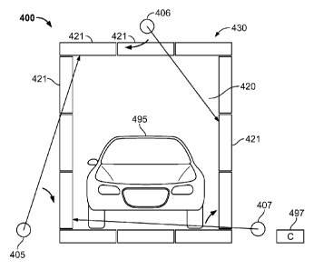
FIG. 4 is a multi-view X-ray imaging system 400 that integrates the
configurations of
FIG.s 1 through 3 in accordance with an embodiment of the present invention.
In one
embodiment, system 400 has a three-view configuration enabled by three
simultaneously
active rotating X-ray beams 405, 406 and 407 with plurality of detectors
placed
correspondingly, in one embodiment, in transmission configuration to form a
scanning tunnel
420. System 400 provides a high degree of inspection capability, in accordance
with an object
of the present invention, while at the same time achieving this at
substantially low X-ray dose
since the volume of space irradiated at any moment in time is low compared to
conventional
prior art line scan systems that typically have large numbers of pixellated X-
ray detectors and
fan-beam X-ray irradiation.
As shown in FIG. 4, there is almost no cross talk between the three X-ray
views
which are collected simultaneously because the X-ray sources 405, 406, 407,
are controlled
by at least one controller 497, which may be local to or remote from the X-ray
sources 405,
406, 407, that transmits control signals to each X-ray source 405, 406, 407 in
a manner that
causes them to scan the target object 495 in a coordinated, and non-
overlapping, manner. In
one embodiment, X-ray source 405 scans object 495 by starting at a
substantially vertical
position (between 12 o'clock and 1 o'clock) and moving in a clockwise manner.
Concurrently, X-ray source 406 scans object 495 by starting at a substantially
downward
vertical position (around 4 o'clock) and moving in a clockwise manner.
Concurrently, X-ray
source 407 scans object 495 by starting at a substantially horizontal position
(around 9
o'clock) and moving in a clockwise manner. It should be appreciated that each
of the
aforementioned X-ray sources could begin at a different position, provided
that a) each starts
a scan in a direction that does not overlap with the initial scanning
direction of the other X-
ray sources and b) each scans in a direction and at a speed that does not
substantially overlap
with the scan of the other X-ray sources.
According to an aspect of the present invention, there is almost no limit to
the number
of views which may be collected simultaneously in the system 400 with each
detector
segment 421 being irradiated by no more than one primary X-ray beam at any one
time. In
one embodiment, the detector configuration 430, shown in FIG. 4, comprises 12
detector
segments 421 each of approximately lm in length to form an inspection tunnel
of
approximately 3m (Width) x 3m (Height). In one embodiment, the detector
configuration 430
is capable of supporting six independent X-ray views to allow transition of
the sweeping X-
ray views between adjacent detectors. An alternate embodiment comprising 0.5m
long
detector segments 421 is capable of supporting up to 12 independent X-ray
image views.
9
CA 02863659 2014-08-01
WO 2013/116549
PCT/US2013/024191
Persons of ordinary skill in the art should appreciate that, in system 400,
the volume
of detector material is independent of the number of views to be collected and
the density of
readout electronics is quite low compared to conventional prior art pixellated
X-ray detector
arrays. Additionally, a plurality of X-ray sources can be driven from a
suitably rated high
voltage generator thereby enabling additional X-ray sources to be added
relatively simply and
conveniently. These features enable the high density multi-view system 400 of
the present
invention to be advantageously used in security screening applications.
As shown in FIG. 5, a multi-view system, such as that shown in FIG. 4, has X-
ray
detectors 520 offset from the plane of the X-ray sources 505. The offset
prevents X-ray
beams 510 from being absorbed relatively strongly in the detector nearest to
it, before the
beam can enter the object under inspection.
According to another aspect, X-ray detectors are not required to have a
spatial
resolving function thereby allowing the primary beam to wander over the face
of the detector,
and to a side face of the detector, with minimal impact on overall performance
of the imaging
system. This considerably simplifies the detector configuration in comparison
to a
conventional prior art pixellated X-ray system, since, in a pixellated system,
each detector
needs to be oriented to point back towards a corresponding source to maintain
spatial
resolution. Thus, in prior art pixellated X-ray systems, a single detector
cannot point to more
than one source position and, therefore, a dedicated pixellated array is
needed for each source
point.
FIG. 6 shows an embodiment of a suitable X-ray detector 600 for use in a multi-
view
system (such as the three-view system 400 of FIG. 4) of the present invention.
As shown,
detector 600 is formed from a bar 605 of X-ray detection material, that in one
embodiment is
fabricated from scintillation material. In a scintillation process, X-ray
energy is converted to
optical photons and these photons are collected using a suitable optical
detector, such as a
photomultiplier tube or photodiode 610. Suitable scintillation detection
materials comprise
plastic scintillators, CsI, BGO, NaI, or any other scintillation material
known to persons of
ordinary skill in the art that has high light output efficiency, fast time
response and is
mechanically stable over large volumes with little response to changing
environmental
conditions. Alternatively, detector materials can also comprise gas ionisation
and gas
proportional detectors, ideally with pressurised gas to enhance detection
efficiency and high
electric field strengths for improving signal collection times. Noble gas
based detectors such
as pressurised Xenon detectors are quite suitable for use with the multi-view
system of
present invention. Semiconductor detector materials could also be adopted,
such as CdZnTe,
CA 02863659 2014-08-01
WO 2013/116549
PCT/US2013/024191
CdTe, HgI, Si and Ge, although the capacitance, response time, costs and
temperature
response of these materials make them a less preferred choice.
An array of scintillator detectors 720 is shown in FIG.s 7a and 7b with
photomultiplier tubes 725 emerging from the same long edge of scintillating
material to allow
X-ray beams from adjacent X-ray sources to pass the unobstructed face of the
detector
opposite to the photomultiplier tubes 725. Two X-ray sources 705, 706 are
visible in the side
view of the detector array 720 of FIG. 7a. Three X-ray sources 705, 706, 707
are visible in
the end view of FIG. 7b.
From X-rays which are transmitted straight through an object and to a set of
transmission detectors on the opposite side of the object, a fraction of the X-
rays scatter from
the object into other directions. It is known to those of ordinary skill in
the art that the
probability of detecting a scattered X-ray varies with the inverse square of
distance of the
detector from the scattering site. This means that a detector placed proximate
to an X-ray
beam, as it enters the object, will receive a much larger backscatter signal
than a detector
placed at significant distance from X-ray source.
FIG. 8 shows an embodiment of a detector configuration for use with multi-view
system of the present invention to utilize X-rays backscattered from an object
under
inspection, in addition to transmitted X-rays. In this embodiment, an X-ray
source 805
illuminates object 825 with a scanning pencil beam 810 of X-rays. A fraction
of the X-rays
815 backscatter, which are then sensed by a pair of rectangular detectors 821,
822.
Transmission X-ray beam 830 from a second X-ray source (not shown) at the
other side of
the object 825, is captured at a smaller square section detector 835.
It should be noted herein that the detectors can be of any shape and are not
limited to
a rectangular shape. In this particular embodiment, a rectangular shape is
selected because it
produces a uniform response and has a relatively manufacturing cost. In
addition, a
rectangular shape is easier to stack end-to-end compared with a circular or
other curved
detector. Similarly, using a smaller square cross-section will most likely
yield the most
uniform response, for example, when compared to a cylindrical detector with a
circular cross
section, and is relatively lower in cost to manufacture.
The square profile transmission detector 835 is placed between the two
rectangular
profile backscatter detectors 821, 822. A pair of fixed collimators 840
substantially reduces
the effect of scattered radiation on the transmission detector 835, resulting
from a nearby X-
ray source, which measures relatively weak transmission signals from the
opposing X-ray
source (not shown). All detectors 821, 822 and 835 are shielded using suitable
materials, such
11
CA 02863659 2014-08-01
WO 2013/116549
PCT/US2013/024191
as steel and lead, around all faces except their active faces to avoid
background signal due to
natural gamma-radiation and unwanted X-ray scattering. Therefore, a
transmission detector
is sandwiched between two backscatter detectors, within a single plane facing
the object
begin scanned, and the transmission detector has a smaller exposed surface
area than each of
the backscatter detectors.
Figure 9 shows an alternate embodiment of combined X-ray backscatter-
transmission
detectors. Here, a large imaging panel 900, which in one embodiment ranges
from 1.5 m to
3.0 m in total length, comprises six individual X-ray detectors in addition to
a scanning X-ray
source 905. Four of the detectors 910, 911, 912 and 913 are used for recording
X-ray
backscatter from the local X-ray source 905, while two detectors 914, 915
having smaller
exposed surface areas than each of the backscatter detectors 910, 911, 912,
913 are used to
record transmission X-ray signals from an opposing X-ray generator.
Persons of ordinary skill in the art should note that with the detector
configurations of
Figures 8 and 9, a multi-view backscatter system of the present invention is
achieved that has
one backscatter view corresponding to each transmission view.
According to a further aspect, transmission imaging detectors can also be used
for
recording backscatter signals when not being directly irradiated by a
transmission imaging
beam. However, use of additional detection sensors, as shown in Figures 8 and
9 substantially
improve sensitivity of the backscatter detectors albeit at substantially
higher cost. Therefore,
a low cost system with modest backscatter performance can be assembled using
just a single
detector array in offset geometry as shown in Figures 5 and 6.
In one embodiment, the additional backscatter imaging panels are formed from a
low
cost high volume detector material such as scintillation materials comprising
plastic
scintillators, scintillation screens such as GdO2S with optical light guides,
and solid
scintillators such as CsI and NaI although any scintillator known to those of
ordinary skill in
the art may be used, providing it has a fast response time (< 10 us primary
decay time), good
uniformity, and stability against change in ambient conditions. Semiconductor
and gas filled
detectors may also be used, although these are less preferred with the
exception of pressured
Xenon gas detectors.
According to yet another aspect of the present invention, the large area array
of
detector panels of Figures 8 and 9 are also used as passive detectors of gamma
radiation such
as that emitted from special nuclear materials and other radioactive sources
of interest such as
Co-60, Cs-137 and Am-241. To enable system sensitivity to passive gamma rays,
the X-ray
sources are turned off and the detector electronics switched from a current
integrating mode
12
CA 02863659 2014-08-01
WO 2013/116549
PCT/US2013/024191
to a pulse counting mode. The object, such as a vehicle, under inspection is
first scanned
with the X-ray system of the present invention. It should be noted herein that
the method of
the present invention can be used in a single-view configuration or a multi-
view
configuration. If a suspicious item is detected, the vehicle is re-scanned,
this time, in passive
detection mode. This provides dual operating function capability for the
imaging system of
the present invention. Further, due to spatial positioning of the detector
panels, it is possible
to approximately localize radioactive source in space (recognizing the inverse
square
reduction of count rate at detectors due to the distance of the detector from
the source). This
localization is applied to the multi-view X-ray images in the form of a
graphic overlay to
show the position of a passive gamma source.
As shown in Figure 10, an embodiment of a suitable scanning X-ray source 1000,
for
use with multi-view system of the present invention, comprises an extended
anode X-ray tube
1005, a rotating collimator assembly 1010, a bearing 1015, a drive motor 1020,
and a rotary
encoder 1025.
In one embodiment, extended anode X-ray tube 1005 has the anode at ground
potential. The anode is provided with a cooling circuit to minimize the
thermal heating of the
target during extended operating periods. In one embodiment, a rotating
collimator assembly
1010 is advantageously formed from suitable engineering materials such as
steel and
tungsten. The collimator comprises at least one collimating ring with slots
cut at appropriate
angles around circumference of the collimator. The length of each slot is
greater than its
width and is longer than its axis of rotation and narrow in the direction of
rotation. Width of
the slots defines intrinsic spatial resolution of the transmission imaging
system in the
direction of the scanning.
Bearing 1015 supports the weight of the collimator assembly 1010 and transfers
a
drive shaft from the collimator assembly to a drive motor 1020. The drive
motor 1020 is
capable of being speed controlled using an electronic servo drive to maintain
exact speed of
rotation. A rotary encoder 1025 provides absolute angle of rotation since this
is required to
determine the position of each sampled detector point in the final generated
image.
The rotating X-ray beam produced by the source 1000 of Figure 10 has good
resolution in one dimension only. To improve spatial resolution in the
perpendicular
direction, a secondary collimator set is provided as shown in Figures 11 a and
1 lb. Referring
now to Figures 11 a and 1 lb simultaneously, hoop-like collimators 1100 are
placed around
outer edge of the rotating collimator 1110 to provide collimation into beam
width direction.
Since in one embodiment transmission detectors are likely to be of a square
section (such as
13
CA 02863659 2014-08-01
WO 2013/116549
PCT/US2013/024191
detectors 835 of Figure 8) and. when combined with offset system geometry of
the present
invention (as discussed with reference to Figure 5), use of a secondary beam
width collimator
1110 allows a specific shape of beam to be produced which precisely follows
the center line
of the imaging detectors.
In an embodiment of the present invention, additional collimation is placed at
transmission detectors to constrain the width of X-ray beam before it enters
the detection
material itself This allows an image of arbitrary spatial resolution to be
collected even if an
actual X-ray beam passing through object is of lower intrinsic spatial
resolution. The width of
the X-ray beam passing through the object is kept as small as possible, but
consistent with the
final collimator slot width, in order to minimise dose to the object under
inspection.
Each detector in the multi-view system is provided with readout electronics
which
biases the photodetector, buffers and amplifies output signal from the
photodetector and
digitizes the resulting signal. Figure 12 shows an embodiment of
photomultiplier tube circuit
1205 with buffer amplifier and high speed analogue-to-digital (ADC) converter
1210. Data
from the ADC 1210 is transferred into a system controller circuit 1215 along
with digital data
from all of the other photodetectors (DETi, DET2, ..., DET.). The system
controller 1215
also takes in encoder data 1220 from each of X-ray sources and provides motor
drive signals
1225 to each X-ray source. Thus, the system controller 1215 coordinates data
acquisition
between each component of the detector system and generates an image data
stream 1230
which provides data individually for each transmission and backscatter X-ray
view.
A set of suitable sensors 1235 are used to measure speed of the vehicle or
object
under inspection as it passes through the inspection region. Suitable sensors
comprise
microwave radar cameras, scanning infra-red lasers or simply inductive sensors
placed at
known distance apart which can provide a measurement of speed (=
distance/time) by
comparing the times at which each sensor goes from false to true and vice
versa as the
vehicle scans past. This speed information, in one embodiment, is passed to
the system
controller 1215 which then adjusts collimator rotation speed, data acquisition
rate and X-ray
tube current to ensure a uniform dose per unit length of the object being
scanned. By using a
high speed ADC 1210, multiple samples are acquired at each transmission and
backscatter
source point so that an average value, or otherwise filtered value, is stored
to improve signal-
to-noise ratio of the imaging system.
The linear scanning velocity of X-ray beams across the face of a transmission
imaging
detector varies as a function of the distance from the source (i.e., more
distant points suffer a
faster linear scan rate). Therefore, in one embodiment, use of a high speed
oversampling
14
CA 02863659 2014-08-01
WO 2013/116549
PCT/US2013/024191
analogue-to-digital converter 1210 simplifies the adjustment of sample time to
match the
linear scanning velocity using, for example, encoder data 1220 to trigger the
start of each
sampling period, where the relevant encoder values are stored in a digital
lookup table prior
to the start of scanning. Sampling of data at a high speed allows for an
improved de-
convolution of the spatial resolution in the scanning direction by
oversampling the measured
data and generating a lower sample rate output image data compared to that
which would be
achieved by trying to de-convolve only a low sample rate image.
According to an embodiment, the system controller 1215 is advantageously
designed
using a combination of digital electronics, such as a field programmable gate
array, and a
microcontroller. The digital circuits provide precise timing that is required
to build up a
scanned image from multiple detectors and multiple encoders in an automated
fashion, using
only data from the encoders 1220 to coordinate activity. One or more
microcontrollers
provide system configuration capability, in-system programmability for field
upgrade of
firmware, and support for final data transmission process.
An embodiment utilizes a matrixed configuration where a set of 'n' multi-view
imaging systems are monitored by a group of 'm' image inspectors. In this
configuration, as
shown in Figure 13, each imaging system SYS 1, 5)(52, ... SYSn is connected to
a network
1315 which provides a database 1305 for storage and recall of all image data.
A job scheduler
1310 keeps track of which systems are online and of which operators INSPECTi,
INSPECT2,
... INSPECTm are available for inspection. Images from the database 1305 are
transferred
automatically to the next available inspector for review. Inspection results
are passed back to
the relevant imaging system which advantageously comprises traffic control
measures to
direct manual search of suspect vehicles or objects under inspection. System
supervisor 1320
is, in one embodiment, a manager who can monitor the state of the imaging
systems, monitor
the efficiency of the operators and can double-check inspection results from
inspectors.
Figure 14 shows deployment of multi-view imaging system to scan cargo, in
accordance with an embodiment of the present invention, comprising a gantry
1400 with
main imaging system (such as the three-view system 400 of Figure 4) at its
center along with
drive-up and drive-down ramps 1410, 1411 respectively provided to allow
vehicles to pass
through the centre of the inspection tunnel 1405. In an alternate embodiment,
the gantry 1400
is provided with a conveyor to transport cargo through the inspection tunnel
1405. In one
embodiment, suitable tunnel sizes are up to 800mm x 500mm for small baggage,
up to
1800mm x 1800mm for packets and small cargo, up to 3000mm x 3000mm for small
vehicles
and large cargo and up to 5500mm x 4000mm for large vehicles and containerized
cargo.
CA 02863659 2014-08-01
WO 2013/116549
PCT/US2013/024191
Figure 15 shows deployment of multi-view imaging system to scan occupied
vehicles
in accordance with an embodiment of the present invention, where vehicles in a
multi-lane
road 1500 approach a plurality of scanners 1505, one scanner per lane.
Vehicles 1525 are
scanned as they pass through respective scanners and approach a plurality of
corresponding
traffic control systems 1510 such as barrier or other suitable traffic control
measures,
including traffic lights. Decision results from image inspectors are passed
automatically to
these traffic control systems 1510 which then hold or divert traffic as
necessary. In an
example illustration, a holding area 1515 is shown with a vehicle 1520 parked
therein as a
result of an inspector/operator marking scanned image of the vehicle 1520 as
suspicious.
In accordance with another aspect, the multi-view imaging system of the
present
invention is deployed in the form of a mobile inspection vehicle for rapid
relocation to an
inspection site. Figure 16a shows mobile inspection system 1600 in its
operating state ready
for scanning. Vehicle 1605 carries an embodiment of a multi-view detection
system, where a
scanning tunnel 1610 is surrounded by a set of booms 1615, 1621, 1622.
An exemplary boom stow sequence is graphically illustrated using FIG.s 16b
through
16g as follows:
Figure 16b shows step 1650 comprising the folding up of vertical boom 1620
about a
hinge point 1601 at the end of horizontal boom 1621. This can be achieved, for
example, by
using a hydraulic cylinder actuation although other mechanisms known to those
of ordinary
skill in the art may be considered such as pull wires and electronic drivers.
Step 1655, shown in Figure 16c, comprises the simultaneous folding up of
horizontal
boom 1621 and vertical boom 1620 about a hinge point 1602 which is positioned
at the top of
vertical support boom 1622.
Step 1660, shown in Figure 16d, comprises lowering vertical support boom 1622
toward the back of the vehicle 1605. Vertical support boom 1622 may be folded
down to a
steep angle to allow room for an operator inspection cabin to be co-located on
the back of the
vehicle. In another embodiment, vertical support boom 1622 may be folded down
to be
substantially parallel to the back platform of the vehicle to allow a compact
system
configuration which is advantageously developed to allow rapid re-location of
systems using
conventional air transportation.
Step 1665, shown in Figure 16e, comprises folding up the base section 1625 of
the
imaging system by at least 90 degrees from its operating position. Thereafter,
in step 1670, as
shown in FIG. 16f, comprises folding the outer horizontal base section 1625a
of the main
base section 1625 by 180 degrees so that it lies parallel to the inner base
section 1625b.
16
CA 02863659 2016-05-10
Finally, in step 1675, shown in Figure 16g a complete folding of the base
section occurs
by a 90 degree rotation to complete system stow. The aforementioned steps,
1650 through 1675,
for boom deployment to obtain operating state of Figure 16a comprise boom stow
steps in
reverse sequence.
In alternate embodiments, the mobile inspection system 1600 is deployed with
only the
vertical and horizontal booms and not the lower imaging section. This gives
dual view imaging
capability in side-shooter configuration but no top-shooter view. In this
mode, the system is
capable of full drive-by scanning mode with an imaging configuration of at
least one
transmission view, with or without backscatter capability.
The above examples are merely illustrative of the many applications of the
system of
present invention. Although only a few embodiments of the present invention
have been
described herein, it should be understood that the present invention might be
embodied in many
other specific forms without departing from the scope of the present
specification. Therefore, the
present examples and embodiments are to be considered as illustrative and not
restrictive. The
scope of protection being sought is defined by the following claims rather
than the described
embodiments in the foregoing description. The scope of the claims should not
be limited by the
described embodiments set forth in the examples but should be given the
broadest interpretation
consistent with the description as a whole.
17