Note: Descriptions are shown in the official language in which they were submitted.
- 1 -
Method and Device for Determining Distance and Radial Velocity
of an Object by means of Radar Signals
The invention relates to a method for determining the distance
and radial velocity of an object in relation to a measurement
location, with which radar signals are transmitted from the
measurement location and received again after reflection at the
object, wherein the transmitted radar signals are subdivided
within a measurement cycle into numerous segments, in which
they are changed in their frequency from an initial value to a
final value and the received reflected signals are each
subjected over a segment to a first evaluation for detecting
frequency peaks and additionally a subsequent second evaluation
of the signals for the frequency peaks of all segments of the
measurement cycle is carried out to determine a Doppler
frequency component as a measure of the radial velocity.
The invention further relates to a device for determining the
distance and radial velocity of an object in
relation to a
measurement location, with a radar transmitter, a receiver
disposed at the measurement location for radar signals of the
radar transmitter reflected from the object, wherein the radar
signals are subdivided within a measurement cycle into numerous
segments, in which they are changed in their frequency from an
initial value to a final value, with a first evaluation device
connected to the receiver for detecting frequency peaks within
each of the segments of the received signals, and with a second
evaluation device connected to the first evaluation device for
the evaluation of a phase difference of the determined
frequency peaks for determining a Doppler frequency component
as a measure of the radial velocity.
It is known to determine both the distance and also the
radial velocity of an object relative to a measurement
CA 2867062 2018-08-10
CA 02867062 2014-09-11
WO 2013/156012 - 2 -
PCT/DE2013/000154
location by means of suitably modulated radar signals
with a measurement.
A suitable known type of modulation of the radar
signals is described in EP 1 325 350 El. With this two
nested ramps A and B are modulated during a measurement
cycle of e.g. 65 ms length 512 sample
values
of the reflected signal are recorded per ramp and
evaluated separately for each ramp. The evaluation is
carried out by means of FFT (Fast Fourier
Transformation) with a total of 2 x 512 sampling
points. Accordingly, the sampling period is 65 ms/2 x
512 = 63.48 As. The sampling frequency is thus 15.75
kHz, wherein the effective sampling frequency per ramp
is half this value, i.e. 7.88 kHz. The Doppler
frequency range of 7.88 kHz corresponds to a unique
velocity measurement range of 49 m/s for a carrier
frequency of 24.125 GHz. The unique velocity
measurement range corresponds to 176.4 km/h, and is
thus suitable for use in road traffic in general,
because the measurement location, i.e. the radar
transmitter and radar receiver, is normally disposed in
the vehicle and radial velocities between traveling
vehicles of > 175 km/h - at least in urban traffic - do
not occur in practice. Said method has disadvantages,
however, if there are many reflectors, which are all
represented as peaks in a frequency spectrum. Said
spectrum can therefore be densely occupied. A plurality
of reflectors can "mask" each other so that in
unfavorable cases relevant objects cannot be
(continuously) detected.
It is further known to modulate the transmission signal
with short, rapid and identical ramps. During a cycle
time of 65 ms, e.g. 256 ramps can be modulated, each
having a length Tchi, of 254 us. If each ramp is sampled
with 512 sampling values, this corresponds to an
CA 02867062 2014-09-11
WO 2013/156012 - 3 -
PCT/DE2013/000154
effective sampling period of 65 ms/256 x 512 = 496 ns,
i.e. a sampling frequency of 2.01 MHz.
With said sampling frequency of 2.01 MHz, a first
evaluation is carried out in the form of a first FFT. A
second FFT is carried out from ramp to ramp, i.e. with
an effective sampling period of 65 ms/256 = 254 s,
corresponding to a sampling frequency of 3.94 kHz.
With the sampling frequency of 2.01 MHz for the first
FFT there is a frequency peak for the reflected signals
per ramp that arises predominantly from the frequency
component due to the distance. For normal velocities,
such as occur in road traffic, The Doppler frequency
component is negligibly small, so that a signal is
already available for the distance for each ramp during
the first FFT. Said corresponding signals of all (e.g.
256) ramps of a sampling period can be combined with
each other, so that a very high signal-to-noise ratio
results for the distance determination. This enables
objects of the size of a man or of a large animal to be
reliably detected at a distance of more than 7 km, e.g.
in stationary monitoring radars. Whereas the first FFT
(range FFT) is carried out per ramp, so that for 256
ramps there are also 256 frequency spectra of the first
FFT, the second FFT (Doppler FFT) is preferably carried
out for each distance value ("range gate"). It is,
however, also possible to carry out the second FFT only
for selected distance values. For example, such range
gates can be selected for which a reflection has been
detected. The result of the two FFTs can be represented
in a range Doppler matrix (RDM), as shown in Figure 1.
In a situation with numerous reflectors, these are thus
distributed in the range Doppler matrix (RDM) in two
dimensions, so that the probability of mutual masking
is considerably reduced. The sampling freauencv of 3.94
kHz for the second FFT corresponds to a unique velocity
measurement range of 24.5 m/s, corresponding to 88.2
CA 02867062 2014-09-11
WO 2013/156012 - 4 -
PCT/DE2013/000154
km/h. Said uniqueness range is not adequate for many
applications. In the exemplary embodiment illustrated
in Figure 1 of the signal modulation known in the prior
art, the frequency shift per ramp is 100 MHz_ It can be
seen in Figure 1 that the signal (receive signal)
received after the reflection is time-shifted relative
to the transmitted signal (transmit signal) by the
transition time of the signal. Two L ramps are shown in
Figure 1 (e.g. 2 L = 256). For each ramp there is a
range FFT with identification of a range frequency
(fseat) . The signals found for the detected frequency
fseat are fed to the second Doppler FFT, from which the
range Doppler matrix results.
The mathematical description of said method uses the
fact that the measured frequency fseat arises from a
frequency component fR due to the target distance R and
a component fp resulting from the Doppler effect:
fsv 2 pp.1_, 2
fBeat - Tchirp c = I 0-c=vr (1)
Here fsw refers to the bandwidth and Thixp to the time
duration of a single frequency ramp; c is the speed of
light, fo is the lower carrier frequency of the
transmission signal and vr is the radial velocity.
The received signal is mixed with the transmission
signal in the baseband. Said mixed received signal is
given by
2R
(3-27(tIBeatt+fo--d)
s(t)=e
If a coherent sequence of a total of 2L ramp signals
(i.e. a measurement cycle, corresponding here to 21 =
256 ramps) is considered, wherein 1 represents the
= = CA 02867062 2014-09-11
WO 2013/156012 - 5 - PCT/DE2013/000154
running index of the ramps, the (two dimensional) time-
continuous signal described in the above equation is
specified as follows. The parameter fp,õ,d describes the
Doppler frequency, which can be measured quite
ambiguously.
(12+ f Beatt D,L1H1 Tairpl f o
))
S (t, 1) = e C (3)
The (two dimensional) time-continuous signal obtained
with the sampling frequency fsa is then (k is the
running index of the time discrete signal within a
ramp, from zero to K-1; K corresponds to the number of
sample values in a ramp, in this case equal to 512):
1:127c[fBeat---.õk fD,md T chirpl-F f 0-211)
s(k,1)= e
This signal is transformed with a FFT per ramp (range
FFT over K sampling values of each ramp) and a new two
dimensional signal results On is the running index of
the spectral line of the range FFT from zero to K-1):
K-4(i27((fBeat-4. ¨1" D, md 7'clarpl+J 0 7 ) ¨j2r1c-in
S 01,0 = Ee J sa -e
k=0
(5)
Each second FFT (Doppler FFT), which is calculated for
each k with an FFT length of 2L and for each n spectral
line of the Doppler FFT, provides the following
spectrum:
-6-
2R
2L-1K-1 121r fBeat¨, -fp mdTchopl+fo -j27ric=In -
j27r-1.77
2L
sa e K e
/=0 k=0
(6)
Said signal S(m,n) is formed as a range Doppler matrix
(RDM) and contains the above-mentioned ambiguities in
the Doppler frequency measurement, for which there is
at first no solution for said transmission signal. For
the application of said method in practice, greater
complexity must therefore normally be applied in order
to eliminate the ambiguities in the Doppler frequency
measurement. For this reason the method becoming known
as a 2D FFT method (two-dimensional FFT method) has
practical disadvantages.
The object of the present invention is on the one hand
to exploit the principles of rapid ramp modulation of
the transmission signal with the subsequent two-
dimensional evaluation and to achieve their advantages,
on the other hand to avoid the disadvantages of the
ambiguity of the velocity measurement in a simple
manner.
CA 2867062 2017-10-06
-6a-
Certain exemplary embodiments can provide a method for
determining the distance (R) and radial velocity (v) of
an object in relation to a measurement location, with
which radar signals are transmitted and following
reflection at the object are received again at the
measurement location, wherein the transmitted radar
signals are subdivided within a measurement cycle into
numerous segments, in which they are varied in their
frequency from an initial value (fA, fB) to a final
value, and the received reflected signals are subjected
over a segment in each case to a first evaluation for
detecting frequency peaks and additionally a subsequent
second evaluation of the signals is carried out for the
frequency peaks of all segments of the measurement
cycle to determine a Doppler frequency component as a
measure of the radial velocity (v), wherein the
segments are subdivided into at least two groups (A, B)
whose initial value (fA, fB) and/or final value of the
varying frequency are different, where the segments of
each group have the same form and the same initial
values and final values, the segments of different
groups are different with respect to initial values and
final values, and the segments of each group (A, B) are
separately subjected to the second evaluation and that
elimination of ambiguities of the determined velocity
is carried out by determining a phase difference of the
mutually corresponding signals arising during the
second evaluation of the segments of each group (A, B).
CA 2867062 2017-10-06
-6b-
Other exemplary embodiments can provide a device for
determining the distance and radial velocity of an
object in relation to a measurement location, with a
radar transmitter, a receiver disposed at the
measurement location for radar signals of the radar
transmitter reflected from the object, wherein the
radar signals are subdivided within a measurement cycle
into numerous segments, in which they are varied in
their frequency from an initial value (f
= -A, fE) to a
final value, with a first evaluation device connected
to the receiver for detecting frequency peaks within
each of the segments of the received signal, with a
second evaluation device connected to the first
evaluation device for evaluation of a phase difference
of the determined frequency peaks for determining a
Doppler frequency component as a measure of the radial
velocity (v), wherein segments of at least two groups
(A, B) are used for the evaluation in the
evaluationdevices, the initial value (fA, fB) and/or
final value of the varying frequency of said segments
being different, where the segments of each group have
the same form and the same initial values and final
values, the segments of different groups are different
with respect to initial values and final values, and
the second evaluation device comprises at least two
evaluation stages for the separate evaluation of the
signals of the at least two groups (A, B) and that at
least one phase difference detector, whose output
signals can be used for unique determination of radial
velocities, is connected to the at least two evaluation
stages.
CA 2867062 2017-10-06
-6c-
In order to achieve said object, according to the
invention the method of the type mentioned above is
characterized in that the segments are subdivided into
at least two groups, whose initial value and/or final
value of the varying frequency are different, that the
segments of each group are separately subjected to the
second evaluation and that elimination of the
ambiguities of the determined velocities is carried out
by determining a phase difference of the mutually
corresponding signals that arise during the second
evaluation of the segments of each group.
In a corresponding manner, the device of the type
mentioned above according to the invention is
CA 2867062 2017-10-06
CA 02867062 2014-09-11
WO 2013/156012 - 7 -
PCT/DE2013/000154
characterized in that segments of at least two groups
are used for the evaluation in the evaluation devices,
having a different initial value and/or final value of
the varying frequency, that the second evaluation
device comprises at least two evaluation stages for
the separate evaluation of the signals of the at least
two groups and that at least one phase difference
detector, whose output signals can be used for uniquely
determining radial velocities, is connected to the at
least two evaluation stages.
The method according to the invention thus uses the
segments of a radar signal in the form of frequency
ramps, wherein at least two, preferably exactly two,
groups of segments are formed that are nested within
each other, so that a ramp of one group adjoins the
corresponding ramp of the other group. The ramps of the
two or more groups differ from each other in respect of
their initial values and/or final values of the varying
frequencies, so that ramps are used that are offset in
the frequency direction in the frequency-time
representation in each case and that are otherwise
preferably of the same form, i.e. having an identical
frequency shift and an identical gradient. The
frequency shifts should be very small here and e.g.
less than 10-3, preferably about 10-4 or less, times the
modulation shift of the frequency ramp. Suiprisingly,
with said form of the modulation of the transmission
signals, simultaneous and unique indications of the
distance measurement and the Doppler frequency
measurement arise if the phase difference for the
frequency peaks of the range Doppler matrix is
determined, which is explained in more detail using an
exemplary embodiment.
For the gpti4=1-Atinn of the different frequency ramps of
the two (or more) groups, the frequency ramps can be
generated equally with a suitable generator for both
CA 02867062 2014-09-11
WO 2013/156012 - 8 -
PCT/DE2013/000154
groups and physically transmitted, wherein, however,
for both groups somewhat shifted seyments of the
frequency ramps are used for the evaluation. For a real
modulated frequency shift fsw, the frequency shift used
is then fpw - (fB-fA), wherein fA is the initial
frequency value for the first group A of segments and fp
is the initial frequency value for the second group B
of segments.
In a similar manner, initial or final segments of the
received signals of the two groups can be "truncated"
by discarding corresponding sampling values at the
start or at the end of the sampling, i.e. leaving the
same unevaluated. Graphical representations of
exemplary embodiments are used in order to explain the
invention. In the figures:
Figure 1 shows a curve profile and schematic
evaluation signals for forming a range
Doppler matrix by two dimensional FFT
according to the prior art;
Figure 2 shows a curve profile according to the
invention in accordance with an exemplary
embodiment of the invention with two
evaluation range Doppler matrices;
Figure 3 shows a first version for forming the
modulation of the transmission signals
according to the invention;
Figure 4 shows a second version for forming the
modulated signals according to the invention.
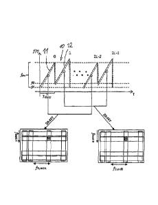
Figure 2 contains a graphical representation of the
profile of a transmission signal, wherein the frequency
of the transmission signal f(t) is plotted against time
CA 02867062 2014-09-11
WO 2013/156012 - 9 -
PCT/DE2013/000154
t. The transmission signal consists of 2 L segments 10,
which foLm two groups A, B of frequency ramps. The
segments 11 of the first group A extend from an initial
value fA over a modulation shift fsw, whereas the
segments 12 of the second group B extend from an
initial value fB with the same modulation shift
(bandwidth) fsw. The segments 11, 12 of groups A, B
adjoin each other alternately, so that all even-
numbered segments belong to group A and all odd-
numbered segments belong to group B.
As in the prior art, a respective evaluation is carried
out for each segment 10, preferably in the form of an
FFT. Using a second evaluation, especially a second
FFT, a range Doppler matrix is formed for the segments
11 of the first group on the one hand and for the
segments 12 of the second group B on the other hand.
there are thus different measured beat frequencies f
¨Beat
A and fseat B for the two matrices.
The transmission signal according to the invention
consists initially of a classic transmission signal,
i.e. of short rapid ramps, with a fixed specified ramp
duration Tchirp. However, the two groups of ramps A and B
are transmitted in a nested "intertwined" mode. Only a
very little changed lower carrier frequency is set
between the first segments (ramps) 11 and the second
segments (ramps) 12, differing e.g. by 10 kHz. Thus in
the first group A in the exemplary embodiment the
transmission signal is modulated from fo to 10 + 100,000
MHz and in the other group of ramps B from fo + 10 kHz
to fo + 100,010 MHz.
The echo signals are mixed with the current
transmission frequency in the baseband. The range
Doppler matrices are generated for the two groups of
ramps A and B. A target or object is accordingly
observed and detected in both groups of ramps A and B
= CA 02867062 2014-09-11
WO 2013/156012 - 10 -
PCT/DE2013/000154
in exactly the same cell of the two range Doppler
matrices (RDM).
Because the Doppler frequency analysis (second FFT) is
carried out for each group of ramps A, i.e. over two
ramp intervals in each case, the already small
uniqueness range of the Doppler frequency in the prior
art is halved again.
However, owing to the measures according to the
invention, this does not result in disadvantages. With
the transmission signal according to the invention and
the two lower carrier frequencies fA = fo and fs = fo +
10 kHz, the two range Doppler matrices for the two
nested signals exist with the following spectra
following the two-dimensional FFT:
k L-1K-1( ZR -127{fBeat D'm
dTchirp2L+,J ¨j271- km .127t1-n
in c
SA(m,n)= E Ee =e K e
1=0 Icr--0
(7)
L-1K-1 [i24f Beat D dTchirP(2I+1)+J B ¨
1
222' __________________________________________________________
e
SB(m,n)= E Ee im = e K
1=0 k=0
(8)
In total 2L ramp signals 11, 12 are transmitted during
this. All even-numbered ramps (group A) are associated
with the signal SA, whereas the signal SE is composed of
the odd-numbered ramps (group B) (2L+1). Compared to
the known arrangement, the initial values fA and fB of
the carrier frequencies in the two groups A, B are
slightly shifted relative to each other. The segments
(ramps) of a group A, B to be processed are separated
from each other by a ramp length Tclurp owing to the
nested arrangement.
In this situation there are two range Doppler matrices,
which are evaluated for specific cells. For detection
CA 02867062 2014-09-11
WO 2013/156012 - 11 - PCT/DE2013/000154
purposes the signals are simply added incoherently by
maynitude for each cell. For each detected target, the
frequency fseat and the ambiguous Doppler frequency f
¨D, md
can be read directly from the range Doppler matrix or
calculated by an interpolation technique for increased
accuracy. In this respect there are two range Doppler
matrices with identical magnitude information (but
different phase information).
According to the invention, the phase difference per
cell in the range Doppler matrix is now evaluated,
advantageously only for those cells in which a target
has been detected.
Mathematically, this is given by
m).[[arg m,
[SA (m,n))
22r = j D ,radTchiri,]mOdg (9)
SB(n)
((f A ¨ f )-2R
27t
fp,ind Tchirp is a phase correction factor that arises
owing to the (possibly ambiguous) measured Doppler
frequency frp,õ(i from ramp to ramp. The phase rotates
further from ramp to ramp by said value. This must be
taken into account for the evaluation of the received
nested signal arrangement. The target distance R and
hence fR can now be calculated from the above equation
and the phase difference measurement as follows:
R= AO c 1 (10)
27r 2 Cf A -fB)
Th fR= f 2R f sw Lc __ 1 ___ fsw
=
AChiT C Tchilp 27r Cf A J.13 TchirP
(11)
CA 02867062 2014-09-11
WO 2013/156012 - 12 - PCT/DE2013/000154
Finally, the unique Doppler frequency fp is given by the
above equation taking into account the measured beat
frequency fBeat and the measured phase difference:
fD fR -1Beat (12)
AT 1 fsw (13)
J Beat
27r (fA ¨fs) fchixp
The evaluation of the measured phase difference results
in a maximum unique measurable distance of
C 1
Rmax 2 2 cfA ¨ fB) (14)
For a frequency difference (fA - fB) of 10 kHz, there is
a maximum unique measurable distance of Rn,aõ = 7.5 km.
For a frequency difference (fA - fB) of 4 kHz there is a
maximum unique measurable distance of Rõ,õ,c - 18.75 km.
Equation 11 thus results in not only an approximate but
an accurate determination of the frequency relating to
the distance R, which according to equations 12 and 13
enables accurate determination of the Doppler frequency
fD in a unique manner.
The use according to the invention of two groups A, B
of segments 11, 12 with nested frequency shifts thus
enables unique and accurate determination of the
distance and the radial velocity by means of the
determination of the Doppler frequency. The described
transmission signal can be generated in the required
manner by a suitably controlled frequency generator.
However, it is also possible that the real segments 10,
CA 02867062 2014-09-11
WO 2013/156012 - 13 -
PCT/DE2013/000154
11 can be generated in the same way, but using a
different virtual modulation. For this purpose,
according to Figure 3 the so-called "zero filling" is
used. The real modulated frequency shift is thereby fsw,
but is not fully utilized. The frequency shift used in
each case for the segments 11, 12 is fsw - (fB - fA).
Figure 3 shows that for the segments 10 a real
modulation is always used, which starts from the
initial value fA and extends over the entire bandwidth
fsw. For the segments 11 of the first group A, the
segment 11 starting with fA is used, whereas at the
upper end a segment of width fB - fA is not used.
For the segment 12 of group B, by contrast, the lower
segment fB - fA is not used, so that the same frequency
shift fsw - (fB - fA) occurs for both segments 11, 12.
According to the version illustrated in Figure 4, the
segments 10 for both groups A, B are generated equally
in real form. The length of the segments here is fsw +
(fB - fA). The real modulated region is thus increased
by fB - fA. Unused sampling values at the upper end of
the seyments 11 of the group A and at the lower end of
the segment 12 of group B are discarded.
In all the described cases, the segments 10, 11 have
the same frequency shift and the same gradient. This is
not absolutely necessary. Different frequency shifts
and different gradients can also be used in the method
described here. However, the mathematical evaluation
for this is somewhat complex.