Note: Descriptions are shown in the official language in which they were submitted.
CA 02867269 2014-09-12
WO 2013/138151 PCT/US2013/029554
DYNAMIC BONE FIXATION ELEMENT
CROSS-REFERENCE TO RELATED APPLICATIONS
[0001] This application claims the benefit of United States Provisional
Application No.
61/609,992 filed March 13, 2012 and United States Provisional Application No.
61/619,072 filed
April 02, 2012 the contents of each of which are hereby incorporated by
reference in their
entirety herein.
BACKGROUND
[0002] Millions of people suffer from bone fractures each year. Treatment of
this
condition is frequently accomplished by rigid fixation which involves affixing
a load carrier (e.g.
a bone plate, a rod, etc.) to a patient's bone fragments via a plurality of
bone fixation elements
(e.g. bone screws, hooks, fixation members, rivets, etc.) in order to
stabilize bone fragments
relative to each other.
[0003] Dynamic fixation of the load carrier is believed to reduce the amount
of stress
generally associated with rigid fixation. In some cases the load carrier is
affixed to the bone
fragments using dynamic locking crews. Certain dynamic locking screws include
a fixation
member that is welded to a sleeve. The sleeves engage bone and the fixation
member is movable
about the weld and relative to the sleeve to thereby allow for micro-movement
of the bone
fragments relative to each other. Known dynamic locking screws may be costly
to manufacture
and may be difficult to manufacture for certain applications. Therefore,
improved dynamic
fixation elements may be desired.
SUMMARY
[0004] In one embodiment, a dynamic bone fixation element is configured to
couple a
load carrier to bone. The dynamic bone fixation element can include a sleeve
that is elongate
along a first direction. The sleeve can define a proximal end, a distal end
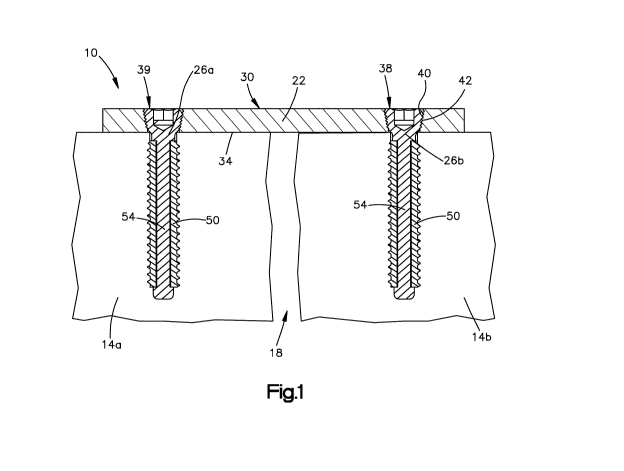
spaced from the
proximal end along the first direction, and a channel that extends from the
proximal end and
toward the distal end along the first direction. The channel can have a first
cross-sectional
dimension measured along a direction that is perpendicular to the first
direction, and the sleeve
can further define an outer surface that is configured to engage bone. The
dynamic bone fixation
element can further include a fixation member having a head, a shaft that
extends from the head
- 1 -
CA 02867269 2014-09-12
WO 2013/138151 PCT/US2013/029554
along a second direction, and an abutment member that extends from the shaft,
wherein the shaft
is configured to extend into the channel such that at least a portion of the
sleeve is captured
between the abutment member and the head to thereby couple the fixation member
to the sleeve.
At least a portion of the shaft that is configured to be within the channel
has a second cross-
sectional dimension along a direction perpendicular to the second direction,
the second cross-
sectional dimension being less than the first cross-sectional dimension such
that the fixation
member is moveable with respect to the sleeve along a direction that has a
directional component
transverse to the first direction.
[0005] In another embodiment, a dynamic bone fixation element can include a
sleeve
that is elongate along a first direction, and a fixation member coupled to the
sleeve. The sleeve
can define a proximal end, a distal end spaced from the proximal end along the
first direction,
and an inner surface that at least partially defines a channel. The channel
can extend from the
proximal end through to the distal end along the first direction. The sleeve
further defines an
outer surface that is configured to engage bone. The fixation member can have
a head, a shaft
extending from the head, and an abutment member extending from the shaft. The
fixation
member is movable with respect to the sleeve along the first direction, and
both the abutment
member and the head define respective abutment surfaces that are sized to
contact the sleeve so
as to limit translation of the fixation member relative to the sleeve along
the first direction.
[0006] In another embodiment, a dynamic bone fixation element can include a
sleeve
that is elongate along a first direction, and a fixation member. The sleeve
defines a proximal
end, a distal end spaced from the proximal end along the first direction, and
an inner surface that
at least partially defines a channel. The channel extends from the proximal
end through to the
distal end along the first direction. The sleeve further defines an outer
surface that is configured
to engage bone. The fixation member can have a head, a shaft extending from
the head and into
the channel, and an abutment member extending from the shaft. The abutment
member at least
partially couples the fixation member to the sleeve such that both a proximal
end and a distal end
of the fixation member are moveable with respect to the sleeve along a
direction that has a
directional component perpendicular to the first direction.
[0007] Methods of making a dynamic fixation element are also disclosed. In one
embodiment, a shaft of a fixation member is inserted through a channel of a
sleeve along a
longitudinal direction until a first abutment surface of the fixation member
contacts a first end of
the sleeve, the sleeve having an inner surface that at least partially defines
the channel, and an
outer surface that is configured to engage bone, the shaft has a surface that
is spaced apart from
the inner surface when the shaft is inserted into the channel such that the
fixation member can
- 2 -
CA 02867269 2014-09-12
WO 2013/138151 PCT/US2013/029554
move relative to the sleeve along a direction that is transverse to the
longitudinal direction. A
second abutment surface is then coupled to the fixation member such that the
sleeve is captured
between the first and second abutment surfaces.
[0008] Methods of fixing a load carrier across a bone gap defined between
first and
second bone portions is also disclosed. In one embodiment the method includes
coupling a load
carrier to a first bone portion with a first dynamic fixation element, the
first dynamic fixation
element having a first fixation member and a first sleeve that is captured
between first and
second abutment surfaces of the first fixation member, the first sleeve having
an inner surface
and the first fixation member including a shaft that has a first surface that
is spaced apart from
the inner surface of the first sleeve such that the first fixation member can
move relative to the
first sleeve. The method further includes coupling the load carrier to a
second bone portion with
a second dynamic fixation element, the second dynamic fixation element having
a second
fixation member and a second sleeve that is captured between first and second
abutment surfaces
of the second fixation member, the second sleeve having an second inner
surface and the second
fixation member including a shaft that has a second surface that is spaced
apart from the second
inner surface of the second sleeve such that the second fixation member can
move relative to the
second sleeve.
BRIEF DESCRIPTION OF THE DRAWINGS
[0009] The foregoing summary, as well as the following detailed description of
embodiments of the application, will be better understood when read in
conjunction with the
appended drawings. For the purposes of illustrating the methods, fixation
elements and systems
of the present application, there is shown in the drawings preferred
embodiments. It should be
understood, however, that the application is not limited to the precise
methods, fixation elements,
and systems shown. In the drawings:
[0010] Fig. 1 is a side elevation view of a bone fixation system according to
an
embodiment, the fixation system having a load carrier and at least two dynamic
fixation elements
coupling the load carrier to respective anatomical structures that are
separated by a gap, the
dynamic fixation elements are shown in cross-section for clarity;
[0011] Fig. 2A is a perspective view of a dynamic fixation element according
to an
embodiment, the dynamic fixation element having a sleeve and a fixation member
coupled to the
sleeve, the sleeve defines a distal end, a proximal end, and a channel
extending from the distal
end through to the proximal end, and the fixation member includes a shaft, a
head extending
- 3 -
CA 02867269 2014-09-12
WO 2013/138151 PCT/US2013/029554
from a proximal end of the shaft, and an abutment member extending from a
distal end of the
shaft, such that the sleeve is captured between the head and the abutment
member;
[0012] Fig. 2B is a bottom plan view of the dynamic fixation element shown in
Fig.
2A;
[0013] Fig. 2C is a side elevation view of the dynamic fixation element shown
in Fig.
2A;
[0014] Fig. 2D is a cross-sectional view of the dynamic fixation element shown
in Fig.
2C through the line 2D-2D;
[0015] Fig. 2E is a cross-sectional view of the dynamic fixation element shown
in Fig.
2C through the line 2E-2E;
[0016] Fig. 2F is a cross-sectional view of the dynamic fixation element shown
in Fig.
2C through the line 2F-2F showing a channel of the sleeve in accordance with
another
embodiment;
[0017] Fig. 2G is a cross-sectional view of the dynamic fixation element
showing at
least some of the directions in which the fixation member can move relative to
the sleeve;
[0018] Fig. 2H is a cross-sectional view of the dynamic fixation element with
the
fixation member rotated counter clockwise relative to the sleeve;
[0019] Fig. 21 is a cross-sectional view of a dynamic fixation element shown
in Fig. 2C
through the line 21-21 in accordance with another embodiment;
[0020] Fig. 3 is a cross-sectional view of the dynamic fixation element shown
in Fig.
2D prior to the head of the fixation member being welded to the shaft of the
fixation member to
thereby couple the fixation member to the sleeve;
[0021] Fig. 4 is a side elevation view of a fixation member positioned in a
mold, the
mold being configured to receive a material to thereby form a sleeve between
the head and the
abutment member of the fixation member
[0022] Fig. 5A is a perspective view of a dynamic fixation element in
accordance with
another embodiment, the dynamic fixation element having a sleeve and a
fixation member that
includes an abutment member that comprises four flexible extensions that flex
inward as the
shaft of the fixation member advances through a channel of the sleeve;
[0023] Fig. 5B is a perspective view of the fixation member shown in Fig. 5A;
[0024] Fig. 5C is a side elevation view of the fixation member shown in Fig.
5B;
[0025] Fig. 5D is a cross-sectional view of the fixation member shown in Fig.
5C
through the line 5D-5D;
- 4 -
CA 02867269 2014-09-12
WO 2013/138151 PCT/US2013/029554
[0026] Fig. 6A is a perspective view of a sleeve in accordance with another
embodiment that can be coupled to the fixation member shown in Fig. 5B;
[0027] Fig. 6B is a top plan view of the sleeve shown in Fig. 6A;
[0028] Fig. 6C is a side elevation view of the sleeve shown in Fig. 6A;
[0029] Fig. 6D is a cross-sectional view of the sleeve shown in Fig. 6C
through the line
6D-6D;
[0030] Fig. 7A is a cross-sectional view of a dynamic fixation element in
accordance
with another embodiment, the dynamic fixation element having a sleeve, and a
fixation member
that includes an abutment member that couples the fixation member to the
sleeve such that the
abutment member is fixed along a direction that is perpendicular to a
direction in which the
fixation member extends through the sleeve;
[0031] Fig. 7B is a cross-sectional view of a dynamic fixation element in
accordance
with another embodiment, the dynamic fixation element having a sleeve that
defines a proximal
channel portion and a distal channel portion, and a fixation member that
includes a proximal
shaft portion and a distal shaft portion, the proximal shaft portion being
circular shaped in cross-
section, and the distal shaft portion being polygonal shaped in cross-section;
[0032] Fig. 7C is a cross-sectional view of the dynamic fixation element shown
in Fig.
7B through the line 7C-7C;
[0033] Fig. 7D is a cross-sectional view of the dynamic fixation element shown
in Fig.
7B through the line 7D-7D;
[0034] Fig. 8A is a side elevation view of a sleeve in accordance with another
embodiment, the sleeve including a plurality of flexible legs at a distal end
of the sleeve;
[0035] Fig. 8B is a cross-sectional view of a dynamic fixation element
including the
sleeve shown in Fig. 8A;
[0036] Fig. 9A is a side elevation view of a bone plate and a plurality of
fixation
members that are pre-assembled so as to form a pre-made implant;
[0037] Fig. 9B is a side elevation view of a bone plate and a plurality of
fixation
members that are integrally formed with the bone plate so as to form a pre-
made monolithic
implant;
[0038] Fig. 9C is a side perspective view of a sleeve having a mating feature
configured
to receive a mating end of a screw driver;
[0039] Fig. 9D is a side perspective view of a sleeve having a mating feature
defined by
the channel such that the channel is configured to receive the mating end of
the screw driver;
- 5 -
CA 02867269 2014-09-12
WO 2013/138151 PCT/US2013/029554
[0040] Fig. 9E is a side perspective view of an implant as shown in either
Figs. 9A or
9B being coupled to sleeves that have been driven into respective anatomical
structures; and
[0041] Fig. 10 is a side perspective view of an implant in accordance with
another
embodiment, the implant being coupled to sleeves that have been driven into
respective vertebral
bodies.
DETAILED DESCRIPTION
[0042] Certain terminology is used in the following description for
convenience only
and is not limiting. The words "right", "left", "lower" and "upper" designate
directions in the
drawings to which reference is made. The words "inner" or "distal" and "outer"
or "proximal"
refer to directions toward and away from, respectively, the geometric center
of the implant and
related parts thereof The words, "anterior", "posterior", "superior,"
"inferior," "medial,"
"lateral," and related words and/or phrases are used to designate various
positions and
orientations in the human body to which reference is made and are not meant to
be limiting. The
terminology includes the above-listed words, derivatives thereof and words of
similar import.
[0043] Referring to Fig. 1 a bone fixation system 10 is configured to affix a
first
substrate or anatomical body 14a and a second substrate or anatomical body 14b
relative to teach
other such that micro-movement of the first and second anatomical bodies 14a
and 14b is
permitted. The anatomical bodies 14a and 14b can each be configured as a bone
fragment, soft
tissue, implant, vertebral body, or any alternative structure configured to be
attached to another
anatomical body. In accordance with the illustrated embodiment, the first and
second anatomical
bodies 14a and 14b are configured as first and second bone fragments,
separated by a bone gap,
such as a fracture 18. It should be appreciated, however, that the gap defined
between the first
and second anatomical bodies can be defined by conditions other than
fractures, including
anatomical deformities and gaps defined between implants and bones or soft
tissue or even a gap
(i.e. intervertebral space) defined between adjacent vertebral bodies.
[0044] The bone fixation system 10 can include a load carrier 22, at least one
dynamic
bone fixation element 26, such as a first dynamic bone fixation element 26a
that affixes the load
carrier 22 to the first anatomical body 14a, and at least one bone fixation
element 26 such as a
second dynamic bone fixation element 26b that affixes the load carrier 22 to
the second
anatomical body 14b. The dynamic bone fixation elements 26 are configured to
allow for micro-
movement of the anatomical bodies 14a and 14b relative to each other.
[0045] With continued reference to Fig. 1, the load carrier 22 can be
configured as a
bone plate having an upper surface 30, a lower bone contacting surface 34, and
at least two bone
- 6 -
CA 02867269 2014-09-12
WO 2013/138151 PCT/US2013/029554
fixation holes 38 that extend from the upper surface 30 through to the lower
bone contacting
surface 34. The load carrier further includes respective inner surfaces 40
that define the fixation
holes 38. Each respective inner surface 40 carries a thread 42 that is
configured to engage the
dynamic bone fixation elements 26. In the illustrated embodiment the thread 42
extends
completely around each surface 40, though it should be appreciated that each
thread 42 can
extend partially around each surface 40 so as to define a plurality of
segments of threads. While
the load carrier 22 is illustrated as a bone plate, it should be appreciated
that the load carrier 22
can be configured as a rod or other stabilizing structure as desired.
[0046] Now in reference to Figs. 2A-2E, the dynamic bone fixation element 26
is
described herein as extending horizontally along a longitudinal direction "L"
and lateral direction
"A", and vertically along a transverse direction "T". Unless otherwise
specified herein, the
terms "lateral," "longitudinal," and "transverse" are used to describe the
orthogonal directional
components of various components. It should be appreciated that while the
longitudinal and
lateral directions are illustrated as extending along a horizontal plane, and
that the transverse
direction is illustrated as extending along a vertical plane, the planes that
encompass the various
directions may differ during use. For instance, when the bone fixation system
10 is coupled to
the spine, the transverse direction T extends vertically generally along the
superior-inferior (or
caudal-cranial) direction, while the plane defined by the longitudinal
direction L and the lateral
direction A lies generally in the anatomical plane defined by the anterior-
posterior direction, and
the medial-lateral direction, respectively. Accordingly, the directional terms
"vertical" and
"horizontal" are used to describe the dynamic bone fixation element 26 and its
components as
illustrated merely for the purposes of clarity and illustration.
[0047] As shown in Figs. 1 and 2A-2E, each dynamic bone fixation element 26 is
configured to affix the load carrier 22 to an anatomical structure such as
bone. Each bone
fixation element 26 includes a sleeve 50 and a fixation member 54 coupled to
the sleeve 50. The
fixation member 54 is coupled to the sleeve 50 such that the fixation member
54 is capable of
moving relative to the sleeve 50 along at least one of the transverse
direction, lateral direction,
and longitudinal direction. The fixation member 54 may also be capable of
rotating relative to
the sleeve 50 about an axis that is parallel to the longitudinal direction.
The fixation member 54
can be made from a first material, and the sleeve 50 can be made from a second
material. The
first material can be stiffer than the second material. For example, the first
material can
comprise cobalt chromium and the second material can comprise titanium. It
should be
appreciated, however, that the sleeve 50 and the fixation member 54 can be
made from any
materials as desired.
- 7 -
CA 02867269 2014-09-12
WO 2013/138151 PCT/US2013/029554
[0048] As shown in Fig. 2A, the dynamic bone fixation element 26 is elongate
along a
first direction X1 (e.g. the longitudinal direction L) and has a proximal end
P and a distal end D
spaced apart from the proximal end P along the first direction Xi. The dynamic
bone fixation
element 26, and in particular the fixation member 54 can have an overall
length Li measured
from the proximal end P to the distal end D along the first direction Xi that
is between about 1.0
mm and about 160.0 mm, and for certain embodiments between about 1.0 mm and
about 3.0
mm. It should be appreciated, however, that the dynamic bone fixation element
can have any
length as desired. Therefore, the dynamic bone fixation element 26 can be
configured to affix a
load carrier to different anatomical structures of different sizes. For
example, the dynamic bone
fixation element 26 can be configured to affix a load carrier to the mandible
or the cervical spine.
[0049] As shown in Figs. 2B-2E, the sleeve 50 is elongate along the first
direction Xi
and defines a first or proximal end 58 and a second or distal end 62 spaced
apart from the
proximal end 58 along the first direction Xi. The sleeve 50 can have an
overall length L2 that is
measured from the proximal end 58 to the distal end 62. The sleeve 50 includes
at least an inner
surface 64 that at least partially defines a channel 66 that extends from the
proximal end 58 and
toward the distal end 62 along the first direction Xi such that the channel 66
extends through
both the proximal end 58 and the distal end 62. As shown in Fig. 2E, the
sleeve 50 includes four
surfaces 64 that define the channel 66. Therefore, a cross-section of the
channel 66 is non-
circular. That is, a cross-section of the channel 66 can be polygonal shaped,
such as square
shaped as illustrated. It should be appreciated, however, that the channel 66
can be defined by
any number of inner surfaces 64 and that the cross-section of the channel 66
can have any non-
circular shape, as desired. For example, the cross-section of the channel 66
can be hexagonally
shaped. Moreover, it should be appreciated that a cross-section of each
portion of the channel 66
along the entire length of the channel 66 can be non-circular, or
alternatively a cross-section of
the channel 66 along only a portion of the length of the channel 66 can be non-
circular while a
remaining portion of the length of the channel 66 has a circular cross-
section. Further, it should
be appreciated, that the channel 66 can extend through the proximal end and
toward the distal
end but not through the distal end.
[0050] As shown in Figs. 2D and 2E, the channel 66 has a cross-sectional
dimension Di
that is measured along a direction that is perpendicular to the first
direction Xi. The dimension
Di can be sized such that the channel 66 receives the fixation member 54 and
the fixation
member 54 is moveable within the channel 66 along at least a direction that
has a directional
component that is transverse to the first direction Xi. It should be
appreciated that the dimension
Di can be the same for the entire length of the channel 66 or the dimension Di
can vary along the
- 8 -
CA 02867269 2014-09-12
WO 2013/138151 PCT/US2013/029554
length of the channel 66 so long as the fixation member 54 is capable of
moving within the
channel 66 as described.
[0051] The inner surfaces 64 can each define respective stops 67 that are
configured to
limit the movement of the fixation member 54 within the channel 66. That is,
the stops 67 can
limit the movement of the fixation member relative to the sleeve along the
direction that has a
directional component that is transverse to the first direction Xi. The stops
67 can be portions of
the inner surfaces 64 proximate to the proximal end of the channel 66 or
portions proximate to
the distal end of the channel 66 as shown in Fig. 2D. It should be
appreciated, however, that the
stops 67 can be portions of the inner surfaces 64 disposed anywhere along the
channel 66, or
even the entire inner surfaces 64 of the channel.
[0052] As shown in Figs. 2A-2D, the sleeve 50 further includes an outer
surface 70 that
extends from the proximal end 58 to the distal end 62 along the first
direction Xi. The outer
surface 70 carries a thread 74 that is configured to engage an anatomical
structure such as bone.
It should be appreciated, however, that the thread 74 can be configured to
engage any anatomical
structure as desired. As shown in Fig. 2C, the thread 74 can extend the entire
length of the
sleeve 50 along the first direction Xi. It should be appreciated, however,
that the thread 74 can
extend only partially along the length of the sleeve 50 as desired. Moreover,
it should be
appreciated that the thread 74 can comprise a plurality of segments of threads
that extend around
the sleeve 50 so long as the thread 74 can engage the anatomical structure and
affix the dynamic
bone fixation element 26 to the anatomical structure.
[0053] As shown in Fig. 2D, the sleeve 50 further includes a first or proximal
abutment
surface 76 and a second or distal abutment surface 78 that faces away from the
first abutment
surface 76. The first and second abutment surfaces 76 and 78 are configured to
abut respective
abutment surfaces of the fixation member 54 to thereby limit movement of the
fixation member
54 relative to the sleeve 50 along the first direction Xi. As shown, the first
and second abutment
surfaces 76 and 78 can be the proximal and distal ends 58 and 62,
respectively, of the sleeve 50.
Therefore, the first and second abutment surfaces 76 and 78 can be spaced
apart from each other
by the distance L2 It should be appreciated, however, that portions of the
sleeve 50 can extend
proximal to the first abutment surface 76 and distal to the second abutment
surface 78 such that
the abutment surfaces 76 and 78 are not the proximal and distal ends of the
sleeve 50.
[0054] As shown in Figs. 2C and 2D, the fixation member 54 extends into the
channel
66 of the sleeve 50 and is loosely coupled to the sleeve 50 such that the
fixation member 54 is
moveable relative to the sleeve. The fixation member 54 has a head 80, a shaft
84 extending
distally from the head 80 along a second direction X2, and an abutment member
88 extending
- 9 -
CA 02867269 2014-09-12
WO 2013/138151 PCT/US2013/029554
from the shaft 84. A shown, the abutment member 88 can extend from a distal
end of the shaft
84 such that the sleeve 50 is captured between the head 80 and the abutment
member 88. In this
way, the sleeve 50 is coupled to the fixation member 54. It should be
appreciated, that the
second direction X2 can be parallel to the first direction Xi or can be
angularly offset with respect
to the first direction Xi. It should also be appreciated, that the abutment
member 88 can extend
from a portion of the shaft that is proximal to the distal end of the shaft
84.
[0055] As shown in Figs. 2C and 2D, the head 80 includes a head body 90 that
is
circular in cross section and defines a proximal surface 92, a distal surface
94, and a side surface
96 that tapers inward as the side surface 96 extends from the proximal surface
92 to the distal
surface 94. The tapered side surface 96 carries a thread 98 that is configured
to engage one of
the threads 42 of the load carrier 22 as the dynamic bone fixation element 26
is inserted through
one of the bone fixation holes 38 of the load carrier 22. Once the thread 98
has engaged the
thread 42, the dynamic bone fixation element 26 will be locked to the load
carrier 22. While the
head 80 includes a thread 98 in the illustrated embodiment, it should be
appreciated that the head
can be devoid of threads. Moreover, it should be appreciated that the side
surface 96 can taper
radially outward as the side surface 96 extends from the proximal surface 92
to the distal surface
94, or the side surface 96 can be void of taper and can be substantially
perpendicular to the
proximal and distal surfaces 92 and 94.
[0056] As shown in Fig. 2D, the head 80 further includes a mating member 102
that
extends into the proximal surface 92 of the head 80. The mating member 102 is
configured to
engage a corresponding mating member of a driving tool. The mating member 102
can be a
hexagonal shaped recess 106 that is configured to be engaged by a hexagonal
protrusion of the
driving tool such that as the driving tool is rotated the dynamic bone
fixation element 26 will be
rotated and driven into the anatomical structure. It should be appreciated,
however, that the
mating member 102 can include other configurations as desired, so long as the
mating member
102 can mate with the driving tool to thereby impart rotation to the dynamic
bone fixation
element 26. For example, the mating member 102 can be a slot shaped recess.
[0057] As shown in Fig. 2D, the distal surface 94 of the head 80 extends
radially out
from the shaft 84 so as to define a shoulder 110 that has a first abutment
surface 114. The
shoulder 110 has a cross-sectional dimension D2 measured along a direction
that is perpendicular
to the second direction X2. The cross-sectional dimension D2 of the shoulder
110 is greater than
the cross-sectional dimension Di of the channel 66. As shown in Fig. 2D, the
first abutment
surface 114 faces the first abutment surface 76 of the sleeve 50 and is
configured to abut the first
- 10 -
CA 02867269 2014-09-12
WO 2013/138151 PCT/US2013/029554
abutment surface 76 of the sleeve 50 so as to limit distal movement of the
fixation member 54
relative to the sleeve 50 along the first direction Xi.
[0058] While in the illustrated embodiment, the head 80 is configured to affix
a bone
plate to an anatomical structure, it should be appreciated that the head 80
can have other
configurations to affix other load carriers to an anatomical structure. For
example, the head 80
can be configured to define a channel that receives a spinal rod. In such an
embodiment, the
channel can extend through the head along a direction that is perpendicular to
the second
direction X2 and can have an opening such that the channel can receive the rod
along the second
direction X2. It should be appreciated, however, that the channel can have an
opening such that
the channel can receive the rod along a direction that is perpendicular to the
second direction X2.
[0059] As shown in Fig. 2D, the shaft 84 extends distally from the distal
surface 94 of
the head 80. The shaft 84 can have an overall length L3 that is greater than
or substantially equal
to the overall length L2 between the first and second abutment surfaces of the
sleeve 50.
Therefore, the shaft 84 can be configured to extend completely through the
channel 66 of the
sleeve 50 such that a proximal end of the shaft 84 is proximal to the proximal
end of the channel
66 and a distal end of the shaft 84 is distal to the distal end of the channel
66. It should be
appreciated, however, that in some cases the shaft 84 can have an overall
length L3 that is less
than the overall length L2 of the sleeve 50. For example, in some embodiments
the abutment
member can extend from the shaft such that a portion of the abutment member is
within the
channel 66 of the sleeve 50 (see for example Fig. 5A).
[0060] As shown in Figs. 2D and 2E, the shaft 84 includes at least an outer
surface 120
that faces the inner surface 64 of the channel 66. As shown in Fig. 2E, the
shaft 84 includes four
outer surfaces 120 that each faces a respective inner surface 64 of the
channel 66. Therefore, the
shaft 84 can have a cross-section that is non-circular. That is, a cross-
section of the shaft 84 can
be polygonal shaped, such as square shaped as illustrated. It should be
appreciated, however,
that the shaft 84 can be defined by any number of outer surfaces 120 and that
the cross-section of
the shaft 84 can have any non-circular shape, as desired. For example, the
cross-section of the
shaft 84 and the channel 66 can be hexagonally shaped as shown in Fig. 2H.
Moreover, it should
be appreciated that a cross-section of each portion of the shaft 84 along the
entire length of the
shaft 84 can be non-circular, or alternatively a cross-section of the shaft 84
along only a portion
of the length of the shaft 84 can be non-circular while a remaining portion of
the length of the
shaft 84 has a circular cross-section. Because the shaft 84 is non-circular
and the channel 66 is
non-circular, the sleeve 50 will rotate as the fixation member 54 is rotated.
That is, as the
fixation member 54 is rotated, the outer surfaces 120 of the shaft 84 will
contact the inner
-11-
CA 02867269 2014-09-12
WO 2013/138151 PCT/US2013/029554
surfaces 64 of the sleeve 50 to thereby cause the sleeve 50 to rotate and be
driven into the
anatomical structure. Therefore, the sleeve 50 does not have to be rigidly
coupled (i.e. welded)
to the fixation member 54 in order for the sleeve 50 to rotate as the fixation
member 54 is
rotated. It should be appreciated, however, that in some embodiments the shaft
84 and the
channel 66 can have circular cross-sections. For example, the shaft 84 or the
channel 66 can
include features that engage each other such that as the fixation member 54 is
rotated, the sleeve
50 will rotate.
[0061] As shown in Figs. 2D and 2E, the outer surfaces 120 of the shaft 84
each faces a
respective inner surface 64 of the channel 66 such that respective non-zero
gaps 130 are defined
between the outer surfaces 120 and the inner surfaces 64. As shown, at least a
portion of the
shaft 84 that is within the channel 66 has a cross-sectional dimension D3
measured along a
direction perpendicular to the second direction X2 that is less than the cross-
sectional dimension
Di of the channel 66. Therefore the fixation member 54 is received by the
channel 66 such that
the fixation member 54 is moveable within the channel 66 along at least a
direction that has a
directional component that is transverse to the first direction Xi. In
particular, the fixation
member is moveable relative to the sleeve 50 along a plurality of directions,
each direction of the
plurality of directions having a directional component that is transverse to
the first direction Xi.
It should be appreciated that the dimension D3 can be the same for the entire
length of the shaft
84 or the dimension D3 can vary along the length of the shaft 84 so long as
the fixation member
54 is capable of moving within the channel 66 as described. It should also be
appreciated that
the cross-sectional dimension Di and the cross-sectional dimension D3
preferably are measured
along the same direction.
[0062] In another embodiment and in reference to Fig. 2F, the sleeve 50 can be
configured to restrict movement of the fixation member 54 relative to the
sleeve in one plane.
As shown in Fig. 2F, the sleeve 50 can include two parallel first surfaces 64a
and two parallel
second surfaces 64b that are longer than the first surfaces 64a and together
define a channel 66a.
Therefore, a cross-section of the channel 66a is rectangular shaped. That is,
the channel 66a has
a first cross-sectional dimension D5 that is measured between the first
surfaces 64a along a
direction that is perpendicular to the first direction Xi and a second cross-
sectional dimension D6
that is measured between the second surfaces 64b along a direction that is
perpendicular to both
the first direction and the direction in which the first cross-sectional
dimension D5 is measured.
As shown, the second cross-sectional dimension D6 is greater than the first
cross-sectional
dimension D5.
- 12 -
CA 02867269 2014-09-12
WO 2013/138151 PCT/US2013/029554
[0063] As shown in Fig. 2F, the first cross-sectional dimension D5 of the
channel 66a is
substantially equal to the cross-sectional dimension D3 of the shaft 84, and
the second cross-
sectional dimension D6 of the channel 66a is greater than the cross-sectional
dimension D3 of the
shaft 84. Therefore, the fixation member 54 is moveable relative to the sleeve
50 in a first plane
that is perpendicular to the first direction Xi and is fixed relative to the
sleeve 50 in a second
plane that is perpendicular to both the first direction Xi and the first
plane.
[0064] Referring back to Figs. 2C and 2D, the abutment member 88 extends from
a
distal end of the shaft 84 and includes an abutment member body 160 that is
circular in cross
section and defines a proximal surface 162, a distal surface 164, and a side
surface 166 that
extends from the proximal surface 162 to the distal surface 164. As shown in
Fig. 2D, the
proximal surface 162 of the abutment member 88 extends radially out from the
shaft 84 so as to
define a shoulder 170 that has a second abutment surface 174 that faces the
first abutment
surface 114 of the head 80. The shoulder 170 has a cross-sectional dimension
D4 measured
along a direction that is perpendicular to the second direction X2 that is
greater than the cross-
sectional dimension Di of the channel 66. The second abutment surface 174
faces the second
abutment surface 78 of the sleeve 50 and is configured to abut the second
abutment surface 78 of
the sleeve 50 so as to limit proximal movement of the fixation member 54 along
the first
direction Xi.
[0065] As shown in Fig. 2G, the sleeve 50 is captured between the head 80 and
the
abutment member 88. As shown, at least a portion of the sleeve 50, such as the
entire sleeve 50,
can be captured between the shoulder 110 of the head 80 and the shoulder 170
of the abutment
member 88 such that the fixation member 54 is substantially fixed relative to
the sleeve 50 along
the first direction Xi. The sleeve 50 can also be captured between the
shoulder 110 of the head
80 and the shoulder 170 of the abutment member 88 such that the fixation
member 54 is
moveable relative to the sleeve 50 along the first direction Xi. Therefore,
the first and second
abutment surfaces 114 and 174 can be spaced from each other along the second
direction X2 such
that a length L4 is defined between the first and second abutment surfaces 114
and 174 that is
either substantially equal to or greater than the overall length Li of the
sleeve 50. In cases where
the length L4 is greater than the length Li a variable sized gap can be
defined between at least
one of the sleeve 50 and the head 80 and/or the sleeve 50 and the abutment
member 88 (see for
example Fig. 5A) to thereby permit movement of the fixation member 54 relative
to the sleeve
50 along the first direction Xi.
[0066] Referring to Fig. 2G, the fixation member 54 is coupled to the sleeve
50 such
that the head 80 is moveable along a third direction X3 and the abutment
member 88 is moveable
- 13 -
CA 02867269 2014-09-12
WO 2013/138151 PCT/US2013/029554
along a fourth direction X4. Both the third direction X3 and the fourth
direction X4 have a
directional component that is perpendicular to the first direction Xi. It
could also be said that the
fixation member 54 is coupled to the sleeve 50 such that a proximal end of the
fixation member
54 is moveable along the third direction X3 and a distal end of the fixation
member is moveable
along the fourth direction X4. Therefore, depending on the configuration of
the dynamic bone
fixation element, each portion of the fixation member 54 may be moveable
relative to the sleeve
50. Because the fixation member 54 is moveable along the first direction Xi,
the third direction
X3, and the fourth direction X4 relative to the sleeve 50, the fixation
element 26 has improved
stress dispersion and allows for micro-movement to thereby improve the quality
of the bone
being generated.
[0067] The third and fourth directions X3 and X4 can be substantially the same
direction or directions that are substantially opposite to each other. For
example, when the third
and fourth directions X3 and X4 are substantially the same direction the
fixation member 54
moves relative to the sleeve 50 such that proximal and distal portions of the
shaft 84 contact or
are otherwise limited by stops 67 of the same inner surface 64 of the channel
66. Alternatively,
when the third and fourth directions X3 and X4 are substantially opposite to
each other, the
fixation member 54 moves relative to the sleeve 50 such that a proximal
portion of the shaft 84
contacts or is otherwise limited by a proximal stop 67 of a first inner
surface 64 of the channel 66
and a distal portion of the shaft 84 contacts or is otherwise limited by a
distal stop 67 of a second
inner surface 64 that is opposed to and faces the first inner surface 64. It
should be appreciated,
however, that the fixation member 54 can move such that the shaft 84 flexes
and the head 80
moves relative to the abutment member 88. For example, when in use, the
abutment member 88
may not be moveable and may be limited by the anatomical structure to which
the dynamic bone
fixation element is affixed. In such a case, the shaft 84 may flex and the
head 80 may move
relative to the sleeve 50 and the abutment member 88.
[0068] When the third and fourth directions X3 and X4 are substantially
opposite to each
other, the direction in which the shaft 84 extends (i.e. the second direction
X2) may be angularly
offset with respect to a center axis C of the channel 66. For example, as
shown in Fig. 2G, the
fixation member 54 may be moveable with respect to the sleeve 50 such that
shaft 84 extends at
an angle 0 with respect to the center axis C. The angle 0 can be any angle
between about 0
degrees and about 50 degrees. It should be appreciated however, that the angle
0 may be any
angle as desired and may depend on the size of the shaft 84 and/or the size of
the channel 66.
[0069] The fixation member 54 may also be moveable with respect to the sleeve
50
along the first direction Xi such that a variable gap is defined between the
abutment surface of
- 14 -
CA 02867269 2014-09-12
WO 2013/138151 PCT/US2013/029554
the head 80 and the first abutment surface of the sleeve 50, and between the
abutment surface of
the abutment member 88 and the second abutment surface of the sleeve 50. The
variable angle
gaps can be equal to or greater than zero. Therefore, the fixation member 54
can be moveable
relative to the sleeve 50 along a plurality of directions each direction
having a directional
component that is either perpendicular to or parallel to the first direction
Xi.
[0070] Now referring to Fig. 2H, the fixation member 54 may also rotate
relative to the
sleeve 50 about the central axis C. The fixation member 54 can rotate either
clockwise or
counterclockwise. As shown, because both the shaft 84 and the channel 66 are
polygonal shaped
rotation of the fixation member 54 can be limited. That is, the fixation
member 54 may be
limited to rotating a specified angle relative to the sleeve 50. For example,
the fixation member
54 may be limited to rotating 30 degrees as illustrated. It should be
appreciated, however, that
the fixation member 54 and the sleeve 50 can be configured such that the
fixation member 54
can rotate any angle relative to the sleeve 50 as desired. Therefore, the
fixation member 54 can
have up to six degrees of freedom relative to the sleeve 50.
[0071] In operation and in reference to Fig. 1, the load carrier 22 can be
affixed to first
and second bone portions across a bone gap defined between the first and
second bone portions.
The load carrier 22 can be positioned such that at least one fixation hole 38
is aligned with the
first bone portion 14a, and at least one fixation hole 38 is aligned with the
second bone portion
14b. A first dynamic bone fixation element 26a can be inserted through one of
the fixation holes
38 such that the sleeve 50 engages the first bone portion 14a and the threads
of the head 80
engage the threads of the fixation hole 38. Similarly, a second dynamic bone
fixation element
26b can be inserted through one of the fixation holes 38 such that the sleeve
50 engages the
second bone portion 14b and the threads of the head 80 engage the threads of
the fixation hole
38. By using the dynamic bone fixation elements 26, micro-movement of the
first and second
bone portions 14a and 14b is permitted along multiple directions including the
longitudinal
direction so as to promote fusion of the first and bone portions 14a and 14b.
The first and second
bone portions 14a and 14b can be mandibular bone portions or vertebral bodies
of the cervical
spine. It should be appreciated, however, that the first and second bone
portions 14a and 14b can
be any bone portions or anatomical structures found in a body.
[0072] Now in reference to Figs. 3 and 4, the fixation member 54 can be
coupled to the
sleeve 50 using a variety of manufacturing techniques. In each case, the
fixation member 54 can
be loosely coupled (i.e. not welded) to the sleeve 50. That is, all portions
of the fixation member
54 can be moveable relative to the sleeve 50. For example, both the proximal
end and the distal
end of the fixation member 54 can be moveable with respect to the sleeve 50
along a direction
- 15 -
CA 02867269 2014-09-12
WO 2013/138151 PCT/US2013/029554
that has a directional component perpendicular to the first direction Xi when
the fixation member
54 is coupled to the sleeve 50. It should be appreciated, however, that in
use, a distal portion of
the fixation member 54 may be fixed relative to the sleeve 50.
[0073] As shown in Fig. 3, the fixation member 54 can be initially formed such
that the
head 80 is separate from an integrally formed or otherwise monolithic shaft 84
and abutment
member 88. To assemble the dynamic bone fixation element 26, the shaft 84 can
be inserted into
a distal end of the channel 66 and translated along the longitudinal direction
L toward the
proximal end of the channel 66 until the abutment surface 174 abuts the second
abutment surface
68 of the sleeve 50. Once inserted, the head 80 having the abutment surface
114 can be coupled
to the proximal end of the shaft 84 by a weld to thereby capture the sleeve 50
between the
abutment surfaces 114 and 174 of the head 80 and the abutment member 88,
respectively. It
should be appreciated, however, that the dynamic bone fixation element 26 can
be assembled
other ways so long as the shaft 84 is integrally formed with a first abutment
surface and a second
abutment surface can be coupled to the shaft at a later time. For example, it
should be
appreciated that the head 80 and the shaft 84 can be integrally formed while
the abutment
member 88 is separate. In such a case, the shaft 84 is inserted through a
proximal end of the
channel 66 and translated along the longitudinal direction L toward the distal
end of the channel
66 until the abutment surface 114 abuts the first abutment surface 76 of the
sleeve 50. Once
inserted, the abutment member 88 having the abutment surface 174 can be
coupled to the distal
end of the shaft 84 by a weld. It should also be appreciated that the head 80
or the abutment
member 88 can be coupled to the shaft 84 without using a weld. For example,
the head 80 or the
abutment member 88 can be coupled to the shaft 84 with a locking or snap
feature formed on the
head 80, the shaft 84, and/or the abutment member 88.
[0074] As shown in Fig. 4, the sleeve 50 can also be overmolded onto the
fixation
member 54. In such a case, the fixation member 54 can be monolithic or
otherwise integrally
formed as a single unit and the sleeve 50 can be overmolded onto the shaft 84.
That is, the head
80, the shaft 84, and the abutment member 88 can be integral to each other and
the sleeve 50 can
be overmolded onto the shaft 84 using a mold 200. As shown in Fig. 4, the mold
200 can
include an upper die and a lower die 204. One of the dies may be moveable with
respect to the
other, or both dies may be movable with respect to teach other. The upper and
lower dies can be
identically constructed unless otherwise indicated, such that the mold can be
formed by inverting
the upper die and joining the upper ide with the lower die 204. Accordingly,
though the lower
die 204 is described in detail herein, it should be appreciated that the
descriptions of the lower
die 204 applies to the upper die unless otherwise indicated.
- 16 -
CA 02867269 2014-09-12
WO 2013/138151 PCT/US2013/029554
[0075] The lower die 204 includes a top surface 208 that defines an engagement
surface
212 configured to engage the complementary engagement surface of the upper
die. The lower
die 204 further defines a pocket 216 that extends from the engagement surface
212 vertically into
the die 204. The pocket 216 is configured to receive the shaft 84 and defines
a portion such as a
first half of the sleeve 50 surrounding half of the shaft 84. As shown, the
pocket 216 has an
outer wall 218 that is shaped to correspond to the shape of the outer wall of
the sleeve 50. The
pocket 216 of the lower die 204 can be combined with the complementary pocket
of the upper
die to form a corresponding mold cavity when the dies are brought together.
The mold cavity
can define the sleeve 50 around the entire shaft 84.
[0076] The lower die 204 further includes at least one injection conduit
section 230
having a channel 234 that defines a terminal end defining an injection port
238 that extends
through the outer wall 218 of the pocket 216. The channel 234 is configured to
receive a mold
material and direct the mold material into the cavity formed by the upper and
lower dies. The
injection molding material conforms to the shaft and the pockets to thereby
form the sleeve 50 as
described above.
[0077] To ensure that a gap is formed between the outer surfaces of the shaft
84 and the
inner surfaces of the channel 66 of the sleeve 50, a filler material 220 can
be disposed between
the shaft and the die 204. For example, the filler material 220 can be a wax
disposed on the shaft
84 that can be subsequently removed after the sleeve 50 has been formed to
thereby permit the
fixation member 54 to move within the channel 66 of the sleeve 50. It should
be appreciated,
however, that the filler material can have other configurations. For example,
the filler material
can be sand.
[0078] It should be appreciated that the fixation element 26 can be
manufactured using
any technique as desired. For example, the sleeve 50 can also be formed or
otherwise coupled to
the fixation member 54 through 3-D metal printing, such as selective laser
sintering. A selective
laser sintering system can include a high power laser such as a carbon dioxide
laser that is
configured to fuse small particles of metal into a mass that has a desired 3-D
shape (i.e. the shape
of the sleeve 50). Therefore, to form the sleeve 50, a digital file containing
a 3-D description of
the sleeve 50 can be downloaded or otherwise transferred to the system. As the
process begins, a
thin first layer of powdered material can be spread across a build platform of
the system. Then
using data from the 3-D digital description, the laser will selectively draw a
cross section of the
sleeve 50 on the first layer of powdered material. As the laser draws the
cross-section, it
selectively sinters (heats and fuses) the powdered material to thereby create
a solid mass that
- 17 -
CA 02867269 2014-09-12
WO 2013/138151 PCT/US2013/029554
represents a first cross-section of the sleeve 50. The system continues this
process until the
sleeve 50 is complete.
[0079] Now in reference to Figs. 5A-5D, the fixation member can be constructed
such
that the dynamic bone fixation element 26 can be assembled manually without
the use of a mold
or weld. As shown in Figs. 5A-5D, a dynamic bone fixation element 326 includes
a sleeve 350
and a fixation member 354 loosely coupled to the sleeve 350. The sleeve 350
and the fixation
member 354 are identical to the sleeve 50 and the fixation member 54 shown in
Figs. 2A-2E and
include like structure unless otherwise described. Moreover, the dynamic bone
fixation element
326 operates and functions in a similar manner as the dynamic bone fixation
element 26 unless
otherwise described.
[0080] As shown in Fig. 5A the sleeve 350 is elongate along the first
direction Xi and
defines a first or proximal end 358 and a second or distal end 362 spaced
apart from the proximal
end 358 along the first direction Xi. The sleeve 350 can have an overall
length L2 that is
measured from the proximal end 358 to the distal end 362 along the first
direction Xi. The
sleeve 350 includes an inner surface 364 that at least partially defines a
channel 366 that extends
from the proximal end 358 toward the distal end 362 along the first direction
Xi such that the
channel 366 extends through both the proximal end 358 and the distal end 362.
As shown, the
channel 366 has a cross-sectional dimension Di that is measured along a
direction that is
perpendicular to the first direction Xi. The dimension Di of the channel 366
can receive the
fixation member 354 such that the fixation member 354 is moveable within the
channel 366
along at least a direction that has a directional component that is transverse
to the first direction
Xi.
[0081] As shown, the sleeve 350 further includes a first or proximal abutment
surface
376 and a second or distal abutment surface 378 that faces a way from the
first abutment surface
376. The first and second abutment surfaces 376 and 378 are configured to abut
respective
abutment surfaces of the fixation member 354 to thereby limit movement of the
fixation member
354 relative to the sleeve 350 along the first direction Xi. As shown, the
first and second
abutment surfaces 376 and 378 can be the proximal and distal ends 358 and 362,
respectively, of
the sleeve 350. Therefore, the first and second abutment surfaces 376 and 378
can be spaced
apart from each other by the length L2 along the first direction Xi. It should
be appreciated,
however, that portions of the sleeve 350 can extend proximal to the first
abutment surface 376
and distal to the second abutment surface 378 such that the abutment surfaces
376 and 378 are
not the absolute proximal and distal ends of the sleeve 350.
- 18 -
CA 02867269 2014-09-12
WO 2013/138151 PCT/US2013/029554
[0082] As shown in Fig. 5A, the fixation member 354 extends through the
channel 366
of the sleeve 350 along the first direction Xi. As shown in Figs. 5B and 5C,
the fixation member
354 has a head 380, a shaft 384 extending distally from the head 380 along a
second direction
X2, and an abutment member 388 extending from the shaft 384. As shown, the
abutment
member 388 can extend from a distal end of the shaft 384 such that at least a
portion of the
abutment member 388 extends along a direction that is perpendicular to the
second direction X2
and the sleeve 350 is captured between the head 380 and the abutment member
388. In this way,
the sleeve 350 is coupleable to the fixation member 354.
[0083] As shown in Figs. 5B and 5C, the head 380 includes a head body 390 that
is
circular in cross section and defines a proximal surface 392, a distal surface
394, and a side
surface 396 that tapers inward as the side surface 396 extends from the
proximal surface 392 to
the distal surface 394. The tapered side surface 396 carries a thread 398 that
is configured to
engage one of the threads 42 of the load carrier 22 as the dynamic bone
fixation element 326 is
inserted through one of the bone fixation holes 38 of the load carrier 22.
Once the thread 398 has
engaged the thread 42, the dynamic bone fixation element 326 will be locked to
the load carrier
22.
[0084] As shown in Figs. 5A and 5C, the distal surface 394 of the head 380
extends
radially out from the shaft 384 so as to define a shoulder 410 that has a
first abutment surface
414. The shoulder 410 has a cross-sectional dimension D2 measured along a
direction that is
perpendicular to the second direction X2. The cross-sectional dimension D2 of
the shoulder 410
is greater than the cross-sectional dimension Di of the channel 366. As shown
in Fig. 5A, the
first abutment surface 414 faces the first abutment surface 376 of the sleeve
350 and is
configured to abut the first abutment surface 376 of the sleeve 350 so as to
limit distal movement
of the fixation member 354 along the first direction Xi.
[0085] As shown in Fig. 5C, the shaft 384 extends distally from the distal
surface 394
of the head 380. The shaft 384 includes at least an outer surface 420 that
faces the inner surface
364 of the channel 366. Like the dynamic bone fixation element 26, the
fixation member 354
and the sleeve 350 are configured such that as the fixation member 354 is
rotated, the outer
surfaces 420 of the shaft 384 will contact the inner surfaces 364 of the
sleeve 350 to thereby
cause the sleeve 350 to rotate and be driven into the anatomical structure.
Therefore, the sleeve
350 does not have to be rigidly connected (i.e. welded) to the fixation member
354.
[0086] As shown in Fig. 5A, the outer surfaces 420 of the shaft 384 each face
a
respective inner surface 364 of the channel 366 such that respective non-zero
gaps 430 are
defined between the outer surfaces 420 and the inner surfaces 364. Therefore,
at least a portion
- 19 -
CA 02867269 2014-09-12
WO 2013/138151 PCT/US2013/029554
of the shaft 384 that is within the channel 366 has a cross-sectional
dimension D3 measured along
a direction perpendicular to the second direction X2 that is less than the
cross-sectional
dimension Di of the channel 366. Therefore the fixation member 354 is received
by the channel
366 such that the fixation member 354 is moveable within the channel 366 along
at least a
direction that has a directional component that is transverse to the first
direction Xi. In
particular, the fixation member 354 is moveable relative to the sleeve 350
along a plurality of
directions, each direction of the plurality of directions having a directional
component that is
transverse to the first direction Xi. It should be appreciated that the
dimension D3 can be the
same for the entire length of the shaft 384 or the dimension D3 can vary along
the length of the
shaft 384 so long as the fixation member 354 is capable of moving within the
channel 366 as
described.
[0087] As shown in Figs. 5A-5D, the abutment member 388 extends from a distal
end
of the shaft 384 and includes at least one such as four flexible extensions
460 that are separated
from each other by elongate slots 461 and are configured to resiliently flex
inward as the shaft
384 is passed through the channel 366 during assembly of the dynamic bone
fixation element
326. Each flexible extension 460 includes an elongate body 462 and a shelf 464
that extends
radially outward from a distal portion of the body 462 along a direction that
is perpendicular to
the second direction. The shelves 464 together define a shoulder 470 that has
a second abutment
surface 474 that faces the first abutment surface 414 of the head 380. The
abutment member 388
or at least the shoulder 470 has a cross-sectional dimension D4 measured along
a direction that is
perpendicular to the second direction X2 that is greater than the cross-
sectional dimension Di of
the channel 366. The second abutment surface 474 faces the second abutment
surface 378 of the
sleeve 350 and is configured to abut the second abutment surface 378 of the
sleeve 350 so as to
limit proximal movement of the fixation member 354 along the first direction
Xi.
[0088] As shown in Fig. 5C each shelf 464 further includes an outer surface
468 that
tapers inward from a proximal surface of the shelf 464 to a distal surface of
the shelf 464. Each
tapered surface 468 is configured to engage the inner surfaces 364 of the
channel 366 to thereby
force the flexible extensions 460 inward as the shaft 384 is passed through
the channel 366. It
should be appreciated, however, that the outer surfaces 468 do not have to be
tapered and can
have other configurations as desired. For example, the outer surfaces 468 can
be perpendicular
to the proximal surface of the shelf 464.
[0089] As shown in Fig. 5A, at least a portion such as the entire sleeve 350
is captured
between the shoulder 410 of the head 380 and the shoulder 470 of the abutment
member 388
such that the portion of the sleeve 350 is aligned with the abutment surface
474 of the abutment
- 20 -
CA 02867269 2014-09-12
WO 2013/138151 PCT/US2013/029554
member 388 along the first direction. As shown, the sleeve 350 can be captured
between the
shoulder 410 of the head 380 and the shoulder 470 of the abutment member 388
such that the
fixation member 354 is moveable relative to the sleeve 350 along the first
direction Xi, or the
sleeve 350 can be captured between the shoulder 410 of the head 380 and the
shoulder 470 of the
abutment member 388 such that the fixation member 354 is substantially fixed
relative to the
sleeve 350 along the first direction Xi. Therefore, the first and second
abutment surfaces 414
and 474 can be spaced from each other along the second direction X2 such that
a length Lc3 is
defined between the first and second abutment surfaces 414 and 474 that is
either substantially
equal to or greater than the overall length L2 between the first and second
abutment surfaces 376
and 378 of the sleeve 350.
[0090] As shown in Fig. 5A, in cases where the length Lc3 is greater than the
length L2
a variable sized gap 480 can be defined between at least one of the sleeve 350
and the head 380
and/or the sleeve 350 and the abutment member 388. In particular, the variable
sized gaps 480
can be defined between the abutment surface of the head 380 and the first
abutment surface 376
of the sleeve 350, and/or the abutment surface of the abutment member 388 and
the second
abutment surface 378 of the sleeve 350. The variable sized gaps 480 can be
measured along a
direction that is parallel to the first direction Xi and can vary between
about 0 mm and about 0.4
mm. It should be appreciated, however, that the variable sized gaps 480 can
vary between any
desired distances. It should be further appreciated, that when the gap 480
between the head 380
and the sleeve 350 decreases, the gap 480 between the abutment member 388 and
the sleeve 350
increases, and vice versa.
[0091] The fixation member 354 is coupled to the sleeve 350 by inserting the
abutment
member 388 into a proximal end of the channel 366 such that the tapered
surfaces 468 of the
shelves 464 contact the inner surfaces 364 of the channel to thereby flex or
otherwise force the
flexible extension inward from a first position to a flexed second position.
The flexible
extensions 460 will remain flexed as the shaft 384 is passed through the
channel 366. Once the
shelves 464 have passed through the channel 366 and are distal to the sleeve
350, the flexible
extensions 460 will return to the first position or at least substantially
close to the first position so
as to capture the sleeve 350 between the first and second abutment surfaces
414 and 474.
Therefore the abutment member 388 can define an outer surface that has a first
cross-section
dimension along the second direction when the abutment member 388 is in the
channel 366, and
the outer surface can define a second cross-sectional dimension along the
second direction that is
greater than the first cross-sectional dimension when the abutment member 388
is distal to the
- 21 -
CA 02867269 2014-09-12
WO 2013/138151 PCT/US2013/029554
channel 366. Therefore, the abutment member 388 is resilient such that the
outer surface is
compressed when in the channel 366 and expanded when distal to the channel
366.
[0092] Now in reference to Figs. 6A-6D, a sleeve 550 constructed in accordance
with
another embodiment can be configured to be loosely coupled to a fixation
member, such as
fixation member 354. As shown in Fig. 6A the sleeve 550 is elongate along the
first direction X1
and defines a first or proximal end 558 and a second or distal end 562 spaced
apart from the
proximal end 558 along the first direction Xi. The sleeve 550 can have an
overall length L2 that
is measured from the proximal end 558 to the distal end 562 along the first
direction Xi. The
sleeve 550 includes a channel 565 that extends from the proximal end 558 and
toward the distal
end 562 along the first direction Xi. In particular the sleeve 550 includes a
first inner surface
564 that at least partially defines a first portion 566 of the channel 565,
and a second inner
surface 568 that at least partially defines a second portion 570 of the
channel 565 that extends
from a distal end of the first portion 566 and toward the distal end 562 along
the first direction
Xi. Therefore it can be said that the channel 565 includes first and second
portions 566 and 570.
As shown, the first portion 566 of the channel 565 has a cross-sectional
dimension D7 that is
measured along a direction that is perpendicular to the first direction Xi and
the second portion
570 of the channel 565 has a second cross-sectional dimension D8 that is also
measured along a
direction that is perpendicular to the first direction Xi and is greater than
the cross-sectional
dimension of the first portion 566 of the channel 565.
[0093] The first portion 566 of the channel 565 has a length Lci along the
first direction
Xi and the second portion 570 of the channel 565 has a second length Lc2 along
the first
direction. The length Lci and the dimension D7 of the first portion 566 is
configured so that the
channel 565 can receive the fixation member 354 such that the fixation member
354 is moveable
within the channel 566 along at least a direction that has a directional
component that is
transverse to the first direction Xi. The dimension D8 of the second portion
570 of the channel
565 is configured such that the second portion 570 can receive the shelves 464
of the fixation
member 354 so as to couple the fixation member 354 to the sleeve 550. The
dimension D8 can
be large enough to allow the distal end of the fixation member 354 to move
along a direction that
is perpendicular to the first direction Xi.
[0094] As shown in Fig. 6B, the sleeve 550 includes four surfaces 564 that
define the
first portion 566. Therefore, a cross-section of the first portion 566 is non-
circular. That is, a
cross-section of the first portion 566 can be polygonal shaped, such as square
shaped as
illustrated. It should be appreciated, however, that the first portion 566 can
be defined by any
number of inner surfaces 564 and that the cross-section of the first portion
566 can have any non-
- 22 -
CA 02867269 2014-09-12
WO 2013/138151 PCT/US2013/029554
circular shape, as desired. For example, the cross-section of the first
portion 566 can be
hexagonally shaped. Moreover, it should be appreciated that a cross-section of
each portion of
the first portion 566 along the entire length of the first portion 566 can be
non-circular, or
alternatively a cross-section of the first portion 566 along only a portion of
the length of the first
portion 566 can be non-circular while a remaining portion of the length of the
first portion 566
has a circular cross-section.
[0095] The shelves 464 can be received by the second portion 570 such that the
fixation
member 354 is fixed in the first direction, or the shelves 464 can be received
by the second
portion 570 such that fixation member 354 is moveable within the channel 565
along the first
direction. For example, the sleeve 550 further includes a first or proximal
abutment surface 576
and a second or distal abutment surface 578 that are configured to abut
respective abutment
surfaces of the fixation member 354 to thereby limit movement of the fixation
member 354
relative to the sleeve 550 along the first direction Xi. As shown, the first
and second abutment
surfaces 376 and 378 can be the proximal and distal ends 358 and 362,
respectively, of the
second portion 570. That is, the first and second abutment surfaces 576 and
578 can at least
partially define the second portion 570 and oppose each other along the first
direction.
Therefore, the first and second abutment surfaces 376 and 378 can be spaced
apart from each
other by the second length Lc2 along the first direction Xi. The shelves 464
of the abutment
member 388 can have a length Lm along the first direction X1 that is less than
the second length
Lc2 to thereby allow the fixation member 354 to move along the first direction
Xi.
[0096] As shown in Fig. 6C, the sleeve 550 further includes an outer surface
580 that
extends from the proximal end 558 to the distal end 562 along the first
direction Xi. The outer
surface 580 carries a thread 582 that is configured to engage an anatomical
structure such as
bone. It should be appreciated, however, that the thread 582 can be configured
to engage any
anatomical structure as desired. As shown in Fig. 6C, the thread 582 can
extend the entire length
of the sleeve 550 along the first direction Xi. It should be appreciated,
however, that the thread
582 can extend only partially along the length of the sleeve 550 as desired.
Moreover, it should
be appreciated that the thread 582 can comprise a plurality of segments of
threads that extend
around the sleeve 550 so long as the thread 582 can engage the anatomical
structure and affix the
dynamic bone fixation element to the anatomical structure.
[0097] As shown in Fig. 6C, the sleeve can further include cutting flutes 586
proximate
to the distal end 562. Therefore as the fixation element is rotated the
cutting flutes 586 will cut
into the anatomical structure to thereby advance the sleeve 550 into the
anatomical structure.
-23 -
CA 02867269 2014-09-12
WO 2013/138151 PCT/US2013/029554
[0098] The fixation member 354 can be coupled to the sleeve 550 by inserting
the
abutment member 388 into a proximal end of the channel 565 such that the
tapered surfaces 468
of the shelves 464 contact the inner surfaces 564 of the first portion 566 of
the channel 365 to
thereby resiliently flex or otherwise force the flexible extensions inward
from a first position to a
flexed second position. The flexible extensions 460 will remain flexed as the
shaft 384 is passed
through the first portion 566. Once the shelves 464 have passed through the
first portion 566 and
into the second portion 570, the flexible extensions 460 will return to the
first position or at least
substantially close to the first position so as to capture the sleeve 550
between at least the
abutment surface 474 and the head 380. Depending on the length Lc2 of the
second portion 570,
the length of the shaft 384, and the length LM of the shelves 464, the
fixation member 354 may
be configured to move along the first direction.
[0099] The abutment surfaces 576 and 578 can be configured to limit the
movement of
the fixation member 354 along the first direction. It should be appreciated,
however, that in
some embodiments the proximal end of the sleeve 550 can define an abutment
surface. In such
embodiments, the proximal end of the sleeve 550 and the proximal abutment
surface 576 are
configured to limit the movement of the fixation member 354 along the first
direction.
Therefore, it can be said that at least a portion of the sleeve 550 is
captured between the
abutment surface 474 of the abutment member 388 and the head 380 along the
first direction Xi.
In embodiments where the captured portion of the sleeve 550 defines a first
length (i.e. the length
Lci of the first portion 566), and the fixation member 354 defines a second
length (i.e. Lc3)
between the head 380 and the abutment surface 474 of the abutment member 388
that is greater
than the first length, the fixation member may be moveable along the first
direction Xi.
[0100] In another embodiment and in reference to Fig. 7A, a dynamic fixation
element
626 can include a sleeve 50 and a fixation member 654 coupled to the sleeve
such that a
proximal end of the fixation member 654 is moveable relative to the sleeve 50
while a distal end
is fixed. The fixation member 654 is identical to the fixation member 354
shown in Figs. 5A-5D
and includes like structure unless otherwise described. Moreover, the dynamic
bone fixation
element 626 operates and functions in a similar manner as the dynamic bone
fixation element
326 unless otherwise described.
[0101] As shown in Fig. 7A, the fixation member 654 extends through the
channel 66
of the sleeve 50 along the first direction Xi and includes a head 680, a shaft
684 extending
distally from the head 680 along a second direction X2, and an abutment member
688 extending
from the shaft 684. As shown, the abutment member 688 can extend from a distal
end of the
shaft 684 such that at least a portion of the abutment member 688 extends
along a direction that
- 24 -
CA 02867269 2014-09-12
WO 2013/138151 PCT/US2013/029554
is perpendicular to the second direction X2 and the sleeve 50 is captured
between the head 680
and the abutment member 688. In this way, the sleeve 50 is coupleable to the
fixation member
654.
[0102] The shaft 684 extends distally from the head 680. The shaft 684
includes at
least an outer surface 720 that faces the inner surface 64 of the channel 66.
As shown in Fig. 7A,
the outer surfaces 720 of the shaft 684 each face a respective inner surface
64 of the channel 66
such that respective non-zero gaps 730 are defined between the outer surfaces
720 and the inner
surfaces 64. Therefore, at least a portion of the shaft 684 that is within the
channel 66 has a
cross-sectional dimension D9 measured along a direction perpendicular to the
second direction
X2 that is less than the cross-sectional dimension D1 of the channel 66.
Therefore the fixation
member 654 is received by the channel 66 such that the head 680 is moveable
relative to the
sleeve 50 along at least a direction that has a directional component that is
transverse to the first
direction X1. In particular, the head 680 is moveable relative to the sleeve
50 along a plurality of
directions, each direction of the plurality of directions having a directional
component that is
transverse to the first direction X1. It should be appreciated, however that
the dimension D9 can
be the same for the entire length of the shaft 684 or the dimension D9 can
vary along the length
of the shaft 684 so long as the head 680 is capable of moving relative to the
sleeve 50 as
described.
[0103] The abutment member 688 extends from a distal end of the shaft 684 and
includes at least one such as four flexible extensions 760 that are separated
from each other by
elongate slots 761 and are configured to resiliently flex inward as the shaft
684 is passed through
the channel 66 during assembly of the dynamic bone fixation element 626. Each
flexible
extension 760 includes an elongate body 762 and a shelf 764 that extends
radially outward from
a distal portion of the body 762 along a direction that is perpendicular to
the second direction.
The shelves 764 together define a shoulder 770 that has a cross-sectional
dimension Dlo
measured along a direction that is perpendicular to the second direction X2
that is greater than the
cross-sectional dimension D1 of the channel 66. Therefore, the abutment member
688 is
configured to limit movement of the fixation member 654 along the first
direction relative to the
sleeve 50.
[0104] With continued reference to Fig. 7A, a portion 790 of the abutment
member 688
that is within the channel 66 has a cross-sectional dimension D11 that is
substantially equal to the
cross-sectional dimension D1 of the channel 66. Therefore, the abutment member
688 can be
fixed relative to the sleeve 50 along a direction that is perpendicular to the
first direction X1.
- 25 -
CA 02867269 2014-09-12
WO 2013/138151 PCT/US2013/029554
Thus it can be said that a distal end of the fixation member 654 can be fixed
relative to the
sleeve, while a proximal end of the fixation member 654 is moveable relative
to the sleeve 50.
[0105] Now in reference to Figs. 7B-7D, and in accordance with another
embodiment,
a dynamic fixation element 826 can include a sleeve 850 and a fixation member
854 coupled to
the sleeve 850 such that a portion of the fixation member 854 is cylindrical
in cross-section and
another portion is polygonal in cross-section. As shown in Fig. 7B, the
fixation member 854 is
coupled to the sleeve 850 in a similar manner as the fixation member 354 shown
in Figs. 5A-5D
is coupled to the sleeve and includes like structure unless otherwise
described.
[0106] As shown in Fig. 7B, the sleeve 850 defines a channel 866 that includes
a
proximal channel portion 866a and a distal channel portion 866b. The proximal
channel portion
866a can define a cross-sectional dimension D12 and the distal channel portion
866b can define a
cross-sectional dimension D13 that is less than that of the proximal channel
portion 866b. As
shown in Figs. 7C and 7D, the proximal channel portion 866a can be circular
shaped in cross-
section and the distal channel portion 866b can be polygonal shaped (e.g.
square shaped,
hexagonal shaped, etc.) in cross-section. It should be appreciated, however,
that the proximal
channel portion 866a and the distal channel portion 866b can have any shape
and dimensions as
desired.
[0107] With continued reference to Figs. 7B-7D, the fixation member 854
extends
through the channel 866 of the sleeve 850 along the first direction Xi and
includes a head 880, a
shaft 884 extending distally from the head 880 along a second direction X2,
and an abutment
member 888 extending from the shaft 884. As shown, the abutment member 888 can
extend
from a distal end of the shaft 884 such that at least a portion of the
abutment member 888
extends along a direction that is perpendicular to the second direction X2 and
the sleeve 850 is
captured between the head 880 and the abutment member 888. In this way, the
sleeve 850 is
coupleable to the fixation member 854 or otherwise trapped by the fixation
member 854.
[0108] As shown in Fig. 7B, the shaft 884 extends distally from the head 880
and the
abutment member 888 extends distally from the shaft 884. As shown in Fig. 7B,
the shaft 884
can define a cross-sectional dimension D14 and the portion of the abutment
member 888 that is
within the channel 866 can define a cross-sectional dimension D15 that is less
than that of the
shaft 884. As shown in Figs. 7C and 7D, the shaft 884 can be circular shaped
in cross-section
and the portion of the abutment member 888 that is within the distal channel
portion 866b can be
polygonal shaped (e.g. square shaped, hexagonal shaped, etc.) in cross-
section. Further, the
dimension D14 of the shaft 884 can be less than the dimension D12 of the
proximal channel
portion 866a such that gaps 930 are formed between an outer surface of the
shaft 884 and an
- 26 -
CA 02867269 2014-09-12
WO 2013/138151 PCT/US2013/029554
inner surface of the sleeve 850 that defines the proximal channel portion
866a. Similarly, the
dimension D13 can be less than the dimension D15 such that gaps 930 are formed
between outer
surfaces of the abutment member 888 and inner surfaces of the sleeve 850 that
define the distal
channel portion 866b. Therefore the fixation member 854 can be received by the
channel 866
such that the head 880 is moveable relative to the sleeve 850 along all
directions having a
directional component that is transverse to the first direction Xi and such
that rotation of the
fixation member 854 causes the sleeve 850 to rotate along with the fixation
member 854.
[0109] Now in reference to Figs. 8A and 8B, a dynamic fixation element 926 can
include a sleeve 950 that defines a plurality of flexible legs 958, and a
fixation member such as
fixation member 54 coupled to the sleeve 950. As shown in Figs. 8A and 8B, the
fixation
member 54 can be identical to the fixation member shown in Figs. 2A-2E, and
the sleeve 950
can be configured such that as the fixation member passes through a channel
966 of the sleeve
950, the flexible legs 958 will flex outward to allow the abutment member to
pass through a
channel 966 of the sleeve 950. It should be appreciated, however, that the
fixation member can
have any configuration as desired. For example, the fixation member can be
similar to the
fixation member 354 shown in Figs. 5A-5D.
[0110] As shown in Figs. 8A and 8B, the sleeve 950 includes a body 952 that is
elongate along the first direction and a channel 966 that extends through the
body 952 along the
first direction. A distal end of the body 952 includes a plurality of cutouts
953 that define the
flexible legs 958. The flexible legs 958 are elastically flexible such that as
the fixation member
954 is passed through the channel 966, the flexible legs 958 will flex
outwardly until the
abutment member 88 of the fixation member 54 has passed through the channel
966. As shown
in Fig. 8A, the channel 966 can have a proximal channel portion 966a and a
distal channel
portion 966b. The proximal channel portion 966a can have a cross-sectional
dimension that is
greater than that of the distal channel portion 966b. For example, the
proximal channel portion
966a can have a cross-sectional dimension that is equal to or greater than the
cross-sectional
dimension D4 of the abutment member 88 so that the abutment member 88 can pass
through the
proximal channel portion 966a.
[0111] The cross-sectional dimension of the proximal portion 966b can be less
than the
cross-sectional dimension D4 of the abutment member 88 such that as the
abutment member 88
passes through the distal channel portion 966b, the abutment member 88 causes
the flexible legs
958 to flex outward so as to allow the abutment member 88 to pass through the
distal channel
portion 966b.
- 27 -
CA 02867269 2014-09-12
WO 2013/138151 PCT/US2013/029554
[0112] With continued reference to Fig. 8A, the sleeve 950 can define a ramped
portion
980 that transitions the proximal channel portion 966a to the distal channel
portion 966b. As the
fixation member 54 is passed through the channel 966, the abutment member 88
will ride against
the ramped portion 980 to thereby cause the flexible legs 958 to flex outward.
When the
abutment member 88 has passed completely through the channel 966 the flexible
legs 958 will
return substantially to their initial position such that the sleeve 950 is
trapped between the
abutment member 88 and the head 80 of the fixation member 54.
[0113] Now in reference to Figs. 9A-9E, a bone fixation system 1010 can
include a
load carrier configured as a bone plate 1022, fixation members 1054 that are
pre-assembled or
otherwise pre-coupled to the bone plate 1022 so as to form an implant 1024,
and corresponding
sleeves 1050 that can receive respective fixation members 1054. The fixation
members 1054 can
be pre-coupled to the bone plate 1022 by inserting the fixation members 1054
through respective
holes of the plate 1022 to thereby form the implant 1024, as shown in Fig. 9A,
or the bone plate
1022 and the fixation members 1054 can be pre-coupled such that the bone plate
1022 and the
fixation members 1054 are integrally formed so as to form a monolithic implant
1054 as shown
in Fig. 9B.
[0114] As shown in Fig. 9C, the sleeves 1050 can include a mating feature 1052
at its
proximal end. Otherwise the sleeve 1050 is constructed in accordance with any
of the previously
described sleeves. The mating feature 1052 can be a slot that is configured to
receive a screw
driver such that rotation of the screw driver will drive the sleeve 1050 into
the anatomical
structure. It should be appreciated, however, that the sleeves 1050 can each
define a channel
1066 that is shaped to receive a driver mating interface 1077 of a driver 1078
such that rotation
of the driver 1078 will cause the sleeve 1050 to rotate as shown in Fig. 9D.
For example, both
the channel 1066 and the mating interface 1077 of the driver can be polygonal
shaped in cross-
section, such as square or hexagonal shaped.
[0115] In operation a drill guide can be placed against the anatomical
structures that are
to be joined by the bone plate 1022 so that holes can be formed in the
anatomical structures.
Once formed, the sleeves 1050 can be driven or otherwise placed in the drilled
holes. The pre-
assembled or otherwise pre-coupled implant can then be coupled to the sleeves
1050. That is the
fixation members 1054 that are pre-coupled to the bone plate 1020 can be
snapped into or
otherwise mated with the sleeves 1050 as shown in Fig. 9E.
[0116] Now in reference to Fig. 10, a bone fixation system 1110 can be
configured as a
spinal fixation system and can include a load carrier that is configured as a
spinal rod 1122 that
can be coupled to a plurality of vertebral bodies V, such as to respective
pedicles of the vertebral
- 28 -
CA 02867269 2014-09-12
WO 2013/138151 PCT/US2013/029554
bodies, or to any other portions of the vertebral bodies as desired. The
system 1110 can further
include a plurality of fixation members 1154 that are pre-assembled or
otherwise pre-coupled to
the spinal rod 1122 so as to form an implant 1124, and corresponding sleeves
1150 that can
receive respective fixation members 1154. The fixation members 1154 can be pre-
coupled to the
spinal rod 1122 by manually assembling the fixation members 1154 to the spinal
rod 1122, or the
spinal rod 1122 and fixation members 1154 can be pre-coupled such that the
spinal rod 1122 and
fixation members 1154 are integrally formed so as to form a monolithic implant
1124. It should
be appreciated that the features of the fixation system 1110 can be
incorporated into any spinal
fixation system, as desired. For example, the features of the fixation system
1110 can be
incorporated in the spinal fixation systems shown in United States Publication
No.
2011/0106166, the contents of which are hereby incorporated by reference
herein.
[0117] In operation a drill guide can be placed against the vertebral bodies V
that are to
be joined by the spinal rod 1122 so that holes can be formed in the vertebral
bodies. Once
formed, the sleeves 1150 can be driven or otherwise placed in the drilled
holes. The pre-
assembled or otherwise pre-coupled implant can then be coupled to the sleeves
1150. That is the
fixation members 1154 that are pre-coupled to the spinal rod 1120 can be
snapped into or
otherwise mated with the sleeves 1150 as shown in Fig. 10.
[0118] The fixation elements can be configured to have a variety of lengths
and thus
can be configured to have variable gaps between the head and the sleeve that
vary from a variety
of maximum gaps. For example, fixation elements as described herein that are
configured to be
attached to a skull or the cranial maxilla facial area can be constructed such
that the maximum
gaps range between about 0.15 mm and about 0.4 mm. That is, a fixation element
having an
overall length of 1 mm can have a channel length of about 0.5 mm, a shaft
length of about 0.35
mm, and a maximum gap of 0.15 mm between the head and the sleeve, a fixation
element having
an overall length of 2.7 mm can have a channel length of about 2.0 mm, a shaft
length of about
1.6 mm, and a maximum gap of 0.2 mm between the head and the sleeve, and a
fixation element
having an overall length of about 5.0 mm can have a channel length of about
3.2 mm, a shaft
length of about 2.6 mm, and a maximum gap of 0.4 mm between the head and the
sleeve.
Therefore it can be said that the fixation element can have an overall length
that is less than 5.0
mm. It should be appreciated, however, that the listed dimensions are for
example only, and the
fixation elements described can have any dimensions as desired.
[0119] It will be appreciated by those skilled in the art that changes could
be made to
the embodiments described above without departing from the broad inventive
concept thereof
Furthermore, it should be appreciated that the structure, features, and
methods as described
- 29 -
CA 02867269 2014-09-12
WO 2013/138151 PCT/US2013/029554
above with respect to any of the embodiments described herein can be
incorporated into any of
the other embodiments described herein unless otherwise indicated. For
example, dynamic bone
fixation element 26 can be constructed such that the gap 480 is defined
between at least one of
the sleeve 50 and the head 80 or the sleeve 50 and the abutment member 88 or
any of the
channels of the sleeves can by completely cylindrical. It should be further
appreciated that the
dynamic bone fixation elements 26 and 326 can be manufactured using any
technique as desired,
and is not limited to those described herein. It is understood, therefore,
that this invention is not
limited to the particular embodiments disclosed, but it is intended to cover
modifications within
the spirit and scope of the present disclosure.
- 30 -