Note: Descriptions are shown in the official language in which they were submitted.
CA 02872238 2014-10-30
WO 2013/164830
PCT/1L2013/050376
1
IN-SITU FORMATION OF A JOINT REPLACEMENT PROSTHESIS
FIELD OF THE INVENTION
The invention relates to in-situ formation of a joint replacement prosthesis.
BACKGROUND OF THE INVENTION
Joint surfaces are subject to damage by injury and inflammation, but most
commonly
by arthritis. Arthritis affects the articular cartilage, sometimes to a degree
which exposes and
roughens the underlying bone surfaces, thereby creating mechanical
interference to the
smooth motion of the joint, severe pain and general joint dysfunction.
One of today's most successful approaches for treating damaged articular
cartilage is
total joint replacement, also referred to as total joint arthroplasty. The
deformed joint surfaces
are resected and replaced by one or more artificial prostheses, re-enabling
smooth and normal
joint motion. In existence today are various techniques for performing total
joint replacement
or related arthoplastic treatments. Some examples are discussed below.
U.S. Patent No. 6,248,131 to Felt et al. discloses a method and related
materials and
apparatus for using minimally invasive means to repair (e.g., reconstruct)
tissue such as
fibrocartilage, and particularly fibrocartilage associated with diarthroidal
and amphiarthroidal
joints. The method involves the use of minimally invasive means to access and
prepare
damaged or diseased fibrocartilage within the body, and to then deliver a
curable biomaterial,
such as a two-part polyurethane system, to the prepared site, and to cure the
biomaterial in
situ in order to repair the fibrocartilage. Applications include repair and
replacement of the
intervertebral disc of the spine.
U.S. Patent No. 6,443,988 to Felt et al. discloses a method, and related
composition and
apparatus for repairing a tissue site. The method involves the use of a
curable polyurethane
biomaterial composition having a plurality of parts adapted to be mixed at the
time of use in
order to provide a flowable composition and to initiate cure. The flowable
composition can
be delivered using minimally invasive means to a tissue site and once
delivered fully cured to
provide a permanent and biocompatible prosthesis for repair of the tissue
site. Further
provided are a mold apparatus, e.g., in the form of a balloon or tubular
cavity, for receiving a
biomaterial composition, and a method for delivering and filling the mold
apparatus with a
curable composition in situ to provide a prosthesis for tissue repair.
U.S. Patent No. 7,758,649 to Walsh et al. discloses an implant for positioning
within a
particularly dimensioned body cavity. The implant is reversibly deformable
between an
CA 02872238 2014-10-30
WO 2013/164830
PCT/1L2013/050376
2
expanded state and a compressed state. The implant is constructed and arranged
for insertion
within the body cavity when in its compressed state, and pressurelessly
conforms to the
cavity dimensions in its expanded state. Particularly, the implant is
characterized by
spontaneous deformation to the expanded state in situ within the body cavity
while retaining
and/or absorbing at least one flowable constituent as a function of its degree
of deformation.
U.S. Patent Application Publication No. 2005/0043808 Felt et al. discloses a
method,
and related composition and apparatus for repairing a tissue site. The method
involves the use
of a curable polyurethane biomaterial composition having a plurality of parts
adapted to be
mixed at the time of use in order to provide a flowable composition and to
initiate cure. The
flowable composition can be delivered using minimally invasive means to a
tissue site and
upon delivery fully cured providing a permanent and biocompatible prosthesis
for repair of
the tissue site. Further provided are a mold apparatus, e.g., in the form of a
balloon or tubular
cavity, for receiving a biomaterial composition, and a method for delivering
and filling the
mold apparatus with a curable composition in situ to provide a prosthesis for
tissue repair.
U.S. Patent Application Publication No. 2005/0229433 to Cachia discloses
methods and
devices for manipulating alignment of the foot to treat patients with flat
feet, posterior tibial
tendon dysfunction and metatarsophalangeal joint dysfunction. An inflatable
implant is
positioned in or about the sinus tarsi and/or first metatarsal-phalangeal
joint of the foot. The
implant is insertable by minimally invasive means and inflatable through a
catheter or needle.
Inflation of the implant alters the range of motion in the subtalar or first
metatarsal-
phalangeal joint and changes the alignment of the foot.
U.S. Patent Application Publication No. 2009/0287309 to Walch et al. discloses
a
method for implanting an intra-articular shoulder prosthesis. The method
includes removing a
proximal portion of a humerus. The proximal portion of the humerus preferably
forms a
resected portion. The resected portion has a convex outer surface and an inner
surface. The
method further includes engaging the convex outer surface of the resected
portion with a cut
surface of the proximal portion of the humerus. The cut surface of the
proximal portion of the
humerus and/or the inner surface of the resected portion are optionally
processed to form a
generally concave surface, such as by impacting. In one embodiment, the inner
surface of the
resected portion is impacted into engagement with the cut surface of the
proximal portion of
the humerus. The generally concave inner surface of the resected portion forms
a concave
articular surface to receive an interpositional implant.
CA 02872238 2014-10-30
WO 2013/164830
PCT/1L2013/050376
3
U.S. Patent Application No. 2010/0241152 to Tilson et al. discloses inflatable
medical
devices and methods for making and using the same. The inflatable medical
devices can be
medical balloons. The balloons can be configured to have a through-lumen or no
through-
lumen and a wide variety of geometries. The device can have a high-strength,
non-compliant,
fiber-reinforced, multi-layered wall. The inflatable medical device can be
used for
angioplasty, kyphoplasty, percutaneous aortic valve replacement, or other
procedures
described herein.
U.S. Patent No. 8,100,979 to Felt. et al. method and system for the creation
or
modification of the wear surface of orthopedic joints, involving the
preparation and use of
one or more partially or fully preformed and procured components, adapted for
insertion and
placement into the body and at the joint site. In a preferred embodiment,
component(s) can be
partially cured and generally formed ex vivo and further and further formed in
vivo at the
joint site to enhance conformance and improve long term performance. In
another
embodiment, a preformed balloon or composite material can be inserted into the
joint site and
filled with a flowable biomaterial in situ to conform to the joint site. In
yet another
embodiment, the preformed component(s) can be fully cured and formed ex vivo
and
optionally further fitted and secured at the joint site. Preformed components
can be
sufficiently pliant to permit insertion through a minimally invasive portal,
yet resilient
enough to substantially assume, or tend towards, the desired form in vivo with
additional
forming there as needed.
Finally, PCT Publication No. W02010/107949 to Nikolchev et al. discloses a
method
for creating space in a joint, the method comprising: applying force to a body
part so as to
distract the joint and create an intrajoint space; inserting an expandable
member into the
intrajoint space while the expandable member is in a contracted condition;
expanding the
expandable member within the intrajoint space; and reducing the force applied
to the body
part so that the joint is supported on the expandable member.
A significant number of orthopedic surgeries are performed today using
minimally-
invasive techniques, such as arthroscopy. In arthroscopic surgery, examination
and
sometimes treatment of the joint are performed by inserting an arthroscope
through a small
incision. Additional surgical instruments may be inserted into the joint via
other small
incisions. Arthroscopy often reduces recovery time and minimizes trauma to
connective
tissue as well as external scarring.
CA 02872238 2014-10-30
WO 2013/164830
PCT/1L2013/050376
4
There is still a need in the art for enhanced surgical methods, devices and
kits for
minimally-invasive joint replacement.
SUMMARY OF THE INVENTION
There is provided, in accordance with some embodiments, a surgical kit for
arthroscopic, in-situ formation of a joint replacement prosthesis, the
surgical kit comprising:
an expandable prosthesis mold configured to be arthroscopically introduced
into a joint; at
least one arthroscopic instrument configured to form an ellipsoidal cavity
between two
interfacing bones of the joint, for receiving said mold; and a first flowable,
curable substance
configured for forming the prosthesis inside said mold.
In some embodiments, said mold is characterized by a smooth, ellipsoidal inner
surface,
such that an outer surface of said prosthesis, when formed, is smooth and
ellipsoidal.
In some embodiments, said ellipsoidal inner surface comprises a spheroidal
inner
surface.
In some embodiments, said spheroidal inner surface comprises a spherical inner
surface.
In some embodiments, said mold is characterized by a final inflated size.
In some embodiments, said mold comprises a balloon made of a rigid material.
In some embodiments, said mold is made of a non-elastic material.
In some embodiments, the surgical kit further comprises an expandable spacer
configured to be arthroscopically introduced into the joint, wherein said
spacer is configured,
when expanded, to maintain the ellipsoidal cavity between the two interfacing
bones at least
during the formation of the prosthesis.
In some embodiments, said mold is provided within said spacer, such that said
mold
and said spacer are configured to be arthroscopically introduced into the
joint together.
In some embodiments, said spacer is characterized by a final inflated size.
In some embodiments, said mold and said spacer, when at their final inflated
size, are
isomorphic.
In some embodiments, said first flowable, curable substance is further
configured for
forming a prosthetic layer over the prosthesis, inside said spacer.
In some embodiments, the surgical kit further comprises a second flowable,
curable
substance configured for forming a prosthetic layer over the prosthesis,
inside said spacer.
CA 02872238 2014-10-30
WO 2013/164830
PCT/1L2013/050376
In some embodiments, said spacer is characterized by a smooth, ellipsoidal
inner
surface, such that an outer surface of said prosthetic layer, when formed, is
smooth and
ellipsoidal.
In some embodiments, the surgical kit further comprises a pumping system
configured
5 to control inflation of said mold.
In some embodiments, the surgical kit further comprises a pumping system
configured
to control injection of said substance into said mold.
In some embodiments, the surgical kit further comprises a pumping system
configured
to control inflation of said spacer.
In some embodiments, the surgical kit further comprises a pumping system
configured
to control injection of at least one of said substance and said different
substance into said
spacer.
In some embodiments, the surgical kit further comprises an arthroscopic
extraction
instrument configured to extract said mold after the prosthesis is formed.
In some embodiments, said arthroscopic extraction instrument is further
configured to
extract said spacer after at least one of the prosthesis and the prosthetic
layer is formed.
In some embodiments, the arthroscopic extraction instrument comprises at least
one
wire, for example, a rigid thin wire. In some embodiments, at least part of
the wire is attached
to a surface of the mold or embedded in the mold. In some embodiments, at
least part of the
wire is attached to a surface of the spacer or embedded in the spacer. In some
embodiments,
the wire is configured to rip at least part of the mold along the path of the
wire upon pulling
said wire. In some embodiments, the wire is configured to rip at least part of
the spacer along
the path of the wire upon pulling said wire.
In some embodiments, the surgical kit further comprises a guide wire
configured to
guide surgical tools into said joint.
In some embodiments, the surgical kit further comprises starter drill
configured to drill
an initial hole in the joint.
In some embodiments, said starter drill comprises an adjustable stopper
configured to
allow drilling up to a preset depth.
In some embodiments, said starter drill comprises a convex end surface.
In some embodiments, the surgical kit further comprises a convex, expandable
reamer
configured to form the ellipsoidal cavity between the two bones.
CA 02872238 2014-10-30
WO 2013/164830
PCT/1L2013/050376
6
In some embodiments, the surgical kit further comprises a guide cannula
configured to
be secured relative to the joint to guide said guide wire into the joint at a
predetermined
angle.
In some embodiments, said guide wire is further configured to guide said
reamer into
the joint at the predetermined angle over said guide wire.
In some embodiments, said reamer is configured, when forming the ellipsoidal
cavity,
to ream one of the two bones.
In some embodiments, said reamer is configured, when forming the ellipsoidal
cavity,
to ream the two bones.
In some embodiments, said arthroscopic guide cannula comprises concave,
collapsible
arms for positioning said guide wire relative to the joint.
In some embodiments, the joint is a ball-and-socket joint and said arms are
configured
to cling to the ball of the ball-and-socket joint.
In some embodiments, said starter drill is a cannulated starter drill.
In some embodiments, said mold comprises a fluid port configured to extend
externally
to the joint when said mold is introduced into the joint.
In some embodiments, said spacer comprises a fluid port configured to extend
externally to the joint when said spacer is introduced into the joint.
In some embodiments, the surgical kit further comprises a file configured to
remove
cured substance protruding from said mold due to curing of the substance in
said fluid port of
said mold.
In some embodiments, said file is further configured to remove cured substance
protruding from said spacer due to curing of the substance in said fluid port
of said spacer.
In some embodiments, the surgical kit further comprises an ultraviolet (UV)
curer for
curing said substance inside said joint.
There is further provided, in accordance with some embodiments, a minimally-
invasive
method for in-situ formation of a joint replacement prosthesis, the method
comprising:
arthroscopically forming an ellipsoidal cavity between two interfacing bones
of the joint; and
arthroscopically forming an ellipsoidal joint replacement prosthesis in the
cavity.
In some embodiments, the forming of said ellipsoidal joint replacement
prosthesis
comprises: arthroscopically introducing an expandable prosthesis mold into
said cavity; and
injecting a first flowable, curable substance into said mold, thereby forming
said ellipsoidal
joint replacement prosthesis inside said mold.
CA 02872238 2014-10-30
WO 2013/164830
PCT/1L2013/050376
7
In some embodiments, the forming of the ellipsoidal cavity comprises reaming
at least
one of the two interfacing bones using a convex, expandable reamer.
In some embodiments, the method further comprises drilling an initial hole in
the joint,
to allow introduction of said convex, expandable reamer into the joint.
In some embodiments, the method further comprises, prior to injecting said
substance:
arthroscopically introducing an expandable spacer into the joint; and
expanding said spacer to
maintain the ellipsoidal cavity between the two interfacing bones at least
during the
formation of the prosthesis.
In some embodiments, said mold is provided within said spacer, such that said
mold
and said spacer are introduced together, arthroscopically, into the cavity.
In some embodiments, the method further comprises forming injecting the first
flowable, curable substance into said spacer, to form a prosthetic layer over
said prosthesis.
In some embodiments, the method further comprises injecting a second flowable,
curable substance into said spacer, to form a prosthetic layer over said
prosthesis.
In some embodiments, the method further comprises extracting said mold after
said
prosthesis is formed.
In some embodiments, the method further comprises extracting said spacer after
said
prosthetic layer is formed.
In some embodiments, the method further comprises applying UV radiation for
curing
said first substance.
In some embodiments, the method further comprises applying UV radiation for
curing
said second substance.
In some embodiments, the method further comprises removing cured substance
protruding from said mold.
In some embodiments, the method further comprises prior to arthroscopically
forming
an ellipsoidal cavity, arthroscopically releasing the joint capsule of the
joint.
There is further provided, in accordance with some embodiments, a corrective
surgical
method comprising modifying a bone being the ball of a ball-and-socket joint
to have a
socket shape, and forming, in-situ, an ellipsoidal prosthesis between said
bone and a different
bone being the socket of said ball-and-socket joint.
There is further provided, in accordance with some embodiments, an expandable
mold
configured to be arthroscopically introduced into a joint for in-situ
formation of a joint
CA 02872238 2014-10-30
WO 2013/164830
PCT/1L2013/050376
8
replacement prosthesis, and a flowable, curable substance configured for
forming the joint
replacement prosthesis inside said mold.
There is further provided, in accordance with some embodiments, a joint
replacement
prosthesis assembly for in-situ formation of a joint replacement prosthesis,
the assembly
comprising a plurality of parts, each being sized so as to enable its
minimally-invasive
introduction into a damaged joint, wherein said plurality of parts are
configured to be
assembled into the joint replacement prosthesis.
In some embodiments, said plurality of parts comprises a core part and
multiple
peripheral parts configured to be mounted onto said core part.
In some embodiments, said plurality of parts comprises a plurality of
similarly-shaped
parts.
In some embodiments, the joint replacement prosthesis assembly further
comprises one
or more securing elements configured to secure said plurality of parts once
assembled.
In some embodiments, said one or more securing elements comprises one or more
bolts.
The present invention further provides, according to some embodiments, an
expandable
prosthesis mold configured to be arthroscopically introduced into a joint;
wherein the mold is
configured to allow in-situ formation of a joint replacement prosthesis within
the mold;
wherein the mold is configured to have a collapsed form and an expanded form;
wherein the
expanded form has a final size; wherein the mold comprises at least one wire,
wherein at least
a part of the wire is attached to a surface of the mold or embedded in the
mold, the wire
having a proximal end and a distal end; and wherein at least part of the mold
is configured to
rip along the path of said wire upon pulling the proximal end of said wire.
In some embodiments, the mold is an inflatable mold. In some embodiments, the
mold
further comprises a string configured to extract the mold from a subject's
body upon pulling
said string.
In some embodiments, the proximal end of said wire is configured to extend
into an
arthroscopic extraction instrument. In some embodiments, the wire is made of a
material
configured to transmit energy, such as, but not limited to an electricity
conducting material.
In some embodiments, the wire is configured to connect into an energy source,
such as, but
not limited to, an electricity source.
CA 02872238 2014-10-30
WO 2013/164830
PCT/1L2013/050376
9
BRIEF DESCRIPTION OF THE FIGURES
Exemplary embodiments are illustrated in referenced figures. Dimensions of
components and features shown in the figures are generally chosen for
convenience and
clarity of presentation and are not necessarily shown to scale. The figures
are listed below.
Fig. 1 shows a healthy human shoulder joint;
Fig. 2 shows a damaged human shoulder joint;
Figs. 3A-B shows the damaged joint and a guide cannula;
Fig. 3Ba shows the damaged joint and a guide wire;
Fig. 3C shows the guide wire and a starter drill used in drilling an initial
bore in the
damaged joint;
Fig. 3D shows the guide wire and a convex, expandable reamer used in resecting
articular matter for forming a cavity in the damaged joint;
Fig. 3E shows a spheroidal cavity formed between the interfacing bones and
within the
bones themselves;
Fig. 3F shows an expandable joint replacement prosthesis mold;
Fig. 4 shows a flow chart of a method for in-situ formation of a joint
replacement
prosthesis;
Figs. 5A-C show a guide cannula in cross-sectional and perspective views with
collapsed (A) and expanded (B, C) securing elements;
Figs. 6A-F show a cannulated starter drill in perspective, side and cross-
sectional views;
Figs. 7A-D show a convex, cannulated expandable reamer in its collapsed form
in front,
cross-sectional, side and isometric views;
Figs. 7E-H show the convex, cannulated expandable reamer in its expanded form
in
front, cross-sectional, side and isometric views;
Figs. 8A-C show cross-sectional views of a joint replacement prosthesis mold
and an
insertion instrument;
Figs. 9A-B show cross-sectional views of the mold and an optional spacer
containing it;
Fig. 10 shows a perspective view of three molds of gradual sizes provided one
inside
the other;
Fig. 11 shows a first exemplary extraction instrument;
Fig. 12 shows a second exemplary extraction instrument;
Figs. 13A-D show a third exemplary extraction instrument;
Figs. 14A-E show a fourth exemplary extraction instrument;
CA 02872238 2014-10-30
WO 2013/164830
PCT/1L2013/050376
Figs. 15A-E show a fifth exemplary extraction instrument; and
Fig. 16 shows another option for a joint replacement prosthesis.
DETAILED DESCRIPTION
5 A
surgical method for arthroscopic, in-situ formation of a joint replacement
prosthesis,
as well as a surgical kit for facilitating the same, are disclosed herein.
Advantageously, the
method may be performed entirely in a minimally-invasive manner, such as using
arthroscopic techniques and instrumentation. An expandable, optionally
inflatable, prosthesis
mold may be arthroscopically introduced into a damaged joint, and a smooth,
ellipsoidal joint
10
replacement prosthesis may then be formed in-situ, by filling the mold with a
suitable
flowable, curable substance. The ellipsoidal mold may be, more specifically,
of a spheroidal
shape, or even more specifically, a spheroid ¨ according to the medical needs.
Optionally, the
prosthesis mold may be an ellipsoid, where the difference between the apogee
and perigee of
the ellipsoid is, for example, about 1 millimeter. Optionally, the prosthesis
mold may be
spherical or a spheroid. Each possibility represents a separate embodiment of
the present
invention. Optionally, the mold is made of a non-elastic material. The mold
may be rigid or
partially rigid (for example, may include rigid parts or may include rigid
parts that may form
a rigid mold when assembles). The mold may be made of a material with zero or
partial
compliance.
The damaged joint may be adapted and/or modified for receiving the prosthesis
mold by
resecting cartilage and/or bone material from one or two of the interfacing
bones of the joint
using arthroscopic instrumentation, to form an ellipsoidal, smooth cavity for
the prosthesis. In
a ball-and-socket type joint, such as the shoulder or the hip joints, the
prosthesis mold
becomes the ball part of the joint, while the humeral or femoral head,
respectively, becomes a
socket. The ellipsoidal joint replacement prosthesis then serves as a ball
interfacing between
the original glenoid or acetabulum socket and the newly-created humeral or
femoral head
socket, respectively, allowing them to slide smoothly on its outer surface.
According to some
embodiments, the prosthesis slides only or mainly against the humerus. Each
possibility
represents a separate embodiment of the present invention. According to other
embodiments,
the prosthesis slides only or mainly against the glenoid. Each possibility
represents a separate
embodiment of the present invention. According to other embodiments, the
prosthesis slides
against both the humerus and the glenoid. According to some embodiments, the
prosthesis
slides against the humerus and/or the glenoid so as long as normal and/or
maximal movement
CA 02872238 2014-10-30
WO 2013/164830
PCT/1L2013/050376
11
range of the joint is maintained. Each possibility represents a separate
embodiment of the
present invention.
It is to be noted, that according to various embodiments of the present
invention, the
cavity and/or joint replacement prosthesis and/or mold may be of an ellipsoid,
spheroid or
spherical shape. Each possibility represents a separate embodiment of the
present invention.
According to some embodiments, the cavity and/or joint replacement prosthesis
and/or mold
may be spherical.
Following the arthroscopic, in-situ formation of the joint replacement
prosthesis, the
prosthesis remains enclosed within the joint capsule and the rest of the soft
tissues, namely,
tendons, ligaments and/or the muscles around the joint. The tension of the
soft tissues may
keep the new joint replacement prosthesis in place. However, the area that is
reamed from the
bone may become covered with new fibrocartilage which articulates with the new
ball joint.
Advantageously, as discussed above, the method is performed arthroscopically,
optionally without cutting any tendons or muscles in order to get into the
joint. Therefore,
applying the method eliminates the need to protect or repair tendons and
muscles following
the procedure. Thus, recovery from the present joint replacement procedure is
extremely
short. In fact, immediately following the procedure, a patient can start with
a mobilization
and rehabilitation exercise program. Thus, the procedure provides accelerated
rehabilitation
and recovery, which are much shorter than rehabilitation and recovery after
standard joint
replacement procedures.
The aforementioned advantages render the method suitable for ambulatory
surgery
centers (also known as "outpatient surgery centers" or "same-day surgery
centers").
Reference is now made to Fig. 1, which shows a schematic illustration of a
healthy
human shoulder joint 100. The shoulder joint is used as a demonstrative joint
throughout the
disclosure only for reasons of simplicity; the various discussions made with
reference to this
demonstrative joint apply, mutatis mutandis, to other mammalian joints, such
as the hip,
knee, wrist, ankle, metacarpophalangeal, metatarsophalangeal, interphalangial
joint and
others. Shoulder joint 100 exhibits smooth, healthy joint surfaces: a humerus
head 102 and its
cartilage cover 104, as well as a glenoid cavity 106 and its cartilage cover
108, are all shown
essentially intact.
Fig. 2 shows a schematic illustration of a representative damaged joint, a
human
shoulder joint 200. The damage to the various parts of damaged joint 200 is
shown by way of
example; in practice, joint damage may be exhibited in various patterns of
articular surface
CA 02872238 2014-10-30
WO 2013/164830
PCT/1L2013/050376
12
deformation. The term "articular surface" (or "joint surface"), as referred to
herein, may
relate to the external surface of the cartilage cover of each of the bones of
a joint. The
external surface of the bone, which is either exposed or still covered by
cartilage, may also be
referred to as an articular surface; its relevancy arises in cases where
cartilage damage causes
a bone to be partially exposed.
A cartilage cover 204 of a humerus head 202 is shown damaged, and so is a
cartilage
cover 208 of a glenoid cavity 206. Pain may be caused as cartilage covers 204
and 208
contact each other during joint motion. Worse, exposed areas 210 of humerus
head 202
and/or exposed areas 212 of glenoid cavity 206 may also come in contact with
one another
and/or with an opposing cartilage cover, causing further damage.
Reference is now made to Figs. 3A-B which schematically illustrate damaged
joint 200
and a first, optional element of a surgical kit, during at least a stage of
the present surgical
method for in-situ formation of a joint replacement prosthesis (the method
also referred to as
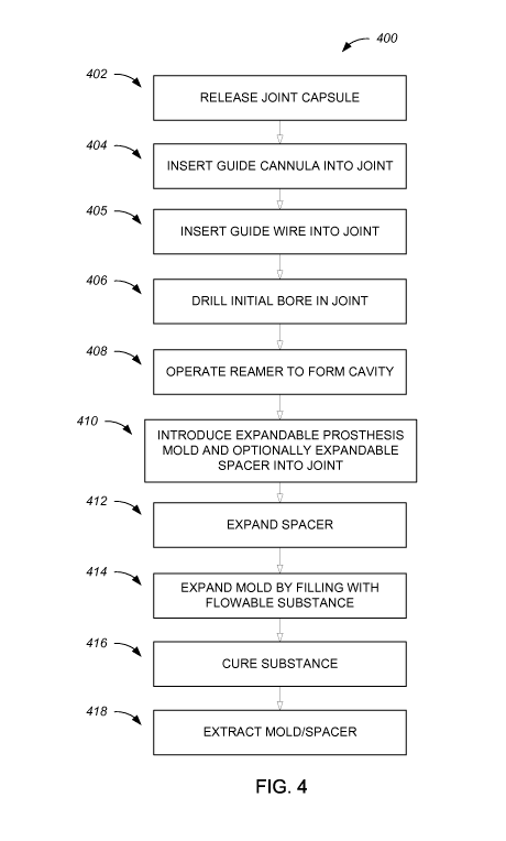
the "procedure"). Intermittent reference is also made to Fig. 4, which shows a
flow chart 400
of the method.
Access to damaged joint 200 during the surgical method may be initialized
through one
or more incisions through the skin and the tissue covering the joint.
Optionally, a small
incision is formed, with a scalpel. Optionally, the incision is straight. The
incision may be
within the range of 4 to 10 millimeteres in size. The incision may be up to 15
mm long or
more. Following incision, one or more working cannulas, as known in the art,
may be
applied, to facilitate straightforward access to the joint through the soft
tissues envelope.
It is to be understood that the one or more incisions are small in comparison
to the
diameter of the prosthesis to be formed, rendering the method minimally-
invasive according
to accepted medical standards.
Optionally, a first incision is made for creating a portal for viewing,
namely, for
insertion of the arthro scope. One or more additional incisions may be formed
to create one or
more working portals for surgical instruments and substances of the method.
Portals may be
swapped during the procedure, if required, such that a viewing portal becomes
a working
portal, and vice versa.
In a step 402 (Fig. 4) of the method, arthroscopic release of a joint capsule
214 of
damaged joint 200 may be performed (not shown in the figures), optionally
using one or
more known techniques such as diathermy, usage of an RF (Radio Frequency)
wand,
CA 02872238 2014-10-30
WO 2013/164830
PCT/1L2013/050376
13
mechanical arthroscopic scissors and/or punches. Optionally, osteophytes are
resected from
the joint surface, on one or both joint surfaces.
Then, in a step 404, a guide cannula, such as guide cannula 328, may be
inserted into
damaged joint 200 through the incision, as Fig. 3A shows.
Reference is now made to Figs. 5A-C, which show guide cannula 328 in more
detail,
from cross-sectional and perspective views. Fig. 5A shows guide cannula 328 in
its collapsed
form, while Figs. 5B-C show it in its expanded form. Guide cannula 328 may
serve to guide
insertion of a central guide wire that will maintain an essentially constant
relative orientation
of various cannulated instruments inserted into damaged joint 200 (Figs. 3A-
B), over the
guide wire, during the procedure. A proximal end 502 of a shank 500 of guide
cannula 328
may include a proximal opening 504 for insertion of the central guide wire,
the channel
extending inside the shank up to a distal end 508 of the guide cannula. Shank
500 may
include a thicker area near proximal end 502, serving as a grip 514.
It is to be understood that the terms 'central guide wire' and 'guide wire',
as used
herein, are interchangeable. These terms refer to a wire, optionally metallic,
over which
instruments, including cannulated instruments, are introduced to the joint at
a desired site.
However, the guide wire may guide non-cannulated tools, using alternative
mechanisms, such
as magnetic attraction. Optionally, the diameter of the guide wire is about 2
millimeters.
At or near its distal end 508, guide cannula 328 may include an expandable
securing
element, such as, for example, arms 510. The securing element serves to secure
distal end
508 to humerus head 202, shown here in perspective, throughout at least part
of the
procedure. Arms 510, shown here only as one example of a securing element, may
each be
arc-shaped, with a radius of curvature matching or close to that of humerus
head 202. Arms
510 may grip and/or circumferentially engage a sphere, an ellipsoid or any
oval shaped
figure. Guide cannula 328 may be provided with arms 510 of different sizes, to
fit different
patients. Optionally, graduation 512 is present on arms 510a-d, such that
their position over
humerus head 202 may be viewed by the surgeon and used for adjusting the
position of the
guide cannula, as necessary. The distance between graduation 512a on arm 510a
and a neck
of humerus head 202 may be used to determine the desired position of the guide
cannula
which in turn assists positioning the guide wire in said desired position.
Further optionally,
arms 510a-d are shaped and positioned such that they define a part of a sphere
or an ellipsoid,
so that shank 500 connects to the arms at a location indented to a central
axis of the sphere or
CA 02872238 2014-10-30
WO 2013/164830
PCT/1L2013/050376
14
the ellipsoid. This may be achieved, for example, by providing two opposing
arms 510a-b
having essentially equal lengths, and two opposing arms 510c-d whose lengths
are different.
Nonetheless, a different securing element (not shown) may be provided, for
securing a
guide cannula to a location other than the humerus head, in case that also a
portion of the
glenoid is to be resected. A distal opening 514 is provided at distal end 508,
facilitating
insertion of the central guide wire to humerus head 202 or a different part of
damaged joint
200.
The securing element, be it arms 510 or a different element, may be introduced
into
damaged joint 200 when collapsed, as Fig. 5A shows, to enable insertion
through a relatively
small incision. When inside the joint, an expansion mechanism (not shown) may
be triggered,
to expand the securing element to its final measurements.
Returning to Figs. 3A-B, guide cannula 328 is optionally placed over the joint
surface
and is used for directing the central guide wire into damaged joint 200 at a
certain, optionally,
predetermined, angle in relation to a neck of humerus head 202, the angle
optionally
matching the indentation of arms 510 in relation to shank 500. The neck is
often referred to as
the part of the humerus head which is situated between its spheroidal
articular surface (shown
more clearly at 102A in Fig. 1) and its elongated deltoid ridge (102B in Fig.
1). A virtual line
surrounding the circumference of the neck is shown at 202C in Fig. 3A. A
central axis of the
neck, which is perpendicular to line 202C, is shown at 202D. An angle 202E
between central
axis 202D and guide cannula 328 is optionally between 0-10, 10-20, 20-30, 30-
40 or 40-50
degrees. For example, angle 202E may be approximately 15 degrees.
Optionally, the choice of angle may assist to reduce the greater tuberosity of
the
humerus relative to the centre of rotation. This effect may improve the
function of the deltoid
muscles and the rotator cuff and may prevent impingement of the greater
tuberosity on the
acromion in elevation of the arm.
Reference is now made to Fig. 3Ba, which shows an exemplary guide wire 328a
following its insertion, through guide cannula 328 of Fig. 3B, into humerus
head 202 of
damaged joint 200. The insertion of guide wire 328a may be performed in a step
405 of the
method (Fig. 4). Guide wire 328a may include a relatively sharp point 328b,
enabling its
penetration into the bone by way of rapid spinning using a suitable spindle.
Sharp point 328h
may be conical, multi-faceted or the like. Optionally, sharp point 328b is
threaded.
In a step 406 (Fig. 4) of the method, a starter drill 322 may be used to drill
an initial
bore, as shown in Fig. 3C, to which reference is now made, along with
reference to Figs. 6A-
CA 02872238 2014-10-30
WO 2013/164830
PCT/1L2013/050376
F, which show starter drill 322 in perspective, side and cross-sectional
views. Starter drill 322
may be used in a cannulated manner, threaded over guide wire 328a into damaged
joint 200.
Starter drill 322 may be a twist-type drill, optionally metallic, having a
diameter of, for
example, about10 millimeters, and optionally ending with a convex surface 602.
Starter drill
5 322 may include a guide channel 604 along its length, enabling it to be
threaded on a guide
wire (not shown). The diameter of a guide channel 604 is within a range that
is appropriate
for enclosing a guide wire 328a.
Optionally, starter drill 322 includes an adjustable stopper, such as stopper
606,
allowing a surgeon to preset a desired drilling depth; upon reaching that
depth, stopper 606
10 comes in contact with one or more of the articular surfaces and prevents
further drilling.
Adjustability of stopper 606 may be enabled, for example, by an adjustment
wheel 608 being
configured, when rotated in one direction, to press onto and secure starter
drill 322 in relation
to the stopper, and, when rotated in the other direction, release the starter
drill and allow its
adjustment. Depth graduation (not shown) may be inscribed and/or printed on
starter drill 322
15 and/or its stopper 606, allowing precise depth adjustment.
Following the drilling of step 406 (Fig. 4), starter drill 322 is removed from
joint 200.
Then, in a step 408, a convex, expandable reamer, such as reamer 330 shown in
Fig. 3D, may
be introduced into and operate on damaged joint 200. Reamer 330 may be
configured to form
the ellipsoidal cavity between the two bones. When first introduced into joint
200, reamer
330 may be in a collapsed form, as shown in Fig, 3D. The diameter of a reamer
330 in a
collapsed form is optionally about 10 millimeter, for a joint in a human
shoulder. Similar or
different diameters may be suitable for the human shoulder joint or different
joints. Upon
reaching a desired location within joint 200, an expansion mechanism may be
triggered, to
expand a tip portion of reamer 330. Upon expansion, the diameter of the reamer
is enlarged,
and may reach a diameter of approximately 36 - 40 millimeters or more for a
human
shoulder, or the same or different diameter for a different joint.
Reference is now made to Figs. 7A-D, which show exemplary reamer 330 in its
collapsed form in more detail, from front, cross-sectional, side and isometric
views,
respectively. Reamer 330 may include an elongated tubular housing 702, having
a diameter
suitable for introduction through the small skin incision.. (Figs. 3C-D). An
internal guide
channel 704 may extend inside housing 702 along its length, enabling its
threading on guide
wire 328a (Fig. 3D).
CA 02872238 2014-10-30
WO 2013/164830
PCT/1L2013/050376
16
A tip portion 706 of reamer 330 may include openings, for example three
openings 708,
enabling the expansion of one or more reaming blades, such as three reaming
blades 710 (in
some of the figures, only two openings and two blades are visible), outside
housing 702. An
alternative reamer (not shown) may include one or more reaming blades which
protrude
forwardly out of a housing, thereby requiring no openings in the housing for
their expansion.
Blades 710 may each be arc-shaped, such that, when expanded, they form a
curved
surface together with a convex distal end 712 which bridges them. Figs. 7E-H
show reamer
330 with blades 710 expanded. The curved surface formed may match the diameter
and/or
shape of the desired ellipsoidal cavity to be formed. One or more of blades
710 may include
diagonal stripes protruding from its external surface, and serving to enhance
shaving of joint
matter, such as bone, cartilage and/or the like.
One or more of blades 710 may be mounted onto two blade arms, a front blade
arm
714a and a rear blade arm 714b. Front blade arms 714a may be connected to
housing using
pivots 716, and rear blade arms 714b may be connected to an expansion
triggering
mechanism using pivots 718. The expansion triggering mechanism enables the
surgeon to
gradually expand blades 710 when the reamer is properly inserted into
position. The
expansion triggering mechanism may be based on, for example, a triggering rod
720
extending from a proximal area of reamer 330 and along at least a portion of
the length of
housing 702. Triggering rod 720 may be contacting, further distally in housing
720, a
triggering cylinder 722, which, in turn, is connected to pivots 718. A
triggering wheel 724
may be threaded around housing 702 at the proximal area. When the surgeon
desires to
expand blades 710, she may turn and thread triggering wheel 724 towards the
distal area of
reamer 330, making the triggering wheel push triggering rod 720, which
triggers cylinder
722, rear blade arms 714b and finally blades 710, causing the latter to
expand.
A motor (not shown) may be used to rotate reamer 330 so as to create the
desired
ellipsoidal cavity. The motor may be started, initially, when reamer 330 is
still in its collapsed
form. Then, while reamer 330 rotates, triggering wheel 724 may be gradually
threaded
towards the distal area of the reamer, thereby gradually expanding the formed
cavity. In Figs.
7E-H, triggering wheel 724 is shown fully threaded in the distal direction,
and blades 710,
accordingly, are fully expanded. Optionally, during at least a portion of the
reaming, a net-
like basket and/or a grater-like reamer may be used, to fine-smooth the
internal surface of the
formed cavity. Fine reaming is intended for obtaining a perfectly smooth
cavity.
CA 02872238 2014-10-30
WO 2013/164830
PCT/1L2013/050376
17
The term "net-like basket" as used herein refers to a perforated sphere,
wherein the
perforation is in the range of micrometers. This sphere is used as a fine
file, and its use results
in a smooth surface (typically, less than 20 microns of average surface
roughness).
In order to form an ellipsoidal cavity, drilling and/or reaming, according to
the above
discussions, may be done at one or more different angles of approach (not
shown), optionally
through one or more additional incisions, such that blades 710 of reamer 330
can reach
essentially the entire inner surface of the desired cavity. For example,
drilling and/or reaming
may be done to resect also part of the glenoid, if the glenoid and/or its
cartilage are also
damaged, so that the resulting cavity extends between the interfacing bones
and within these
bones themselves. Fig. 3E illustrates such an exemplary cavity 332. As a
result of the
reaming, the internal surface of cavity 332 may be exceptionally smooth, so as
to facilitate
smooth joint motion when the patient recovers.
Optionally, an expandable impactor (not shown), similar to reamer 330 but
having an
essentially complete hemispherical and smooth body instead of blades 710, may
be used in
addition to or instead of use of the reamer, to enhance the smoothing of the
internal surface of
cavity 332.
The term "impactor", as used herein, may refer to an instrument which is
capable of
minimizing the average surface roughness. Upon impinging on the cavity's
surface, the
impactor causes mechanic deformation of the cavity's surface, to essentially
the same
geometry of the impactor itself. It compacts the cancellous bone in the
concave internal
surface of the formed cavity.
Optionally, the hemispherical surface of the expandable impactor is of
essentially the
same size and shape as the curved surface created by blades 710 of reamer 330
when
expanded, but is smooth on its convex external surface. Thus, upon expansion,
the
expandable part may be shaped essentially as a hemisphere or a section of a
sphere.
In a step 410 (Fig. 4), once an ellipsoidal cavity of a desired shape, size
and location has
been formed, forming of a joint replacement prosthesis may commence. First,
however, guide
wire 328a (Fig. 3D) may be removed from the joint.
With reference to Fig. 3F, an expandable prosthesis mold, such as mold 334,
may then
be introduced into cavity 332 (Fig. 3E) in a collapsed form. Optionally, mold
334 is an
inflatable mold. Mold 334 may be made of a material being both flexible, so
that it may be
collapsed and expanded, as well as being non-stretchable beyond a certain
final size, so that
the size of the resulting prosthesis may be pre-determined by selection of a
mold of a certain
CA 02872238 2014-10-30
WO 2013/164830
PCT/1L2013/050376
18
final size; this may obviate the need to precisely control inflation pressure
during the
procedure, since the mold will not be able to expand beyond that known size. A
suitable
material may be, for example, PEBAX (Polyether block amide), various Nylon
blends, PET
(Polyethylene terephtalate), Nylon (synthetic polymers known generically as
polyamides)
and/or the like. In addition, mold 334 may exhibit a highly smooth internal
surface, without
stitches, plastic injection marks and/or the like. This may ensure that the
resulting prosthesis
has a perfectly smooth external surface.
Optionally, an insertion instrument, such as insertion instrument 336, may be
used for
the introduction. Reference is now made to Figs. 8A-C, which show cross-
sectional views of
mold 334 and insertion instrument 336 in more detail. Insertion instrument 336
may include
an elongated tubular shaft 802 which is optionally thicker near its proximal
end 804, forming
a grip 806. A working channel 808 may extend internally inside shaft 802. An
input port 810
may be positioned at a proximal end of working channel 808.
Insertion instrument 336 may further include an extendible liner, such as
liner 812,
being a hollow cylindrical instrument mountable around shaft 802, having a
handle 814 and
optionally a storage chamber 816. Before introduction into the joint, mold 334
may be stored
inside storage chamber 816, which protects it during the insertion. Mold 334
may include a
narrow neck (not shown), extending inside shaft 802 optionally up to its
proximal end or even
further, thereby enabling filling of the mold. Alternatively, a separate
inflation tube (not
shown) may extend inside working channel 808 and connect to mold. Mold 334 may
be
positioned inside cavity 332 (Fig. 3F) such that, when the mold is fully
expanded, the mold is
either at the center of cavity or indented from the center.
When mold 334 and storage chamber 816 have been inserted into cavity 332 (Fig.
3F),
handle 814 may be pulled by the surgeon, thereby pulling the entire liner 812
backwards and
exposing the mold.
Optionally, mold 334 is provided inside an expandable spacer (not shown in
this
figure), configured to maintain cavity 332 (Fig. 3F) between the two
interfacing bones at least
during the formation of the prosthesis. The spacer, similar to mold 334, may
have a final size
when expanded, the final size optionally matching that of cavity 332 (Fig.
3F). Upon
expansion of the spacer, it prevents the interfacing bones and/or other parts
of the joint from
collapsing and/or otherwise interfering with the formation of the prosthesis
inside mold 334.
According to other embodiments, mold 334 itself may be configured to expand
such that it
prevents the interfacing bones and/or other parts of the joint from collapsing
and/or otherwise
CA 02872238 2014-10-30
WO 2013/164830
PCT/1L2013/050376
19
interfering with the formation of the prosthesis inside mold 334, thus
obviating the need for a
spacer. Each possibility represents a separate embodiment of the present
invention. Mold 334
may be configured to expand under high pressure, thus maintaining cavity 332
between the
two interfacing bones at least during the formation of the prosthesis and
obviating the use of a
spacer.
Reference is now made to Figs. 9A-B, which show cross-sectional views of mold
334
and an optional spacer 902 containing the mold. Spacer 902 is shown already
expanded,
following its introduction into damaged joint 200 when collapsed over the
collapsed mold
334, the two constituting, essentially, a double-lumen expandable apparatus.
Optionally, the
joint introduction of the two is performed using an insertion instrument, such
as insertion
instrument 336 of Figs. 8A-C.
Fig. 9A shows mold 334 in its collapsed form inside the expanded spacer 902.
For
simplicity of presentation, necks of mold 334 and spacer 902 are shown
schematically,
without reference to an insertion instrument, pumping system and/or the like.
In a step 412
(Fig. 4), spacer 902 is expanded. Optionally, the expansion is by pumping air
or fluid into a
filling neck 904 of spacer 902, while keeping an emptying neck 906 of the
spacer closed. It is
to be noted that a spacer according to the present invention may have the
shape of spacer 902
or other shapes, such as forceps, expandable arms and the like, so as long as
the spacer is
configured to maintain the cavity between the two interfacing bones at least
during the
formation of the prosthesis.
Then, in a step 414 (Fig. 4), mold 334 is expanded, by filling it with a
flowable, curable
substance, through its filling neck 910, to form a prosthesis 908 inside it.
Optionally, solids
(not shown) may be intermixed with the substance, for purposes such as
reducing the weight
of prosthesis 908, structurally enforcing the prosthesis and/or the like. For
example, hollow
globules may be intermixed with the substance.
A final size of mold 334 may be such that a gap is maintained between the
outer surface
of the mold and the inner surface of spacer 902. For example, the diameter of
mold 334 may
be a few millimeters to about 1 centimeter smaller than that of spacer 902,
leaving a gap of a
few millimeters, for example, 5 millimeters between the two. A priming step
may be
performed at the beginning of the filling. While filling the prosthesis mold,
the pressure in the
outer spacer is preserved. This may be achieved by allowing escape of the
fluid or air through
the output neck.
CA 02872238 2014-10-30
WO 2013/164830
PCT/1L2013/050376
In a step 416 (Fig. 4), following the filling of mold 334, curing of the
substance may
take place, for example using an ultraviolet (UV) illuminator (not shown),
introduced
arthroscopically. Alternatively, if an Epoxy is used, curing will occur
without external
intervention. Suitable materials include, for example, EPO-TEK UVO ¨ 114 (UV
curable,
5 command
cure), EPO-TEK 715 and/or Stryker medical's Simplex P SpeedSet among others.
The curing process may be exothermic. If so, an arthroscopic fluid, such as
saline, may be
used to flush the surroundings of mold 334 during the curing, so that no
tissue is substantially
affected by the heat. Following the curing, prosthesis 908 is rigid,
ellipsoidal and smooth.
Optionally, prosthesis 908 may be enlarged by forming one or more additional
10
prosthetic layers over it. This may be performed, for example, by providing
multiple
expandable molds of gradual sizes one inside the other, and filling and curing
them
sequentially. If this option is employed, a spacer may or may not be used. One
or more of the
expandable molds may be isomorphic and/or axisymmetrical at least after a
prosthesis and/or
a prosthetic layer(s) has been formed inside them. Alternatively, one or more
of the
15
expandable molds may not be isomorphic and/or axisymmetrical. In some
alternatives,
axisymmetricality of the prosthesis and/or a prosthetic layer(s) is of less
importance, since
when a layer covers its predecessor, the lack of axisymmetricality is not
exhibited.
Reference is now made to Fig. 10, which shows, in perspective, an example of
three
molds of gradual sizes provided one inside the other. An internal mold 1002 is
filled first,
20 through
its neck or inflation tube 1002A, to form a first prosthesis. It is then
cured. Next, an
intermediate mold 1004 is filled, through its neck or inflation tube 1004A, to
form a
prosthetic layer over the previous prosthesis. Curing follows the filling.
Finally, an external
mold 1006 is filled, through its neck or inflation tube 1006A, to form and
cure another
prosthetic layer over the previous prosthetic layer.
Optional advantages of forming a large prosthesis gradually, rather than
creating a large
prosthesis at once using one mold, include, for example, reduced curing time,
lower
temperature (if curing is an exothermic reaction), better-controlled
hardening, higher
confidence, reduced bubble formation and/or reduced imperfections. The reduced
curing time
leads to improved curing, since less material is involved in each curing step
and less
outgassing is caused. Incremental buildup of the implant increases strength
for compression
and eliminates stress cracking, micro cracks and other material imperfections.
When multiple molds are used to form a prosthesis and a prosthetic layer(s)
sequentially, one or more of the molds may not be removed from the joint prior
to forming
CA 02872238 2014-10-30
WO 2013/164830
PCT/1L2013/050376
21
the next prosthetic layer over them. If a mold is to remain in place, it may
be manufactured of
a material or a combination of materials suitable for staying inside the cured
substance
permanently. One example of such a material is THY (Terpolymer of
Tetrafluoroethylene,
Hexafluoropropylene and Vinylidene fluoride). THY is an extremely flexible
fluoropolymer,
having excellent optical clarity. Combined with the traditional chemical and
environmental
resistance of fluoropolymers, THY may be a suitable material for forming one
or more of the
molds. THY provides, for example, excellent permeation, good UV transmittance
and more.
Either if a single mold or multiple molds are used, it may be desired to
extract one or
more of them following the curing, and optionally also the spacer. In a step
418 (Fig. 4),
extraction of a mold or a spacer may be performed.
One or more instruments may be used for extraction, such as the instruments
shown in
Figs. 11-15. A first example is shown in Fig. 11, to which reference is now
made. An
extraction instrument 1100 may include a handle 1102, to which an elongated,
flexible arm
1104 is connected. Arm 1104 may be curved towards it end, so that it may be
wrapped
around the ellipsoidal mold once inside the joint. Arm 1104 may terminate with
a blade 1106.
To extract a mold or a spacer, arm 1104 is arthroscopically introduced into
the joint, such that
its curved area wraps around at least a portion of the mold or spacer. Blade
1106 may then
contact the mold or spacer. When extraction instrument 1100 is pulled, blade
1106 may drag
on the surface of the mold or the spacer, forming an elongated cut, whether to
the full
thickness of the mold/spacer or a part of it. Then, the torn mold or spacer
may be pulled out
of the joint through their necks or inflation tubes.
A second example of an extraction instrument is shown in Fig. 12. This
extraction
instrument may include an elongated, flexible strip 1200 threaded through an
arthroscopic
instrument, such as insertion instrument 336 of Figs. 8A-C, while mold 334 is
still held by
the insertion instrument. As strip 1200 progresses inside shaft 802, it
reaches mold 334 and
contacts its outer surface. Further pushing of strip 1200 causes it to
progress on the outer
surface of mold 334, until it reaches desired position 1202. Pulling strip
1200, for example
using handle 1204, enables ripping and/or pulling of mold 334. Each
possibility represents a
separate embodiment of the present invention.
Figs. 13A-D show a third example of an extraction instrument 1300 for mold 334
connected to neck 910a. A thin, triangular polymeric film 1302 may be affixed,
using an
adhesive, to the outer surface of the mold or spacer. Then, a flexible
polymeric strip 1304 is
introduced into the joint and adhered, at its edge, to film 1302. Strip 1300
is optionally
CA 02872238 2014-10-30
WO 2013/164830
PCT/1L2013/050376
22
inserted into the joint similar to the insertion of strip 1200 of Fig. 12.
When strip 1304 is
pulled, concentrated shear forces are created on the outer surface of the
mold, at the point
where one of film's 1302 sharp corners is located. If the mold is made of a
polymer, these
forces may cause plastic deformation of the mold, finally leading to its
rupture. Then, while
strip 1304 continues to be pulled, an elongated crack is formed in mold, such
that it may be
easily extracted by pulling out through its neck or inflation tube.
According to other examples, the mold and/or spacer may be extracted by
providing
them with one or more wires, at least partly attached to or embedded in their
ellipsoidal
surface and extending to their necks/inflation tubes. To extract them, the
wires may be pulled,
causing the tearing of the mold or spacer along the path of the wires and the
pulling of the
torn parts outside. Figs. 14 and 15 depict exemplary extracting instruments
using such wires.
A fourth example of an extraction instrument is shown in Figs. 14A-E, showing
mold
334', situated between glenoid cavity 106 and humerus head 202, following
filling of mold
334' and formation of prosthesis 908. According to the example shown in Figs.
14A-E, mold
334' comprises wires 1400a-c attached to or embedded within the surface of
mold 334'. Each
possibility represents a separate embodiment of the present invention. Wires
1400a-c extend
on or within the surface of mold 334', from the apex of mold 334' situated
opposite the
opening of neck 910 and in the direction of neck 910, possibly threading
through shaft 802 of
an arthroscopic instrument such as insertion instrument 336 of Figs. 8A-C.
According to
some embodiments, the surface of a mold may comprise two or more wires,
embedded in or
attached to the surface, the wires roughly dividing the surface to at least 2
slices. Each
possibility represents a separate embodiment of the present invention. Wires
1400a-c are
attached to or embedded in the surface of mold 334' such that they roughly
divide its surface
to slices 1402a-d. Each possibility represents a separate embodiment of the
present invention.
According to some embodiments, slices 1402a-d may be of the same or different
sizes.
According to some embodiments, wires 1400a-c do not extend through the entire
length of
mold 334"s surface up to the connection point of neck 910 with mold 334' but
protrude from
the surface before reaching the connection point, thus allowing the proximal
part of mold
334' to remain intact following pulling of wires 1400a-c. As used herein, the
term "proximal"
refers to the side closer to the care giver using the surgical kit and/or mold
of the invention.
Pulling of the proximal part of wires 1400a-c is configured to induce ripping
of the
surface of mold 334' along the path of wires 1400a-c. It is to be noted that
ripping of mold
334' by each wire of wires 1400a-c may be such that ripping occurs only at a
single point at a
CA 02872238 2014-10-30
WO 2013/164830
PCT/1L2013/050376
23
time and not along the entire wire simultaneously. Ripping of mold 334' at a
single point at a
time may require a lower ripping force, thus facilitating easier and/or faster
ripping. Wires
1400a-c may be pulled through an arthroscopic instrument such as insertion
instrument 336
of Figs. 8A-C. Fig. 14A depicts mold 334' prior to pulling of wires 1400a-c.
Fig. 14B depicts
mold 334' once pulling of wires 1400a-c has started, thus ripping of the
surface of mold 334'
begins at the apex of mold 334' situated opposite the opening of neck 910.
Figs. 14C-D
depict mold 334' as the ripping of its surface continues with further pulling
of wires 1400a-c,
thus slices 1402a-d detach from prosthesis 908. Fig. 4E shows mold 334' as it
fully detached
from prosthesis 908 following ripping of the mold's surface by wires 1400a-c.
Following
detachment of mold 334' from prosthesis 908, mold 334' is extracted from the
subject,
possibly through an arthroscopic instrument such as insertion instrument 336
of Figs. 8A-C.
Mold 334' may be extracted by pulling on the proximal part of wires 1400a-c
and/or by
pulling neck 910 and/or by pulling a string directly connected to mold 334'
(not shown).
Each possibility represents a separate embodiment of the present invention.
Wires 1400a-c or 1500, as depicted in Figs. 14 and 15 may be rigid and/or
strong
enough to enable pulling them in order to rip and extract mold 334' or 334",
respectively, but
thin enough so that they do not cause bumping or blistering in the surface of
mold 334' or
334", respectively, in a way that may affect the smoothness of prosthesis 908.
Wires 1400a-c
or 1500, as depicted in Figs. 14 and 15 may be at least partly integrally
formed with mold
334' or 334", respectively. Wires at least partly integrally formed with a
mold, according to
the present invention, may differ from the mold by properties such as, but not
limited to,
strength, rigidity, thickness, electric conductivity and the like.
According to some embodiments, mold 334' is weakened prior to and/or during
pulling
of wires 1400a-c. Each possibility represents a separate embodiment of the
present invention.
Weakening of mold 334' may be through exposure of mold 334' to energy such as,
but not
limited to, heat energy, electrical energy, light energy, radio frequency,
ultrasonic energy and
the like, or any combination thereof. Each possibility represents a separate
embodiment of the
present invention. Exposure of mold 334' to energy may induce heating and/or
change in
physical properties of mold 334', thus leading to its weakening. Each
possibility represents a
separate embodiment of the present invention. Weakening of mold 334' may
facilitate easier
and/or faster ripping of mold 334' by wires 1400a-c, ultimately facilitating
easier extraction
of mold 334' from the subject's body. According to some embodiments, weakening
the
surface of mold 334' by electricity and the like may enable using wires 1400a-
c that are
CA 02872238 2014-10-30
WO 2013/164830
PCT/1L2013/050376
24
thinner and/or less rigid than wires used without weakening mold 334'. Each
possibility
represents a separate embodiment of the present invention.
Exposure of mold 334' to energy may be through the use of an energy source
external
to the subject's body, such as, but not limited to, an ultrasonic transducer,
a radio frequency
emitter and the like. An energy source external to the subject's body may
transmit energy
such as, but not limited to, ultrasonic energy or radio frequency to mold
334'. The external
energy source may not have to be physically engaged with mold 334' in order to
transfer
energy to the mold.
Alternatively, an energy source, such as, but not limited to, an electricity
source, may
physically engage with mold 334' through wires, such as, but not limited to,
wires 1400a-c.
Accordingly, wires 1400a-c may optionally be made of a material such as, but
not limited to,
a metal, configured to transmit energy such as electricity. The proximal side
of wires 1400a-c
may optionally be connected to an external energy source, such as but not
limited to, an
electricity source. Alternatively, wires 1400a-c may be connected to an energy
source which
is inserted into the subject's body, possibly situated on an insertion
instrument such as
insertion instrument 336 of Figs. 8A-C. The energy source may transfer energy,
such as an
electric current, through wires 1400a-c, thus heating the surface of mold
334'. The heating of
the surface of mold 334' may weaken the surface. According to some
embodiments, at least
two wires, such as wires 1400a-c, extending from mold 334', are connected to
an electricity
source external to a the subject's body, such that wires 1400a-c and the
electricity source
form a closed electrical circuit. Alternatively, mold 334' may be formed of an
electricity
conducting material such that wires 1400a-c, mold 334' and the external
electricity source
form a closed electrical circuit. The electrical source may possibly be
inserted into the
subject's body and form a closed electrical circuit with wires 1400a-c and
possibly with mold
334'. An electrical source inserted into the subject's body may be situated on
an insertion
instrument such as insertion instrument 336 of Figs. 8A-C or possibly situated
on mold 334'
itself or on a spacer surrounding mold 334' (not shown).
A fifth example of an extraction instrument is shown in Figs. 15A-E, showing
mold
334", situated between glenoid cavity 106 and humerus head 202, following
filling of mold
334" and formation of prosthesis 908. According to the example shown in Figs.
15A-E, mold
334" comprises a single wire 1500 attached to or embedded within the surface
of mold 334".
Each possibility represents a separate embodiment of the present invention.
Wire 1500
follows a spiral course on or within the surface of mold 334", starting at the
apex of mold
CA 02872238 2014-10-30
WO 2013/164830
PCT/1L2013/050376
334" situated opposite the opening of neck 910 and extending towards neck 910.
The
proximal part of wire 1500 extends towards neck 910 and may extend through an
arthroscopic instrument such as insertion instrument 336 of Figs. 8A-C.
Pulling on the
proximal part of wire 1500 is configured to result in spiral ripping of the
surface of mold
5 334"
along the path of wire 1500, thus exposing prosthesis 908, as can be seen for
example
in Figs. 15C-D. It is to be noted that ripping of mold 334" by wire 1500 may
be at a single
point at a time and not along the entire length of wire 1500 simultaneously,
thus possibly
requiring a lower ripping force. A lower ripping force may enable faster
and/or easier ripping
of mold 334". The ripping of mold 334" by wire 1500 may start at the apex of
mold 334"
10 situated
opposite the opening of neck 910 and advance in the direction of neck 910, or,
alternatively, start at a side of mold 334" closer to neck 910 and advance in
the opposite
direction from neck 910 with pulling of wire 1500. Pulling on the proximal
part of wire 1500
and/or pulling neck 910 and/or pulling a string directly connected to mold
334" (not shown)
results in extraction of mold 334" from the subject's body, as can be seen in
Fig. 15E.
15 As
described for wires 1400a-c, wire 1500 may be made of a material configured to
transmit energy to mold 334". Similarly to mold 334', mold 334", may be
weakened prior to
and/or during pulling of wire 1500 through transmission of energy to mold
334", such as, but
not limited to, electrical energy and/or sound energy. The energy may be
transmitted to mold
334" through wire 1500 which is connected to an energy source external or
internal to the
20 subject's
body. Alternatively, the energy source may transfer energy to mold 334"
without
being physically connected to mold 334".
Following the curing of the material inside the mold, a protrusion of cured
substance
may still remain in the area of the mold's neck or inflation tube (also its
"input port").
Reference is now made to Fig. 8C, which shows the area where the protrusion
334A is
25 formed.
In an optional step of the method, a file, a cutter and/or the like may be
used to
remove the protrusion, so as to leave the mold completely smooth near its
input port.
As an alternative to the in-situ formation of a joint replacement prosthesis
such as
prosthesis 908, using an expandable mold, such as mold 334, a different joint
replacement
prosthesis may be assembled inside the joint in a minimally-invasive manner. A
joint
replacement prosthesis assembly may be comprised of a plurality of parts, each
having a
small enough size which enables its introduction into a damaged joint in a
minimally-
invasive manner. The term "size" may refer to a measurement of the largest
dimension of
such part, which measurement dictates the size of an incision to made in the
patient's skin
CA 02872238 2014-10-30
WO 2013/164830
PCT/1L2013/050376
26
and the size (for example diameter) of joint tissue which needs to be cleared
away en route
the site where the prosthesis is to be assembled. The parts may be introduced
into the site
individually, and assembled inside the site to form an ellipsoidal joint
replacement prosthesis,
which may have a smooth outer surface.
Reference is now made to Fig. 16, which shows an exemplary joint replacement
prosthesis assembly (herein after "prosthesis assembly") 1600 in a cross-
sectional view, as
well as the individual parts forming the prosthesis assembly.
Generally, prosthesis assembly 1600 may be assembled from a core structure
(hereinafter "core") 1602, having mounted thereon multiple slices, such as
slices 1604,
together forming the desired ellipsoidal shape ¨ in this example a sphere. Six
slices 1604 are
shown in this figure, but any number of slices which is two or above is
intended herein. The
geometry of each of slices 1604 may include a bottom structure enabling its
attachment to
core 1602, and optionally a side structure enabling the slices to be attached
to one another.
Option A for slices 1604a includes only a bottom structure, while Option B for
slices 1604b
includes both a bottom structure and a side structure.
Prosthesis assembly 1600 may be introduced into and assembled inside the
formed joint
cavity as follows: Core 1602 and each of slices 1604 may be inserted into the
cavity
individually, such that only a relatively small incision and pathway are
needed, similar to the
rationale of mold 334 forming prosthesis 908 (Figs. 9A-B). This facilitates
the minimally-
invasive nature of the procedure. Slices 1604 are then being slid onto core
1602, such that the
bottom structures of the slices mount onto matching structures in the core.
When all slices
1602 are mounted on core 1602, a securing bolt 1608 may be inserted into a
central threaded
bore of the core, and fastened using an opposite bolt 1610. This finally locks
slices 1602 and
core 1602 together, serving as a locking mechanism. Optionally, one or both of
bolts 1608
and 1610 are hex-socket (also Allen) bolts. Bolts 1608 and 1610 may each have
a cap being
sufficiently large so that it covers at least the area where the bottom
structures of slices 1604
and the matching structures in core 1602 meet. This way, the caps keep slices
1604 from
sliding off core 1602. A bit, such as bit 1612, may be used to seal each hex
socket, such that
prosthesis assembly 1600, as a whole, has the smoothest possible external
surface.
As an alternative to having securing bolt 1610 and core 1602 as separate
pieces, they
may be combined in a single core body (not shown). This core body will have
one end with a
rim preventing the slices from sliding off at that end, and a bore at the
other end in which a
CA 02872238 2014-10-30
WO 2013/164830
PCT/1L2013/050376
27
bolt with a large enough cap may be threaded, in order to prevent the slices
from sliding off
at that side.
In addition or as an alternative to having bolts with caps sized as discussed
above, a
different locking mechanism may be included in a prosthesis assembly. For
example, its core,
slices and/or bolt(s) may be formed such that threading of at least one of the
bolts causes the
matching structures of the core and slices to deform and prevent free
movement.
As apparent from the above discussions, a surgical kit according to the
present
disclosure may include at least some of the following, and optionally a
plurality of each: an
expandable prosthesis mold configured to be arthroscopically introduced into a
joint; an
arthroscopic instrument configured to form an ellipsoidal cavity between two
interfacing
bones of the joint, for receiving the mold; a flowable, curable substance
configured for
forming the prosthesis inside the mold; an expandable spacer configured when
expanded, to
maintain the ellipsoidal cavity between the two interfacing bones; an
impactor; a pumping
system; an arthroscopic extraction instrument; a starter drill configured to
drill an initial hole
in the joint; a guide cannula configured to be secured relative to the joint
and to guide said
starter drill into the joint at a predetermined angle and to position the
guide wire; a guide
wire; a file or a cutter; and a UV curer. If the prosthesis assembly is used,
its core, slices and
optionally one or more other required parts may be included in the kit.
Optionally, one or
more suitable screwdrivers and/or hex (Allen) keys may be provided as well.
Various versions and alternatives for element of the kit have been discussed
above.
Further one or more elements may be included in the kit, as apparent from the
above
discussions.
In the description and claims of the application, each of the words "comprise"
"include"
and "have", and forms thereof, are not necessarily limited to members in a
list with which the
words may be associated. In addition, where there are inconsistencies between
this
application and any document incorporated by reference, it is hereby intended
that the present
application controls.