Note: Descriptions are shown in the official language in which they were submitted.
CA 02873224 2014-11-10
WO 2013/152341
PCT/US2013/035536
ADVANCED METHODS, TECHNIQUES, DEVICES, AND SYSTEMS
FOR CRUCIATE RETAINING KNEE IMPLANTS
RELATED APPLICATIONS
[0001] This application claims the benefit of U.S. Ser. No. 61/621,333,
entitled
"Advanced Methods, Techniques, Devices and Systems for Cruciate Retaining Knee
Implants," filed April 6, 2012, and of U.S. Ser. No. 61/ 798,537, entitled
"Advanced
Methods, Techniques, Devices and Systems for Cruciate Retaining Knee
Implants," filed
March 15, 2013, the disclosure of each of which is hereby incorporated by
reference herein in
its entirety.
TECHNICAL FIELD
[0002] The disclosure relates to improved and/or patient adapted (e.g.,
patient-specific
and/or patient-engineered) orthopedic implants, as well as related methods,
designs, systems
and models. More specifically, disclosed herein are improved methods, designs
and/or
systems for joint implant components that facilitate retention and/or repair
of connective
and/or soft tissues during a joint replacement procedure.
BACKGROUND
[0003] When a patient's knee is severely damaged, such as by
osteoarthritis, rheumatoid
arthritis, or post-traumatic arthritis, it may be desirous to repair and/or
replace portions or the
entirety of the knee with a total or partial knee replacement implant. Knee
replacement
surgery, also known as knee arthroplasty, can help relieve pain and restore
function in injured
and/or severely diseased knee joints, and is a well-tolerated and highly
successful procedure.
Where a total joint replacement is needed, it is often performed by a surgeon
via an open
procedure.
[0004] In an open procedure, the surgeon typically begins by making an
incision through
the various skin, fascia, and muscle layers to expose the knee joint and
laterally dislocating
the patella. The anterior cruciate ligament is often excised (if not already
damaged or
severed), and the surgeon will selectively sever or leave intact the posterior
cruciate ligament
¨ depending on the surgeon's preference and the condition of the PCL. Next,
various surgical
techniques are used to ablate, remove, shape or otherwise prepare the
arthritic joint surfaces,
SUBSTITUTE SHEET (RULE 26)
SUBSTITUTE SHEET (RULE 26)
CA 02873224 2014-11-10
WO 2013/152341
PCT/US2013/035536
and the tibia and femur are exposed for preparation and resection to accept
various implant
components.
[0005] Once the underlying bony anatomical support structures have been
prepared, both
the tibia and femur will typically receive an artificial joint component made
of metal alloys,
high-grade plastics and/or polymers to replace native anatomy and desirably
function as a
new knee joint. In the case of tibial implant components, the artificial joint
can include a
metal receiver tray that is firmly fixed to the tibia. In many cases, the
tibial implant further
includes a medical grade plastic insert (i.e. it may also be known as a
"spacer") that can be
attached to the tray and positioned between the femoral component(s) and the
tibial tray to
create a smooth gliding surface for articulation of the components. Such a
system can also
allow for inserts of multiple sizes and/or thicknesses, which facilitates in-
situ balancing of the
knee as well as allowing the placement of inserts of differing designs and/or
shapes.
[0006] Various surgical procedures in the past have sought to retain
connective knee
tissues during joint repair and/or replacement, but such techniques and
associated implant
designs have not gained widespread clinical acceptance for a variety of
reasons. See, for
example, U.S. Patent Serial Number 4,207,627 to Cloutier, entitled "Knee
Prosthesis" filed
June 17, 1980, and J.M. Cloutier, Results of Total Knee Arthroplasty With A
Non-Constrained
Prosthesis, 65 J. BONE JOINT SURG. Am. 906 (1983); J.M. Cloutier et al., Total
Knee
Arthroplasty with Retention of Both Cruciate Ligaments: A Nine to Eleven-Year
Follow-Up
Study, 81-A J. BONE JOINT SURG. Am. 697 (May 1999).
[0007] While the implantation of total knee implant components via open
procedures
is a well accepted procedure that is well tolerated by patients and has a high
success rate,
surgeons often prefer to minimize the disruption and/or removal of hard and
soft tissues
except where absolutely necessary. For example, the use of minimally-invasive
and/or less-
invasive surgical procedures has become increasingly prevalent, as such
procedures are often
associated with faster patient healing times and less scarification of the
patient's anatomy.
Moreover, where portions of a patient's existing anatomy, such as an ACL or
PCL, are
substantially intact and/or functional in the damaged knee, many surgeons
would prefer to
maintain the integrity of these structures during the surgical implantation
procedure, as such
structures can greatly contribute to the ultimate stability and/or performance
of the treated
anatomy. Unfortunately, many current implant designs require the removal of
such
SUBSTITUTE SHEET (RULE 26)
SUBSTITUTE SHEET (RULE 26)
CA 02873224 2014-11-10
WO 2013/152341
PCT/US2013/035536
structures, even where such structures are fully functional, in order to
accommodate the
implant components.
[0008] Accordingly, there is a need in the art for patient-specific and/or
patient-
adapted joint replacement implant components and associated procedures that
facilitate the
retention and/or repair of anatomical structures such as the ACP and/or PCL
(and/or other
relevant hard and/or soft tissue structures) during surgical procedures. In
addition, there is a
need in the art for such implants and/or procedures that can be implanted via
less-invasive
and/or minimally-invasive procedures.
SUMMARY
[0009] Various embodiments described herein include implant components
suitable
for use in a patient's knee, including multi-component systems incorporating
one or more
tibial trays, inserts, tools, methods, techniques and various devices that
facilitate the
preservation and/or repair of the ACL and PCL of a patient. Preservation of
the ACL and/or
PCL of a patient may improve physiological function and/or motion of the knee.
Various
other embodiments enable the retention of anatomical structures that can
facilitate the surgical
repair of various hard and/or soft tissues, including connective tissues such
as the ACL and/or
PCL of a patient.
[00010] In various embodiments, the implant components can include features
such as
cutout sections, notches or "windows" for accommodating various portions of
the patient's
natural anatomy, including bony anatomical structures and/or soft tissue
structures.
Optionally, these windows can facilitate the insertion, positioning and/or
anchoring of the
prosthesis to the underlying anatomical structures. In addition, various
embodiments of tools
and procedures described herein facilitate the preparation of the patient's
anatomical
structures for the implant components.
[00011] Disclosed herein are various advanced methods, devices, systems for
implants,
tools and techniques that facilitate the surgical repair of a knee joint while
allowing retention
of the natural central ligaments of the knee (and/or other related
structures), thereby desirably
preserving controlled rotation and translation of the repaired joint. In many
embodiments, the
procedures can provide adequate pain relief, preserve normal axial alignment
of the limb, and
preserve stability ¨ this, in turn, will desirably reduce shear stresses at
the component-cement-
bone interfaces.
3
SUBSTITUTE SHEET (RULE 26)
SUBSTITUTE SHEET (RULE 26)
CA 02873224 2014-11-10
WO 2013/152341
PCT/US2013/035536
[00012] The embodiments described herein may be successfully applied to
other
damaged or diseased articulating joints where a surgeon desires to preserve
natural ligaments
and/or other underlying anatomical structures, including in the shoulder
and/or hip. Also,
various embodiments described herein can be successfully applied to total
knee,
bicompartmental or unicompartmental knee surgery.
[00013] Various embodiments described herein include systems having
ligament
retaining components and techniques, including: (1) tibial component systems;
(2) improved
femoral components; (3) surgical jigs/guides/tools; and (4) surgical
methods/techniques.
BRIEF DESCRIPTION OF THE DRAWINGS
[00014] The foregoing and other objects, aspects, features, and advantages
of
embodiments will become more apparent and may be better understood by
referring to the
following description, taken in conjunction with the accompanying drawings, in
which:
[00015] FIG. 1 depicts a perspective view of a knee joint, showing
associated hard
tissue structures and soft connective tissues;
[00016] FIG. 2 depicts a frontal view of the femur and tibia bones of the
knee joint of
FIG. 1;
[00017] FIG. 3 depicts a frontal view of a tibia including a set of
exemplary resection
surfaces;
[00018] Fig. 4 depicts a perspective view of the tibia of FIG. 3, with a
series of
exemplary resections performed on the tibia and a retained central region;
[00019] FIG. 5 depicts a top plan view of one embodiment of a tibial
implant
component with an outer periphery depicted in dotted lines;
[00020] FIG. 6 depicts a top plan view of an alternate embodiment of a
tibial implant
component with an outer periphery depicted in dotted lines;
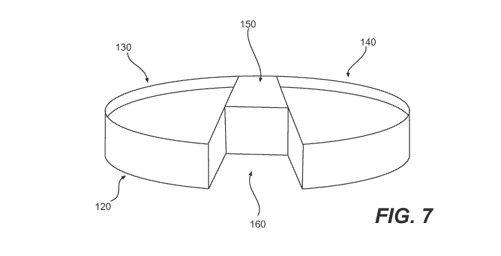
[00021] FIG. 7 depicts a perspective schematic view of one exemplary design
for an
embodiment of a tibial tray;
[00022] Fig. 8 depicts an alternative embodiment of a tibial tray for use
with a PCL
retaining implant system;
4
SUBSTITUTE SHEET (RULE 26)
SUBSTITUTE SHEET (RULE 26)
CA 02873224 2014-11-10
WO 2013/152341
PCT/US2013/035536
[00023] FIG. 9 depicts an alternative embodiment of a set of tibial tray
components
that have been selected and/or designed to accommodate the unique placement of
a patient's
PCL;
[00024] FIG. 10 depicts a top plan view of an unresected tibial surface,
with an
exemplary less-invasive and/or minimally-invasive surgical access window
through the skin
and overlying tissues;
[00025] FIG. 11 depicts a top plan view of one embodiment of a resected
tibial surface,
with various areas that may be difficult for a surgeon to access and/or
visualize highlighted;
[00026] FIGs. 12 and 13 depict top plan and side perspective views of an
alternate
embodiment of a resected tibial surface including a central region having one
or more canted
or angled walls;
[00027] FIG. 14 depicts a schematic side view of a knee joint with a femur
and tibia
connected together via the ACL and PCL;
[00028] FIG. 15 depicts a schematic side view of the knee joint of FIG. 14,
with the
ACL severed or otherwise released and the tibia advanced relative to the femur
for improved
surgical access;
[00029] FIGS. 16 and 17 depict front and side views of one embodiment of a
tibial
guide tool or jig for preparing a tibia to receive a ligament sparing tibial
tray;
[00030] FIG. 18 depicts the tibia of FIGs. 16 and 17 after removal of the
jig, with three
drill channels formed therein;
[00031] FIG. 19A depicts the tibia of FIG. 18, with various combinations of
additional
surgical steps performed to remove various sections of the tibial surface in
preparation for the
tibial tray implant;
[00032] FIG. 19B depicts a frontal perspective view of the tibia of FIG.
19A, with
portions of the drill channels forming sections of the prepared tibial
surface;
[00033] FIGs. 19C and 19D depict front plan views of a drill channel and
exemplary
cut planes;
[00034] FIG. 20 depicts a top plan view of one embodiment of a tibial tray
for use in
an ACL/PCL retention procedure;
SUBSTITUTE SHEET (RULE 26)
SUBSTITUTE SHEET (RULE 26)
CA 02873224 2014-11-10
WO 2013/152341
PCT/US2013/035536
[00035] FIG. 21 depicts a top plan view of an alternate embodiment of a
tibial tray,
including a pair of attachment or locking mechanisms for securing one or more
inserts to the
tray;
[00036] FIG. 22 depicts a diagram of a tibial surface prepared in
accordance with
various embodiments described herein;
[00037] FIG. 23 depicts a top plan view of an alternate embodiment of a
tibial tray
design that incorporates a notched section to accommodates a remaining natural
section of the
tibial surface;
[00038] FIG. 24 depicts a top plan view of alternative designs for a tibial
tray,
including exemplary medial and lateral articulating surfaces;
[00039] FIG. 25 depicts an alternate embodiment of a tibial tray design,
including
various rounded or curved surfaces;
[00040] FIG. 26 depicts an alternate embodiment of a tibial tray design,
including one
or more flattened and/or angled surfaces;
[00041] FIGs. 27 and 28 depict top plan and side views of an alternative
embodiment
of a surgical cut or guide tool for use in preparing portions of the surface
of the tibial bone;
[00042] FIG. 29 depicts a side plan view of an alternate embodiment of a
tibial guide
tool or jig for use in preparing the surface of a tibia;
[00043] FIG. 30 depicts a side plan view of another alternate embodiment of
a tibial
guide tool or jig for use in preparing the surface of a tibia;
[00044] FIG. 31 depicts an alternate embodiment of a jig having external
indicia that
substantially matches or indicates one or more features of the targeted
anatomy and/or
features of interest for the surgeon's reference;
[00045] FIGs. 32 and 33 depict a set of jigs for use in creating a
plurality of cut planes
and/or other surgical objectives;
[00046] FIG. 34 depicts a side plan view of an alternate embodiment of a
tibial guide
tool or jig for use in preparing the surface of a tibia;
[00047] FIGs. 35 and 36 depict exemplary surgical cutting instruments;
6
SUBSTITUTE SHEET (RULE 26)
SUBSTITUTE SHEET (RULE 26)
CA 02873224 2014-11-10
WO 2013/152341
PCT/US2013/035536
[00048] FIG. 37 shows an image of a bi-cruciate retaining patient-adapted
knee
replacement implant system including a patient-specific femoral component and
a patient-
specific cruciate-retaining tibial tray component;
[00049] FIGs. 38A through 38C depict three different types of step cuts
separating
medial and lateral resection cut facets on a patient's proximal tibia;
[00050] FIGs. 39A through 39D depict side views of a tibial plateau in an
uncut
condition and implanted with various combinations of lower metal backed tibial
tray
components and upper inserts;
[00051] FIGS. 40A through 40E show side views of exemplary combinations of
tibial
tray and insert designs;
[00052] FIG. 41 is a flow chart for adapting a blank implant component for
a particular
patient;
[00053] FIG. 42 shows an example of a femoral component design for a bi-
cruciate
retaining knee implant system as described herein.
[00054] Tibial Component Systems
[00055] Tibial component systems embodiments described herein facilitate
the design
of "patient-specific," "patient-engineered" and/or "standard off-the-shelf"
tibial trays and
tibial inserts (and various combinations thereof) that preserve one or both
natural central
ligaments of the knee (including the ACL and PCL). Such systems can
significantly reduce
the potential for migration, instability, and preserve the normal flexion,
extension, and
rotation of the knee.
[00056] In various embodiments, the size of the ligament preserving tibial
tray may be
designed as patient-specific or patient-engineered by incorporating patient-
specific and/or
patient-engineered measurements into the outer perimeter of the tibial
component. The
patient image data (as well as data derived from patient-specific data,
including patient-
engineered data) can be used to specifically design the outer perimeter of the
tibial tray and its
internal structures to create a unique patient-specific size and shape for the
patient. In
addition, a database of patient image data may be evaluated and statistically
analyzed to
create several standard "blank" sizes to be available for use with most common
patients. The
standard "blank" sizes may be kept in inventory until needed, and then
modified (if and as
7
SUBSTITUTE SHEET (RULE 26)
SUBSTITUTE SHEET (RULE 26)
CA 02873224 2014-11-10
WO 2013/152341
PCT/US2013/035536
necessary) and shipped for a scheduled surgery. Other outer perimeter
embodiments may
comprise shapes that may incorporate symmetric or asymmetric medial and
lateral sides, may
include offset medial and lateral sides and/or may include oblique symmetric
or asymmetric
medial and lateral sides. Other shapes may incorporate a one-piece design, a
two-piece
design, or a modular design.
[00057] In other embodiments, a ligament retaining tibial tray component
may be
designed specifically to include central ligament preservation features. The
tibial tray may
have a variety of unique internal or pen-ligament area shapes to accommodate
one or both
central ligaments in the knee. The shapes within the tibial pen-ligament area
in the tray may
comprise of shapes similar to "W," "V", "H." Each of these shapes may be
designed to
accommodate the angular or oblique nature of the ligaments. Also, each of
these shapes may
involve a combination of "W," "V", "H" with the various outer perimeter
embodiments
described above. In addition, the pen-ligament area shapes may have shapes
that are
trapezoidal, triangular, square, pentagon, octagon, and other similar shapes
within this
groove.
[00058] In various embodiments, the pen-ligament area shapes can be patient
specific,
pre-configured and/or standard off-the-shelf, for example, in two or three
different geometries
or size. Optionally, a user or a computer program can have a library of CAD
files or
subroutines with different sizes, shapes, perimeter and geometries to be made
available.
Moreover, the type of cruciate retaining tibial tray (i.e. one-piece v. two-
piece design) can be
selected based on patient specific parameters, e.g. body weight, height,
gender, race, activity
level etc.), and may include one or more combinations of pen-ligament area
shapes.
[00059] In various embodiments, the tibial tray cavities (i.e. they are
also known as
tibial tray receptacles) can be designed to receive one or more tibial inserts
(or other
quantities, as desired). The tibial tray may have patient specific cavity
dimensions or a
combination thereof The once-piece or the two-piece cavity designs may include
the ability
to snap fit, press fit, or have an improved mechanical fixation for the tibial
insert. The two-
piece design may include features that provide easy guidance to place the
inserts into the
cavities for accurate orientation and placement of the insert. Also, both the
one-piece and
two-piece designs may also have audible signals or other indicators that can
notify the
surgeon that the insert is firmly fixed to the tray. In alternative
embodiments, the tibial tray
8
SUBSTITUTE SHEET (RULE 26)
SUBSTITUTE SHEET (RULE 26)
CA 02873224 2014-11-10
WO 2013/152341
PCT/US2013/035536
cavities can be prepared in multiple sizes, e.g., having various AP
dimensions, ML
dimensions, and/or stem and keel dimensions and configurations. However, in
other-sized
embodiments (e.g., having larger or small tray ML and/or AP dimensions), the
stem and keel
can be larger, smaller, or have a different configuration.
[00060] In other embodiments of the tibial tray cavities, the cavities can
be designed to
include permanent fixation of the tibial inserts or provide a mechanism for
release of the
insert. Permanent fixation may be accomplished by attaching the insert to the
tray using
mechanical means or the insert may be overmolded with the tray to create an
assembly of the
tray and the insert together. In an alternative design, the tray cavities may
be designed to
include one or more quick-release mechanisms to release the insert for insert
size/thickness
interchangeability. In various embodiments, the tibial tray may be designed to
have a release
mechanism that requires an additional tool so as to prevent or limit
inadvertent release of the
implant (or where the insert may be semi-permanent and/or require subsequent
removal).
[00061] In other embodiments, the tibial tray cavities are designed to
accept a tibial
insert. The tibial insert may be designed as one-piece, two-piece, patient-
specific, or a
combination thereof, and there may be one or more cavities formed into a given
tibial tray.
For example, a tibial insert may use a patient-adapted profile to
substantially match the
profile of the patient's resected tibial surface. More specifically, the
insert can be designed to
match or optimize one or more patient-specific features based on patient-
specific data, such as
a patient-specific perimeter profile and/or one or more medial coronal, medial
sagittal, lateral
coronal, lateral sagittal bone-facing insert curvatures. The insert may be
perimeter-matched
to some or all of the tibial tray. In alternative embodiments, the tray
perimeter may be
undersized or the perimeter modified a desired amount to allow some rotation
of the tray by
the physician without significant overhang off the resected tibial surface.
Similar over-sizing
of the pen-ligament area may be utilized to allow for some rotation of the
tray by the
physician without significant interference from the tibial structures within
the pen-ligament
area.
[00062] In addition, the tibial inserts may also be designed to accommodate
the pen-
ligament area of the tibial tray. The tibial inserts may be designed to
similar shapes as
described above for the tibial tray pen-ligament area, or the tibial inserts
may include features
that provide ligament reliefs or ligament "guides" to prevent and/or limit
unwanted contact,
inflammation or "wear and tear." This may include extreme bevels, chamfers, or
angled
9
SUBSTITUTE SHEET (RULE 26)
SUBSTITUTE SHEET (RULE 26)
CA 02873224 2014-11-10
WO 2013/152341
PCT/US2013/035536
edges to reduce wear or contact for potential inflammation of the PCL and/or
other soft tissue
structures.
[00063] The tibial insert may also be uniquely designed to accommodate the
locking
mechanisms designed in the cruciate retaining tibial tray. The locking
mechanism may be
selected and/or designed to desirably avoid or limit compromise of the
retained ligaments and
facilitate ease of use by the surgeon. In various alternative embodiments, a
tibial insert may
be designed to incorporate an integrally-formed tab or other feature that
engages into the
locking mechanism to reduce or eliminate motion or rotation to reduce the
potential for
subsequent failure of the knee implant. The tibial insert may also have other
constructs to
engage with the locking mechanism (i.e. detents, tubes, screw attachments,
etc.).
[00064] Improved Cruciate Retaining Femoral Component
[00065] The femoral component is another important aspect of knee surgery,
and the
femoral component will desirably include features that accommodate cruciate
retention in the
knee. The femoral component may be designed as patient-specific or patient-
engineered by
incorporating patient-specific and/or patient-engineered measurements into the
femoral
component. The patient image data (as well as data derived from patient-
specific data,
including patient-engineered data) can be used to specifically design femoral
component(s) to
create a unique patient-specific size and shape for the patient.
[00066] In alternative embodiments, the patient image data may be used to
design
femoral components that have asymmetric or symmetric medial or lateral sides
due to the
positioning of one or both cruciate ligaments. The medial or lateral sides may
also have
different AP or ML dimensions. Also, the condylar groove may also be designed
to have a
deeper/larger cut, have a variety of shapes, may be obliquely cut, or be a
combination of one
or more of these shapes and/or designs.
[00067] In other embodiments, the femoral component used in
unicompartmental or
bicompartmental surgeries may be used in combination with the improved
cruciate retaining
tibial tray component system designs as described above. In an alternative
embodiment, the
femoral component may also be a one-piece or two-piece design. For example,
the two-piece
design could include insertion of a unicompartmental femoral component with a
uniquely
designed 2nd piece, including another unicompartmental or bicompartmental
femoral
SUBSTITUTE SHEET (RULE 26)
SUBSTITUTE SHEET (RULE 26)
CA 02873224 2014-11-10
WO 2013/152341
PCT/US2013/035536
implant(s) to accommodate the reduced area and space when preserving one or
both
ligaments.
[00068] Cruciate Retaining Surgical Jigs/Guides/Resection Tools
[00069] A variety of traditional guide/jigs/resection tools are available
to assist
surgeons in preparing a joint for an implant, for example, for resectioning
one or more of a
patient's biological structures during a joint implant procedure. However,
these traditional
guide tools typically are not designed to match the shape (contour) of a
particular patient's
biological structure(s). Moreover, these traditional guide tools typically are
not designed to
impart patient-optimized placement for the resection cuts, and are not
designed to
accommodate the reduced space when preserving one or more cruciate ligaments.
Thus,
using and properly aligning traditional guide tools, as well as properly
aligning a patient's
limb (e.g., in rotational alignment, in varus or valgus alignment, or
alignment in another
dimension) in order to orient these traditional guide tools, can be an
imprecise and
complicated part of the implant procedure. As used herein, "jig" also can
refer to guide
tools, for example, to guide tools that guide resectioning of a patient's
biological structure. As
a result, certain embodiments described herein provide improved surgical guide
jigs/guides/tools for preparing a patient's biological structure during a
cruciate retaining
and/or repairing joint implant procedure.
[00070] In certain embodiments, a guide tool includes at least one feature
for directing
a surgical instrument to deliver a patient-engineered, patient-specific or
standard feature(s) to
the patient's biological structure, for example, a resected hole or a
resection cut for engaging
a patient-engineered implant peg or a patient-engineered implant bone-facing
surface. In
addition to the patient-engineered feature, in certain embodiments one or more
of the guide
tool's bone-facing surfaces can be designed to be patient-specific so that it
substantially
negatively-matches a portion of the patient's joint surface. In addition or
alternatively, one or
more of the guide tool's bone-facing surfaces can be standard in shape.
[00071] The guide/jigs/resection tools further can include at least one
aperture for
directing movement of a surgical instrument, for example, a securing pin or a
cutting tool.
One or more of the apertures can be designed to guide the surgical instrument
to deliver a
patient-optimized placement for, for example, one or more securing pins or
resection cuts. In
addition or alternatively, one or more of the apertures can be designed to
guide the surgical
11
SUBSTITUTE SHEET (RULE 26)
SUBSTITUTE SHEET (RULE 26)
CA 02873224 2014-11-10
WO 2013/152341
PCT/US2013/035536
instrument to deliver a standard placement for, for example, for one or more
securing pins or
resection cuts. Alternatively, certain guide tools can be used for purposes
other than guiding
a drill or cutting tool. For example, balancing and trial guide tools can be
used to assess knee
alignment and/or fit of one or more implant components or inserts. Also, the
balancing and
trial guide tools can be used in combination with other jigs to deliver a more
accurate or
precise resected surface of the bone.
[00072] The guide tools described herein can include any combination of
patient-
specific features, patient-engineered features, and/or standard features. For
example, a
patient-specific guide tool can include at least one feature that is
preoperatively designed
and/or selected to substantially match one or more of the patient's biological
features. A
standard guide tool can include at least one feature that is selected from
among a family of
limited options, for example, selected from among a family of 5, 6, 7, 8, 9,
or 10 options.
Moreover, in certain embodiments a set or kit of guide tools is provided in
which certain
guide tools in the set or kit include patient-specific, patient-engineered
and/or standard
features.
[00073] Information regarding the misalignment and the proper mechanical
alignment
of a patient's limb can be used to preoperatively design and/or select one or
more features of
a joint implant and/or implant procedure. For example, based on the difference
between the
patient's misalignment and the proper mechanical axis, a knee implant and
implant procedure
can be designed and/or selected preoperatively to include implant and/or
resection dimensions
that substantially realign the patient's limb to correct or improve a
patient's alignment
deformity. In addition, the process can include selecting and/or designing one
or more
surgical tools (e.g., guide tools or cutting jigs) to direct the clinician in
resectioning the
patient's bone in accordance with the preoperatively designed and/or selected
resection
dimensions.
[00074] In certain embodiments, the degree of deformity correction that is
necessary to
establish a desired limb alignment is calculated based on information from the
alignment of a
virtual model of a patient's limb. The virtual model can be generated from
patient-specific
data, such 2D and/or 3D imaging data of the patient's limb. The deformity
correction can
correct varus or valgus alignment or antecurvatum or recurvatum alignment. In
various
embodiments, the desired deformity correction returns the leg to normal
alignment, for
12
SUBSTITUTE SHEET (RULE 26)
SUBSTITUTE SHEET (RULE 26)
CA 02873224 2014-11-10
WO 2013/152341
PCT/US2013/035536
example, a zero degree biomechanical axis in the coronal plane and absence of
genu
antecurvatum and recurvatum in the sagittal plane.
[00075] The preoperatively designed and/or selected implant or implant
component,
resection dimension(s), and/or cutting jig(s) can be employed to correct a
patient's alignment
deformity in a single plane, for example, in the coronal plane or in the
sagittal plane, in
multiple planes, for example, in the coronal and sagittal planes, and/or in
three dimensions.
In one embodiment, where the patient's lower limb is misaligned in the coronal
plane, for
example, a valgus or varus deformity, the deformity correction can be achieved
by designing
and/or selecting one or more of a resection dimension, an implant component
thickness, and
an implant component surface curvature that adjusts the mechanical axis or
axes into
alignment in one or more planes. For example, a lower limb misalignment can be
corrected
in a knee replacement by designing or selecting one or more of a femoral
resection
dimension, a femoral implant component thickness, a femoral implant component
surface
curvature, a tibial resection dimension, a tibial implant component thickness,
a tibial implant
component insert thickness, and a tibial implant component surface curvature
to adjust the
femoral mechanical axis and tibial mechanical axis into alignment in the
coronal plane.
[00076] In certain embodiments, bone cuts and implant shape including at
least one of
a bone-facing or a joint-facing surface of the implant can be designed or
selected to achieve
normal joint kinematics.
[00077] In certain embodiments, a computer program simulating biomotion of
one or
more joints, such as, for example, a knee joint, or a knee and ankle joint, or
a hip, knee and/or
ankle joint can be utilized. In certain embodiments, patient-specific imaging
data can be fed
into this computer program. For example, a series of two-dimensional images of
a patient's
knee joint or a three-dimensional representation of a patient's knee joint can
be entered into
the program. Additionally, two-dimensional images or a three-dimensional
representation of
the patient's ankle joint and/or hip joint may be added.
[00078] Alternatively, patient-specific kinematic data, for example
obtained in a gait
lab, can be fed into the computer program. Alternatively, patient-specific
navigation data, for
example generated using a surgical navigation system, image guided or non-
image guided can
be fed into the computer program. This kinematic or navigation data can, for
example, be
generated by applying optical or RF markers to the limb and by registering the
markers and
13
SUBSTITUTE SHEET (RULE 26)
SUBSTITUTE SHEET (RULE 26)
CA 02873224 2014-11-10
WO 2013/152341 PCT/US2013/035536
then measuring limb movements, for example, flexion, extension, abduction,
adduction,
rotation, and other limb movements.
[00079] Optionally, other data including anthropometric data may be added
for each
patient. These data can include but are not limited to the patient's age,
gender, weight,
height, size, body mass index, and race. Desired limb alignment and/or
deformity correction
can be added into the model. The position of bone cuts on one or more
articular surfaces as
well as the intended location of implant bearing surfaces on one or more
articular surfaces can
be entered into the model.
[00080] A patient-specific biomotion model can be derived that includes
combinations
of parameters listed herein. The biomotion model can simulate various
activities of daily life
including normal gait, stair climbing, descending stairs, running, kneeling,
squatting, sitting
and any other physical activity. The biomotion model can start out with
standardized
activities, typically derived from reference databases. These reference
databases can be, for
example, generated using biomotion measurements using force plates and motion
trackers
using radiofrequency or optical markers and video equipment.
[00081] The biomotion model can then be individualized with use of patient-
specific
information including at least one of, but not limited to the patient's age,
gender, weight,
height, body mass index, and race, the desired limb alignment or deformity
correction, and
the patient's imaging data, for example, a series of two-dimensional images or
a three-
dimensional representation of the joint for which surgery is contemplated.
[00082] An implant shape including associated bone cuts generated in the
preceding
optimizations, for example, limb alignment, deformity correction, bone
preservation on one
or more articular surfaces, can be introduced into the model. Many exemplary
parameters can
be measured in a patient-specific biomotion model.
Parameters measured in a patient-specific biomotion model for various implants
Joint implant Measured Parameter
(V
knee Med i a I femora rollback dumb flexion
knee Lateral femoral rollback during flexion
14
SUBSTITUTE SHEET (RULE 26)
SUBSTITUTE SHEET (RULE 26)
CA 02873224 2014-11-10
WO 2013/152341
PCT/US2013/035536
Joint implant Measured Parameter
................................. lateral,
and extension angles
=========== ======== =================
===============
knee Internal and external rotation of one or more femoral condyles
knee Internal and external rotation of the tibia
knee Flexion and extension angles of one or more articular surfaces
knee Anterior sit e and posterior slide of at least 0000 theme dial
and===============
.............. lateraliemoraucortay.
......
knee Medial and lateral laxity throughout the range of motion
.... knee .... Cc)ntact.:pressurezr=toret&on=at=least..ne..or more :articular
...............................................................................
.....................................................................
...............................................................................
............................................................................
= "=""=""""=""""="". "="". "=""=""""=""""="". "="". "="".
"=""=""""=""""="". "="". "=""=""""====
...............................................................................
..........................................................................
...............................................................................
.....................................................................
femoral -
:leanu:atioint..piateatv.=:a:.titielitea.:aituHt patellax.:
==============-======== ................
..................................
knee Contact area on at least one or more articular surfaces, e.g.
a femoral
condyle and a tibial plateau, a trochlea and a patella
knee Forces.= = :.v v the::: = ==.= = = = ,surface:::. = = === =
, implant,======= = = :,optional
cement interface =and the=
adjacent<¨ :e or bone:, < = easu = =.o::.
least tinetit inUft(piebOtitutor:botie4tteirig::40rorthe...w
implant:::::::::::::::::::::::::::::::::::::::
at least one or multiple:articularsurtace&or:tinplant:components.
knee Ligament location, e.g. ACL, PCL, MCL, LCL, retinacula, joint
capsule, estimated or derived, for example using an imaging test.
. ............. .
.... knee Ligament
tension:STrainsnear...:force, estimated failure forces, loads
for example for different angles of flexion, extension, rotation. ..
.............. abdtletiCiri;: adduCtiOn'Vitititthedifferent positions:.:or
movement
................
.............. optionally ......................................... simulated
ina virtual environment.
knee Potential implant impingement on other articular structures,
e.g. in
high flexion, high extension, internal or external rotation, abduction or
adduction or any combinations thereof or other angles / positions /
movements.
SUBSTITUTE SHEET (RULE 26)
SUBSTITUTE SHEET (RULE 26)
CA 02873224 2014-11-10
WO 2013/152341 PCT/US2013/035536
Joint implant Measured Parameter
7:47,JJJ7;777F7777777777Nmimpmia7mmmm
shoulder or ... Totema art eXtertia rotation one or more ante% sr s
======== ========
===============
HH
=== mOOMUOMMENNOMMNOMORMWMUMMEMUMMOMOR::
other joint
Hip, shoulder or Flexion and extension angles of one or more articular
surfaces
other joint
Hip, shoulder 600014fslide of at least
one or more articular
other loint surfaces during flexion or extension, abduction or adduction,
agmgmemmumnummm000mgmmmmgngmmmummg
:omv=:=:mvm===mmmnum:nmm:mu:mN:mm=:
elevation, internal external totation:omommEmmomo::NEN
Hip, shoulder or Joint laxity throughout the range of motion
other joint
====:ffmm
shoulder or''' .. Contact pressure or: forces on at :least:ofte;O:more
articular surfaces,
============ ======== ==
=== ========
===============
====== ========
========
===== '''' = ..
other joint
04.:Itn::acetabulium:and4iiiiioral:hea4;::a::gimoid:and:ahumOtralteadgm
Hip, shoulder or Forces between the bone-facing surface of the implant, an
optional
other joint cement interface and the adjacent bone or bone marrow, measured
at
least one or multiple bone cut or bone-facing surface of the implant on
at least one or multiple articular surfaces or implant components.
Hip, Shoulder or ...:.:WgallIP*Mcgt.M1T:411PIAWn417.004g!P4PRPTOWI%4MPOk=
..õ:0:.x.:nmummammamammammmwmgaanmuonw. = .Nm==:
other joint retinacula. joint psule, estimated or derivI, for example using
an
mmnoummmvmm=mama=g=mnmm=m=gmuom=m==g=
llilagmfotomaumgmmmmmmmgmamamRnmamanmgmgmmn
qgMOMUMRUMgWMIMHBEEEFm:mmMHMMMM'MgRHMM'='MgRMnmgm
Hip, shoulder or Ligament tension, strain, shear force, estimated failure
forces, loads
other joint for example for different angles of flexion, extension,
rotation,
abduction, adduction, with the different positions or movements
optionally simulated in a virtual environment.
Hip, shoulder or Potential implant impingmcnt on other articular structures,
e.g. in
nnnmama.: vmmmn:amammn:
'''
other
johitioiggibigltflosioKUigk::utoosiokjt000at.ot000ro4botatiok:Abdootiottot
adduction or ommamoommummonommommmmjmumaaomomm
elevattowaltlycombinationthereof or other angles:::Vm::
positions movements.:
16
SUBSTITUTE SHEET (RULE 26)
SUBSTITUTE SHEET (RULE 26)
CA 02873224 2014-11-10
WO 2013/152341
PCT/US2013/035536
[00083] The above list is not meant to be exhaustive, but only exemplary.
Any other
biomechanical parameter known in the art can be included in the analysis.
[00084] The resultant biomotion data can be used to further optimize the
implant
design with the objective to establish normal or near normal kinematics. The
implant
optimizations can include one or multiple implant components. Implant
optimizations based
on patient-specific data including image based biomotion data include, but are
not limited to:
= Changes to external, joint-facing implant shape in coronal plane
= Changes to external, joint-facing implant shape in sagittal plane
= Changes to external, joint-facing implant shape in axial plane
= Changes to external, joint-facing implant shape in multiple planes or
three dimensions
= Changes to internal, bone-facing implant shape in coronal plane
= Changes to internal, bone-facing implant shape in sagittal plane
= Changes to internal, bone-facing implant shape in axial plane
= Changes to internal, bone-facing implant shape in multiple planes or
three dimensions
= Changes to perimeter of implant shape in coronal plane
= Changes to perimeter of implant shape in sagittal plane
= Changes to perimeter of implant shape in axial plane
= Changes to perimeter of implant shape in multiple planes or three
dimensions
= Changes to implant notch shape in coronal plane
= Changes to implant notch shape in sagittal plane
= Changes to implant notch shape in axial plane
= Changes to implant notch shape in multiple planes or three dimensions
= Changes to one or more bone cuts, for example with regard to depth of
cut, orientation
of cut
17
SUBSTITUTE SHEET (RULE 26)
SUBSTITUTE SHEET (RULE 26)
CA 02873224 2014-11-10
WO 2013/152341
PCT/US2013/035536
[00085] Various embodiments contemplate any single one or combinations of
the
above or all of the above on at least one articular surface or implant
component or multiple
articular surfaces or implant components.
[00086] When changes are made on multiple articular surfaces or implant
components,
these can be made in reference to or linked to each other. For example, in the
knee, a change
made to a femoral bone cut based on patient-specific biomotion data can be
referenced to or
linked with a concomitant change to a bone cut on an opposing tibial surface,
for example, if
less femoral bone is resected, the computer program may elect to resect more
tibial bone.
[00087] Similarly, if a femoral implant shape is changed, for example on an
external
surface, this can be accompanied by a change in the tibial component shape.
This is, for
example, particularly applicable when at least portions of the tibial bearing
surface
negatively-match the femoral joint-facing surface.
[00088] Similarly, if the footprint of a femoral implant is broadened, this
can be
accompanied by a widening of the bearing surface of a tibial component.
Similarly, if a tibial
implant shape is changed, for example on an external surface, this can be
accompanied by a
change in the femoral component shape. This is, for example, particularly
applicable when at
least portions of the femoral bearing surface negatively-match the tibial
joint-facing surface.
[00089] Similarly, if a patellar component radius is widened, this can be
accompanied
by a widening of an opposing trochlear bearing surface radius, or vice-versa.
[00090] Cruciate Retaining Surgical Methods/Techniques
[00091] FIG. 1 depicts a perspective view of a knee joint, showing a femur
5, a tibia
10, a patella 15 and a fibula 20. A number of connective structures extend
between the
various bones and/or other structures of the knee, including the patellar
tendon 25, the medial
collateral ligament 30 (MCL), the lateral collateral ligament 35 (LCL), the
posterior cruciate
ligament 40 (PCL) and the anterior cruciate ligament 45 (ACL). Also shown is
the meniscus
50, which is depicted between the femur 5 and the tibia 10.
[00092] FIG. 2 depicts a frontal view of the femur 5 and tibia 10 of the
knee joint of
FIG. 1, the tibial surface including a medial surface 60, a lateral surface 55
and a central
region 65 which includes a medial intercondylar tubercle 75 and a lateral
intercondylar
tubercle 70.
18
SUBSTITUTE SHEET (RULE 26)
SUBSTITUTE SHEET (RULE 26)
CA 02873224 2014-11-10
WO 2013/152341
PCT/US2013/035536
[00093] FIG. 3 depicts a frontal view of a tibia including a series of
resection surfaces
A, B, C and D. Traditionally, a single planar resection of the entire tibia is
performed,
thereby creating a flat planar surface for placement of tibial components (not
shown).
Alternatively, a resection of portions B and/or D is performed to accommodate
unicoldylar
and/or bicondylar replacement/resurfacing of individual articulating surfaces
of the tibia. In
various embodiments described herein, preparation of the tibial surface can
include removal
of material from multiple regions of the tibia, including, for example, B, D,
and some or all
portions of C. If desired, the depth of the various tibial resections can be
varied, and can
include depths less than, equal to, or greater than those shown (i.e., A, B, C
and/or D) on the
figure. In addition, resection depths and/or angulations can vary across the
tibia, as will be
described herein.
[00094] FIG. 4 depicts a perspective view of the tibia of FIG. 3, with
resection surfaces
B, C and D performed on the tibia. In this embodiment, a portion of the
central region 65 has
been retained, which desirably allows retention of the patient's ACL and PCL
during and
subsequent to the knee replacement surgery. In alternate embodiments, the
retention of the
central region 65 can provide an anchoring location for repair of one or more
central
ligaments using, for example, a tibial tunneling and ligament anchoring
technique.
[00095] FIGs. 5 and 6 depict top plan views of exemplary tibial surfaces 10
and
relevant anatomy showing exemplary tibial implant components 100 with an outer
periphery
depicted in dotted lines 80. As can be seen in these figures, the tibial
implant components
100 cover a significant portion of the surface of the tibia 10, but include
one or more pen-
ligament areas, hereinafter referred to as notches or "cut out" sections, that
desirably
accommodate one or more regions of the tibial surface where the ACL 45 and PCL
40
connect to the tibia 10. Comparison of the components 100 of FIGs. 5 and 6
show, among
other differences, a difference in anterior/posterior width of an anterior
bridge 110.
Accordingly, in various embodiments, the design of the perimeter and/or other
features of the
tibial tray can be, at least in part, dependent upon the specific patient
anatomy.
[00096] In various embodiments, the use of patient-specific image data,
either alone or
in combination with patient-engineered and/or standard data, can allow a
physician and/or
implant designer to design and/or select an implant appropriate to the
patient's specific
condition. For example, patient specific image data may be utilized to
determine the location,
19
SUBSTITUTE SHEET (RULE 26)
SUBSTITUTE SHEET (RULE 26)
CA 02873224 2014-11-10
WO 2013/152341
PCT/US2013/035536
orientation and/or condition of anatomical structures such as the ACL and/or
PCL, including
the attachment locations and supporting structures for such ligaments. Using
this data, one or
more implant components can be selected and/or designed to resurface and/or
replace
damaged or diseased articulating surfaces while avoiding the ACL and/or PCL or
other
connective or soft tissue structures. In a similar manner, the outer perimeter
of the tray
proximate other structures, such as, for example, the MCL and LCL, can be
designed to
accommodate, avoid, encompass and/or otherwise account for the presence of
such
anatomical structures.
[00097] FIG. 7 depicts a perspective schematic view of one exemplary design
for a
tibial tray 120. In this embodiment, the tray 120 includes a lateral tray
portion 140, a medial
tray portion 130 and an anterior bridge portion 150 connecting the lateral and
medial tray
portions. A notch section 160 is formed in a posterior portion of the tray
120. Desirably, the
notch section 160 is sized and configured to accommodate a central region
(e.g., central
region 65, illustrated in FIG. 4) of a tibia that has been prepared for
implantation of the tray
120.
[00098] FIG. 8 depicts an alternative embodiment of a tibial tray 170 for
use with a
PCL retaining implant system. In this embodiment, a perimeter 81 of the tibial
tray 170
substantially matches the perimeter 10 of the resected tibia, except for a
notched section 180
which is desirably located proximate the PCL 40. In this embodiment, the ACL
has not been
retained, for any variety of reasons, but the PCL and related supporting
structure (e.g.,
underlying bony anatomy) can be accommodated by the implant.
[00099] FIG. 9 depicts an alternative embodiment of another set of tibial
tray
components 190 and 200, which have been selected and/or designed to
accommodate the
unique placement of a patient's PCL 40. In this embodiment, the PCL 40 is
displaced
posteriorly relative to the tibial surface, which facilitates the design and
placement of the
components 190 and 200 while allowing the retention of the PCL.
[000100] Implant design and modeling also can be used to achieve ligament
sparing, for
example, with regard to the PCL and/or the ACL. An imaging test can be
utilized to identify,
for example, the origin and/or the insertion of the PCL and the ACL on the
femur and tibia.
The origin and the insertion can be identified by visualizing, for example,
the ligaments
directly, as is possible with MRI or spiral CT arthrography, or by visualizing
bony landmarks
SUBSTITUTE SHEET (RULE 26)
SUBSTITUTE SHEET (RULE 26)
CA 02873224 2014-11-10
WO 2013/152341
PCT/US2013/035536
known to be the origin or insertion of the ligament, such as, for example, the
medial and
lateral tibial spines.
[000101] An implant system can then be selected or designed based on the
image data
so that, for example, the femoral component preserves the ACL and/or PCL
origin, and the
tibial component preserves the ACL and/or PCL attachment. The implant can be
selected or
designed so that bone cuts adjacent to the ACL or PCL attachment or origin do
not weaken
the bone to induce a potential fracture.
[000102] For ACL preservation, the implant can include a notch or other
opening that
can be selected or designed and placed using the image data. Alternatively,
the implant can
have an anterior bridge component. The width of the anterior bridge in A/P
dimension, its
thickness in the superoinferior dimension or its length in mediolateral
dimension can be
selected and/or designed using the imaging data and, specifically, the known
insertion of the
ACL and/or PCL.
[000103] As can be seen in FIGs. 8 and 9, the posterior margin of an
implant
component, e.g., a polyethylene- or metal-backed tray with polyethylene
inserts, can be
selected and/or designed using the imaging data or shapes derived from the
imaging data so
that the implant component will not interfere with and stay clear of the PCL.
This can be
achieved, for example, by including concavities, notches or other features in
the perimeter of
the implant and/or insert(s) that are specifically designed or selected or
adapted to avoid the
ligament insertion. Similar design considerations can be utilized in
conjunction with other
relevant or pertinent connective tissue structures.
[000104] Any implant component can be selected and/or adapted in shape so
that it stays
clear of important ligament structures. Imaging data can help identify or
derive shape or
location information on such ligamentous structures. For example, the lateral
femoral
condyle of a unicompartmental, bicompartmental or total knee system can
include a concavity
or divot to avoid the popliteus tendon. Imaging data can be used to design a
tibial component
(all polyethylene or other plastic material or metal backed) that avoids the
attachment of the
anterior and/or posterior cruciate ligaments; specifically, the contour of the
implant can be
shaped so that it will stay clear of these ligamentous structures. A safety
margin of, e.g.,
about 2mm or about 3mm or about 5mm or about 7mm or about lOmm, can be applied
to the
design of the edge of the component, which can allow the surgeon more
intraoperative
21
SUBSTITUTE SHEET (RULE 26)
SUBSTITUTE SHEET (RULE 26)
CA 02873224 2014-11-10
WO 2013/152341
PCT/US2013/035536
flexibility.
[000105] Similar features can be incorporated into other joints, including
in a shoulder,
where the glenoid component can include a shape or concavity or divot to avoid
a
subscapularis tendon or a biceps tendon. Similarly, in a hip the femoral
component can be
selected or designed to avoid an iliopsoas or adductor tendons.
[000106] FIG. 10 depicts a top plan view of an unresected surface of a
tibia 10. In a
typical less-invasive and/or minimally-invasive surgical procedure, a surgical
window
through the skin and overlying tissues (for access to the relevant femoral and
tibial structures
of the knee) may extend clockwise from approximately three o'clock (line 210)
to no greater
than approximately 7 o'clock (line 220). This window will generally extend
from the medial
collateral ligament (see 30, FIG. 6) to the patellar tendon (see 25, FIG. 1).
In many instances,
the window may be "stretched" slightly towards one side or the other by
distracting the
relevant ligament/tendon structure, while allowing the opposite side of the
window to relax to
some limited degree. In various embodiments, the access window will desirably
allow
surgical access to relevant knee structures with minimal tissue disruption.
[000107] While less invasive and/or minimally invasive access procedures
may be
preferred, a significant limitation in using some such approaches, as compared
to open
procedures, can be that a medial surgical window significantly limits direct
access to the
lateral aspect of the tibia. As best seen in FIG. 11, while the surgeon can
easily visualize the
entire medial compartment 230 of the tibia and access such with surgical
tools, a much larger
percentage of the lateral compartment 240 is at least partially masked by
overlying tissues
and/or other intermediate structures. Moreover, at least a portion of the
lateral compartment
directly adjacent the posterior aspect of the central region cannot be
visualized or directly
accessed without additional retraction of the patellar tendon, which may be
impossible or
undesirable for many reasons. In FIG. 11, one exemplary region difficult to
visualize and/or
access is identified by the cross-hatched section 250.
[000108] Various embodiments and procedures described herein include
features that
can desirably accommodate and/or account for the visualization and/or access
difficulties
previously described in connection with some less invasive and/or minimally
invasive access
windows. FIGs. 12 and 13 depict one such procedure, in which the medial and
lateral
compartments 230 and 240 have been prepared with one or more canted or angled
22
SUBSTITUTE SHEET (RULE 26)
SUBSTITUTE SHEET (RULE 26)
CA 02873224 2014-11-10
WO 2013/152341
PCT/US2013/035536
substantially vertical walls 260 and 270 which border a central region 280.
The central
region further includes a substantially vertical anterior wall 210, which
borders an anterior
bridge accommodating surface 300 formed on the tibial surface. Desirably, in
various
embodiments the central region 280 will maintain a minimum width and comprise
sufficient
material to maintain its desired structural integrity, as well as provide
sufficient anchoring
material for the ACL and/or PCL.
[000109] Various embodiments described herein facilitate the retention of
both the PCL
and ACL, which can significantly impact the surgical procedure in a variety of
ways. For
example, where an ACL is sacrificed, damaged or is otherwise deemed
unnecessary, the
removal of such structure often improves the ability of the surgeon to access
the tibial and/or
femoral surfaces. For example, FIG. 14 depicts a schematic side view of a knee
joint,
wherein the femur 5 and tibia 10 are connected together via the flexible
structures of the ACL
45 and PCL 40. While a healthy ACL and PCL cooperate to allow the femur 5 to
rotate
relative to the tibia 10 (in a known manner and relationship), the ligaments
also further
cooperate to limit relative motion between the tibia and femur in an
anterior/posterior
direction. When the ACL 45 is severed or otherwise released, the tibia can be
advanced some
distance anterior relative to the femur (in direction "A" indicated in FIG.
14), which allows
the surgeon to dislocated the knee to some degree and gain access to the upper
surface of the
tibia from a more cephalad orientation (direction "C" as indicated FIG. 15).
In a similar
manner, severing or release of the PCL can facilitate some degree of
advancement of the
femur relative to the tibia.
[000110] In various embodiments described herein, the release of the ACL
can facilitate
the use of guide tools, jigs and/or surgical tools on various exposed surfaces
of the tibia. For
example, various jigs and procedures described herein, such as, for example,
the jigs and
surgical steps described in conjunction with FIGs. 29 and 30, can be more
easily
accommodated and performed when the tibia has been advanced relative to the
femur. If
desired, the various procedures and systems described herein can further
include the
employment of ligament repair and/or replacement procedures which can restore
various
tissue structures, including the employment of natural or artificial ACL
and/or PCL
structures, after the various joint replacement and/or resurfacing procedures
described herein
have been accomplished. In conjunction with such procedures, the tibial tray
can, optionally,
incorporate a posterior bridge (either in place of or in addition to the
anterior bridge portion),
23
SUBSTITUTE SHEET (RULE 26)
SUBSTITUTE SHEET (RULE 26)
CA 02873224 2014-11-10
WO 2013/152341
PCT/US2013/035536
with the tibial tray implanted prior to repair and/or replacement of the ACL
and/or PCL
structures. In various embodiments, such a system can include e a tibial tray
implant
including anterior and posterior bridge portions that completely encompasses a
centrally-
located remainder portion of the tibial surface (with such tibial anatomy
capable of including
attachment locations for a replacement ACL and/or PCL).
[000111] Where both the ACL and PCL have been retained, however, a
surgeon's direct
access to the upper surface of the tibia may be limited to the anterior face
of the tibia with
some limited access space between the articulating surfaces of the femur and
tibia. Moreover,
where such access is accomplished via a less-invasive and/or minimally
invasive approach,
the constraints on direct access can increase even further. Accordingly,
various embodiments
described herein facilitate the surgical repair and/or replacement of tibial
and/or femoral
articulating surfaces and associated structures via a less-invasive and/or
minimally invasive
approach. In addition, various embodiments described herein can be utilized
with equal
effectiveness in open surgical procedures where the ACL and/or PCL have been
retained.
[000112] FIGS. 16 and 17 depict top and front views, respectively, of one
embodiment
of a tibial jig 300 for preparing a tibia 10 for receiving a ligament sparing
tibial tray. The jig
includes an inner surface (not shown) that substantially conforms to a natural
surface of the
tibia that is exposed and accessible through the surgical incision. Various
aspects of the jig,
as well as the implant components described herein, can be manufactured to
incorporate one
or more patient-specific and/or patient-engineered surfaces using noninvasive
imaging data of
the patient's anatomy, as described in US Patent Application Serial No.
13/397,457 to
Bojarski et al, filed February 15, 2012, which is entitled "Patient-Adapted
and Improved
Articular Implants, Design and Related Guide Tools," and published as US
Patent Publication
No. 2012-0209394, the entire disclosure of which is incorporated herein by
reference.
[000113] Desirably, the conforming surface of the jig will mate with the
substantially
matching surface of the tibial anatomy, positioning the jig in a known
position and orientation
relative to the tibial surfaces. A series of guide channels and/or slots, such
as 310, 320 and
330, can be provided in the jig 300. For example, as depicted in FIGs. 16 and
17, guide
channels 310, 320 and 330 are drill channels for guiding a drill along a known
trajectory into
the tibia. If desired, the thickness of the jig 300 along the longitudinal
axis of the respective
drill channels can be modified and/or tailored to act as drill "stops,"
thereby preventing the
24
SUBSTITUTE SHEET (RULE 26)
SUBSTITUTE SHEET (RULE 26)
CA 02873224 2014-11-10
WO 2013/152341
PCT/US2013/035536
drill from exiting the posterior surface of the tibia (after passing into and
through the drill
channel and bone) and potentially damaging surrounding soft tissues. Once all
three drill
channels have been utilized for drilling, one or more pins (not shown) can be
inserted into the
bone and/or the jig can be removed.
[000114] FIG. 18 depicts the tibia after removal of the jig, with three
drill channels 315,
325 and 335 formed therein. The anterior/posterior facing channels 315 and 325
can be
parallel, or non-parallel, as depicted in FIG. 18. A lateral channel 335 also
extends across the
tibia, and in the depicted embodiment the lateral channel 335 intersects with
the substantially
A/P channels 315 and 325. If desired, the channels need not intersect, and
various
combinations of channels can be utilized.
[000115] If desired, one or more of the channels 315, 325 and/or 335 can be
utilized as
reference and/or guide points for further procedural steps. For example, a
second jig can
employ one or more guide pins that fit into one or more of the corresponding
channels 315,
325 and/or 335, previously formed in the tibia, as guide points or other
alignment features.
The guide pin locations can then be utilized to align and orient the second
jig. The second
jig, in turn, can incorporate one or more guide channels and/or slots for
guiding surgical tools
utilized to continue preparing the tibial surface for one or more tibial tray
implants. In
various embodiments, the creation of two anterior (or other orientation)
channels (as
previously described) in a relatively parallel orientation may further
facilitate the use of
additional jigs with corresponding guide pins (for placement in the anterior
channels), which
can be slid on and off the pins without requiring removal of the pins from the
bone channels.
Various jig designs can include virtually any number of guide surfaces and/or
drill channel
guides, including 10, 9, 8, 7, 6, 5, 4, 3, 2 or 1 guide surfaces, slots and/or
channels per
individual jig or group of jigs.
[000116] In various embodiments, the one or more drill channels can be
positioned
and/or oriented to desirably mark a mesial (or other) boundary for intended
further surgical
cuts and/or serve as location(s) and/or reference feature(s) for intended
implant placement.
For example, a jig or other alignment guide can used to place two parallel (or
other oriented)
channels on the medial and lateral sides of the central region, and then these
channels (or pins
or other features occupying these channels) can be further used to orient a
wide variety of
surgical cutting, drilling, rongeuring, rasping and/or other tools. Moreover,
in various
SUBSTITUTE SHEET (RULE 26)
SUBSTITUTE SHEET (RULE 26)
CA 02873224 2014-11-10
WO 2013/152341
PCT/US2013/035536
embodiments the drill channels themselves can form a portion of the "prepared
tibial
surfaces" for receiving the implant, with various surgically created surfaces
extending into
and/or out of the drill channels, and with at least a portion of the tibial
tray implant extending
into one or more of the location(s) where the drill channels were initially
formed.
[000117] FIG. 19A depicts the tibia of FIG. 18, with various combinations
of additional
surgical cutting, drilling, grinding and/or rongeuring tools employed to
remove various
sections of the tibia in preparation for the tibial tray implant. In this
embodiment, a cutting
tool can initially be employed to cut bone in a substantially vertical
orientation along a
substantially anterior/posterior path using the lateral side A/P channel 315
as a guide. The
cutting tool can then be employed to cut bone in a substantially vertical
orientation along a
substantially lateral path using the lateral channel 335 as a guide. The
cutting tool can then
be employed to cut bone in a substantially horizontal orientation using the
lateral channel 335
as a guide. When completed, an anterior portion 350 of the tibial surface can
be removed (see
FIGs. 19A and 19B). In alternative embodiments, cutting steps may be performed
in
differing order and/or additional jigs may be employed to guide the various
cutting tools
along the desired paths described herein.
[000118] FIG. 19B depicts a frontal perspective view of the tibia of FIG.
19A, with
portions of the drill channels 325 and 315 forming sections of the prepared
tibial surface. As
can be seen in FIG. 19C, the cut planes 316 and 317, that are followed using
surgical cutting
tools, will extend into and/or out of the drill channel 315. FIG. 19D depicts
implant walls
319 positioned adjacent the cut planes, with at least a portion of the implant
extending into
the originally-formed drill channel (the original boundary of which is
indicated by dotted line
318).
[000119] In many surgical procedures, drill channels formed in bone using
alignment
jigs and/or other guide tools can often be more accurate in their placement
and orientation
than are cut planes created using saws and/or other cutting tools. This can
often be due to
flexure/deformation of the cutting elements and/or the effects of harder
versus softer bone,
which can often skew or deflect the sawing or cutting tools to some degree. In
various
embodiments, therefore, it may be desirable to form one or more drill channels
at various
boundaries of cutting planes (e.g., corners, with the drill channels being
used as guide points,
starting points and/or ending points for planar cutting tools and/or using the
drill channels
26
SUBSTITUTE SHEET (RULE 26)
SUBSTITUTE SHEET (RULE 26)
CA 02873224 2014-11-10
WO 2013/152341
PCT/US2013/035536
themselves to form some or all of the prepared bone surface.
[000120] In subsequent steps, the medial portion 360 and lateral portion
370 of the tibial
surface can be removed (if desired, using similar cutting tools and
techniques). In some
embodiments, the retention of the ACL and PCL, and the associated tension
within the knee
joint, substantially limits surgical access to the top of the tiba. In such
cases, the use of
cutting tools and paths advanced along the anterior and lateral faces of the
tibia (substantially
horizontally and limited from the vertical or cephalad direction) allows for
removal of
relevant structures and preparation for the tibial tray implant. If desired,
various other guide
tool arrangements, including open-faced guide tools allowing router or rongeur
access to the
face of the tibia to shape desired surface planes and/or structures, can be
utilized.
[000121] FIG. 20 depicts one embodiment of a tibial tray 400 for use in an
ACL/PCL
retention procedure. Optionally, the outer profile of the tray has been
selected, designed
and/or adapted to substantially match or otherwise accommodate the outer
profile of the tibial
surface (e.g., it, optionally, does not overhang the tibial surface at
locations adjacent to soft
tissue structures such as the MCL, the LCL and/or the patellar tendon, etc.).
In a similar
manner, the inner perimeter or "notch" of the tray 400 that accommodates the
remaining
anatomical structures of the tibia has, optionally, been selected, designed
and/or adapted to
accommodate such remaining structures, and/or such structures have been
modified to match
or be accommodated by the notch. Once the tibial surface has been properly
prepared, the
tray 400 can be positioned on the tibia and secured using standard attachment
mechanisms,
including posts, stems, screws, bone cement and/or the like.
[000122] In various alternative embodiments, the tibial tray and/or
insert(s) can be
selected (e.g., preoperatively or intraoperatively) from a collection or
library of implants for a
particular patient (e.g., to best-match the perimeter of the patient's cut
tibial surface) and
implanted without further alteration to the perimeter profile. However, in
certain
embodiments, different tibial tray and/or insert perimeter profiles can serve
as blanks. For
example, a tibial tray and/or insert profile can be selected preoperatively
from a library (e.g.,
an actual or virtual library) for a particular patient to best-match the
perimeter of the patient's
cut tibial surface. Then, the selected implant perimeter can be designed or
further altered
based on patient-specific data, for example, to substantially match the
perimeter of the
patient's cut tibial surface.
27
SUBSTITUTE SHEET (RULE 26)
SUBSTITUTE SHEET (RULE 26)
CA 02873224 2014-11-10
WO 2013/152341
PCT/US2013/035536
[000123] If desired, various features of a tibial implant component can be
designed or
altered based on patient-specific data. For example, the tibial implant
component design or
alterations can be made to maximize coverage and extend to cortical margins;
maximize
medial compartment coverage; minimize overhang from the medial compartment;
avoid
internal rotation of tibial components to avoid patellar dislocation; and
avoid excessive
external rotation to avoid overhang laterally and impingement on the popliteus
tendon. The
amount of "perimeter matching" of the tray to the tibia may vary widely,
ranging from an
extremely "organic" design that may substantially match the tibial perimeter
in every detail,
to a more smoothed or regular geometric shape design that approximates and
covers some
portion of, but not all, of the cortical margin of the tibia. Tray designs may
also include
perimeter designs that "filter" the exact contours of the tibial perimeter,
creating a tray
perimeter that grossly, but not exactly, follows the tibial perimeter. Similar
design
consideration can be utilized in designing, selecting and/or shaping the notch
of the implant.
[000124] FIG. 21 depicts one embodiment of a tibial tray 400 including a
pair of
attachment or locking mechanisms 410 and 420 for securing polyethylene inserts
to the upper
surface of the tray 400. In this embodiment, the medial mechanism 420 can be
configured to
accept a tibial insert having a straight engagement portion (not shown,) while
the lateral
mechanism 410 is configured to accept a tibial insert having a curved
engagement portion
(not shown). This arrangement can be especially well suited for placement of
inserts through
a less-invasive or minimally-invasive surgery. While the medial insert can be
advanced from
anterior to posterior through the incision, the lateral insert would typically
be inserted at an
angle from the medial side, and then advanced and/or rotated into engagement
with the
locking mechanism 410. In various alternative embodiments, the locking
mechanisms could
include straight and/or curved mechanisms on either or both of the medial and
lateral sides.
[000125] FIG. 22 depicts a diagram of a tibial surface prepared in
accordance with
various teachings disclosed herein. In this embodiment, the central region 450
includes a
resected portion 460 that can be removed to facilitate access to the lateral
side of the tibial
surface. If desired, the resection can include a curved surface 470, a
straight surface 480 or
various combinations thereof, as desired by the physician. In addition, the
edges of the
central region 450 can be smoothed or otherwise shaped, as desired.
[000126] FIG. 23 depicts one alternative embodiment of a tibial tray having
a perimeter
28
SUBSTITUTE SHEET (RULE 26)
SUBSTITUTE SHEET (RULE 26)
CA 02873224 2014-11-10
WO 2013/152341
PCT/US2013/035536
500 and incorporating a notched section 510 to accommodate a remaining natural
section 520
of the tibial surface. In this embodiment, additional material has been
removed from a lateral
side of the central region, but the tray 500 does not completely fill this
region, leaving a void
530. In such a case, the tray 500 can still be utilized, although the
physician may, optionally,
choose to fill the void 530 with various materials, which could include bone
cement, bone
graft and/or a plug or insert (not shown).
[000127] FIG. 24 depicts a top plan view of a tibial tray having a
perimeter 550 and
exemplary medial and lateral articulating surfaces 560 and 570. An exemplary
less-invasive
surgical "window" (clockwise from 580 to 590) for accessing the knee surfaces.
The window
extends from the medial side 580 to 590, slightly lateral of the anterior
midline of the knee.
Also depicted are two optional alternative notch side walls (optional lateral
notch wall 595
and optional medial notch wall 597). Depending upon the surgical access as
well as the tray
design, the notch can comprise a plurality of dimensions, including those
depicted by dashed
line 597. If desired, the notch may be sized and/or configured to accommodate
a plurality of
shapes and/or sizes for the central region 560, with additional space between
the inner
surfaces of the notch and the central region being occupied by spacers, bone
graft, bone
cement or other materials and/or substantially left as one or more voids.
Where the notch is
intentionally "oversized" in various dimensions relative to the central
region, such a
configuration may facilitate various degrees of rotation of the tray relative
to the cut tibial
surface, allowing the physician some degree of flexibility during implantation
of the device.
[000128] FIG. 25 depicts one alternative design for an embodiment of a
tibial tray 600,
including a rounded or curved inner surface of the notch region 610. In this
embodiment, the
use of curved and/or chamfered inner surfaces can significantly increase the
strength of the
anterior bridge 620 which connects the medial tray portion 630 to the lateral
tray portion 640
(e.g., by reducing potential regions and/or shapes susceptible to stress
concentrations,
especially where the material may be particularly notch-sensitive) . If
desired, the anterior
perimeter of the tray 600 can similarly include one or more curved outer
surfaces 650,
although virtually any surface shape and/or features accommodated by the
prepared tibial
surface could be employed.
[000129] FIG. 26 depicts another alternative design for an embodiment of a
tibial tray
660, including one more flattened and/or angled inner surfaces of the notch
region 670. In
29
SUBSTITUTE SHEET (RULE 26)
SUBSTITUTE SHEET (RULE 26)
CA 02873224 2014-11-10
WO 2013/152341
PCT/US2013/035536
this embodiment, the use of angled and/or flattened surfaces such as 680 and
690 allow for
greater A/P thickness of the anterior bridge 705 proximate the locations where
the bridge
contacts the medial tray portion 700 and the lateral tray portion 710, but
allows for reduced
thickness at the centerline 720 of the bridge 705. This arrangement can allow
for retention of
additional natural anatomical structures adjacent the notch, and the use of
flattened surfaces
can potentially facilitate the cutting and/or shaping of the corresponding
natural anatomy. If
desired, various combinations of angled, flattened, curved, chamfered and/or
tapered inner
surfaces (as well as other lateral, medial, inferior, superior, internal
and/or external surfaces
of the tibial tray and/or its components) are contemplated herein.
[000130] In addition to optimizing bone preservation, avoiding various
connective or
other tissues and/or other surgical considerations, another factor in
determining the depth,
number, and/or orientation of resection cuts and/or implant component bone
cuts is desired
implant thickness. One or more minimum implant thicknesses in varying
orientations can be
included as part of the resection cut and/or bone cut design (as well as part
of implant design)
to ensure a threshold strength for the implant in the face of the stresses and
forces associated
with joint motion, such as standing, walking, and running. In various
embodiments, a finite
element analysis (FEA) assessment for various implant components can be
conducted for
various sizes and with various bone cut numbers and orientations. The maximum
principal
stress observed in FEA analysis can be used to establish an acceptable minimum
implant
thickness for an implant component having a particular size and, optionally,
for a particular
patient (e.g., having a particular weight, age, activity level, etc). Before,
during, and/or after
establishing a minimum implant component thickness, the optimum depth of
resection cuts
and optimum number and orientation of resection cuts and bone cuts, for
example, for
maximum bone preservation, can be designed.
[000131] In certain embodiments, an implant component design or selection
can depend,
at least in part, on a threshold minimum implant component thickness as well
as other
strength and/or durability considerations driven by, for example, FEA
assessment. In turn,
the threshold minimum implant component thickness or other dimensions can
depend, at least
in part, on patient-specific data, such as condylar width, central tibial
region width, tibial
dimensions and/or the patient's specific weight. In this way, the threshold
implant thickness,
and/or any implant component feature, can be adapted to a particular patient
based on a
combination of patient-specific geometric data and on patient-specific
anthropometric data.
SUBSTITUTE SHEET (RULE 26)
SUBSTITUTE SHEET (RULE 26)
CA 02873224 2014-11-10
WO 2013/152341
PCT/US2013/035536
This approach can apply to any implant component feature for any joint, for
example, the
knee, the hip, or the shoulder.
[000132] If desired, computerized modeling of the implant, the anatomy
and/or
combinations thereof can be utilized to virtually determine a resection cut
strategy for the
patient's femur and/or tibia that provides minimal bone loss, optionally,
while also meeting
other user-defined parameters, such as, for example, maintaining a minimum
implant
thickness, using certain resection cuts to help correct the patient's
misalignment, removing
diseased or undesired portions of the patient's bone or anatomy, and/or other
parameters.
This general step can include one or more of the steps of (i) simulating
resection cuts on one
or both articular sides (e.g., on the femur and/or tibia), (ii) applying
optimized cuts across one
or both articular sides, (iii) allowing for non-co-planar and/or non-parallel
femoral resection
cuts (e.g., on medial and lateral corresponding portions of the femur) and,
optionally, non-co-
planar and/or non-parallel tibial resection cuts (e.g., on medial and lateral
corresponding
portions of the tibia), and (iv) maintaining and/or determining minimal
material thickness.
The minimal material thickness for the implant selection and/or design can be
an established
threshold, for example, as previously determined by a finite element analysis
("FEA") of the
implant's standard characteristics and features (or analysis of individual
portions of the
implant such as, for example, the anterior bridge or other regions).
Alternatively, the minimal
material thickness can be determined for the specific implant, for example, as
determined by
an FEA of the implant's standard and patient-specific characteristics and
features. If desired,
FEA and/or other load-bearing/modeling analysis may be used to further
optimize or
otherwise modify the individual implant design, such as where the implant is
under or over-
engineered than required to accommodate the patient's biomechanical needs, or
is otherwise
undesirable in one or more aspects relative to such analysis. In such a case,
the implant
design may be further modified and/or redesigned to more accurately
accommodate the
patient's needs, which may have the side effect of increasing/reducing implant
characteristics
(e.g., size, shape or thickness in global and/or localized areas of the
implant) or otherwise
modifying one or more of the various design "constraints" or limitations
currently
accommodated by the present design features of the implant. If desired, this
step can also
assist in identifying for a surgeon the bone resection design to perform in
the surgical theater
and it also identifies the design of the bone-facing surface(s) of the implant
components,
which substantially negatively-match the patient's resected bone surfaces, at
least in part.
31
SUBSTITUTE SHEET (RULE 26)
SUBSTITUTE SHEET (RULE 26)
CA 02873224 2014-11-10
WO 2013/152341
PCT/US2013/035536
[000133] By optimizing implant shape in this manner, it is possible to
establish normal
or near normal kinematics. Moreover, it is possible to avoid implant related
complications,
including but not limited to implant complications such as anterior notching,
notch
impingement, posterior femoral component impingement in high flexion, and
other
complications associated with existing implant designs. Similar implant
complications can be
avoided for tibial components as well. For example, certain designs of the
femoral
components of traditional knee implants have attempted to address limitations
associated with
traditional knee implants in high flexion by altering the thickness of the
distal and/or posterior
condyles of the femoral implant component or by altering the height of the
posterior condyles
of the femoral implant component. Since such traditional implants follow a one-
size-fits-all
approach, they are limited to altering only one or two aspects of an implant
design. However,
with the design approaches described herein, various features of an implant
component can be
designed for an individual to address multiple issues, including issues
associated with high
flexion motion. For example, designs as described herein can alter an implant
component's
bone-facing surface (for example, number, angle, and orientation of bone
cuts), joint-facing
surface (for example, surface contour and curvatures) and other features (for
example,
implant height, width, and other features) to address issues with high flexion
together with
other issues.
[000134] Biomotion models for a particular patient can be supplemented with
patient-
specific finite element modeling or other biomechanical models known in the
art. Resultant
forces in the knee joint can be calculated for each component for each
specific patient. The
implant can be engineered to the patient's load and force demands. For
instance, a 1251b.
patient may not need a tibial plateau as thick as a patient with 280 lbs.
Similarly, the
polyethylene can be adjusted in shape, thickness and material properties for
each patient. For
example, a 3 mm polyethylene insert can be used in a light patient with low
force and a
heavier or more active patient may need an 8mm polymer insert or similar
device.
[000135] Figs. 27 and 28 depict top plan and side views of an alternative
embodiment of
a surgical cut or guide tool 750 for use in preparing portions of the surface
of the tibial bone
for a tibial tray implant. In various embodiments, and as previously described
in connection
with the tool of FIGs. 16 and 17, at least one inner surface of the tool 750
includes one or
more surface features that match, conform to or otherwise accommodate patient-
specific
features of the tibial bone, facilitating placement of the tool in a known
position and/or
32
SUBSTITUTE SHEET (RULE 26)
SUBSTITUTE SHEET (RULE 26)
CA 02873224 2014-11-10
WO 2013/152341
PCT/US2013/035536
orientation relative to the tibia 10. As best seen in FIG. 28, a series of
cutting guides or slots
760, 770 and 780 are formed in the anterior face of the tool, and these slots
extend through
the posterior side of the tool. These slots desirably can be used to guide one
or more cutting
tools (not shown) along a desired trajectory, thereby creating, in this
example, a series of
lateral cuts across the upper surface of the tibia. As can best be seen in
FIG. 27, the tool 750
further includes one or more patient-specific anterior surfaces or "stops"
790, 800 and 810,
which can comprise differing thicknesses of the tool 750 in an anterior
direction. Such stops
can be configured to limit the penetration depth of the cutting instrument
into the tibial bone,
optionally, preventing the tool from exiting the posterior side of the tibial
bone and possibly
damaging posterior tissues, which may be difficult to visualize as the surgeon
cuts.
Moreover, the central stop 800 optionally prevents the cutting tool from
advancing across the
entire width of the tibia, thereby facilitating creation and retention of a
raised central region of
the tiba, as previously described.
[000136] FIG. 29 depicts a side plan view of an alternate embodiment of a
tibial guide
tool or jig 850 for use in preparing the surface of a tibia 10 for receiving a
tibial tray implant.
In this embodiment, at least a portion of the jig 850 extends over the
superior surface of the
tibia, and a remainder of the jig extends around a portion of the periphery of
the tiba 10 (the
periphery could include an anterior, posterior, medial and/or lateral
peripheral face, or various
combinations thereof). The jig 850 can include at least first and second
alignment orifices
860 and 870 extending there through. In this embodiment, the alignment
orifices are
nonparallel, although virtually any combination and/or position/orientation
relationship
between the orifices are contemplated herein. In this specific embodiment, the
first alignment
orifice 860 is vertically oriented into the tibia, and the second alignment
orifice 870 is
horizontally oriented into to the tibia. The alignment orifices are utilized
to create defined
drill and/or cut channels in the tibia. If desired, the drill channels can be
utilized to contain
one or more alignment pins (not shown) that can be used to align subsequent
surgical
instruments and/or jig for additional surgical steps. One alternative
embodiment of this jig is
depicted in FIG. 34. If desired, the individual alignment orifices described
herein can
comprise parallel sets of spaced alignment orifices, with each orifice set
being non-coplanar
to other orifice sets on the same jig.
[000137] FIG. 30 depicts a side plan view of another alternate embodiment
of a tibial
guide tool or jig 950 for use in preparing the surface of a tibia 10 for
receiving a tibial tray
33
SUBSTITUTE SHEET (RULE 26)
SUBSTITUTE SHEET (RULE 26)
CA 02873224 2014-11-10
WO 2013/152341
PCT/US2013/035536
implant. In this embodiment, the jig includes an inner surface that conforms
to some degree
to the natural tibial structures, and also includes at least one angled
alignment orifice 960
extending through the body of the jig.
[000138] FIG. 31 depicts a jig 970 having external indicia 980 and 990 that
substantially
match or indicate one or more features of the targeted anatomy, and/or
identify features of
interest for the surgeon's reference. In this jig 970, a series of
indentations 980 and 990 are
formed on support arms such that, when the jig is properly aligned relative to
a targeted
anatomy (in this instance, a tibia 10), the indentations align with a
perimeter edge of the body
as seen from a cephalad direction of the tibia. These features permit the
surgeon to verify
proper alignment of the jig 970 prior to employing cutting tools or other
surgical instruments.
[000139] FIGs. 32 and 33 depicts a set of jigs 1000 and 1010 for use in
creating a
plurality of cut planes and/or other surgical objectives (e.g., drill holes,
etc.), with each jig
1000 and 1010 incorporating a substantially matching and/or conforming inner
surface for
engaging a portion of the tibial surface. The various inner surfaces need not
engage the same
section of the tibia, and it is contemplated that the inner surface for a
subsequent jig could
incorporate and/or accommodate surgical alterations performed at earlier
stages of the
procedure. For example, jig 1010 could include surface features that
correspond to drill holes
and/or cut planes created by a surgeon using jig 1000.
[000140] FIGs. 35 and 36 depict alternative embodiments of surgical cutting
instruments, such as saw blades 1050 and 1060, which may be particularly
useful with
various embodiments described herein. Such blades can be employed in
conjunction with
reciprocating and/or vibratory power sources, which can advance/withdraw,
laterally slide
and/or rotate the various cutting surfaces in a desired direction and/or
orientation to
accomplish a cutting and/or drill operation. For example, the cutting
instrument 1060 shown
in FIG. 36 could be laterally vibrated and advanced through a guide slot as
shown in FIG. 28,
with the instrument advanced into the tibia and cutting a lateral or vertical
path across a
portion of the tibia.
[000141] FIG. 37 shows an image of a bi-cruciate retaining patient-adapted
knee
replacement implant system that includes a patient-specific femoral component
1100 and
patient-specific cruciate-retaining tibial tray component 1110 accommodating
centrally-
located soft tissue structures.
34
SUBSTITUTE SHEET (RULE 26)
SUBSTITUTE SHEET (RULE 26)
CA 02873224 2014-11-10
WO 2013/152341
PCT/US2013/035536
[000142] FIG. 42 is a sketch of a femoral component 401 for a bi-cruciate
retaining
patient-adapted knee replacement system. As shown, the intercondylar notch of
the femoral
component 401 is configured to accommodate the predetermined size, shape and
location of
the ACL 402 of the patient. The dimensions and shape of the femoral implant
401 can be
designed, as shown, based on the patient's anatomy, e.g., the intercondylar
notch of implant
401 substantially replicates the patient's native intercondylar notch. In a bi-
cruciate retaining
knee replacement system, e.g., one that includes the patient's native patella
or a replaced
patella (standard or patient-adapted), the patient's native notch may result
in an opening wide
enough for the patella to "fall" in, when the patient's knee is in deep
flexion. Accordingly, a
femoral component with a modified intercondylar notch can be desirable. The
notch can be
reshaped (e.g., having reduced width) by adding a medial portion of material
403b to implant
401 and/or adding a lateral portion of material 403a to implant 401 near the
trochlea.
[000143] Accordingly, a bi-cruciate retaining patient-adapted knee
replacement system
can include the patient's native trochlea and native patella. Alternatively, a
bi-cruciate
retaining patient-adapted knee replacement system can include the patient's
native trochlea
and a patient-adapted patella. In certain embodiments, the patellofemoral
tracking can be
optimized, e.g., by providing a patient-adapted femoral component with a
modified (e.g.,
narrower) intercondylar notch.
[000144] In various embodiments described herein, one or more features of a
tibial
implant component are designed and/or selected, optionally in conjunction with
an implant
procedure, so that the tibial implant component fits the patient. For example,
in certain
embodiments, one or more features of a tibial implant component and/or implant
procedure
are designed and/or selected, based on patient-specific data, so that the
tibial implant
component substantially matches (e.g., substantially negatively-matches and/or
substantially
positively-matches) one or more of the patient's biological structures.
Alternatively or in
addition, one or more features of a tibial implant component and/or implant
procedure can be
preoperatively engineered based on patient-specific data to provide to the
patient an
optimized fit with respect to one or more parameters, for example, one or more
of the
parameters described above. For example, in certain embodiments, an engineered
bone
preserving tibial implant component can be designed and/or selected based on
one or more of
the patient's joint dimensions as seen, for example, on a series of two-
dimensional images or
a three-dimensional representation generated, for example, from a CT scan or
MRI scan.
SUBSTITUTE SHEET (RULE 26)
SUBSTITUTE SHEET (RULE 26)
CA 02873224 2014-11-10
WO 2013/152341
PCT/US2013/035536
Alternatively or in addition, an engineered tibial implant component can be
designed and/or
selected, at least in part, to provide to the patient an optimized fit with
respect to the
engaging, joint-facing surface of a corresponding femoral implant component.
[000145] Certain embodiments include a tibial implant component having one
or more
patient-adapted (e.g., patient-specific or patient-engineered) features and,
optionally, one or
more standard features. Optionally, the one or more patient-adapted features
can be designed
and/or selected to fit the patient's resected tibial surface. For example,
depending on the
patient's anatomy and desired postoperative geometry or alignment, a patient's
lateral and/or
medial tibial plateaus may be resected independently and/or at different
depths, for example,
so that the resected surface of the lateral plateau is higher (e.g., 1 mm,
greater than 1 mm, 2
mm, and/or greater than 2 mm higher) or lower (e.g., 1 mm, greater than 1 mm,
2 mm, and/or
greater than 2 mm lower) than the resected surface of the medial tibial
plateau.
[000146] Accordingly, in certain embodiments, tibial implant portions
(i.e., medial and
lateral) can be independently designed and/or selected for each of the lateral
and/or medial
tibial plateaus, and can then be connected (which can include an electronic or
virtual
modeling of the connection prior to implant manufacture and/or physically
employing
connection features manufactured into pre-manufactured component portions,
and/or various
combinations thereof) via an anterior bridge. For example, the perimeter of a
lateral tibial
implant component portion and the perimeter of a medial tibial implant
component portion
can be independently designed and/or selected to substantially match the
perimeter of the
resection surfaces for each of the lateral and medial tibial plateaus. If
desired, the lateral
tibial implant component portion and the medial tibial implant component
portion can be
designed using different tibial perimeter shapes, each of which substantially
matches the
perimeter of the corresponding resection surface, which can include tibial
resection surfaces
at differing depths and/or angulations or orientations with respect to the
medial and lateral
sections. In addition, the polyethylene layers or inserts for the lateral
tibial implant
component portion and the medial tibial implant component portion can have
perimeter
shapes that correspond to the respective implant component portion perimeter
shapes. In
certain embodiments, one or both of the implant components can be made
entirely of a plastic
or polyethylene (rather than having a polyethylene layer or insert) and each
entire implant
component can include a perimeter shape that substantially matches the
perimeter of the
corresponding resection surface. Once the individual implant component
portions are
36
SUBSTITUTE SHEET (RULE 26)
SUBSTITUTE SHEET (RULE 26)
CA 02873224 2014-11-10
WO 2013/152341
PCT/US2013/035536
designed and/or selected, an appropriate anterior bridge can be modeled, and
the implant can
subsequently be constructed.
[000147] Moreover, the height of a lateral tibial implant component portion
and the
height of a medial tibial implant component portion can be independently
designed and/or
selected to maintain or alter the relative heights generated by different
resection surfaces for
each of the lateral and medial tibial plateaus. For example, the lateral
tibial implant
component portion can be thicker (e.g., 1 mm, greater than 1 mm, 2 mm, and/or
greater than 2
mm thicker) or thinner (e.g., 1 mm, greater than 1 mm, 2 mm, and/or greater
than 2 mm
thinner) than the medial tibial implant component portion to maintain or
alter, as desired, the
relative height of the joint-facing surface of each of the lateral and medial
tibial implant
components. If desired, the relative heights of the lateral and medial
resection surfaces can be
maintained using lateral and medial implant components portions (and lateral
and medial
polyethylene layers or inserts) that have the same thickness. Alternatively,
the lateral implant
component portion (and/or the lateral polyethylene layer or insert) can have a
different
thickness than the medial implant component portion (and/or the medial
polyethylene layer or
insert). For embodiments having one or both of the lateral and medial implant
components
portions made entirely of a plastic or polyethylene (rather than having a
having a
polyethylene layer or insert) the thickness of one implant component portion
can be different
from the thickness of the other implant component portion.
[000148] In various embodiments, different medial and lateral tibial cut
heights can be
accommodated and applied with a one piece tibial tray implant component, e.g.,
a
monolithically formed, tibial tray. If desired, the tibial implant component
and the
corresponding resected surface of the patient's femur can have an angled
surface or a step cut
connecting the medial and the lateral surface facets. For example, FIGs. 38A
through 38C
depict three different types of step cuts separating medial and lateral
resection cut facets on a
patient's proximal tibia. In certain embodiments, the bone-facing surface of
the tibial implant
component is selected and/or designed to match these surface depths and the
step cut angle,
as well as other optional features such as perimeter shape. While not shown in
the figures,
the "step cut" surface can include a central region where anatomical
structures such as the
ACL and/or PCL (or other relevant structures) and/or bony support tissues have
been retained
and can be accommodated using a "cut out" or notch in one or more tibial tray
designs, as
described herein.
37
SUBSTITUTE SHEET (RULE 26)
SUBSTITUTE SHEET (RULE 26)
CA 02873224 2014-11-10
WO 2013/152341
PCT/US2013/035536
[000149] Tibial components also can include the same medial and lateral cut
height.
[000150] In certain embodiments, the medial tibial plateau facet can be
oriented at an
angle different than the lateral tibial plateau facet or it can be oriented at
the same angle. One
or both of the medial and the lateral tibial plateau facets can be at an angle
that is patient-
specific, for example, similar to the original slope or slopes of the medial
and/or lateral tibial
plateaus, for example, in the sagittal plane. Moreover, the medial slope can
be patient-
specific, while the lateral slope is fixed or preset or vice versa, as
exemplified herein.
Exemplary designs for tibial slopes
MEDIAL SIDE IMPLANT SLOPE LATERAL SIDE IMPLANT SLOPE
Patient-matched to medial plateau r R.:Mint-matched:to lateral
Patient-matched to medial plateau Patient-matched to medial plateau
Patient-matched to lateral plateu tirit matched to latu al plafesit:
Patient-matched to medial plateau Not patient-matched, e.g., preset, fixed
or
intraoperatively adjusted
.Patient-matched to lateral plate*
iOtraoperatively adjustct
Not patient matched, e.g. preset, fixed or Patient-matched to lateral
plateau
intraoperatively adjusted
.1Sibt patient matched, presetslixed-*
sptraoperatively adjusted
Not patient matched, e.g. preset, fixed or Not patient-matched, e.g.
preset, fixed or
intraoperatively adjusted intraoperatively adjusted
[000151] The exemplary combinations described above can be applicable to
implants
that use two unicompartmental tibial inserts components with or without metal
backing, one
medial and one lateral. They also can be applicable to implant systems that
use a single tibial
implant component including all plastic designs or metal backed designs with
inserts
38
SUBSTITUTE SHEET (RULE 26)
SUBSTITUTE SHEET (RULE 26)
CA 02873224 2014-11-10
WO 2013/152341
PCT/US2013/035536
(optionally a single insert for the medial and lateral plateau, or two
inserts, e.g., one medial
and one lateral), for example PCL retaining, posterior stabilized, or ACL and
PCL retaining
implant components.
[000152] In one embodiment, an ACL and PCL (bi-cruciate retaining) total
knee
replacement or resurfacing device can include a tibial component with the
medial implant
slope matched or adapted to the patient's native medial tibial slope and a
lateral implant slope
matched or adapted to the patient's native lateral tibial slope. In this
manner, near normal
kinematics can be re-established. The tibial component can have a single metal
backing
component, for example with an anterior bridge connecting the medial and the
lateral portion;
the anterior bridge can be located anterior to the ACL. The tibial component
can include two
metal backed pieces (without a bridge), and/or one medial and one lateral with
the
corresponding plastic inserts. In the latter embodiment, a metal bridge can
(or a plurality of
anterior bridges can), optionally, be attachable or removable. The width of
the metal bridge
can be patient matched or patient adapted, e.g., matching the width of the
base of the medial
and lateral tibial spines or an offset added to or subtracted from this
distance or a value
derived from the intercondylar distance or intercondylar notch width. The
width of the metal
bridge can be estimated based on the ML dimension of the tibial plateau or
portions thereof
[000153] In various embodiments, the slope can be set via the alignment of
the metal
backed component(s). Alternatively, the metal backed component(s) can have
substantially
no slope in their alignment, while the medial and/or lateral slopes or both
are contained or set
through the insert topography or shape. One embodiment of such an implant is
disclosed in
FIG. 39D.
[000154] FIG. 39A depicts one embodiment of a patient's native tibial
plateau in an
uncut condition. FIG. 39B depicts one embodiment of an intended position of an
inferior
metal backed component and a superior insert. Both the metal backed component
and the
insert have no significant slope in this embodiment.
[000155] FIG. 39C shows one embodiment of a metal backed component wherein
the
bone was cut at an angle similar to the patient's slope, e.g., on the medial
tibial plateau or
lateral tibial plateau or, both, placing the metal backed component at a slope
similar to that of
the patient's native tibial plateau. The insert has no significant slope but
follows the slope of
the cut and the metal backed component.
39
SUBSTITUTE SHEET (RULE 26)
SUBSTITUTE SHEET (RULE 26)
CA 02873224 2014-11-10
WO 2013/152341
PCT/US2013/035536
[000156] FIG. 39D depicts an alternate embodiment of a metal backed
component
implanted with no significant slope. The tibial insert topography is, however,
asymmetrical,
and, in this case either selected or designed to closely approximate the
patient's native tibial
slope. In this example, this is achieved by selecting or designing a tibial
insert that is
substantially thicker anterior when compared to posterior. The difference in
insert height
anteriorly and posteriorly results in a slope similar to the patient's slope.
[000157] These embodiments, and derivations thereof, can be applied to a
medial
plateau, a lateral plateau or combinations thereof or both. In various
alternative
embodiments, and derivations thereof, various combinations of tilted and/or
untilted inserts
and/or tilted and/or untilted metal backed components or component portions
can be utilized
to achieve a wide variety of surgical corrections and/or account for a wide
variation in patient
anatomy and/or surgical cuts necessary for treating the patient. For example,
where the
natural slope of a patient's tibia requires a non-uniform resection (i.e., the
cut portion is non-
planar across the bone or is tilted and non-perpendicular relative to the
mechanical axis of the
bone, whether medially-laterally, anterior-posteriorly, or any combination
thereof) or the
surgical correction creates such a non-uniform or tilted resection, one or
more correction
factors can be designed into the metal backed component, into the tibial
insert(s), or into any
combinations thereof. Moreover, the slope can naturally or artificially be
made to vary from
one side of the knee to the other, or anterior to posterior, and the implant
components can
account for such variation.
[000158] Various of the described embodiments will be best suited for
treating non-
uniform or tilted natural anatomy and/or resections of partial or total knees,
while others will
be more appropriate for the treatment of non-uniform or tilted natural anatomy
and/or
resections of other joints, including a spine, spinal articulations, an
intervertebral disk, a facet
joint, a shoulder, an elbow, a wrist, a hand, a finger, a hip, an ankle, a
foot, or a toe joint.
[000159] In various embodiments, the slope for a medial and/or lateral
facet preferably
is between 0 and 7 degrees, but other embodiments with other slope angles
outside that range
can be used. The slope can vary across one or both tibial facets from anterior
to posterior.
For example, a lesser slope, e.g. 0-1 degrees, can be used anteriorly, and a
greater slope can
be used posteriorly, for example, 4-5 degrees. Variable slopes across at least
one of a medial
or a lateral tibial facet can be accomplished, for example, with use of burrs
(for example
SUBSTITUTE SHEET (RULE 26)
SUBSTITUTE SHEET (RULE 26)
CA 02873224 2014-11-10
WO 2013/152341
PCT/US2013/035536
guided by a robot) or with use of two or more bone cuts on at least one of the
tibial facets. In
certain embodiments, two separate slopes can be used medially and laterally.
Independent
tibial slope designs can be useful for achieving bone preservation. In
addition, independent
slope designs can be advantageous in achieving implant kinematics that will be
more natural,
closer to the performance of a normal knee or the patient's knee.
[000160] In certain embodiments, the slope can be fixed, e.g. at 3, 5 or 7
degrees in the
sagittal plane. In certain embodiments, the slope, either medial or lateral or
both, can be
patient-specific. The patient's medial slope can be used to derive the medial
tibial component
slope and, optionally, the lateral component slope, in either a single or a
two-piece tibial
implant component. The patient's lateral slope can be used to derive the
lateral tibial
component slope and, optionally, the medial component slope, in either a
single or a two-
piece tibial implant component. A patient's slope typically is between 0 and 7
degrees. In
select instances, a patient may show a medial or a lateral slope that is
greater than 7 degrees.
In this case, if the patient's medial slope has a higher value than 7 degrees
or some other pre-
selected threshold, the patient's lateral slope can be applied to the medial
tibial implant
component portion or to the medial side of a single tibial implant component
portion. If the
patient's lateral slope has a higher value than 7 degrees or some other pre-
selected threshold,
the patient's medial slope can be applied to the lateral tibial implant
component portion or to
the lateral side of a single tibial implant component portion. Alternatively,
if the patient's
slope on one or both medial and lateral sides exceeds a pre-selected threshold
value, e.g., 7
degrees or 8 degrees or 10 degrees, a fixed slope can be applied to the medial
component
portion or side, to the lateral component portion or side, or both. The fixed
slope can be equal
to the threshold value, e.g., 7 degrees or it can be a different value.
[000161] If desired, a fixed tibial slope can be used in any of the
embodiments described
herein.
[000162] In other embodiments, mathematical functions can be applied to
derive a
medial implant slope and/or a lateral implant slope, or both (wherein both can
be the same).
In certain embodiments, the mathematical function can include a measurement
derived from
one or more of the patient's joint dimensions as seen, for example, on a
series of two-
dimensional images or a three-dimensional representation generated, for
example, from a CT
scan or MRI scan. For example, the mathematical function can include a ratio
between a
41
SUBSTITUTE SHEET (RULE 26)
SUBSTITUTE SHEET (RULE 26)
CA 02873224 2014-11-10
WO 2013/152341
PCT/US2013/035536
geometric measurement of the patient's femur and the patient's tibial slope.
Alternatively or
in addition, the mathematical function can be or include the patient's tibial
slope divided by a
fixed value. In certain embodiments, the mathematical function can include a
measurement
derived from a corresponding implant component for the patient, for example, a
femoral
implant component, which itself can include patient-specific, patient-
engineered, and/or
standard features. Many different possibilities to derive the patient's slope
using
mathematical functions can be applied by someone skilled in the art.
[000163] In certain embodiments, the medial and lateral tibial plateau can
be resected at
the same angle. For example, a single resected cut or the same multiple
resected cuts can be
used across both plateaus. In other embodiments, the medial and lateral tibial
plateau can be
resected at different angles. Multiple resection cuts can be used when the
medial and lateral
tibial plateaus are resected at different angles. Optionally, the medial and
the lateral tibia also
can be resected at a different distance relative to the tibial plateau. In
this setting, the two
horizontal plane tibial cuts medially and laterally can have different slopes
and/or can be
accompanied by one or two vertical or oblique resection cuts, typically placed
medial to the
tibial plateau components.
[000164] The medial tibial implant component plateau can have a flat,
convex, concave,
or dished surface and/or it can have a thickness different than the lateral
tibial implant
component plateau. The lateral tibial implant component plateau can have a
flat, convex,
concave, or dished surface and/or it can have a thickness different than the
medial tibial
implant component plateau. The different thickness can be achieved using a
different
material thickness, for example, metal thickness or polyethylene or insert
thickness on either
side. In certain embodiments, the lateral and medial surfaces are selected
and/or designed to
closely resemble the patient's anatomy prior to developing the arthritic
state.
[000165] The height of the medial and/or lateral tibial implant component
plateau, e.g.,
metal only, ceramic only, metal backed with polyethylene or other insert, with
single or dual
inserts and single or dual tray configurations can be determined based on the
patient's tibial
shape, for example using an imaging test.
[000166] Alternatively, the height of the medial and/or lateral tibial
component plateau,
e.g. metal only, ceramic only, metal backed with polyethylene or other insert,
with single or
dual inserts and single or dual tray configurations, can be determined based
on the patient's
42
SUBSTITUTE SHEET (RULE 26)
SUBSTITUTE SHEET (RULE 26)
CA 02873224 2014-11-10
WO 2013/152341
PCT/US2013/035536
femoral shape. For example, if the patient's lateral condyle has a smaller
radius than the
medial condyle and/or is located more superior than the medial condyle with
regard to its
bearing surface, the height of the tibial component plateau can be adapted
and/or selected to
ensure an optimal articulation with the femoral bearing surface. In this
example, the height of
the lateral tibial component plateau can be adapted and/or selected so that it
is higher than the
height of the medial tibial component plateau. Since polyethylene is typically
not directly
visible on standard x-rays, metallic or other markers can optionally be
included in the inserts
in order to indicate the insert location or height, in particular when
asymmetrical medial and
lateral inserts or inserts of different medial and lateral thickness are used.
[000167] Alternatively, the height of the medial and/or lateral tibial
component plateau,
e.g. metal only, ceramic only, metal backed with polyethylene or other insert,
with single or
dual inserts and single or dual tray configurations can be determined based on
the shape of a
corresponding implant component, for example, based on the shape of certain
features of the
patient's femoral implant component. For example, if the femoral implant
component
includes a lateral condyle having a smaller radius than the medial condyle
and/or is located
more superior than the medial condyle with regard to its bearing surface, the
height of the
tibial implant component plateaus can be adapted and/or selected to ensure an
optimal
articulation with the bearing surface(s) of the femoral implant component. In
this example,
the height of the lateral tibial implant component plateau can be adapted
and/or selected to be
higher than the height of the medial tibial implant component plateau.
[000168] Moreover, the surface shape, e.g. mediolateral or anteroposterior
curvature or
both, of the tibial insert(s) can reflect the shape of the femoral component.
For example, the
medial insert shape can be matched to one or more radii on the medial femoral
condyle of the
femoral component. The lateral insert shape can be matched to one or more
radii on the
lateral femoral condyle of the femoral component. The lateral insert may
optionally also be
matched to the medial condyle. The matching can occur, for example, in the
coronal plane.
This has benefits for wear optimization. A pre-manufactured insert can be
selected for a
medial tibia that matches the medial femoral condyle radii in the coronal
plane with a pre-
selected ratio, e.g. 1:5 or 1:7 or 1:10. Any combination is possible. A pre-
manufactured insert
can be selected for a lateral tibia that matches the lateral femoral condyle
radii in the coronal
plane with a pre-selected ratio, e.g. 1:5 or 1:7 or 1:10. Any combination is
possible.
Alternatively, a lateral insert can also be matched to a medial condyle or a
medial insert shape
43
SUBSTITUTE SHEET (RULE 26)
SUBSTITUTE SHEET (RULE 26)
CA 02873224 2014-11-10
WO 2013/152341
PCT/US2013/035536
can also be matched to a lateral condyle. These combinations are possible with
single and
dual insert systems with metal backing. Someone skilled in the art will
recognize that these
matchings can also be applied to implants that use all polyethylene tibial
components; i.e. the
radii on all polyethylene tibial components can be matched to the femoral
radii in a similar
manner.
[000169] The matching of radii can also occur in the sagittal plane. For
example, a
cutter can be used to cut a fixed coronal curvature into a tibial insert or
all polyethylene tibia
that is matched to or derived from a femoral implant or patient geometry. The
path and/or
depth that the cutter is taking can be driven based on the femoral implant
geometry or based
on the patient's femoral geometry prior to the surgery. Medial and lateral
sagittal geometry
can be the same on the tibial inserts or all poly tibia. Alternatively, each
can be cut separately.
By adapting or matching the tibial poly geometry to the sagittal geometry of
the femoral
component or femoral condyle, a better functional result may be achieved. For
example, more
physiologic tibiofemoral motion and kinematics can be enabled. Alternatively,
the path
and/or depth that the cutter is taking can be driven based on the patient's
tibial geometry prior
to the surgery, optionally including estimates of meniscal shape. Medial and
lateral sagittal
geometry can be the same on the tibial inserts or all poly tibia.
Alternatively, each can be cut
separately. By adapting or matching the tibial poly geometry to the sagittal
geometry of the
patient's tibial plateau, a better functional result may be achieved. For
example, more
physiologic tibiofemoral motion and kinematics can be enabled. In the latter
embodiment at
least portions of the femoral sagittal J-curve can be matched to or derived
from or selected
based on the tibial implant geometry or the patient's tibial curvature,
medially or laterally or
combinations thereof.
[000170] FIGs. 40A through 40E show exemplary combinations of tibial tray
designs.
In various embodiments, the tibial implant surface topography can be selected
for, adapted to
or matched to one or more femoral geometries. For example, the distance of the
lowest point
of the medial dish or trough to the lowest point of the lateral dish or trough
can be selected
from or derived from or matched to the femoral geometry, e.g. an intercondylar
distance or an
intercondylar notch width. In this manner, the tibial component(s) can be
adapted to the
femoral geometry, ensuring that the lowest point of the femoral bearing
surface will mate
with the lowest point of the resultant tibial bearing surface. For example, an
exemplary
femoral geometry may be determined or derived, and then a matching or
appropriate tibial
44
SUBSTITUTE SHEET (RULE 26)
SUBSTITUTE SHEET (RULE 26)
CA 02873224 2014-11-10
WO 2013/152341
PCT/US2013/035536
implant geometry and surface geometry can be derived from the femoral geometry
(i.e., from
anatomical or biomechanical or kinematic features in the sagittal and/or
coronal plane of the
femur) or from a combination of the femoral geometry with the tibial geometry.
In such
combination cases, it may be desirable to optimize the tibial implant geometry
based on a
weighted combination of the tibial and femoral anatomical or biomechanical or
kinematic
characteristics, to create a hybrid implant that accomplishes a desired
correction, but which
accommodates the various structural, biomechanical and/or kinematic features
and/or
limitations of each individual portion of the joint. In a similar manner,
multi-complex joint
implants having three or more component support structures, such as the knee
(i.e., patella,
femur and tibia), elbow (humerus, radius and ulna), wrist (radius, ulna and
carpals), and ankle
(fibula, tibia, talus and calcaneus) can be modeled and repaired/replaced with
components
modeled, derived and manufactured incorporating features of two or more mating
surfaces
and underlying support structures of the native joint.
[000171] The perimeter of the tibial component, metal backed, optionally
poly inserts,
or all plastic or other material, can be matched to or derived from the
patient's tibial shape
and/or the prepared tibial surface shape, and can be optimized for different
cut heights and/or
tibial slopes. In a preferred embodiment, the perimeter shape is matched to
the cortical bone
of the cut surface and the notch shape is matched to the shape of the
remaining tibial
structures of the central region. The surface topography of the tibial bearing
surface can be
designed or selected to match or reflect at least a portion of the tibial
geometry, in one or
more planes, e.g., a sagittal plane or a corona! plane, or both. The medial
tibial implant
surface topography can be selected or designed to match or reflect all or
portions of the
medial tibial geometry in one or more planes, e.g., sagittal and coronal. The
lateral tibial
implant surface topography can be selected or designed to match or reflect all
or portions of
the lateral tibial geometry in one or more planes, e.g., sagittal and coronal.
The medial tibial
implant surface topography can be selected or designed to match or reflect all
or portions of
the lateral tibial geometry in one or more planes, e.g., sagittal and coronal.
The lateral tibial
implant surface topography can be selected or designed to match or reflect all
or portions of
the medial tibial geometry in one or more planes, e.g., sagittal and coronal.
[000172] In various embodiments, the design and/or placement of the tibial
component
can be influenced (or otherwise "driven) by various factors of the femoral
geometry. For
example, it may be desirous to rotate the design of some or all of a tibial
component (i.e., the
SUBSTITUTE SHEET (RULE 26)
SUBSTITUTE SHEET (RULE 26)
CA 02873224 2014-11-10
WO 2013/152341
PCT/US2013/035536
entirety of the component and it's support structure or some portion thereof,
including the
tibial tray and/or the articulating poly insert and/or merely the surface
orientation of the
articulating surface of the tibial insert) to some degree to accommodate
various features of the
femoral geometry, such as the femoral epicondylar axis, posterior condylar
axis, medial or
lateral sagittal femoral J-curves, or other femoral axis or landmark. In a
similar manner, the
design and/or placement of the femoral component (i.e., the entirety of the
femoral
component and it's support structure or some portion thereof, including the
orientation and/or
placement of one or more condyles, condyle surfaces and/or the trochlear
groove) can be
influenced (or "driven") by various factors of the tibial geometry, including
various tibial
axes, shapes, medial and/or lateral slopes and/or landmarks, e.g. tibial
tuberosity, Q-angle etc.
Both femoral and tibial components can be influenced in shape or orientation
by the shape,
dimensions, biomechanics or kinematics of the patellofemoral joint, including,
for example,
trochlear angle and Q-angle, sagittal trochlear geometry, coronal trochlear
geometry, etc.
[000173] The surface topography of the tibial bearing surface(s) can be
designed or
selected to match or reflect at least portions of the femoral geometry or
femoral implant
geometry, in one or more planes, e.g., a sagittal plane or a coronal plane, or
both. The medial
implant surface topography can be selected or designed to match or reflect all
or portions of
the medial femoral geometry or medial femoral implant geometry in one or more
planes. The
lateral implant surface topography can be selected or designed to match or
reflect all or
portions of the lateral femoral geometry or lateral femoral implant geometry
in one or more
planes. The medial implant surface topography can be selected or designed to
match or
reflect all or portions of the lateral femoral geometry or lateral femoral
implant geometry in
one or more planes. The lateral implant surface topography can be selected or
designed to
match or reflect all or portions of the medial femoral geometry or medial
femoral implant
geometry in one or more planes. The medial and/or the lateral surface
topography can be
fixed in one, two or all dimensions. The latter can typically be used when at
least one
femoral geometry, e.g., the coronal curvature, is also fixed.
[000174] For example, a portion of a sagittal curvature of a femoral
condyle can be used
to derive and manufacture a portion of a sagittal curvature of a tibial
plateau bearing surface.
In one embodiment, a CNC machine can have a sagittal sweep plane through a
polyethylene
bearing surface that corresponds to at least a portion of a femoral sagittal
curvature. The
coronal radius of the cutter tool can be matched or derived from at least
portions of the
46
SUBSTITUTE SHEET (RULE 26)
SUBSTITUTE SHEET (RULE 26)
CA 02873224 2014-11-10
WO 2013/152341
PCT/US2013/035536
femoral coronal curvature or it can be a ratio or other mathematical function
applied to the
femoral curvature. Of note, the femoral coronal curvature can vary along the
condyle
allowing for smaller and larger radii in different locations. These radii can
be patient specific
or engineered. For example, two or more engineered radii can be applied to a
single femoral
condyle in two or more locations, which can be the same or different with
respect to the
second condyle.
[000175] If desired, a femoral bearing surface can be derived off a tibial
shape in one or
more dimensions using the same or similar approaches. Likewise, a femoral head
or humeral
head bearing surface can be derived of an acetabulum or glenoid in one or more
directions or
the reverse.
[000176] The implant surface topography can include one or more of the
following:
= Curvature of convexity in sagittal plane, optionally patient derived or
matched, e.g.,
based on tibial or femoral geometry
= Curvature of convexity in coronal plane, optionally patient derived or
matched, e.g.,
based on tibial or femoral geometry
= Curvature of concavity in sagittal plane, optionally patient derived or
matched, e.g.,
based on tibial or femoral geometry
= Curvature of concavity in coronal plane, optionally patient derived or
matched, e.g.,
based on tibial or femoral geometry
= Single sagittal radius of curvature, optionally patient derived or
matched, e.g., based
on tibial or femoral geometry
= Multiple sagittal radii of curvature, optionally patient derived or
matched, e.g., based
on tibial or femoral geometry
= Single coronal radius of curvature, optionally patient derived or
matched, e.g., based
on tibial or femoral geometry
= Multiple coronal radii of curvature, optionally patient derived or
matched, e.g., based
on tibial or femoral geometry
= Depth of dish, optionally patient derived or matched, e.g., based on
tibial or femoral
geometry
47
SUBSTITUTE SHEET (RULE 26)
SUBSTITUTE SHEET (RULE 26)
CA 02873224 2014-11-10
WO 2013/152341
PCT/US2013/035536
= Depth of dish optionally adapted to presence or absence of intact
anterior and/or
posterior cruciate ligaments
= Location of dish, optionally patient derived or matched, e.g., based on
tibial or
femoral geometry
= AP length of dish, optionally patient derived or matched, e.g., based on
tibial or
femoral geometry
= ML width of dish, optionally patient derived or matched, e.g., based on
tibial or
femoral geometry
= Depth of trough, optionally patient derived or matched, e.g., based on
tibial or femoral
geometry
= Depth of trough optionally adapted to presence or absence of intact
anterior and/or
posterior cruciate ligaments
= Location of trough, optionally patient derived or matched, e.g., based on
tibial or
femoral geometry
= AP length of trough, optionally patient derived or matched, e.g., based
on tibial or
femoral geometry
= ML width of trough, optionally patient derived or matched, e.g., based on
tibial or
femoral geometry
= Curvature of troughõ optionally patient derived or matched, e.g., based
on tibial or
femoral geometry
[000177] All of the tibial designs discussed can be applied with a:
= single piece tibial polyethylene insert, for example with a single metal
backed
component
= single piece tibial insert of other materials, for example with a single
metal backed
component
= two piece tibial polyethylene inserts, for example with a single metal
backed
component
48
SUBSTITUTE SHEET (RULE 26)
SUBSTITUTE SHEET (RULE 26)
CA 02873224 2014-11-10
WO 2013/152341
PCT/US2013/035536
= two piece tibial inserts of other materials, for example with a single
metal backed
component
= - single piece all polyethylene tibial implant
= - two piece all polyethylene tibial implant, e.g. medial and lateral
= - single piece metal tibial implant (e.g., metal on metal or metal on
ceramic)
= - two piece metal tibial implant, e.g., medial and lateral (e.g., metal
on metal or metal
on ceramic)
= - single piece ceramic tibial implant
= - two piece ceramic tibial implant, e.g., medial and lateral
[000178] Any material or material combination currently known in the art
and
developed in the future can be used.
[000179] Certain embodiments of tibial trays can have the following
features, although
other embodiments are possible: modular insert system (polymer); cast cobalt
chrome;
standard blanks (cobalt portion and/or modular insert) can be made in advance,
then shaped
patient-specific to order; thickness based on size (saves bone, optimizes
strength); allowance
for 1-piece or 2-piece insert systems; and/or different medial and lateral
fins. In various
embodiments, notch geometries can be shaped patient-specific to order.
[000180] In certain embodiments, the tibial tray is designed or cut from a
blank so that
the tray outer periphery matches the edge of the cut tibial bone, for example,
the patient-
matched peripheral geometry achieves >70%, >80%, >94,0/
u /0 or >95% cortical coverage. In
certain embodiments, the tray periphery is designed to have substantially the
same shape, but
be slightly smaller, than the cortical area. In various embodiments, notch
geometries are
shaped to match and or accommodate (i.e., be slightly oversized relative to)
remaining
anatomical tibial structures.
[000181] The patient-adapted tibial implants of certain embodiments allow
for design
flexibility. For example, inserts can be designed to compliment an associated
condyle of a
corresponding femoral implant component, and can vary in dimensions to
optimize design,
for example, one or more of height, shape, curvature (preferably flat to
concave), and location
of curvature to accommodate natural or engineered wear pattern.
49
SUBSTITUTE SHEET (RULE 26)
SUBSTITUTE SHEET (RULE 26)
CA 02873224 2014-11-10
WO 2013/152341
PCT/US2013/035536
[000182] In the knee, a tibial cut can be selected so that it is, for
example, 90 degrees
perpendicular to the tibial mechanical axis or to the tibial anatomical axis.
The cut can be
referenced, for example, by finding the intersect with the lowest medial or
lateral point on the
plateau.
[000183] The slope for tibial cuts typically is between 0 and 7 or 0 and 8
degrees in the
sagittal plane. Rarely, a surgeon may elect to cut the tibia at a steeper
slope. The slope can
be selected or designed into a patient-specific cutting jig using a
preoperative imaging test.
The slope can be similar to the patient's preoperative slope on at least one
of a medial or one
of a lateral side. The medial and lateral tibia can be cut with different
slopes. The slope also
can be different from the patient's preoperative slope on at least one of a
medial or one of a
lateral side.
[000184] The tibial cut height can differ medially and laterally, as
previously described.
In some patients, the uncut lateral tibia can be at a different height, for
example, higher or
lower, than the uncut medial tibia. In this instance, the medial and lateral
tibial cuts can be
placed at a constant distance from the uncut medial and the uncut lateral
tibial plateau,
resulting in different cut heights medially or laterally. Alternatively, they
can be cut at
different distances relative to the uncut medial and lateral tibial plateau,
resulting in the same
cut height on the remaining tibia. Alternatively, in this setting, the
resultant cut height on the
remaining tibia can be elected to be different medially and laterally. In
certain embodiments,
independent design of the medial and lateral tibial resection heights,
resection slopes, and/or
implant component (e.g., tibial tray and/or tibial tray insert), can enhance
bone perseveration
on the medial and/or lateral sides of the proximal tibia as well as on the
opposing femoral
condyles.
[000185] As shown in various locations in FIGs. 40A through 40E, the medial
portion of
a tibial implant may be higher or lower than the lateral tibial portion (or
vica-versa) to
compensate for different sizes of the medial and lateral femoral condyle. This
method can
facilitate maintenance of a patient's normal J-curve and thus help preserve
normal knee
kinematics. Alternatively, the effect may be achieved by offsetting the higher
tibial articular
surface to be the same height as the other compartment. If the condylar J-
curve is offset by
the same amount, the same kinematic motion can be achieved. Offsetting the
femoral J-curve
SUBSTITUTE SHEET (RULE 26)
SUBSTITUTE SHEET (RULE 26)
CA 02873224 2014-11-10
WO 2013/152341
PCT/US2013/035536
by the corresponding amount desirably reduces the amount of bone to be removed
from the
femoral condyle.
[000186] In certain embodiments, one or more patient-specific proximal
tibia cuts (and
the corresponding bone-facing surface of the tibial component portion(s)) is
designed by: (1)
finding the tibial axis perpendicular plane ("TAPP"); (2) lowering the TAPP,
for example, 2
mm below the lowest point of the medial tibial plateau; (3) sloping the
lowered TAPP 5
degrees posteriorly (no additional slope is required on the proximal surface
of the insert); (4)
fixing the component posterior slope, for example, at 5 degrees; and (5) using
the tibial
anatomic axis derived from Cobb or other measurement technique for tibial
implant rotational
alignment. If various embodiments, resection cut depths deeper than 2mm below
the lowest
point of the patient's uncut medial or lateral plateau (e.g., medial plateau)
may be selected
and/or designed, for example, if the patient's anatomy includes an abnormality
or diseased
tissue below this point, or if the surgeon prefers a lower cut. For example,
resection cut
depths of 2.5 mm, 3 mm, 3.5 mm, 4 mm, 4.5 mm, or 5 mm can be selected and/or
designed
and, optionally, one or more corresponding tibial and/or femoral implant
thicknesses can be
selected and/or designed based on this patient-specific information.
[000187] In certain embodiments, a patient-specific proximal tibial cut
portion (and the
corresponding bone-facing surface of the tibial component portion) can use the
preceding
design except for determining the A-P slope of the cut. In certain
embodiments, a patient-
specific A-P slope can be used, for example, if the patient's anatomic slope
is between 0
degrees and 7 degrees, or between 0 degrees and 8 degrees, or between 0
degrees and 9
degrees; a slope of? degrees can be used if the patient's anatomic slope is
between 7 degrees
and 10 degrees, and a slope of 100 can be used if the patient's anatomic slope
is greater than
degrees.
[000188] In certain embodiments, a patient-specific A-P slope is used if
the patient's
anatomic slope is between 0 and 7 degrees and a slope of 7 degrees is used if
the patient's
anatomic slope is anything over 7 degrees. Someone skilled in the art will
recognize other
methods for determining the tibial slope and for adapting it during implant
and jig design to
achieve a desired implant slope.
[000189] A different tibial slope can be applied on the medial and the
lateral side. A
fixed slope can be applied on one side, while the slope on the other side can
be adapted based
51
SUBSTITUTE SHEET (RULE 26)
SUBSTITUTE SHEET (RULE 26)
CA 02873224 2014-11-10
WO 2013/152341
PCT/US2013/035536
on the patient's anatomy. For example, a medial slope can be fixed at 5
degrees, while a
lateral slope matches that of the patient's tibia. In this setting, two
unicondylar tibial insert
portions or tray components can be used. Alternatively, a single tibial
component, optionally
with metal backing, can be used wherein said component does not have a flat,
bone-facing
surface, but includes, for example, an oblique portion to connect the medial
to the lateral side
substantially negatively-match resected lateral and medial tibial surfaces.
[000190] In certain embodiments, the axial profile (e.g., perimeter shape)
of the tibial
implant can be designed to match the axial profile of the patient's cut tibia,
for example as
described in U.S. Patent Application Publication No. 2009/0228113 to Lang et
al, the
disclosure of which is incorporated herein by reference in its entirety.
Alternatively or in
addition, in certain embodiments, the axial profile of the tibial implant can
be designed to
maintain a certain percentage or distance in its perimeter shape relative to
the axial profile of
the patient's cut tibia. Alternatively or in addition, in certain embodiments,
the axial profile
of the tibial implant can be designed to maintain a certain percentage or
overhang in its
perimeter shape relative to the axial profile of the patient's cut tibia. In
various embodiments,
the notch geometry of the tibial tray can match or accommodate the remaining
tibial surface
structures and/or connective tissues, such as the ACL and/or PCL.
[000191] Any of the tibial implant components described above can be
derived from a
blank that is cut to include one or more patient-specific features.
[000192] Tibial tray designs can include patient-specific, patient-
engineered, and/or
standard features. For example, in certain embodiments the tibial tray can
have a front-
loading design that requires minimal impaction force to seat it. The trays can
come in various
standard or standard blank designs, for example, small, medium and large
standard or
standard blank tibial trays can be provided. If desired, the tibial tray
perimeters can include a
blank perimeter shape that can be designed based on the design of the
patient's resected
proximal tibia surface. In certain embodiments, small and medium trays can
include a base
thickness of 2 mm (e.g., such that a patient's natural joint line may be
raised 3-4 mm if the
patient has 2-3 mm of cartilage on the proximal tibia prior to the disease
state). Large trays
can have a base thickness of 3 mm (such that in certain embodiments it may be
beneficial to
resect an additional 1 mm of bone so that the joint line is raised no more
than 2-3 mm
(assuming 2-3 mm of cartilage on the patient's proximal tibia prior to the
disease state). A
52
SUBSTITUTE SHEET (RULE 26)
SUBSTITUTE SHEET (RULE 26)
CA 02873224 2014-11-10
WO 2013/152341
PCT/US2013/035536
series of different blank sizes can also be included that accommodate
differing notch sizes,
shapes and/or geometries.
[000193] In various embodiments, a tibial implant design may incorporate
one or more
locking mechanisms to secure a tibial insert into a tibial tray. In one
exemplary locking
mechanism, a corresponding lower surface on the tibial insert can engage one
or more ridges
on the surface of the tibial tray, thereby locking the tibial insert in a
desired position relative
to the tray. The locking mechanism can be pre-configured and/or available, for
example, in
two or three different geometries or sizes. Optionally, a user or a computer
program can have
a library of CAD files or subroutines with different sizes and geometries of
locking
mechanisms available. For example, in a first step, the user or computer
program can define,
design or select a tibial, acetabular or glenoid implant profile that best
matches a patient's cut
(or, optionally, uncut) tibia, acetabulum or glenoid. In a second step, the
user or computer
program can then select the pre-configured CAD file or subroutine that is best
suited for a
given tibial or acetabular or glenoid perimeter or other shape or location or
size. Moreover,
the type of locking mechanism (e.g. snap, dovetail etc.) can be selected based
on patient
specific parameters, e.g. body weight, height, gender, race, activity level
etc.).
[000194] A patient-specific peg alignment (e.g., either aligned to the
patient's
mechanical axis or aligned to another axis) can be combined with a patient-
specific A-P cut
plane. For example, in certain embodiments the peg alignment can tilt
anteriorly at the same
angle that the A-P slope is designed. In certain embodiments, the peg can be
aligned in
relation to the patient's sagittal mechanical axis, for example, at a
predetermined angle
relative to the patient's mechanical axis.
[000195] The joint-facing surface of a tibial implant component can include
a medial
bearing surface, a lateral bearing surface and an anterior bridge surface.
Like femoral implant
bearing surface(s), a bearing surface on a tibial implant (e.g., a groove or
depression or a
convex portion in the tibial surface that receives contact from a femoral
component condyle)
can be of standard design, for example, available in 6 or 7 different shapes,
with a single
radius of curvature or multiple radii of curvature in one dimension or more
than one
dimension. Alternatively, a bearing surface can be standardized in one or more
dimensions
and patient-adapted in one or more dimensions. A single radius of curvature
and/or multiple
53
SUBSTITUTE SHEET (RULE 26)
SUBSTITUTE SHEET (RULE 26)
CA 02873224 2014-11-10
WO 2013/152341
PCT/US2013/035536
radii of curvature can be selected in one dimension or multiple dimensions.
Some of the radii
can be patient-adapted.
[000196] Each of the two contact areas of the polyethylene insert of the
tibial implant
component that engage the femoral medial and lateral condyle surfaces can be
any shape, for
example, convex, flat, or concave, and can have any radii of curvature. In
certain
embodiments, any one or more of the curvatures of the medial or lateral
contact areas can
include patient-specific radii of curvature. Specifically, one or more of the
coronal curvature
of the medial contact area, the sagittal curvature of the medial contact area,
the coronal
curvature of the lateral contact area, and/or the sagittal curvature of the
lateral contact area
can include, at least in part, one or more patient-specific radii of
curvature. In certain
embodiments, the tibial implant component is designed to include one or both
medial and
lateral bearing surfaces having a sagittal curvature with, at least in part,
one or more patient-
specific radii of curvature and a standard coronal curvature. In certain
embodiments, the
bearing surfaces on one or both of the medial and lateral tibial surfaces can
include radii of
curvature derived from (e.g., the same length or slightly larger, such as 0-
10% larger than) the
radii of curvature on the corresponding femoral condyle. Having patient-
adapted sagittal
radii of curvature, at least in part, can help achieve normal kinematics with
full range of
motion.
[000197] Alternatively, the coronal curvature can be selected, for example,
by choosing
from a family of standard curvatures the one standard curvature having the
radius of curvature
or the radii of curvature that is most similar to the coronal curvature of the
patient's uncut
femoral condyle or that is most similar to the coronal curvature of the
femoral implant
component.
[000198] In preferred embodiments, one or both tibial medial and lateral
contact areas
have a standard concave coronal radius that is larger, for example slightly
larger, for example,
between 0 and 1 mm, between 0 and 2 mm, between 0 and 4 mm, between 1 and 2
mm,
and/or between 2 and 4 mm larger, than the convex coronal radius on the
corresponding
femoral component. By using a standard or constant coronal radius on a femoral
condyle
with a matching standard or constant coronal radius or slightly larger on a
tibial insert, for
example, with a tibial radius of curvature of from about 1.05x to about 2x, or
from about
1.05x to about 1.5x, or from about 1.05x to about 1.25x, or from about 1.05x
to about 1.10x,
54
SUBSTITUTE SHEET (RULE 26)
SUBSTITUTE SHEET (RULE 26)
CA 02873224 2014-11-10
WO 2013/152341
PCT/US2013/035536
or from about 1.05x to about 1.06x, or about 1.06x of the corresponding
femoral implant
coronal curvature. The relative convex femoral coronal curvature and slightly
larger concave
tibial coronal curvature can be selected and/or designed to be centered to
each about the
femoral condylar centers.
[000199] In the sagittal plane, one or both tibial medial and lateral
concave curvatures
can have a standard curvature slightly larger than the corresponding convex
femoral condyle
curvature, for example, between 0 and 1 mm, between 0 and 2 mm, between 0 and
4 mm,
between 1 and 2 mm, and/or between 2 and 4 mm larger, than the convex sagittal
radius on
the corresponding femoral component. For example, the tibial radius of
curvature for one or
both of the medial and lateral sides can be from about 1.1x to about 2x, or
from about 1.2x to
about 1.5x, or from about 1.25x to about 1.4x, or from about 1.30x to about
1.35x, or about
1.32x of the corresponding femoral implant sagittal curvature. In certain
embodiments, the
depth of the curvature into the tibial surface material can depend on the
height of the surface
into the joint gap. As mentioned, the height of the medial and lateral tibial
component joint-
facing surfaces can be selected and/or designed independently. In certain
embodiments, the
medial and lateral tibial heights are selected and/or designed independently
based on the
patient's medial and lateral condyle height difference. In addition or
alternatively, in certain
embodiments, a threshold minimum or maximum tibial height and/or tibial insert
thickness
can be used. For example, in certain embodiments, a threshold minimum insert
thickness of 6
mm is employed so that no less than a 6 mm medial tibial insert is used.
[000200] By using a tibial contact surface sagittal and/or coronal
curvature selected
and/or designed based on the curvature(s) of the corresponding femoral
condyles or a portion
thereof (e.g., the bearing portion), the kinematics and wear of the implant
can be optimized.
For example, this approach can enhance the wear characteristics a polyethylene
tibial insert.
This approach also has some manufacturing benefits. Any of the above
embodiments are
applicable to other joints and related implant components including an
acetabulum, a femoral
head, a glenoid, a humeral head, an ankle, a foot joint, an elbow including a
capitellum and an
olecranon and a radial head, and a wrist joint.
[000201] In various embodiments, the position and/or dimensions of
anchoring and/or
securement mechanisms such as a tibial implant component post or projection
can be adapted
based on patient-specific dimensions. For example, the post or projection can
be matched
SUBSTITUTE SHEET (RULE 26)
SUBSTITUTE SHEET (RULE 26)
CA 02873224 2014-11-10
WO 2013/152341
PCT/US2013/035536
with the position of the posterior cruciate ligament or the PCL insertion. It
can be placed at a
predefined distance from anterior or posterior cntciate ligament or ligament
insertion, from
the medial or lateral tibial spines or other bony or cartilaginous landmarks
or sites. By
matching the position of the post with the patient's anatomy, it is possible
to achieve a better
functional result, better replicating the patient's original anatomy.
[000202] The tray component can be machined, molded, casted, manufactured
through
additive techniques such as laser sintering or electron beam melting or
otherwise constructed
out of a metal or metal alloy such as cobalt chromium. Similarly, the insert
component may
be machined, molded, manufactured through rapid prototyping or additive
techniques or
otherwise constructed out of a plastic polymer such as ultra high molecular
weight
polyethylene. Other known materials, such as ceramics including ceramic
coating, may be
used as well, for one or both components, or in combination with the metal,
metal alloy and
polymer described above. It should be appreciated by those of skill in the art
that an implant
may be constructed as one piece out of any of the above, or other, materials,
or in multiple
pieces out of a combination of materials. For example, a tray component
constructed of a
polymer with a two-piece insert component constructed one piece out of a metal
alloy and the
other piece constructed out of ceramic.
[000203] Each of the components may be constructed as a "standard" or
"blank" in
various sizes or may be specifically formed for each patient based on their
imaging data and
anatomy. Computer modeling may be used and a library of virtual standards may
be created
for each of the components. A library of physical standards may also be
amassed for each of
the components.
[000204] Imaging data including shape, geometry, e.g., M-L, A-P, and S-I
dimensions,
then can be used to select the standard component, e.g., a femoral component
or a tibial
component or a humeral component and a glenoid component that most closely
approximates
the select features of the patient's anatomy. Typically, these components will
be selected so
that they are slightly larger than the patient's articular structure that will
be replaced in at least
one or more dimensions. The standard component is then adapted to the
patient's unique
anatomy, for example by removing overhanging material, e.g. using machining.
[000205] Thus, referring to the flow chart shown in FIG. 41, in a first
step, the imaging
data will be analyzed, either manually or with computer assistance, to
determine the patient
specific parameters relevant for placing the implant component. These
parameters can include
56
SUBSTITUTE SHEET (RULE 26)
SUBSTITUTE SHEET (RULE 26)
CA 02873224 2014-11-10
WO 2013/152341
PCT/US2013/035536
patient specific articular dimensions and geometry and also information about
ligament
location, size, and orientation, as well as potential soft-tissue impingement,
and, optionally,
kinematic information.
[000206] In a second step, one or more standard components, e.g., a femoral
component
or a tibial component or tibial insert, are selected. These are selected so
that they are at least
slightly greater than one or more of the derived patient specific articular
dimensions and so
that they can be shaped to the patient specific articular dimensions.
Alternatively, these are
selected so that they will not interfere with any adjacent soft-tissue
structures. Combinations
of both are possible.
[000207] If an implant component is used that includes an insert, e.g., a
polyethylene
insert and a locking mechanism in a metal or ceramic base, the locking
mechanism can be
adapted to the patient's specific anatomy in at least one or more dimensions.
The locking
mechanism can also be patient adapted in all dimensions. The location of
locking features can
be patient adapted while the locking feature dimensions, for example between a
femoral
component and a tibial component, can be fixed. Alternatively, the locking
mechanism can be
pre-fabricated; in this embodiment, the location and dimensions of the locking
mechanism
will also be considered in the selection of the pre-fabricated components, so
that any
adaptations to the metal or ceramic backing relative to the patient's
articular anatomy do not
compromise the locking mechanism. Thus, the components can be selected so that
after
adaptation to the patient's unique anatomy a minimum material thickness of the
metal or
ceramic backing will be maintained adjacent to the locking mechanism.
[000208] Since the tibia has the shape of a champagne glass, i.e., since it
tapers distally
from the knee joint space down, moving the tibial cut(s) (medial, lateral and
anterior bridge
cuts) distally will typically result in a smaller resultant cross-section of
the cut tibial plateau,
e.g., the ML and/or AP dimension of the cut tibia will be smaller. Typically,
increasing the
slope of a tibial cut will result in an elongation of the AP dimension of the
cut surface ¨
requiring a resultant elongation of a patient matched tibial component
portion. Thus, in one
embodiment it is possible to select an optimal standard, pre-made tibial blank
for a given
resection height and/or slope. This selection can involve (1) patient-adapted
metal with a
standard poly insert; or (2) metal and poly insert, wherein both are adapted
to patient
anatomy. The metal can be selected so that based on cut tibial dimensions
there is always a
certain minimum metal perimeter (in one, two or three dimensions) guaranteed
after patient
57
SUBSTITUTE SHEET (RULE 26)
SUBSTITUTE SHEET (RULE 26)
CA 02873224 2014-11-10
WO 2013/152341
PCT/US2013/035536
adaptation so that a lock mechanism will not fail. Optionally, one can
determine minimal
metal perimeter based on finite element modeling (FEA) (once during initial
design of
standard lock features, or patient specific every time e.g. via patient
specific FEA modeling).
[000209] The tibial tray can be selected (or a metal base for other joints)
to optimize
percent cortical bone coverage at resection level. This selection can be (1)
based on one
dimension, e.g., ML; (2) based on two dimensions, e.g. ML and AP; and/or (3)
based on three
dimensions, e.g., ML, AP, SI or slope.
[000210] The selection can be performed to achieve a target percentage
coverage of the
resected bone (e.g. area) or cortical edge or margin at the resection level
(e.g. AP, ML,
perimeter), e.g. 85%, 90%, 95%, 98% or 100%. Optionally, a smoothing function
can be
applied to the derived contour of the patient's resected bone or the resultant
selected,
designed or adapted implant contour so that the implant does not extend into
all irregularities
or crevices of the virtually and then later surgically cut bone perimeter.
[000211] Optionally, a function can be included for deriving the desired
implant shape
that allows changing the tibial implant perimeter (either or both of the
external perimeter as
well as the inner notch perimeter) if the implant overhangs the cortical edge
in a convex outer
contour portion or in a concave outer contour portion (e.g. "crevice"). These
changes can
subsequently be included in the implant shape, e.g. by machining select
features into the outer
perimeter.
[000212] Those of skill in the art will appreciate that a combination of
standard and
customized components may be used in conjunction with each other. For example,
a standard
tray component may be used with an insert component that has been individually
constructed
for a specific patient based on the patient's anatomy and joint information.
[000213] Another embodiment can incorporate a tray component with one half
of a two-
piece insert component integrally formed with the tray component, leaving only
one half of
the two-piece insert to be inserted during surgery. For example, the tray
component and
medial side of the insert component may be integrally formed, with the lateral
side of the
insert component remaining to be inserted into the tray component during
surgery. Of course,
the reverse could also be used, wherein the lateral side of the insert
component is integrally
formed with the tray component leaving the medial side of the insert component
for insertion
during surgery.
58
SUBSTITUTE SHEET (RULE 26)
SUBSTITUTE SHEET (RULE 26)
CA 02873224 2014-11-10
WO 2013/152341
PCT/US2013/035536
[000214] Each of these alternatives results in a tray component and an
insert component
shaped so that once combined, they create a uniformly shaped implant matching
the
geometries of the patient's specific joint.
[000215] The step of designing an implant component and/or guide tool as
described
herein can include both configuring one or more features, measurements, and/or
dimensions
of the implant and/or guide tool (e.g., derived from patient-specific data
from a particular
patient and adapted for the particular patient) and manufacturing the implant.
In certain
embodiments, manufacturing can include making the implant component and/or
guide tool
from starting materials, for example, metals and/or polymers or other
materials in solid (e.g.,
powders or blocks) or liquid form. In addition or alternatively, in certain
embodiments,
manufacturing can include altering (e.g., machining) an existing implant
component and/or
guide tool, for example, a standard blank implant component and/or guide tool
or an existing
implant component and/or guide tool (e.g., selected from a library). The
manufacturing
techniques to making or altering an implant component and/or guide tool can
include any
techniques known in the art today and in the future. Such techniques include,
but are not
limited to additive as well as subtractive methods, i.e., methods that add
material, for example
to a standard blank, and methods that remove material, for example from a
standard blank.
[000216] In various embodiments, implant components generated by different
techniques can be assessed and compared for their accuracy of shape relative
to the intended
shape design, for their mechanical strength, and for other factors. In this
way, different
manufacturing techniques can supply another consideration for achieving an
implant
component design with one or more target features. For example, if accuracy of
shape relative
to the intended shape design is critical to a particular patient's implant
component design,
then the manufacturing technique supplying the most accurate shape can be
selected. If a
minimum implant thickness is critical to a particular patient's implant
component design, then
the manufacturing technique supplying the highest mechanical strength and
therefore
allowing the most minimal implant component thickness, can be selected.
Branner et al.
describe a method a method for the design and optimization of additive layer
manufacturing
through a numerical coupled-field simulation, based on the finite element
analysis (FEA).
Branner's method can be used for assessing and comparing product mechanical
strength
generated by different additive layer manufacturing techniques, for example,
SLM, DMLS,
and LC.
59
SUBSTITUTE SHEET (RULE 26)
SUBSTITUTE SHEET (RULE 26)
CA 02873224 2014-11-10
WO 2013/152341
PCT/US2013/035536
[000217] In certain embodiments, an implant can include components and/or
implant
component parts produced via various methods. For example, in certain
embodiments for a
knee implant, the knee implant can include a metal femoral implant component
produced by
casting or by an additive manufacturing technique and having a patient-
specific femoral
intercondylar distance; a tibial component cut from a blank and machined to be
patient-
specific for the perimeter of the patient's cut tibia; and a tibial insert
having a standard lock
and a top surface that is patient-specific for at least the patient's
intercondylar distance
between the tibial insert dishes to accommodate the patient-specific femoral
intercondylar
distance of the femoral implant.
[000218] Any material known in the art can be used for any of the implant
systems and
component described in the foregoing embodiments, for example including, but
not limited to
metal, metal alloys, combinations of metals, plastic, polyethylene, cross-
linked
polyethylene's or polymers or plastics, pyrolytic carbon, nanotubes and
carbons, as well as
biologic materials.
[000219] Any fixation techniques and combinations thereof known in the art
can be
used for any of the implant systems and component described in the foregoing
embodiments,
for example including, but not limited to cementing techniques, porous coating
of at least
portions of an implant component, press fit techniques of at least a portion
of an implant,
ingrowth techniques, etc.
[000220] The above embodiments are applicable to all joints of a body,
e.g., ankle, foot,
elbow, hand, wrist, shoulder, hip, spine, or other joint.
INCORPORATION BY REFERENCE
[000221] The entire disclosure of each of the publications, patent
documents, and other
references referred to herein is incorporated herein by reference in its
entirety for all purposes
to the same extent as if each individual source were individually denoted as
being
incorporated by reference.
EQUIVALENTS
[000222] The invention may be embodied in other specific forms without
departing
from the spirit or essential characteristics thereof The foregoing embodiments
are therefore
to be considered in all respects illustrative rather than limiting on the
invention described
SUBSTITUTE SHEET (RULE 26)
SUBSTITUTE SHEET (RULE 26)
CA 02873224 2014-11-10
WO 2013/152341
PCT/US2013/035536
herein. Scope of the invention is thus intended to include all changes that
come within the
meaning and range of equivalency of the descriptions provided herein.
61
SUBSTITUTE SHEET (RULE 26)
SUBSTITUTE SHEET (RULE 26)