Note: Descriptions are shown in the official language in which they were submitted.
MODULAR WALL ASSEMBLY FOR A COSMETIC FIXTURE SYSTEM
[0001] This paragraph left intentionally blank.
FIELD OF INVENTION
[0002] Exemplary embodiments of the present disclosure generally relate to
modular wall
assemblies that can be configured with shelving assemblies to hold or display
merchandise in a
retail environment.
BACKGROUND
[0003] Conventional merchandise display systems are often constructed to
accommodate a
fixed arrangement of products using product specific wall and shelving
solutions. As a result of
the limited arrangements and flexibility of conventional merchandise display
systems, retail
entities may be incapable of adapting or incapable of efficiently adapting to
new product
packaging or display configurations with their existing hardware/fixture
inventor.
SUMMARY
[0004] Exemplary embodiments of the present disclosure are related to
modular wall
assemblies that can be configured to hold or display merchandise in a retail
environment. The
wall assemblies can receive reconfigurable shelf assemblies to form a
merchandise display
system that can be reconfigured to change or adapt to display requirements,
product
requirements, or a combination of display and product requirements. For
example, exemplary
embodiments of the wall assembly can support modular components that can be
assembled to
accommodate different product dimensions and/or product packaging to overcome
the limitation
1
CA 2875583 2018-01-16
CA 02875583 2014-12-23
or disadvantages of conventional merchandise display systems and can provide
retail or
wholesale entities with a flexibility to reconfigure the merchandise display
system to meet their
needs.
[0005] In an exemplary embodiment, a modular wall assembly can be
configured to provide
electrical power to a shelf assembly. The wall assembly can include a
vertically oriented back
panel and a cross bar that can be horizontally and detachably mounted to the
back panel. The
modular wall assembly can include a pair of vertical uprights detachably
mounted to the cross
bar with each of the vertical uprights having an electrically non-conductive
portion and an
electrically conductive portion. The electrically conductive portion of the
vertical uprights can
be electrically isolated from the cross bar by the electrically non-conductive
portion. The wall
assembly can further include a top cap disposed along an upper edge of the
back panel, which
can be placed in electrical contact with electrically conductive portion of
each of the vertical
uprights.
10006] Some embodiments are directed towards a merchandise display system
including a
wall assembly and a shelf assembly. The wall assembly can include a vertically
oriented back
panel, a cross bar that can be horizontally and detachably mounted to the back
panel, a pair of
vertical uprights that can be detachably mounted to the cross bar. The wall
assembly can include
a top cap disposed along an upper edge of the back panel and in electrical
contact with the pair of
vertical uprights to provide electricity. The shelf assembly can include an
area to hold
merchandise for display. A pair of electrically conductive support arms
extends from the shelf
assembly to facilitate detachably mounting the shelf assembly to the wall
assembly. When the
electrically conductive arms are mounted to the vertical uprights, the pair of
electrically
conductive arms can be in electrical contact with the pair of vertical
uprights to receive
electricity from one of the vertical uprights. The shelf assembly can include
circuitry having a
light source and the circuitry can selectively engage the electrically
conductive arms to energize
the light source.
[0007] In some embodiments, each end of the cross bar can have a bracket
and the back
panel can be configured to receive the bracket at each end of the cross bar to
detachably couple
the cross bar to the vertical support structure. In some embodiments the cross
bar can include a
2
CA 02875583 2014-12-23
plurality of mating members disposed along a length of the cross bar and the
pair of vertical
uprights can include openings configured to receive the mating members to
detachably couple
the vertical upright to the crossbar.
[0008] In some
embodiments, the electrically non-conductive portion can be formed as a
frame and the electrically conductive portion can be formed as an insert
supported by the frame.
In some embodiments the insert can have an elongate body that extends a length
of the frame.
The elongate body can include openings distributed along the length. The
openings can be
configured to receive the electrically conductive arms of shelf assemblies to
position the shelf
assemblies at different heights. In some embodiments, the frame can include a
first channel
formed along a longitudinal side edge of the frame and a pair of channels that
includes a second
channel opposingly spaced from and open towards a third channel.
[0009] In some
embodiments, the wall assembly can include a power supply mounted to the
back panel. The power supply can be electrically coupled to the top cap to
provide electricity to
the top cap.
[0010] In some
embodiments, the wall assembly can include a recessed surface of a
vertically oriented back panel, configured to be recessed with respect to the
vertical support
structure. In some embodiments, the wall assembly can include a flushed
surface of the
vertically oriented back panel, configured to be flush with respect to the
vertical support
structure. In some embodiments, the cross bar can include a bracket extending
outwardly from a
recessed surface of the vertically oriented back panel. The bracket can be
configured to bridge a
gap created by the recessed surface. In some embodiments the cross bar can
include a plurality
of brackets to attach to a plurality of mounting geometries on the vertically
oriented back panel.
[0011] Some
embodiments are directed to a method of configuring a reconfigurable
merchandise display. The method includes securing a cross bar to the back
panel and securing
two or more vertical uprights to the cross bar. The first vertical uprights
can include an
electrically non-conductive portion and an electrically conductive portion.
The electrically
conductive portion can be electrically isolated from the cross bar by the
electrically non-
conductive portion. The method includes securing a top cap to be in electrical
contact between
two or more of the vertical uprights and securing a shelf assembly to two or
more of the vertical
3
CA 02875583 2014-12-23
uprights. The shelf assembly can include an area configured to hold
merchandise for display, a
pair of electrically conductive support arms extending from the shelf
assembly, and circuitry.
The circuitry can selectively engage the electrically conductive arms. The
electricity can flow
from the top cap through a first one of the vertical uprights to a first one
of the electrically
conductive arms to supply the electricity to the circuitry and flow from the
circuitry through a
second one of the conductive arms and a second one of the vertical uprights
back to the top cap.
[0012] Any combination or permutation of embodiments is envisioned. Other
objects and
features will become apparent from the following detailed description
considered in conjunction
with the accompanying drawings, wherein like reference numerals identify like
elements. It is to
be understood, however, that the drawings are designed as an illustration only
and not as a
definition of the limits of the present disclosure.
BRIEF DESCRIPTION OF THE DRAWINGS
[0013] The accompanying drawings are not intended to be drawn to scale. In
the drawings,
each identical or nearly identical component that is illustrated in various
figures is represented by
a like numeral. For purposes of clarity, not every component may be labeled in
every drawing.
In the drawings:
[0014] Figures 1A and 1B depict exemplary embodiments of a merchandize
display wall
system.
[0015] Figure 2 depicts a front perspective view of an exemplary embodiment
of a wall
assembly of a merchandise display wall system.
[0016] Figure 3 depicts a partially exploded view of an exemplary
embodiment of a wall
assembly.
[0017] Figure 4 depicts a front perspective view of an exemplary embodiment
of a vertical
support structure and a cross bar to form a wall assembly.
[0018] Figure 5A depicts a front perspective view of an exemplary
embodiment of an upper
cross bar of a wall assembly.
4
CA 02875583 2014-12-23
[0019] Figure 5B depicts a front perspective view of an exemplary
embodiment of another
upper cross bar of a wall assembly.
[0020] Figure 6 depicts a side view of an exemplary embodiment of an upper
cross bar
bracket of a wall assembly.
[0021] Figure 7A depicts a front perspective view of an exemplary
embodiment of a lower
cross bar of a wall assembly.
[0022] Figure 7B depicts a front perspective view of an exemplary
embodiment of another
lower cross bar of a wall assembly.
[0023] Figure 8 depicts a side view of an exemplary embodiment of a lower
cross bar
bracket of a wall assembly.
[0024] Figure 9 depicts a front perspective view of an exemplary embodiment
of still another
upper cross bar of a wall assembly.
[0025] Figure 10 depicts a front perspective view of an exemplary
embodiment of still
another lower cross bar of a wall assembly.
[0026] Figure 11 depicts a front perspective view of an exemplary
embodiment of a vertical
support structures and a universal cross bar assembly to form a composite wall
assembly.
[0027] Figure 12 depicts a front perspective view of an exemplary
embodiment of a cross bar
attachment arrangement of a wall assembly.
[0028] Figure 13 depicts a front perspective view of an exemplary
embodiment of another
cross bar attachment arrangement of a wall assembly.
[0029] Figure 14 depicts a front perspective view illustrating an
attachment of exemplary
vertical uprights to a vertical support structure via cross bar assemblies in
accordance with
exemplary embodiments of the present disclosure.
[0030] Figure 15 depicts a front perspective view of an exemplary
embodiment of a vertical
track upright of a wall assembly.
CA 02875583 2014-12-23
[0031] Figure 16 depicts a cross-sectional view of an exemplary embodiment
of a vertical
upright of a wall assembly.
[0032] Figure 17 depicts a cross-sectional view' of an exemplary embodiment
of another
vertical upright of a wall assembly.
[0033] Figure 18 depicts a front perspective view of an exemplary
embodiment of another
vertical track upright of a wall assembly.
[0034] Figure 19A depicts a front perspective view of an exemplary
embodiment of a left
upright end assembly of a wall assembly.
[0035] Figure 19B depicts a front perspective view of an exemplary
embodiment of another
left upright end assembly of a wall assembly.
[0036] Figure 20A depicts a cross-sectional view of an exemplary embodiment
of a left
upright end assembly of a wall assembly.
[0037] Figure 20B depicts a cross-sectional view of an exemplary embodiment
of another
left upright end assembly of a wall assembly.
R)038] Figure 21A depicts a front perspective view of an exemplary
embodiment of a right
upright end assembly of a wall assembly.
[0039] Figure 21B depicts a front perspective view of an exemplary
embodiment of another
right upright end assembly of a wall assembly.
[0040] Figure 22A depicts a cross-sectional view of an exemplary embodiment
of a right
upright end assembly of a wall assembly.
[0041] Figure 22B depicts a cross-sectional view of an exemplary embodiment
of another
right upright end assembly of a wall assembly.
[0042] Figure 23 depicts an exemplary interaction between a vertical
upright and a horizontal
cross bar in accordance with exemplary embodiments of the present disclosure.
6
CA 02875583 2014-12-23
[0043] Figure 24 depicts an exemplary embodiment of a power supply being
mounted to a
wall assembly.
[0044] Figure 25 depicts an exemplary embodiment of front panels being
attached to the
wall assembly.
[0045] Figure 26 depicts an exemplary embodiment of top caps being
operatively coupled to
a wall assembly.
[0046] Figure 27 depicts an exemplary embodiment of a front perspective
view of the top
cap operatively coupled to a wall assembly.
[0047] Figure 28 depicts a more detailed view of an interaction between the
top cap and a
wall assembly.
[0048] Figure 29 depicts an exploded view of an exemplary embodiment of a
top cap of a
wall assembly.
[0049] Figure 30 depicts a bottom perspective view of an exemplary
embodiment of an
interior to a top cap assembly of a wall assembly.
[0050] Figure 31 depicts an exploded view of an exemplary embodiment of
another top cap
of a wall assembly.
[0051] Figure 32 depicts a rear perspective view of an exemplary embodiment
of the wall
assembly showing electrical connections between top caps of a wall assembly.
[0052] Figure 33 depicts a front perspective view of an assembled wall
assembly with shelf
assemblies, or portions thereof, being attached to a wall assembly in
accordance with exemplary
embodiments of the present disclosure.
[0053] Figure 34 depicts a front perspective view of an exemplary shelf
assembly in
accordance with exemplary embodiments of the present disclosure.
[0054] Figure 35 depicts a cross-sectional view of an exemplary light
source interfacing with
a base frame that can be used to form a shelf assembly.
7
CA 02875583 2014-12-23
DETAILED DESCRIPTION OF EXEMPLARY EMBODIMENTS
[00551 Exemplary embodiments of the present disclosure are generally
directed to
merchandise display systems that can include modular wall assemblies and
reconfigurable shelf
assemblies that can be mounted to the wall assemblies. Exemplary embodiments
of the wall
assemblies can include a vertically support structure having a vertically
oriented back panel.
One or more cross bars can be horizontally and detachably mounted to the back
panel and two or
more vertical uprights can be detachably mounted to the cross bars. In
exemplary embodiments,
the vertical uprights can have an electrically non-conductive portion and an
electrically
conductive portion. A top cap can disposed along an upper edge of the back
panel and can be
placed in electrical contact with electrically conductive portion of each of
the vertical uprights.
Exemplary embodiments of the shelf assembly can include an area configured to
hold
merchandise for display and a pair of electrically conductive support arms
extending from the
shelf assembly, which can be utilized to detachably couple the shelf
assemblies to the wall
assembly. Circuitry can be included in the shelf assembly, which can be
configured to be in
electrical communication with the conducting portion of at least one of the
vertical uprights via
the electrically conductive arms.
[0056] Exemplary embodiments of the present disclosure overcome the
limitations and
disadvantages of conventional merchandise display systems, which are often
constructed to
accommodate a fixed arrangement of products using product specific wall and
shelving
solutions. While some conventional merchandise display systems provide
flexibility for limited
arrangement, the components of such systems can be bulky and the process for
rearranging the
display systems can be cumbersome and time consuming. As a result of the
limited
arrangements and flexibility of conventional merchandise display systems,
retail entities may be
incapable of adapting or incapable of efficiently adapting to new product
packaging or display
configurations with their existing hardware/fixture inventor. To address this
issue, some retail
entities using conventional merchandise display systems may be required to
purchase new
packaging specific hardware/fixture solutions (which may not integrate with
their existing
inventory) to accommodate new product packaging or display configurations;
thereby increasing
the size and cost of the hardware/fixture inventory maintained by the retail
entity. Exemplary
embodiments of the present disclosure overcome the limitations and
disadvantages of
8
conventional merchandise display systems by supporting modular components that
can be
assembled to accommodate different product dimensions and/or product packaging
and can
provide retail or wholesale entities with a flexibility to reconfigure the
merchandise display
system to meet their needs.
[0057] Figures 1A and 1B depict exemplary embodiments of reconfigurable
shelf assemblies
106 that can be mounted to a wall assembly 130 to form a merchandise display
wall system 100.
Each of the shelf assemblies 106 can be configured to hold or display retail
products in a retail
environment. In the present embodiment, the merchandise display wall system
100 includes
various configurations of the shelf assemblies 106 including a brush display
shelf assembly 104,
a peg hook shelf assembly 108, a divider tray shelf assembly 110, a Bon Bon
tray shelf assembly
112, and a trim tray shelf assembly 114. In exemplary embodiments, one or more
of the
reconfigurable shelf assemblies 106 can be mounted to the vertical support
structure 132 in one
or more configurations to form the merchandise display wall system 100. For
example, one or
more of the shelf assemblies 104, 106, 108, 110, 112, and 114 can be mounted
to the wall
assembly 130. Exemplary embodiments of the shelf assemblies 106 are described
in more detail
herein and in U.S. Patent Application Serial No. 61/920,426 entitled "Modular
Shelf Assembly
for a Cosmetic Fixture System" filed on December 23, 2013.
[0058] The shelf assemblies 106 can be selectively coupled to the
electrically conductive
vertical uprights 118 of the wall assembly 130. For example, the shelf
assemblies 106 can
include a pair of electrically conductive support arms extending from the
shelf assemblies 106 to
attach the shelf assemblies 106 to the wall assembly 130. The wall assembly
130 can be
configured to provide electricity to the shelf assemblies 106 via the vertical
uprights 118 to
power circuitry associated with the shelf assemblies 106. For example, the
shelf assemblies 106
can include circuitry including a light source, which can illuminate one or
more areas around the
shelf assemblies 106. When the electrically conductive arms engage the wall
assembly 130,
electricity flows from the vertical uprights 118 through the electrically
conductive arms 343
(Figure 29) and to the circuitry to energize the light source.
9
CA 2875583 2018-01-16
CA 02875583 2014-12-23
[0059] In exemplary embodiments, the merchandise display wall system 100
can have a
reconfigurable arrangement allowing for one or more of the shelf assemblies
106 to be reset,
removed or rearranged, either as a group or independent of one another.
Reconfiguration may
be used to adapt to new product displays or to adapt to retail facility
resets.
[0060] In some embodiments the shelf assemblies 106 can be adjustably
spaced along the
wall assembly 130. For example, the shelf assemblies 106 may be attached to
the wall assembly
130 with uniform spacing between the shelf assemblies 106 or may be attached
to the wall
assembly 130 with different or variable spacing between the shelf assemblies
106.
[0061] In some embodiments, the merchandise display wall system 100 can
include one or
more light boxes 116. The one or more light boxes 116 may be placed towards a
top of the
merchandise display wall system 100 or between one or more of the shelf
assemblies 106. The
one or more light boxes 116 may have a fixed light characteristic or may have
variable
characteristics. The light characteristics may depend on a location at which
the merchandise
display wall system 100 is disposed in the facility (e.g., a retail store), a
time of day, particular
products contained/supported by the shelf assemblies 106 of the merchandise
display wall
system 100, or any combination thereof. In some embodiments, the light box 116
may be
configured to produce varying or changing colors or intensities of light.
[0062] Figure 2 depicts a front perspective view of an exemplary embodiment
of a wall
assembly 130 of the merchandise display wall system 100 shown in Figures IA
and I B. In the
present embodiment, the wall assembly 130, includes a vertical support
structure 132, a ledge
134, a front base support structure 138, and a rear base support structure
136. The wall assembly
130 can include the vertical uprights 118, front panels 120, top caps 122, and
a power supply
26. In exemplary embodiments, one or more of the vertical uprights 118, the
front panels 120,
the top caps 122, or the power supply 126 can be operatively mounted to the
vertical support
structure 132.
[0063] In some embodiments, the wall assembly 130 can have a reconfigurable
arrangement
allowing for the spacing between the vertical uprights 118 and the
corresponding front panels
120 to have varying horizontal dimensions. In some embodiments, the wall
assembly 130 can
have a reconfigurable arrangement allowing for one or more of the front panels
120 to be reset,
CA 02875583 2014-12-23
removed or rearranged, either as a group or independent of one another.
Reconfiguration can be
used to adapt to new product displays or to adapt to retail facility resets.
[0064] Figure 3 depicts a partially exploded view of an exemplary
embodiment of a wall
assembly 130. Referring to Figure 3, the wall assembly 130 can include upper
cross bars 124, a
lower cross bar 128, the vertical uprights 118, the front panels 120, the top
caps 122, the power
supply 126, and the vertical support structure 132. In exemplary embodiments,
the vertical
support structure can include a ledge 134, a rear base support structure 136,
a front base support
structure 138, a top support structure 140, and a back panel 142. As shown in
Figure 3, the top
structure 140 can extend along an x-axis across width W of the vertical
support structure 132 to
define a top terminal end of the vertical support structure 132. The vertical
support structure 132
can extend downward from the top support structure 140 along a y-axis to the
ledge 134 to
define the back panel 142 of the vertical support structure 132, which has
side edges 143. In
exemplary embodiments, a surface 145 of the back panel 142 can include
openings (e.g. slots,
hole, etc.) distributed on the back panel. The openings can be configured to
facilitate mounting
of the cross bars 124 and 128 to the vertical support structure 132. The
surface 145 of the back
panel 142 extends between the side edges 143 of vertical support structure 132
along the x-axis
and between the top support structure 140 and the ledge 134 along the y-axis
such that a
perimeter of the back panel 142 is defined by the top support structure 140,
side edges 143, and
the ledge 134.
[0065] The upper cross bars 124 and/or the lower cross bar 128 can be
attached to the back
panel 142 of the wall assembly 130. For example, the upper cross bars 124 and
the lower cross
bar 128 can be configured to facilitate different configurations of the
vertical support structure to
support different arrangements of vertical upright 118 and front panel 120
arrangements. The
upper cross bars 124 or the lower cross bar 128 can be operatively attached to
assembly single
vertical support structure or can be operatively attached to multiple vertical
support structures.
[0066] The vertical uprights 118 can be detachably coupled to the upper
cross bar 124 or the
lower cross bar 128. The vertical uprights 118 can be positioned parallel to
one another
extending from the ledge 134 to the top support structure 140. The front
panels 120 can be
11
CA 02875583 2014-12-23
detachably coupled to the vertical uprights 118 and can be formed from a
styrene, polymer, or
the like.
[0067] Figure 4 depicts a front perspective view of an exemplary embodiment
of a vertical
support structure 132 and a cross bar to form a portion of the wall assembly
130. As shown in
Figure 4, the upper cross bars 124 and the lower cross bar 128 can be attached
to the vertical
support structure 132. In some embodiments, the cross bars 124 and 128 can be
operatively
coupled to the openings formed in the back panel 142. The cross bars 124, 128
can be mounted
in a horizontal arrangement parallel to the top support structure 140.
[0068] In some embodiments the cross bars 124, 128 can be adjustably spaced
along the wall
assembly 130. For example, the upper cross bars 124 or the lower cross bar 128
can be attached
to the vertical support structure 132 with uniform spacing between the cross
bars 124, 128 or can
be attached to the vertical support structure 132 with different or variable
spacing between the
cross bars 124, 128. The cross bars 124, 128 can be configured to extend from
the first side of
the support structure 132 to the second side of the support structure 132. In
some embodiments
the cross bar can extend across a segment of the back panel 142.
[0069] Figure 5A, depicts a front perspective view of an exemplary
embodiment of the upper
cross bar 124. Referring to Figure 5A, the cross bar 124 can include one or
more mating
members 152 distributed along the front surface of the cross bar 124 to
facilitate attachment of
one or more vertical uprights 118 to the cross bar 124 to form the wall
assembly 130. For
example, the mating members 152 can have an interlocking structure and can be
configured to
support the vertical uprights to facilitate different configurations of the
merchandise display wall
system 100 such as a variation in a front panel width, a variation in shelf
assembly width, or the
like.
1100701 Still referring to Figure 5A, the cross bar 124, can include
brackets 144 disposed on
ends of a back surface of the cross bar 124. The cross bar 124, can include
brackets 144
disposed on a back surface of the cross bar 124. The bracket 144 can be
operatively coupled to
the cross bar 124 by a first mating surface 151 as shown in Figure 6, located
on the cross bar 124
and a second mating surface 146 located on the brackets 144. The brackets 144
can detachably
couple the cross bar 124 to the vertical support structure 132. For example,
in some
12
CA 02875583 2014-12-23
embodiments, the brackets 144 can be configured to operatively couple the
cross bar 124 to the
side edges 143 of the vertical support structure 132, can be configured to
operatively couple the
cross bar 124 to the back panel 142 inwardly of the side edges 143, or can be
configured to
operatively couple the cross bar to either the side edges 143 or the back
panel 142 inwardly of
the side edges 143.
[0071] Figure 5B, depicts a front perspective view of an exemplary
embodiment of another
upper cross bar 124". Referring to Figure 5B, the cross bar 124¨ can include
one or more
mating members 152- distributed along the front surface of the cross bar 124"
to facilitate
attachment of one or more vertical uprights 118 to the cross bar 124" to form
the wall assembly
130. For example, the mating members 152' can have an interlocking structure
and can be
configured to support the vertical uprights to facilitate different
configurations of the
merchandise display wall system 100 such as a variation in a front panel
width, a variation in
shelf assembly width, or the like.
[0072] Still referring to Figure 5B, the cross bar 124" can include
brackets 144" at least
partially inserted in open ends of the cross bar 124". The bracket 144" can be
operatively
coupled to the cross bar 124" by inserting mating member 146" into an open end
of a hollow
interior 153 of the cross bar 124". In accordance with various embodiments,
the bracket 144"
can be retained within the hollow interior 153 by inserting mating member 146"
far enough into
the hollow interior 153 to align depressible locking member 146a with locking
aperture 152a,
thereby releasing depressible locking member 146a from a depressed state,
causing the
depressible locking member 146a to project through aperture 152a and into
locking engagement
with the cross bar 124". The brackets 144' can detachably couple the cross bar
124- to the
vertical support structure 132. For example, in some embodiments, the brackets
144" can be
configured to operatively couple the cross bar 124" to the side edges 143 of
the vertical support
structure 132, can be configured to operatively couple the cross bar 124" to
the back panel 142
inwardly of the side edges 143, or can be configured to operatively couple the
cross bar to either
the side edges 143 or the back panel 142 inwardly of the side edges 143.
[0073] Still further referring to Figure 5B, the cross bar 124" can include
alignment channels
175" formed in the cross bar 124" for receiving pegs 177, 177' of spacer
brackets 182, 184
13
CA 02875583 2014-12-23
(described with greater detail with reference to Figures 12 and 13 below),
where a channel width
of the alignment channels 175" can generally correspond to a diameter of the
pegs 177, 177'
formed in the cross bar 124" so that the pegs 177, 177' can be received by the
cross bar 124"
through the channels 175" to facilitate mounting the cross bar 124" the spacer
brackets 182,
184.
[0074] Figure 6 depicts a side view of an exemplary embodiment of the cross
bar 124 and
bracket 144 in an assembled form. As shown in Figure 6, the bracket 144 can
have a hook 148
extending upward from the rear portion of the bracket 144, and a first mating
member 150
extending downward from the underside of the bracket 144 and a second mating
member 146
extending forward from the front surface of the bracket 144 to form a hook
extending from the
front surface of the cross bar. The hook 148 extending from the rear portion
of the bracket 144
can be used to couple the bracket to the wall assembly 130. The mating member
150 can be
configured to couple together multiple cross bars.
[0075] Figure 7A, depicts a front perspective view of an exemplary
embodiment of a lower
cross bar 128 of the wall assembly 130. Referring to Figure 7A, the cross bar
128 can include
one or more mating members 156 distributed along the front surface 157 of the
cross bar 128 to
facilitate attachment of one or more vertical uprights to the cross bar 128 to
form the
merchandise display wall system 130. For example, the mating members 156 can
be configured
to support the vertical uprights 118 to facilitate different configurations of
the merchandise
display wall system 130 such as a variation in front panel width or a
variation in shelf assembly
width.
[0076] Still referring to Figure 7A, the cross bar 128, can include
brackets 170 disposed on a
back surface of the cross bar 128. The bracket 170 can be operatively coupled
to the cross bar
128 by a first mating surface 154 as shown in Figure 8, located on the cross
bar 128 and a second
mating surface 164 located on the brackets 170. The brackets 170 can
detachably couple the
cross bar to the wall assembly 130 using hook 166. The lower cross bar 128 can
include a lip
158 extending forward from the front surface of the cross bar 128. The lip 158
can extend
longitudinally across the cross bar 128 or can extend across partial segments
of the cross bar 128.
14
CA 02875583 2014-12-23
[0077] Figure 7B, depicts a front perspective view of an exemplary
embodiment of a lower
cross bar 128 of the wall assembly 130. Referring to Figure 7B, the cross bar
128" can include
one or more mating members 156' distributed along the front surface 157" of
the cross bar 128"
to facilitate attachment of one or more vertical uprights to the cross bar
128" to form the
merchandise display wall system 130. For example, the mating members 156" can
be
configured to support the vertical uprights 118 to facilitate different
configurations of the
merchandise display wall system 130 such as a variation in front panel width
or a variation in
shelf assembly width.
[00781 Still referring to Figure 7B, the cross bar 128", can include
brackets 170" at least
partially inserted in open ends of the cross bar 128". The bracket 170¨ can be
operatively
coupled to the cross bar 128" by inserting mating member 164" into an open end
of a hollow
interior 155 of the cross bar 128". In accordance with various embodiments,
the bracket 170"
can be retained within the hollow interior 155 by inserting mating member 164"
far enough into
the hollow interior 155 to align depressible locking member 164a with locking
aperture 156a,
thereby releasing depressible locking member 164a from a depressed state,
causing the
depressible locking member 164a to project through aperture 156a and into
locking engagement
with the cross bar 124". The brackets 170" can detachably couple the cross bar
to the wall
assembly 130 using hook 166-.
10079j The lower cross bar 128" can include a lip 158" extending forward
from the front
surface of the cross bar 128". The lip 158¨ can extend longitudinally across
the cross bar 128"
or can extend across partial segments of the cross bar 128". In accordance
with various
embodiments, a non-conductive lip liner 159 can be disposed over an upper
surface of the lip
158" for isolating the lip 158" from one or more electrically conductive power
track inserts of
the vertical uprights when the merchandise display wall system 130, 130' is
assembled.
[0080] Still further referring to Figure 7B, the cross bar 128" can include
alignment channels
175" formed in the cross bar 128" for receiving pegs 177, 177' of spacer
brackets 182, 184
(described with greater detail with reference to Figures 12 and 13 below),
where a channel width
of the alignment channels 175" can generally correspond to a diameter of the
pegs 177, 177'
formed in the cross bar 128' so that the pegs 177, 177' can be received by the
cross bar 128-
CA 02875583 2014-12-23
through the channels 175" to facilitate mounting the cross bar 124" the spacer
brackets 182,
184.
[0081] Figure 8 depicts a side view of an exemplary embodiment of the
assembled lower
cross bar bracket 170. As shown in Figure 7A, the lower cross bar bracket 170
can have a hook
166 extending from the rear portion of the lower cross bar bracket 170, and a
support footing 168
extending rearwardly along the bottom side of the bracket from the front rear
surface of the
lower cross bar bracket 170. The hook 166 extending from the rear upper
portion of the bracket
can be used to couple the bracket 170 to the wall assembly 130. The support
footing 168 can be
configured to stabilize the cross bar assemblies 124 along the base of the
wall assembly 130.
The lower lip 158 can extend forward from the first mating surface 154. The
first mating surface
154 of the cross bar 128 can be coupled to the second mating surface 164 of
the lower cross bar
bracket 170.
[0082] Figure 9 depicts a front perspective view of an exemplary embodiment
of another
upper cross bar 124". Referring to Figure 9, the cross bar 124" can include
one or more
mating members 152" distributed along the front surface of the cross bar 124"
to facilitate
attachment of one or more vertical uprights to the cross bar 124" to form the
wall assembly
130'. For example, the mating members 152¨ can have an interlocking structure
and can be
configured to support the vertical uprights to facilitate different
configurations of the
merchandise display wall system 100 such as a variation in a front panel
width, a variation in
shelf assembly width, or the like.
[0083] Mating members 152" can, in accordance with the present embodiments,
include
one or more mating tabs having holes thereon for attachment to, for example,
mating holes 366
of vertical uprights 118' via fastener (e.g., screws, bolts, and/or rivets).
[0084] Still referring to Figure 9, the cross bar 124" can include
alignment channels 175¨
formed in the cross bar 124" for receiving pegs 177, 177' of spacer brackets
182, 184
(described with greater detail with reference to Figures 12 and 13 below),
where a channel width
of the alignment channels 175" can generally correspond to a diameter of the
pegs 177, 177'
formed in the cross bar 124" so that the pegs 177, 177' can be received by the
cross bar 124"
16
CA 02875583 2014-12-23
through the channels 175" to facilitate mounting the cross bar 124¨ the spacer
brackets 182,
184.
[0085] Figure 10 depicts a front perspective view of an exemplary
embodiment of a lower
cross bar 128" ' of the wall assembly 130'. Referring to Figure 7B, the cross
bar 128¨ can
include one or more mating members 156¨ distributed along the front surface of
the cross bar
128" to facilitate attachment of one or more vertical uprights to the cross
bar 128" to form the
merchandise display wall system 130'. For example, the mating members 156" can
be
configured to support the vertical uprights to facilitate different
configurations of the
merchandise display wall system 130' such as a variation in front panel width
or a variation in
shelf assembly width. The lower cross bar 128" can include a lip extending
forward from the
front surface of the cross bar 128". The lip can extend longitudinally across
the cross bar
128" or can extend across partial segments of the cross bar 128".
[0086] Mating members 156" can, in accordance with the present embodiments,
include
one or more mating tabs having holes thereon for attachment to, for example,
mating holes 366
of vertical uprights 118' via fastener (e.g., screws, bolts, and/or rivets).
[0087] Still referring to Figure 10, the cross bar 128" can include
alignment channels 175÷'
formed in the cross bar 128" for receiving pegs 177, 177' of spacer brackets
182, 184
(described with greater detail with reference to Figures 12 and 13 below),
where a channel width
of the alignment channels 175" can generally correspond to a diameter of the
pegs 177, 177'
formed in the cross bar 128" so that the pegs 177, 177' can be received by the
cross bar 128
through the channels 175" to facilitate mounting the cross bar 128¨ the spacer
brackets 182,
184.
[0088] Figure 11 depicts cross bars 124' and 128' operatively coupling the
vertical support
structure 132 to a vertical support structure 132'. As shown in Figure 11, the
vertical support
structures 132 and 132' can have different mounting configurations for
receiving the cross bars
124' and 128'. In exemplary embodiments, the vertical support structures 132
and 132' can be
operatively coupled via the cross bars 124' and 128' to form a portion of a
composite wall
assembly 130' of a merchandise display wall system.
17
CA 02875583 2014-12-23
[0089] The
vertical support structure 132' can generally have a similar structure as the
vertical support structure 132. For example, the vertical support structure
132' can include the
horizontally extending ledge 134 and a vertically oriented back panel 142'
that generally extends
perpendicularly from the ledge 134. A perimeter of the back panel 142' can be
defined by the
ledge 134, a horizontally extending top support structure 140' extending along
a width W' of the
back panel 142', and side edges 143' extending vertically between the ledge
134 and the top
support structure 140'. The back panel 142' can be recessed with respect to
the side edges 143'
such that the side edges 143 protrude beyond a surface 145 of the back panel
142 by a distance
D. As shown in Figure 11, the surface 145 of the back panel 142' can have
openings in the form
of circular holes 147' while the surface 145 of the back panel 142 can be
flush with the side
edges 143 and can include horizontally extending elongate slots 147.
[0090] The cross
bars 124' and 128' can have a similar structure as the cross bars 124 and
128 except that the cross bars 124' .and 128' can include sets of alignment
channels 183'
distributed along a length of the cross bars 124' and 128' to facilitate
attachment of the cross
bars 124' and 128' to the back panels 142 and 142' as described in more detail
herein with
respect to Figures 12 and 13. Embodiments of the vertical uprights (e.g., as
shown for example,
in Figures 1A, 1B, and 12-19) can be operatively coupled to the cross bars
124' and 128' via the
mating members 152 and 156, respectively.
[00911 When the
vertical support structures 132 and 132' are disposed adjacent to one
another in a side-by-side relationship, the sides 143 and 143' can be
positioned to be generally
flush with each other in a plane defined by the surface 145 of the back panel
142. As such, the
surface 145' of the back panel 142' can be recessed or set back and parallel
with respect to the
back panel 142 (or the plane defined by the back panel 142). The surfaces 145
and 145' of the
back panels 142 and 142', respectively, can be configured to receive different
brackets or spacers
to facilitate attachment of the cross bars 124' and 128' to the surfaces 145
and 145', which have
different mounting configurations. The
brackets or spacers can be configured to facilitate
attachment of the cross bars 124' and 128' to the surfaces 145 and 145' so
that the cross bars
=
124' and 128' are configured to be substantially parallel to the back panels
142 and 142' when
the cross bars 124' and 128 are operatively coupled to the back panels 142 and
142' via the
18
CA 02875583 2014-12-23
brackets or spacers. Exemplary embodiments of attachment configurations of the
cross bars 124'
and 128' are depicted in Figures 12 and 13.
100921 Figure 12 depicts a front perspective view of an exemplary
embodiment of a cross bar
attachment arrangement to the vertical support structure 132' of the wall
assembly 130'. As
shown in Figure 12, the cross bar 124' can be operatively mounted to the
surface 145' of the
back panel 142' via a spacer bracket 182. In exemplary embodiments, the
bracket 182 can have
an elongate body 185 formed by sides 187a, 187b, and 187c. The sides 187a and
187b can be
configured to extend generally parallel to each other. The side 187c can
extend perpendicularly
between the sides 187a and 187b and can extend between a distal end 189 of the
sides 187' and
187b. The sides 187a and 187b can have free ends that terminate on a proximal
end of the
bracket 182. In some embodiments, the sides 187a, 187b, and 187c can form a
rectangular
structure having an open side opposite the side 187c. A distance DB between
the proximal end
191 and the distal end 189 can correspond to the distance D that the back
panel 142' is recessed
with respect to the side edges 143' or the back panel 142' such that a face of
the side 187c
resides substantially in the plane defined by the back panel 142 and the face
of the side I 87c is
generally flush with the surface 145 of the back panel 142 when the bracket
182 is mounted to
the back panel 142'.
[0093] The free ends of the sides 187a and 187b can include mating members
in the form of
cylindrical posts or pegs 179 that extend from the from the free ends at the
proximal end 191 of
the bracket 182 away from the distal end 189 and parallel to the sides 187a
and 187b. The pegs
179 can have a diameter that generally corresponds to a diameter of the
circular holes 147'
formed in the back panel 142' so that the pegs 179 can be received through the
holes to facilitate
mounting the bracket 182 to the back panel 142'. In some embodiments, the pegs
179 can have
an exterior thread configured to receive a nut to secure the pegs 179 to the
back panel 142'.
[0094] The face of the side 187c can include cylindrical posts or pegs 177
extending
outwardly therefrom and away from the proximal end. The pegs 177 can extend
generally
parallel to the sides 187a and 187b. The pegs 177 can have a diameter that
generally
corresponds to a channel width of alignment channels 175 formed in the cross
bars 124' and 128'
so that the pegs 177 can be received by the cross bars 124' and 128' through
the channels 175 to
19
CA 02875583 2014-12-23
facilitate mounting the cross bars 124' and 128' to the bracket 182. The
channel width of the
alignment channels 175 can be measured perpendicularly to the lengths of the
cross bars 124'
and 128'. In some embodiments, the pegs 177 can have an exterior thread
configured to receive
a nut to secure the cross bars 124' and 128' to the back panel 142'.
[0095] The cross bar 124' can be detachably coupled to the back panel 142'
having the peg
board configuration formed by the openings 147 in the back panel 142'. The
bracket 182 can
detachably couple to the back panel 142'. The bracket 182 and the cross bar
124' can be
reconfigured together or independently of one another to accommodate product
reconfigurations
or merchandise resets. The bracket 182 can be used to configure a cross bar to
be adjustably
mounted across a vertical support structures having varying configurations as
described herein.
[0096] Figure 13 depicts a front perspective view of an exemplary
embodiment of a cross bar
attachment arrangement the vertical support structure 132 of the wall assembly
130'. As shown
in Figure 13, the cross bar 124' can be operatively mounted to the surface 145
of the back panel
142 via a spacer bracket 184. In exemplary embodiments, the bracket 184 can
have an elongate
body 185' formed by sides 193a, I93b, and 193c. The sides 193a and 193b can be
configured to
be a rolled edge. The side 193c can extend perpendicularly between the sides
193a and 193b.
[0097] The rolled edge of the sides 193a and 193b can include mating
members in the form
of lips or fastening edges 173 that extend from the free ends of the side 193a
and 193b. The
fastening edges 173 can have a geometry that generally corresponds to a
geometry of the
elongated slots 147 formed in the back panel 142 so that the fastening edges
173 can be received
through the slots to facilitate mounting the bracket 184 to the back panel
142.
[0098] The face of the side 193c can include cylindrical posts or pegs
extending outwardly
therefrom and away from the proximal end. The pegs 177' can extend generally
parallel to the
sides 193a and 193b. The pegs 177' can have a diameter that generally
corresponds to a channel
width of the alignment channels 175' formed in the cross bars 124' and 128' so
that the pegs
177' can be received by the cross bars 124' and 128' through the channels 175'
to facilitate
mounting the cross bars 124' and 128' to the bracket 184. The channel width of
the alignment
channels can be measured perpendicularly to the lengths of the cross bars 124'
and 128'. In
CA 02875583 2014-12-23
some embodiments, the pegs 177' can have an exterior thread configured to
receive a nut to
secure the cross bars 124' and 128' to the back panel 142.
[0099] The cross bar 124' can be detachably coupled to the back panel 142
having an
elongated slot configuration formed by the openings 147 in the back panel 142.
The, bracket 184
can detachably couple to the back panel 142. The bracket 184 and the cross bar
124' can be
reconfigured together or independently of one another to accommodate product
reconfigurations
or merchandise resets. The bracket 184 can be used to configure a cross bar to
be adjustably
mounted across a vertical support structures having varying configurations as
described herein.
[00100] Figure 14 depicts the vertical uprights 118 being attached to cross
bars 124, 128 that
have been mounted to the vertical support structure 132'. As shown in Figure
14, the upper
cross bar 124 and the lower cross bar 128 can be attached to the sides 143' of
the back panel
142' via brackets (e.g., brackets 144 and 170). The mating members 146 and 156
positioned on
the front surface of the upper cross bar 124 and the lower cross bar 128
respectively, can receive
the vertical uprights 118 to selectively retain the vertical uprights 118 to
the cross bars 124 and
128.
[00101] In some embodiments, the upper cross bars 124 and the lower cross bar
128 can be
configured to facilitate different arrangements of reconfigurable wall
assemblies to support
different arrangements of the vertical uprights 118 and front panels 120
(Figure 21). The vertical
uprights 118 can be detachably coupled to the upper cross bar 124 and the
lower cross bar 128.
The vertical uprights 118 can be positioned parallel to one another extending
from the ledge 134
of the vertical support structure 132' to the top support structure 140' of
the vertical support
structure 132. The vertical uprights 118 can have a reconfigurable arrangement
allowing for one
or more of the vertical uprights 118 to be reset, removed or rearranged,
either as a group or
independent of one another. Reconfiguration can be used to adapt to new
product displays or to
adapt to retail facility resets.
[00102] In some embodiments the vertical uprights 118 can be adjustably spaced
along the
cross bar 124, 128. For example, the vertical uprights 118 can be attached to
the cross bar 124,
128 with uniform spacing between the vertical uprights or can be attached to
the cross bars 124,
128 with different or variable spacing between the vertical uprights 118.
21
CA 02875583 2014-12-23
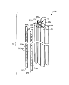
[00103] Figure 15 depicts an exploded front perspective view of an exemplary
embodiment of
one of the vertical uprights 118. Figure 16 is an assembled cross-sectional
view of the vertical
upright 118 shown in Figure 15. The vertical upright 118 can include a frame
portion 190 and a
power track insert portions 206 and 208. As shown in Figure 15, the frame
portion 190 can have
an elongated body having a generally planar rear surface portion 192
configured to mount flush
with cross bars (e.g., cross bars 124, 124', 124", 124", 128, 128', 128",
128") and a multi-
channeled front portion 211. The power track insert portions 206 and 208 can
have generally
planar elongate bodies 207 and 209, respectively. The bodies 207 and 209 can
each have
openings 210 formed therein, which can be distributed along a length of the
bodies 207 and 209.
In exemplary embodiments, the frame portion 190 can be formed from an
electrically insulating
or electrically non-conductive material, such as a polymer (e.g., plastic),
and the power track
insert portions 206 and 208 can each be formed from an electrical conductive
material, such as
metal.
[00104] Referring
to Figures 15 and 16, the multi-channeled front portion 211 of the frame
portion 190 can have a first pair of channels including a channel 194 and a
channel 200, a second
pair of channels including a channel 196 and a channel 202, a third pair of
channels including a
channel 197 and a channel 203, and a fourth pair of channels including a
channel 198 and a
channel 204. The first through fourth pairs of channels can be formed by arms
181, 195, 199,
which generally extend perpendicularly outward from the planar rear surface
192 at an interface
between a first end 205 of the arms 181, 195, 199 and the planar rear surface
192. A second end
213 of the arms 181, 195, 199 can include contours that form the first through
fourth pairs of
channels.
[00105] The channels 194 and 200 that form the first pair of channels can be
formed between
the planar rear surface 192 and the arms 181 and 199. For example, the arms
181 and 195 and
the rear planar surface 192 can form the channel 194 and the arms 195 and 199
and the rear
planar surface 192 can form the channel 200. As depicted in Figures 15 and 16,
the channels 194
and 200 can be U-shaped channels that open outwardly away from the planar rear
surface 192
towards the second end 213 and can receive a portion of shelf assemblies as
described in more
detail herein.
22
CA 02875583 2014-12-23
[00106] The channels 196 and 202 that form the second pair of channels can be
formed
between the arms 181 and 195 within the channel 194. The channels 196 and 202
can be spaced
away from the rear planar surface 192 and can be perpendicular to the channel
194. As depicted
in Figures 15 and 16, the channel 196 can be formed by the arm 181 and the
channel 202 can be
formed by the arm 195. The channels 196 and 202 can be opposingly spaced U-
shaped channels
that open towards each other. In exemplary embodiments, as depicted in Figure
16, the channels
196 and 202 can be configured to receive the power track insert portion 206
such that the
channels 196 and 202 retain the power track insert portion 206 in the multi-
channel front portion
211 in parallel relation to the rear planar surface 192.
[00107] The channels 197 and 203 that form the third pair of channels can be
formed between
the arms 195 and 199 within the channel 200. The channels 197 and 203 can be
spaced away
from the rear planar surface 192 and can be perpendicular to the channel 200.
As depicted in
Figures 15 and 16, the channel 197 can be formed by the arm 199 and the
channel 203 can be
formed by the arm 195. The channels 197 and 203 can be opposingly spaced U-
shaped channels
that open towards each other. In exemplary embodiments, as depicted in Figure
16, the channels
197 and 203 can be configured to receive the power track insert portion 208
such that the
channels 197 and 203 retain the power track insert portion 208 in the multi-
channel front portion
211 in parallel relation to the rear planar surface 192 and in a plane that
includes the power track
insert 206.
[00108] The channels 198 and 204 that form the fourth pair of channels can be
formed by the
arms 181 and 199, respectively, and can be distanced further away from the
rear planar surface
than the second and third pairs of channels such that the power track insert
portions 206 and 208
can be recessed with respect to the channels 198 and 204 when the power track
insert portions
206 and 208 are inserted into the second and third pairs of channels,
respectively. The channels
198 and 204 can be opposingly spaced J-shaped channels that open away from
each other and in
parallel with the channels 196 and 202 of the second"pair of channels, with
the channels 197 and
203 of the second pair of channels, and with the rear planar surface 192. The
channel 198 can be
configured to receive and selectively retain a side edge of a first front
panel and the channel 204
can be configured to receive and selectively retain a side edge of a second
front panel to hold the
first and second front panels in a common plane with respect to the vertical
upright 118.
23
CA 02875583 2014-12-23
[00109] The J-shape of the channel 198 can be formed by wall portion 226, 227,
and 228.
The wall portion 226 can be formed by the arm 181 and can have a terminal end
221 and
connecting end 217. The wall portion 226 can be spaced away from and extend
parallel to the
rear planar surface 192. The wall portion 227 is formed by the arm 181 and
extends
perpendicularly to and away from the rear planar surface 192 from the
connecting end 217 of the
wall portion 226 to a connecting end 219 of the wall portion 228, which is
formed by the arm
181 and extends from the connecting end 219 to a terminal end 223 in parallel
to the rear planar
surface 192 and the wall portion 226, and in a common direction as the wall
portion 226. The
wall portion 228 has a length that is less than the length of the wall portion
226.
[00110] The J-shape of the channel 204 can be formed by wall portion 214, 215,
and 216.
The wall portion 214 can be formed by the arm 199 and can have a terminal end
229 and
connecting end 231. The wall portion 214 can be spaced away from and extend
parallel to the
rear planar surface 192. The wall portion 215 is formed by the arm 199 and
extends
perpendicularly to and away from the rear planar surface 192 from the
connecting end 231 of the
wall portion 214 to a connecting end 233 of the wall portion 216, which is
formed by the arm
199 and extends from the connecting end 239 to a terminal end 237 in parallel
to the rear planar
surface 192 and the wall portion 214, and in a common direction as the wall
portion 214. The
wall portion 216 has a length that is less than the length of the wall portion
214.
[00111] In exemplary embodiments, each of the power track insert portions 206
and 208 have
a retaining member 363, 364 formed proximate to at least one end of the bodies
207 and 209.
When the power track insert portions 206 and 208 are inserted into the second
and third pairs of
channels, respectively, each retaining member 363, 364 can be aligned with a
hole 365 formed in
the arm 195 of the frame portion 190. A fastening member 222 can be insert
through each hole
365 to engage the retaining members 363, 364 of the power track insert
portions 206 and 208 to
lock the power track insert portions 206 and 208 in place in the frame portion
190. The power
track insert portion 206 and the power track insert portion 208 can be
disposed within the multi-
channel front portion 211 of the frame to obstruct the cavities formed by the
channel 194 and
200, which can be accessible via the openings 210 formed in the power track
insert portions 206
and 208. For example, electrically conductive arms of shelf assemblies can
engage and extend
through the openings 210 into the cavities of the channels 194 and 200 to
selectively retain the
24
CA 02875583 2014-12-23
shelf assemblies to the vertical upright 118' and place the electrical
conductive arms in electrical
contact with the power track inserts 206 or 208 so that electricity can flow
to or from the shelf
assemblies through the power track insert portions 206 or 208.
[00112] Figure 18 depicts an exploded front perspective view of an exemplary
embodiment of
one of the vertical uprights 118'. Figure 17 is an assembled cross-sectional
view of the vertical
upright 118' shown in Figure 18. The vertical upright 118' can include a frame
portion 190' and
a power track insert portions 206' and 208'. As shown in Figure 18, the frame
portion 190' can
have an elongated body having a generally planar rear surface portion 192'
configured to mount
flush with cross bars (e.g., cross bars 124, 124', 124", 124", 128, 128',
128", 128'") and a
multi-channeled front portion 211'. The power track insert portions 206' and
208' can have
generally planar elongate bodies 207' and 209', respectively. The bodies 207'
and 209' can each
have openings 210' formed therein, which can be distributed along a length of
the bodies 207'
and 209'. In exemplary embodiments, the frame portion 190' can be formed from
an electrically
insulating or electrically non-conductive material, such as a polymer (e.g.,
plastic), and the
power track insert portions 206' and 208' can each be formed from an
electrical conductive
material, such as metal.
[00113] Referring
to Figures 17 and 18, the multi-channeled front portion 211' of the frame
portion 190' can have a first pair of channels including a channel 194' and a
channel 200' and a
second pair of channels including a channel 198' and a channel 204'. The first
and second pairs
of channels can be formed by arms 181', 195', 199', which generally extend
perpendicularly
outward from the planar rear surface 192' at an interface between a first end
205' of the arms
181', 195', 199' and the planar rear surface 192'. A second end 213' of the
arms 181', 195',
199' can include contours that form the first and second pairs of channels.
[00114] The channels 194' and 200' that form the first pair of channels can be
formed
between the planar rear surface 192' and the arms 181' and 199'. For example,
the arms 181'
and 195' and the rear planar surface 192' can form the channel 194' and the
arms 195' and 199'
and the rear planar surface 192' can form the channel 200'. As depicted in
Figures 17 and 18,
the channels 194' and 200' can be U-shaped channels that open outwardly away
from the planar
rear surface 192' towards the second end 213' and can receive a portion of
shelf assemblies as
CA 02875583 2014-12-23
described in more detail herein. In exemplary embodiments, as = depicted in
Figure 17, the
channels 194' and 200' can be configured to receive the power track insert
portion 206 such that
the channels 194' and 200' retain the power track insert portion 206' in the
multi-channel front
portion 211'.
100115] The channels 198' and 204' that form the second pair of channels can
be formed by
the arms 181' and 199', respectively, and can be spaced apart from the rear
planar surface 192'
such that the power track insert portions 206' and 208' can be recessed with
respect to the
channels 198' and 204' when the power track insert portions 206' and 208' are
inserted into
channels 194' and 200' respectively. The channels 198' and 204' can be
opposingly spaced J-
shaped channels that open away from each other and in parallel with the rear
planar surface 192.
The channel 198' can be configured to receive and selectively retain a side
edge of a first front
panel and the channel 204' can be configured to receive and selectively retain
a side edge of a
second front panel to hold the first and second front panels in a common plane
with respect to the
vertical upright 118'.
[00116] The J-shape of the channel 198' can be formed by wall portion 226',
227', and 228'.
The wall portion 226' can be formed by the arm 181' and can have a terminal
end 221' and
connecting end 217'. The wall portion 226' can be spaced away from and extend
parallel to the
rear planar surface 192'. The wall portion 227' is formed by the arm 181' and
extends
perpendicularly to and away from the rear planar surface 192' from the
connecting end 217' of
the wall portion 226' to a connecting end 219' of the wall portion 228', which
is formed by the
arm 181' and extends from the connecting end 219' to a terminal end 223' in
parallel to the rear
planar surface 192' and the wall portion 226', and in a common direction as
the wall portion
226'. The wall portion 228' has a length that is less than the length of the
wall portion 226'.
[00117] The J-
shape of the channel 204' can be formed by wall portion 214', 215', and 216'.
The wall portion 214' can be formed by the arm 199' and can have a terminal
end 229' and
connecting end 231'. The wall portion 214' can be spaced away from and extend
parallel to the
rear planar surface 192'. The wall portion 215' is formed by the arm 199' and
extends
perpendicularly to and away from the rear planar surface 192' from the
connecting end 231' of
the wall portion 214' to a connecting end 233' of the wall portion 216', which
is formed by the
26
CA 02875583 2014-12-23
arm 199' and extends from the connecting end 239' to a terminal end 237' in
parallel to the rear
planar surface 192' and the wall portion 214', and in a common direction as
the wall portion
214'. The wall portion 216' has a length that is less than the length of the
wall portion 214'.
[00118] In exemplary embodiments, each of the power track insert portions 206'
and 208'
have a retaining member 363' (not shown), 364' formed proximate to at least
one end of the
bodies 207' and 209'. When the power track insert portions 206' and 208' are
inserted into'
channels 194' and 200', respectively, each retaining member 363'. 364' can be
aligned with a
hole 365' formed in the arms 181', 199' of the frame portion 190'. A fastening
member 222'
can be inserted through each hole 365' to engage the retaining members 363',
364' of the power
track insert portions 206' and 208' to lock the power track insert portions
206' and 208' in place
in the frame portion 190'. The power track insert portion 206' and the power
track insert
portion 208' can be U-shaped and disposed within the multi-channel front
portion 211' of the
frame to obstruct the openings of U-shaped channels 194' and 200', which can
be accessible via
the openings 210' formed in the power track insert portions 206' and 208'. For
example,
electrically conductive arms of shelf assemblies can engage and extend through
the openings
210' into the cavities of the channels 194' and 200' to selectively retain the
shelf assemblies to
the vertical upright 118' and place the electrically conductive arms in
electrical contact with the
power track inserts 206' or 208' so that electricity can flow to or from the
shelf assemblies
through the power track insert portions 206' or 208'.
[00119] Figure 19A depicts a front perspective view of an exemplary embodiment
of one of
the vertical uprights 118 that forms a left upright end assembly of the wall
assembly. Figure 20A
is an assembled top view of the vertical upright 118 of figure 19A. As shown
in Figure 19A, a
frame portion 232 of the vertical upright 118 can have an elongated body
having a generally
planar rear surface portion 234 configured to mount flush with cross bars
(e.g., cross bars 124,
124', 124", I24", 128, 128', 128", 128") and a multi-channeled front portion
241. The
vertical upright 118 can include the frame portion 232 and a slotted power
track insert portion
260 as shown in Figure 20A. The slotted power track insert portion 260 has a
similar structure
as the power track insert portion 206 depicted in Figures 15 and 16. In
exemplary embodiments,
the frame portion 232 can be formed from an electrically insulating or
electrically non-
27
CA 02875583 2014-12-23
conductive material, such as a polymer (e.g., plastic), and the power track
insert portion 260 can
each be formed from an electrical conductive material, such as metal.
[00120] Referring to Figures 19A and 20A, the multi-channeled front portion
241 of the frame
portion 232 can have a first channel 236, a second channel 253, a third 255,
and a fourth channel
266. The first channel 236 can be formed by arms 245 and 247, which generally
extend
perpendicularly outward from the planar rear surface 234 at an interface
between a first end 249
of the arms 245 and 247, and the planar rear surface 234. A second end 251 of
the arms 245 and
247 can include contours that form the second through fourth channels 253,
255, and 266.
[00121] The first channel 236 can be formed between the planar rear surface
234 and the arms
245 and 247. For example, the arms 245 and 247 and the rear planar surface 234
can form the
channel 236. As depicted in Figures 19A and 20A, the channel 236 can be U-
shaped that opens
outwardly away from the planar rear surface 234 and towards the second end
251. The first
channel 236 can be configured to receive a portion of the shelf assemblies as
described in more
detail herein.
[00122] The channels 253 and 255 form a pair of channels between the arms 245
and 247
within the channel 236. The channels 253 and 255 can be spaced away from the
rear planar
surface 234 and can be perpendicular to the channel 236. As depicted in
Figures I 9A and 20A,
the channel 253 can be formed by the arm 247 and the channel 255 can be formed
by the arm
245. The channels 253 and 255 can be opposingly spaced U-shaped channels that
open towards
each other. In exemplary embodiments, as depicted in Figure 20A, the channels
253 and 255 can
be configured to receive the power track insert portion 260 such that the
channels 253 and 255
retain the power track insert portion 260 in the multi-channel front portion
241 in parallel
relation to the rear planar surface 234 and in a plane that includes the power
track insert 260.
[00123] The fourth channel 266 extends from the arm 245, and can be distanced
further away
from the rear planar surface than the second and third pairs of channels such
that the power track
insert portions 260 can be recessed with respect to the channel 266 when the
power track insert
portion 260 is inserted into the second and third pairs of channels,
respectively. The channel 266
can he a J-shaped channel in parallel with channels 253 and 255 , and with the
rear planar
28
CA 02875583 2014-12-23
surface 234. The channel 266 can be configured to receive and selectively
retain a side edge of a
front panel to hold the front panel in a common plane with respect to the
vertical upright 118'.
[00124] The J-shape of the channel 266 can be formed by wall portion 264, 265,
and 267.
The wall portion 267 can be formed by the arm 245 and can have a terminal end
269 and
connecting end 270. The wall portion 267 can be spaced away from and extend
parallel to the
rear planar surface 234. The wall portion 265 is formed by the arm 245 and
extends
perpendicularly to and away from the rear planar surface 234 from the
connecting end 270 of the
wall portion 264 to a connecting end 273 of a wall portion 267, which is
formed by the arm 264
and extends from the connecting end 273 to a terminal end 274 in parallel to
the rear planar
surface 234 and the wall portion 265, and in a common direction as the wall
portion 267. The
wall portion 264 has a length that is less than the length of the wall portion
267.
[00125] Figure 19B depicts a front perspective view of an exemplary embodiment
of one of
the vertical uprights 118' that forms a left upright end assembly of the wall
assembly. Figure
20B is an assembled top view of the vertical upright 118' of figure 19B. As
shown in Figure
19B, a frame portion 232' of the vertical upright 118' can have an elongated
body having a
generally planar rear surface portion 234' configured to mount flush with
cross bars (e.g., cross
bars 124, 124', 124", l24", 128, 128', 128", 128¨) and a multi-channeled front
portion 241'.
The vertical upright 118' can include the frame portion 232' and a slotted
power track insert
portion 260' as shown in Figure 20B. The slotted power track insert portion
260' has a similar
structure as the power track insert portion 206' depicted in Figures 17 and
18. In exemplary
embodiments, the frame portion 232' can be formed from an electrically
insulating or electrically
non-conductive material, such as a polymer (e.g., plastic), and the power
track insert portion
260' can each be formed from an electrical conductive material, such as metal.
[00126] Referring
to Figures 19B and 20B, the multi-channeled front portion 241' of the
frame portion 232' can have a first channel 236' and a second channel 266. The
first channel
236' can be formed by arms 245' and 247', which generally extend
perpendicularly outward
from the planar rear surface 234' at an interface between a first end 249' of
the arms 245' and
247', and the planar rear surface 234'. A second end 251' of arms 245' can
include contours that
form the second channel 266'.
29
CA 02875583 2014-12-23
[00127] The first channel 236' can be formed between the planar rear surface
234' and the
arms 245' and 247'. For example, the arms 245' and 247' and the rear planar
surface 234' can
form the channel 236'. As depicted in Figures 19B and 20B, the channel 236'
can be U-shaped
that opens outwardly away from the planar rear surface 234' and towards the
second end 251'.
The first channel 236' can be configured to receive a portion of the shelf
assemblies as
described in more detail herein. In exemplary embodiments, as depicted in
Figure 2011, the
channel 236' can be configured to receive the power track insert portion 260'
such that the
channel 236' retains the power track insert portion 260' in the multi-channel
front portion 241'.
[00128] The second channel 266' extends from the arm 245', and can be spaced
apart from
the rear planar surface 234' such that the power track insert portions 260'
can be recessed with
respect to the channel 266' when the power track insert portion 260' is
inserted into the first
channel 236'. The channel 266' can be a J-shaped channel in parallel with the
rear planar
surface 234'. The channel 266' can be configured to receive and selectively
retain a side edge of
a front panel to hold the front panel in a common plane with respect to the
vertical upright 118'.
[00129] The J-shape of the channel 266' can be formed by wall portion 264',
265', and 267'.
The wall portion 267' can be formed by the arm 245' and can have a terminal
end 269' and
connecting end 270'. The wall portion 267' can be spaced away from and extend
parallel to the
rear planar surface 234'. The wall portion 265' is formed by the arm 245' and
extends
perpendicularly to and away from the rear planar surface 234' from the
connecting end 270' of
the wall portion 264' to a connecting end 273' of a wall portion 267', which
is formed by the
arm 264' and extends from the connecting end 273' to a terminal end 274' in
parallel to the rear
planar surface 234' and the wall portion 265', and in a common direction as
the wall portion
267'. The wall portion 264' has a length that is less than the length of the
wall portion 267'.
[00130] Figure 21A depicts a front perspective view of an exemplary embodiment
of one of
the vertical uprights 118 that forms a right track upright of the wall
assembly. Figure 22A is an
assembled top view of the vertical upright 118 of Figure 21A. As shown in
Figure 21A, a frame
portion 242 of the vertical upright 118 can have an elongated body having a
generally planar rear
surface portion 244 configured to mount flush with cross bars (e.g., cross
bars 124, 124', 124",
124", 128, 128', 128", 128") and a multi-channeled front portion 271. The
vertical upright
CA 02875583 2014-12-23
118 shown in Figures 21A and 22A can include a frame portion 242 and a slotted
power track
insert portion 252. As shown in Figure 22A the slotted power track insert
portion 252 has a
similar structure as the power track insert portion 208 depicted in Figures 15
and 16. In
exemplary embodiments, the frame portion 242 can be formed from an
electrically insulating or
electrically non-conductive material, such as a polymer (e.g., plastic), and
the power track insert
portion 252 can each be formed from an electrical conductive material, such as
metal.
[00131] Referring to Figures 21A and 22A, the multi-channeled front portion
271 of the frame
portion 242 can have a first channel 248, a second channel 246, a third
channel 254, and a fourth
channel 278. The first channel can be formed by arms 268 and 286, which
generally extend
perpendicularly outward from the planar rear surface 244 at an interface
between a first end 258
of the arms 268 and 286, and the planar rear surface 244. A second end 250 of
the arms 268 and
286 can include contours that form the second through fourth pairs of channels
246,254, 278.
[00132] The second channel 246 can be formed between the planar rear surface
244 and the
arms 268 and 286. For example, the arms 268 and 286 and the rear planar
surface 244 can form
the channel 246. As depicted in Figures 21A and 22A, the channel 246 can be U-
shaped that
opens outwardly away from the planar rear surface 244 and towards the second
end 250. The
second channel 246 can be configured to receive a portion of the shelf
assemblies as described in
more detail herein.
[00133] The channels 257 and 259 forms a pair of channels between the arms 268
and 286
within the channel 246. The channels 257 and 259 can be spaced away from the
rear planar
surface 244 and can be perpendicular to the channel 246. As depicted in
Figures 21A and 22A,
the channel 257 can be formed by the arm 286 and the channel 259 can be formed
by the arm
268. The channels 257 and 259 can be opposingly spaced U-shaped channels that
open towards
each other. In exemplary embodiments, as depicted in Figure 22A, the channels
257 and 259 can
be configured to receive the power track insert portion 252 such that the
channels 257 and 259
retain the power track insert portion 252 in the multi-channel front portion
271 in parallel
relation to the rear planar surface 244 and in a plane that includes the power
track insert 252.
[00134] The fourth channel 278 can be formed by the arm 268, and can be
distanced further
away from the rear planar surface than the second and third pairs of channels
such that the power
31
CA 02875583 2014-12-23
track insert portions 252 can be recessed with respect to the channel 278 when
the power track
insert portion 252 is inserted into the second and third pairs of channels,
respectively. The
channel 278 can be a J-shaped channel in parallel with channel 254 of the
second channel, and
with the rear planar surface 244. The channel 278 can be configured to receive
and selectively
retain a side edge of a front panel to hold the front panel in a common plane
with respect to the
vertical upright 118.
[00135] The J-shape of the channel 278 can be formed by wall portion 276, 262,
and 280.
The wall portion 276 can be formed by the arm 268 and can have a terminal end
277 and
connecting end 279. The wall portion 276 can be spaced away from and extend
parallel to the
rear planar surface 244. The wall portion 262 is formed by the arm 268 and
extends
perpendicularly to and away from the rear planar surface 244 from the
connecting end 281 of the
wall portion 262 to a connecting end 283 of a wall portion 280, which is
formed by the arm 280
and extends from the connecting end 287 to a terminal end 285 in parallel to
the rear planar
surface 244 and the wall portion 276, and in a common direction as the wall
portion 276. The
wall portion 280 has a length that is less than the length of the wall portion
267.
[00136] Figure 21B depicts a front perspective view of an exemplary embodiment
of one of
the vertical uprights 118' that forms a right track upright of the wall
assembly. Figure 22B is an
assembled top view of the vertical upright 118' of Figure 21B. As shown in
Figure 21B, a frame
portion 242' of the vertical upright 118' can have an elongated body having a
generally planar
rear surface portion 244' configured to mount flush with cross bars (e.g.,
cross bars 124, 124',
124", 124", 128, 128', 128¨, 128") and a multi-channeled front portion 271'.
The vertical
upright 118' shown in Figures 21B and 22B can include a frame portion 242' and
a slotted
power track insert portion 252'. As shown in Figure 22B the slotted power
track insert portion
252' has a similar structure as the power track insert portion 208' depicted
in Figures 17 and 18.
In exemplary embodiments, the frame portion 242' can be formed from an
electrically insulating
or electrically non-conductive material, such as a polymer (e.g., plastic),
and the power track
insert portion 252' can be formed from an electrical conductive material, such
as metal.
[00137] Referring to Figures 21B and 22B, the multi-channeled front portion
271' of the
frame portion 242' can have a first channel 248', a second channel 246', and a
third channel 278.
32
CA 02875583 2014-12-23
The first channel can be formed by arms 268' and 286', which generally extend
perpendicularly
outward from the planar rear surface 244' at an interface between a first end
258' of the arms
268' and 286', and the planar rear surface 244'. A second end 250' of the arms
268' and 286'
can include contours that form the second and third pairs of channels 246',
278'.
[00138] The second channel 246' can be formed between the planar rear surface
244' and the
arms 268' and 286'. For example, the arms 268' and 286' and the rear planar
surface 244' can
form the channel 246'. As depicted in Figures 21B and 22B, the channel 246'
can be U-shaped
and open outwardly away from the planar rear surface 244' and towards the
second end 250'.
The second channel 246' can be configured to receive a portion of the shelf
assemblies as
described in more detail herein. In exemplary embodiments, as depicted in
Figure 22B, the
channel second channel 246' can be configured to receive the power track
insert portion 252'
such that the channel 246' retains the power track insert portion 252' in the
multi-channel front
portion 271'.
[00139] The third channel 278' can be formed by the arm 268', and can be
spaced apart from
the rear planar surface 244' such that the power track insert portions 252'
can be recessed with
respect to the channel 278' when the power track insert portion 252' is
inserted into the second
channel 246'. The channel 278' can be a J-shaped channel in parallel with the
rear planar
surface 244'. The channel 278' can be configured to receive and selectively
retain a side edge of
a front panel to hold the front panel in a common plane with respect to the
vertical upright 118'.
[00140] The J-shape of the channel 278' can be formed by wall portions 276',
262', and 280'.
The wall portion 276' can be formed by the arm 268' and can have a terminal
end 277' and
connecting end 279'. The wall portion 276' can be spaced away from and extend
parallel to the
rear planar surface 244'. The wall portion 262' is formed by the arm 268' and
extends
perpendicularly to and away from the rear planar surface 244' from the
connecting end 281' of
the wall portion 262' to a connecting end 283' of a wall portion 280', which
is formed by the
arm 280' and extends from the connecting end 287' to a terminal end 285' in
parallel to the rear
planar surface 244' and the wall portion 276', and in a common direction as
the wall portion
276'. The wall portion 280' has a length that is less than the length of the
wall portion 267'.
33
CA 02875583 2014-12-23
[00141] Figure 23 depicts an exemplary cooperative engagement between a
vertical upright
and a cross bar assembly. As shown in Figure 23, the lower wall assembly 288
includes a lower
cross bar 128, a left vertical upright 232, a double vertical upright 190, and
a back panel 142. In
the present embodiment, the left vertical upright 232 and the double vertical
upright 190 can be
fully seated with the bottom edge of the left vertical upright 290 and the
double vertical upright
296 flush mounted against the bottom lip 294 of the lower cross bar 128. The
front hook 172 can
align with and extend through openings 117 in the left vertical upright 232
and the double
vertical upright 190 to create a vertical offset between the opening 117 so
that the hook 172
abuts a surface of the body of the vertical upright 232 and 190 to selectively
retain the vertical
upright 232, 190 to the crossbar.
[00142] Figure 24 depicts an exemplary embodiment of the power supply 126
being mounted
to the back panel 142 of the vertical support structure. In some embodiments
the power supply
126 can be operatively coupled to the cross bar 124 and can be configured to
provide electricity
to the merchandise display wall system 100. For example, a power supply
bracket 298 can be
detachably coupled to the cross bar 124 and the power supply 126 can be
mounted to the bracket
298. In some embodiments, the power supply 126 can be operatively coupled to
the lower cross
bar 128 or the back panel 142. The power supply 126 can be reset, removed or
rearranged, with
the vertical uprights 118 and cross bars 124, 128 or independent of the
vertical uprights 118 and
the cross bars 124, 128. Reconfiguration can be used to adapt to new power
requirements of
product displays or to adapt to retail facility resets.
[00143] Figure 25
depicts a front perspective view illustrating an attachment of the front
panels 120 to the wall assembly 130. In some embodiments the front panel 120
can be
operatively coupled to the vertical uprights 118. For example, as described
above, the vertical
uprights include J-channels that are configured to receive a side edge of
front panels 120. For J-
channels of adjacent vertical uprights can each receive a side edge of one of
the front panels 120
by sliding or snapping the front panel into the J-channels from a vertical or
horizontal position.
As such, the J-channels of adjacent vertical uprights can provide a track for
retaining the front
panels. In some embodiments, the front panel 120 may have a uniform front
surface extending
from the top edge to the bottom edge of thse back panel 142.
34
CA 02875583 2014-12-23
[00144] In some embodiments, at least one of the front panels 120 may have a
knock out 300
to provide access to a component positioned on the back panel 142 or cross
bars 124, 128, such
as the power supply 126 or the like. In some embodiments, the knock out 300
can be positioned
along the top edge, bottom edge, side edge, or without contacting any edges of
the front panel in
which the knock is formed. In exemplary embodiments, the merchandise display
wall system
100 can have a reconfigurable arrangement allowing for one or more of the
front panels 120 to
be reset, removed or rearranged, either as group or independent of one
another. In exemplary
embodiments, the panel 120 can be formed of a plastic material or an alternate
electrically
isolating material.
[00145] Figure 26 depicts an exemplary embodiment of top caps 122 being
operatively
coupled to the wall assembly 130. The top caps 122 can each include an
elongate housing 325
and an electric harness 310. The elongate housing 325 of the top caps 122 can
be formed using
any suitable materials including, plastic, fiberglass, and the like. In
exemplary embodiments, the
top cap 122 can be coupled to the wall assembly 130, by placing the elongate
housing 325 of top
caps 122 perpendicular to the vertical uprights 118 and the front panels 120
and operatively
coupling the top caps 122 to the vertical uprights 118. The harness 310 of the
top caps 122 can
be configured to provide electricity to the merchandise display wall system
100 from the power
supply 126. For example, the harnesses can receive electricity from the power
supply 126 and
can be in electrical contact with the power track insert portions of the
vertical uprights to provide
electricity to the vertical uprights. The top caps 122 can be detachably
coupled to the vertical
uprights by a friction fit, a snap fit, or the like.
[00146] Figures
27 and 28 illustrate the structure of the top cap and depict how and where it
attached to the wall assembly 130. Figure 27 depicts an exemplary embodiment
of a front
perspective view of the top cap configured to engage the wall assembly. Figure
28 depicts a
more detailed view of a portion of the top cap features shown in figure 27. As
shown in Figure
28, the top cap connects to the conducting portion of the vertical upright
(e.g., power track insert
portions 206, 208, or both).
1_00147] In an exemplary embodiment, with reference to Figures 27 and 28, the
housing 325 of
the top cap 122 can include a front surface 314 configured to fit around the
perimeter of the wall
CA 02875583 2014-12-23
assembly 130, including the vertical uprights 118 and the front panels 120. A
rear surface 309
can include cut outs 312 configured to provide ports for the wire harness 310
to enter and exit the
housing 325. The wiring harness 310 can be operatively coupled to the power
supply 126 to
supply power from the power supply 126 to the power track insert portions of
the vertical
uprights 118, while the frame portion of the vertical uprights electrically
insulates the power
insert track portions from the other components of the wall assembly 130. The
top cap 122 can
be configured with electrical contacts 308 that can be detachably and
electrically coupled to the
vertical uprights 118. For example, in some embodiments, electrical contacts
308 coupled to the
wire harness 310. The electrical contacts 308 can be in electrical contact
with a pair of adjacent
vertical uprights of the wall assembly 130 (e.g., one of the electrical
contacts 308 can be
electrically coupled to a power track insert portion in one of the vertical
uprights in the pair and
one of the electrical contacts 308 in the top cap 122 can be electrically
coupled to a power track
insert portion in the other vertical upright in the pair). In exemplary
embodiments, the power
supply 126 may provide power to one or more of the top caps 122 of the wall
assembly 130. For
example, in some embodiments, the wire harnesses 310 of the top caps 122 can
be connected in
series with each other and with the power supply 126, as described in more
detail below.
[00148] Referring
still to Figures 27 and 28, once the wire harness 310 is electrically coupled
to the power supply 126 and one or more vertical uprights 118, the power
supply 126 can
provide electricity or power to a shelf assembly to power the shelf assembly.
For example, the
shelf assembly can include electrical circuitry to illuminate one or more
areas of the wall
assembly 130 such that electricity from the power supply can flow through the
wire harness 308
of the top cap 122 and one or more power track insert portions of one or more
vertical uprights
118 and to the shelf assembly to energize the electrical circuitry.
[00149] Figure 29 depicts an exploded view of an exemplary embodiment of the
top cap 122
of the wall assembly 130. Referring to Figure 29, the housing 325 of the top
cap 122 can include
a front surface 314, a top surface 326, a rear surface 328 and end walls 318.
In some
embodiments, the front surface 314 of the top cap 122 can extend along the
horizontal axis in a
generally linear manner. The side walls 318 can extend between the front
surface 314 and the
rear surface 328. The side walls 318 can extend from the top surface 326
downward, terminating
36
CA 02875583 2014-12-23
before the bottom edge of the side wall becomes flush with the bottom edge of
the front surface
314 and the rear surface 328.
[00150] A wire assembly of the top cap 122 includes the wiring harness 310, or
anywhere in
between mating electrical connectors 324, electrical contacts 308 and external
connectors 322.
The mating electrical connectors 324 can be disposed at terminal ends of the
wiring harness 310
and can be detachably coupled to the electrical contacts 308. The wire harness
310 can be
operatively coupled to the housing 325 of the top cap 122 with fasteners 330,
such as rivets,
screws, bolts, or the like. For example, in some embodiments, the electrical
contacts 308 can
include a hole 311 that is configured to align with a hole 331 formed in the
top surface 326 of the
housing 325. The fastener can be configured to extend through the top surface
326 and engage
the hole 311 in the electrical contact 308 to secure the assembled wire
harness 308 to the housing
325. The electrical contacts 308 can be electrically coupled to mating
connector 324 formed by
a pair of resilient prongs. In some embodiments, the mating connector 324 can
be configured to
directly engage the power track insert portions of a vertical upright to
secure the top cap 122 to
the wall assembly 130 and provide electrical power to the power track insert
portions.
1001511 The external connectors 322 can be configured to electrically connect
the top cap 122
to other top caps 122 and to a power supply (e.g., the power supply 126). In
some embodiments,
the top cap 122 can include two of the external connectors 322, where a first
one of the external
connectors can be connected to receive electricity from a component, such as a
power supply or
another top cap and a second one of the external connectors 322 can be
configured to provide
electricity flowing through the top cap to another component, such as another
top cap 122.
[00152] Figure 30 depicts a bottom perspective view of an exemplary embodiment
of an
interior of an assembled top cap. The wiring harness 310 can be configured to
the second
connector 322, which can be coupled to a power supply. The wiring harness 310
can extend
from the rear surface 326 through wire knockouts 312. Within the top cap 122
the wiring
harness 310 can be disposed to extend the length of the inner cavity. The
electrical connectors
308 can be detachably coupled to the mating connector 324 and can be disposed
proximate to the
side walls 318 of the top cap.
37
CA 02875583 2014-12-23
[00153] Figure 31 depicts an exploded view of an exemplary embodiment of the
top cap 122'
of the wall assembly. Referring to Figure 31, the housing 325' of the top cap
122' can include a
front surface 314', a top surface 326', a rear surface 328' and end walls
318'. In some
embodiments, the front surface 314' of the top cap 122' can extend along the
horizontal axis in a
generally linear manner. The side walls 318' can extend between the front
surface 314' and the
rear surface 328'. The side walls 318' can extend from the top surface 326'
downward,
terminating before the bottom edge of the side wall becomes flush with the
bottom edge of the
front surface 314' and the rear surface 328'.
[00154] A wire assembly of the top cap 122' includes the wiring harness 310',
or anywhere in
between mating electrical connectors 324', electrical contacts 308' and
external connectors 322'.
The mating electrical connectors 324' can be disposed at terminal ends of the
wiring harness
310' and can be detachably coupled to the electrical contacts 308'. The wire
harness 310' can be
operatively coupled to the housing 325' of the top cap 122' with fasteners
330', such as rivets,
screws, bolts, or the like. For example, in some embodiments, the electrical
contacts 308' can
include a hole 311' that is configured to align with a hole 331' formed in the
top surface 326' of
the housing 325'. The fastener can be configured to extend through the top
surface 326' and
engage the hole 311' in the electrical contact 308' to secure the assembled
wire harness 308' to
the housing 325'. The electrical contacts 308' can be electrically coupled to
mating connector
324' formed by a pair of resilient prongs. In some embodiments, the mating
connector 324' can
be configured to directly engage the power track insert portions of a vertical
upright to secure the
top cap 122' to the wall assembly and provide electrical power to the power
track insert portions.
[00155] The external connectors 322' can be configured to electrically connect
the top cap
122' to other top caps 122' and to a power supply (e.g., the power supply
126). In some
embodiments, the top cap 122' can include two of the external connectors 322',
where a first one
of the external connectors can be connected to receive electricity from a
component, such as a
power supply or another top cap and a second one of the external connectors
322' can be
configured to provide electricity flowing through the top cap to another
component, such as
another top cap 122'.
CA 02875583 2014-12-23
[00156] Figure 32 depicts a rear perspective view of an exemplary embodiment
of a portion of
the wall assembly 130 showing electrical connections between the top caps 122a-
d of the wall
assembly. The vertical support structure 132 has been omitted from Figure 32
to show a
connection between other components of the wall assembly 130. As depicted in
Figure 32, the
cross bar 124 can be configured to receive the vertical uprights 118 and the
power supply bracket
298. The power supply 126 can be detachably coupled to the power supply
bracket 298. A front
panel 120 can be detachably coupled to the vertical uprights 118.
[00157] In an exemplary embodiment, the top caps 122a-d can be detachably
coupled to the
top of the vertical uprights 118. The wiring harnesses 310a-d can extend from
the top caps 122a-
d, through wire knockouts 312, toward the rear side of the merchandise display
wall system 100.
The wire harnesses 310a-d can be electrically coupled to the power supply 126
to receive power
from the power supply 126 and to provide power to the vertical uprights 118.
In some
embodiments, the wiring harnesses 310a-d can be connected in series with each
other. The
wiring harnesses 310a-d can be detachably coupled to each other via the
external connectors
322a-d. For example, detachably coupling several harnesses 310a-d via the
external connectors
322a-d can provide power to the top caps 122a-d and vertical uprights 118 from
a single power
supply.
[00158] As
depicted in Figure 32, the power supply 126, top caps 122a-d, and vertical
uprights 118 can be connected. As described below with reference to Figure 33,
shelf assemblies
can be connected between adjacent vertical uprights 118 to complete the series
circuit. To form
the series circuit, an input to the power supply 126 can be received via an
electrical outlet or
terminal and an output of the power supply 126 can be connected to the top cap
1 22a via one of
the external connectors 322a of the top cap 122a. The other one of the
external connector 322a
can form an output of the top cap 122b and can be connected to one of the
external connectors
322b (e.g., an input) of the top cap 122b. The other one of the external
connectors 322b can
form an output of the top cap 122b and can be connected to one of the external
connectors 322c
(e.g., an input) of the top cap 122c. The other one of the external connectors
322c can form an
output of the top cap 122c and can be connected to one of the external
connectors 322d (e.g., an
input) of the top cap 122d.
39
CA 02875583 2014-12-23
[00159] In some embodiments, each of the top caps 122a-d may be powered in
parallel or a
combination of series and parallel by a power supply 126. In some embodiments,
the power
supply 126 can be used to power a series of top caps 122a-d on a single
merchandise display wall
system 100 and/or can be used to power a series of top caps 122a-d on a
plurality of different
merchandise display wall systems 100. The power supply 126 can be positioned
at the end of a
cross bar 124 or can be positioned in the center of the cross bar 124.
[00160] Figure 33 depicts a front perspective view of an exemplary embodiment
of an
assembled wall assembly 130 with shelf assemblies 106 and light boxes 116
being attached
thereto. In an example embodiment, circuitry including a light source included
in one or more of
the shelf assemblies 106 and light boxes 116 can be detachably coupled to the
vertical upright
118 of the wall assembly 130. Electrical power can be provided from the power
supply 126
through the top caps 122 to the vertical uprights 118 and to the shelf
assemblies 106 and light
boxes. Power flows from the power supply 126 through the first top cap 122 and
then can be
transmitted through the power insert track portions of the vertical uprights
118 to the shelf
assembly 106. For example, in some embodiments, one of the top caps can
connect to power
track insert portions of adjacent vertical uprights, with a first one of the
vertical uprights
receiving the electricity from the top cap 122 and a second one of the
vertical uprights 118
returning electricity to the top cap 122.
[00161] The shelf assemblies 106 and light boxes 116 can be electrically
connected to power
track insert portions in any of the vertical uprights 118 by electrically
conductive arms when the
shelf assemblies 106 and light boxes 116 are mounted to the wall assembly and
can provide an
electrical connection between the adjacent vertical uprights 118 to complete
(or close) the circuit
with the top cap 122. In some embodiments, when the shelf assemblies 106 and
light boxes 116
are removed from the adjacent vertical uprights 118 the circuit can break (or
open) the circuit
such that the vertical upright that returns electricity to the top cap 122 is
not energized while the
vertical upright that receives electricity from the top cap 122 is energized
to a voltage potential.
[00162] In some embodiments, the shelf assemblies 106 and/or the light boxes
116 can be
adjustably spaced along the merchandise display wall system 100. For example,
the shelf
assemblies 106 can be attached to the merchandise display wall system 100 with
a uniform
CA 02875583 2014-12-23
spacing between the shelf assemblies 106 and/or can be attached to the
merchandise display wall
system 100 with different or variable spacing between the shelf assemblies
106.
[00163] Figure 34 depicts a front perspective view of a universal base frame
that can be used
to form the shelf assemblies depicted in figures IA and 1B (e.g., the brush
display shelf
assembly 104, the peg hook shelf assembly 108, the divider tray shelf assembly
110, the Bon
Bon tray shelf assembly 112, and the trim tray shelf assembly 114). As shown
in Figure 34, the
base frame 340 includes side walls 342 extending between a rear wall 344 and a
front wall 346.
In the present embodiment, the side walls 342 can be opposingly spaced and can
extend parallel
to each other. Likewise, the rear wall 344 and the front wall 346 can be
opposingly spaced and
can extend parallel to each other. The side walls 342 can generally extend
perpendicularly from
the rear wall 344 and the front wall 346 such that the base frame 340 has a
rectangular
configuration. The side walls 342, rear wall 344, and front wall 346 can
define a perimeter of
the base frame 340.
[00164] The electrically conductive arms 343 can be disposed within the side
walls 342. A
rear terminal end 347 of the electrically conductive arms can extend beyond
the rear wall 344 of
the base frame 340 and can include toothed fastening members 349 having
generally serrated
edges. The toothed fastening members 349 can be used to selectively attach the
base frame 340
to the vertical uprights 118 of the wall system 100. In exemplary embodiments,
the electrically
conductive arms 343 can be formed of a metallic material. When the
electrically conductive arms
engage the wall assembly 120, electricity flows from the vertical uprights 118
through the
electrically conductive arms and to the circuitry to energize the light
source.
[001651 In the present embodiment, an informational display member 348 can be
detachably
coupled to the front wall 346 of the base frame 340. The informational display
member 348 can
receive display materials including display materials corresponding to product
information, price
information, store information, and/or any suitable information related to the
one or more
products to be supported and/or displayed by the assembled shelves.
[00166] Figure 35 illustrates a cross-sectional view of a portion of an
exemplary embodiment
of a shelf assembly 106 to depict a light source module 350. As depicted in
Figure 35, the light
source module 216 can include a circuit board 360 having electronic circuitry
and light emitting
41
CA 02875583 2014-12-23
diodes (LEDs) 326. The light source module 350 can be selectively coupled to
the base frame
340 with connector mating members 352 configured to receive the connecter
mating members
354 of the light source 350. The side wall 342 of the base frame 340 can
include electrically
conductive arms 356 that can be configured to the conductive mounting members
358 extending
from the circuit board 360 of the light source 350. The light source module
350 can be
selectively coupled to the base frame 340 with molded snaps 352 configured to
receive the
molded snap mating members 354 of the light source 350. The side wall 342 of
the base frame
340 can include electrically conductive arms 356 that can be in electrical
contact with the
conductive mounting members 358 extending from the circuit board 360 of the
light source 350.
When the shelf assembly 106 is mounted to the vertical uprights of embodiments
of the wall
assembly, electricity can flow from a vertical upright into one of the
electrical conductive arms
356 of the shelf assembly 106, through the circuit board 360 to energize the
LEDs 326. After the
electricity flows through the circuit board 360, the electricity can flow from
the circuit board 360
to the other electrically conductive arm of the shelf assembly and to a return
vertical upright.
1001671 While exemplary embodiments have been described herein, it is
expressly noted that
these embodiments should not be construed as limiting, but rather that
additions and
modifications to what is expressly described herein also are included within
the scope of the
invention. Moreover, it is to be understood that the features of the various
embodiments
described herein are not mutually exclusive and can exist in various
combinations and
permutations, even if such combinations or permutations are not made express
herein, without
departing from the spirit and scope of the invention.
42