Note: Descriptions are shown in the official language in which they were submitted.
CA 02893780 2015-05-29
WO 2009/127947 PCT/1B2009/005252
SWALLOWING AIR PULSE THERAPY MOUTHPIECE AND METHOD FOR
THE USE THEREOF
=
[00011 This application claims the benefit of U.S. Provisional Patent
Application No. 61/071,144, entitled Swallowing Air Pulse Therapy Mouthpiece
and Method for the Use Thereof and filed April 15, 2008, the entire disclosure
of
which is hereby incorporated herein by reference.
=
TECHNICAL FIELD
[0002] The present invention relates generally to an oral appliance used to
administer a stimulus to a human or animal to elicit and/or facilitate a
desired
physiological response and in particular, to a mouthpiece for delivering a
substance to a human or animal to elicit and/or facilitate swallowing and a
method
for the use thereof.
BACKGROUND
[0003] Dysphagia is a condition in which a person has difficulty swallowing,
characterized by impaired transport of saliva, drink, and food from mouth to
stomach. Dysphagia results from disease, or damage, to the neural and/or
aerodigestive tract structures that produce swallowing (Logemann, 1998).
Often,
dysphagia presents in stroke patients, patients with other acute neurological
conditions, patients having Parkinson's disease or other neurodegenerative
diseases, cerebral palsy or chronic obstructive pulmonary disease (COPD)
and/or
in response to various cancer treatments, wherein the patient has difficulty
in,
and/or experiences pain with, swallowing. Likewise, other patients may exhibit
various swallowing, speech, salivary and/or oral sensory impairments.
Dysphagia
compounds these health problems via resultant complications, most commonly
aspiration pneumonia secondary to entry of saliva or food into the lungs,
dehydration and malnutrition (Smithard et al., 1996). As such, some deaths
attributed to stroke, may actually be caused by dysphagia and the resulting
complication of pneumonia. These complications may also lead to extended
1
CA 02893780 2015-05-29
WO 2009/127947 PCT/1B2009/005252
hospital stays, emergency room visits, re-admissions, long-term institutional
care
and need for expensive respiratory and nutritional support. The cost of
dysphagia
to North American health care systems is estimated to exceed 1 billion USD
annually (Agency for Health Care Research and Quality, US Centers for Disease
Control and Prevention). Moreover, because dysphagia is most common among
the elderly, its prevalence will increase as the population ages over the next
40
years.
[0004] In response, various techniques and treatments have been developed to
induce or stimulate swallowing, which can provide various therapeutic benefits
to
the patient or user. For example, as disclosed in US Pub. No. 2006/0282010A1,
entitled Oral Device (the entirety of which is hereby incorporated herein by
reference), a device and method for inducing swallowing in a patient includes
delivering one or more gas pulses to a predetermined area.of the mouth and/or
throat. The delivery device includes a molded dental splint that is fitted
over the
patient's lower teeth and is disposed between the teeth of the user.
[0005] Another swallowing therapy is VitalStim, which applies electrical
stimulation to the neck overlying the laryngeal muscles with the goal of
augmenting laryngeal elevation during swallowing (Freed et al. 2001).
SUMMARY
[0006] The present invention is defined by the following claims, and nothing
in
this section should be considered to be a limitation on those claims.
[0007] In a first aspect, one embodiment of an oral appliance for delivering a
substance to the mouth of a user includes a flexible tube having an inlet
portion, a
first curved portion forming an ear loop connected to the inlet portion, a
second
curved portion. forming a lip bend connected to the first curved portion, and
an
outlet portion extending from the second curved portion. In one embodiment,
the
outlet portion may also include a third curved portion and an end portion
having a
gas exit port. In one embodiment, the end portion is also curved. In one
embodiment, the first and second curved portions may have a curvature in a
first
2
CA 02893780 2015-05-29
WO 2009/127947 PCT/1132009/005252
plane, and the third curved portion may have a curvature in a second plane non-
parallel to the first plane.
[0008] In one embodiment, the oral appliance includes a second tube portion
also having an ear loop, lip bend and gas exit port. The inlet portions of the
first
and second tube portions can be connected. In one embodiment, the outlet
portions of the first and second tube portions are connected by a manifold.
[0009] In another embodiment, an oral appliance for delivering a substance to
the mouth of a user includes a housing having an inlet portion, a riser
portion
extending upwardly from the inlet portion and a curved outlet portion. The
outlet
portion has a pair of branches extending laterally outwardly from the riser
portion.
A flexible tube is coupled to the housing and extends through the inlet
portion, the
riser portion and out of at least one of the branches of the outlet portion.
The
flexible tube has an end portion extending from the outlet portion of the
housing.
The end portion has a fluid exit port positioned downstream of the outlet
portion
of the housing. In one embodiment, the curved outlet portion may have a first
curvature when viewing the curved outlet portion from a first direction. The
curved outlet portion may also have a second curvature when viewing the curved
outlet portion from a second direction, wherein the first and second
directions are
non-parallel.
[0010] In another aspect, a method of delivering a substance to a
predetermined location in a user's mouth includes disposing a flexible tube
between an outer side of a row of teeth and an inner surface of a cheek. The
flexible tube has an exit port positioned in a rear region of the mouth. No
portion
of the flexible tube is disposed between the upper and lower teeth of the user
such
that the upper and lower teeth can be closed against each other or in close
approximation to each other. The method further includes dispensing a
substance
through the exit port. Various embodiments of the method may also include
disposing a curved portion of the flexible tube around an ear of the user,
and/or
disposing a curved portion around a lip of the user. In various embodiments,
the
flexible tube may be disposed between lateral surfaces of lower teeth and the
3
CA 02893780 2015-05-29
WO 2009/127947 PCT/1B2009/005252
=
cheek of the user, or between lateral surfaces of upper teeth and the cheek of
the
user. In one embodiment, orientation indicia may be provided to instruct the
user
about the proper orientation of the device relative to the user and/or
substance
supply/control unit.
[0011] In yet another aspect, a method for assembling a substance delivery
device includes forming the flexible tube, for example to define an ear loop,
lip
bend and curved end portion. The method of assembling may include fitting a
tube within a channel formed in a housing.
[0012] The various aspects and embodiments provide significant advantages
relative to the prior known devices. In particular, the oral appliance can be
made
easily and quickly without having to customize the device to a particular
user. The
flexible tube follows the natural contours of the user's face and mouth.
Moreover,
the flexible tube is self-supporting in the preferred location in the user's
mouth,
and is maintained in a proper position even with patients/users experiencing
numbness or weakness of the lips, tongue or jaw. The device is not fitted over
or
between the user's upper and lower teeth, and does not have to be held in
place by
specific jaw positioning. In this way, the flexible tubing, which is disposed
between the user's teeth and cheek, does not interfere with normal speech,
eating,
drinking swallowing, etc., or with the fluid pulse delivery and swallowing
therapy.
10013] In addition, the oral appliance and method for the use thereof does not
require the patient to follow instructions or produce voluntary movements of
the
mouth. Rather, the therapy involves the delivery of a train of at least one,
pulse of
a substance to the patient, who is a passive recipient. This can be important
since
patients at risk of dysphagia may be unable to follow complex instructions or
produce voluntary movements. In another aspect, however, the therapy can be
applied in association with voluntary attempts to swallow by a patient. In
other
aspects, the therapy can be used to enhance behavioral therapy, for example,
by
providing information about the swallow, obtained from physiological
recordings,
to the patient, as a form of (bio)feedback. In addition, patients do not need
to be
able to eat by mouth, meaning they can receive the therapy when a nasogastric
or
4
CA 02893780 2015-05-29
WO 2009/127947 PCT/1B2009/005252
gastrostomy tube is in place. In addition, the mouthpiece and method can be
used
outside of a clinical setting, for example at home, which has advantages over
other
types of therapy such a VitalStim. Moreover, the device is relatively non-
invasive, and does not require any intrusion through the patient's nose and
=
pharynx.
[0014] The foregoing paragraphs have been provided by way of general
introduction, and are not intended to limit the scope of the following claims.
The
various preferred embodiments, together with further advantages, will be best
understood by reference to the following detailed description taken in
conjunction
with the accompanying drawings.
=
BRIEF DESCRIPTION OF THE DRAWINGS
[0015] Figure 1 is a plan view of a first embodiment of an oral appliance.
[0016] Figure 2 is a partial side view of the oral appliance shown in FIG. 1
taking along line 2-2.
[0017] Figure 3 is a partial, enlarged view of the oral appliance shown in
FIG.
1.
[0018] Figure 4 is a front view of a user with the oral appliance of FIG. 1
located in an operational position.
[0019] Figure 5 is a side view of a user with the oral appliance of FIG. 1
located in an operational position.
[0020] Figure 6 is a perspective view of a second embodiment of an oral
appliance.
= [0021] Figure 7 is a side view of the oral appliance shown in FIG. 6.
[0022] Figure 8 is a plan view of the oral appliance shown in FIG. 6.
[0023] Figure 9 is a front view of the oral appliance shown in FIG. 6.
= [0024] Figure 10 is a plan view of a third embodiment of an oral
appliance
positioned in the mouth of the user.
[0025] Figure 11 is a partial plan view of portions of an oral appliance
disposed in the mouth of the user.
5
CA 02893780 2015-05-29
WO 2009/127947 PCT/1B2009/005252
[0026] Figure 12 is a partial, side cross-sectional view of the oral appliance
of
FIG. 6 disposed in the mouth of a user.
[0027] Figure 13 is an enlarged, cross-sectional view of one embodiment of a
tube.
[0028] = Figure 14 is a perspective view of one embodiment of the mouthpiece.
[0029] Figure 15 is a perspective view of the mouthpiece shown positioned in
a subject's vestibule and showing multiple ports.
[0030] Figure 16 is a perspective view of the mouthpiece shown positioned at
the gingival margin of the upper teeth.
[0031] Figure 17 is a perspective view of the mouthpiece shown positioned at
the occlusal plane.
[0032] Figure 18 is a perspective view of the mouthpiece shown positioned at
.the gingival margin of the lower teeth.
[0033] Figure 19 is an illustration of the swallowing air pulse system
including
a signal generator, air pressure regulator, mouth piece and system for
delivering a
substance.
[0034] Figure 20 is magnified illustration of an aerosol catheter with
aerosolized liquid exiting the tip.
[0035] Figure 21 shows an intracortical microstimulation of the lateral
primary
motor cortex showing face primary motor cortex.
[0036] Figure 22 shows functional magnetic resonance imaging of swallowing,
tongue elevation, and finger opposition.
[0037] Figure 23 shows a lower dental splint for the delivery of oropharyngeal
air-pulse application.
[0038] Figure 24 shows recordings .of laryngeal and respiratory sensors during
bilateral oropharyngeal air-pulse application.
[0039] Figure 25 shows swallowing frequency in relation to oropharyngeal air-
pulse application.
[0040] Figure 26 shows swallowing rate in a patient with dysphagia.
6
CA 02893780 2015-05-29
WO 2009/127947 PCT/1B2009/005252
[0041] Figure 27 shows functional magnetic resonance imaging of
oropharyngeal air-pulse application.
[0042] Figure 28 shows functional magnetic resonance imaging of air-pulse
induced associated swallowing.
[0043] Figure 29 shows a buccal mouthpiece for oropharyngeal air-pulse
application.
[0044] Figure 30 shows swallowing rate during oropharyngeal air-pulse
application in elderly individuals.
[0045] Figure 31 shows the SWAPT system with attached mouthpiece for
oropharyngeal application.
[0046] Figure 32 shows an embodiment of a vibratory SWAPT mouthpiece.
[0047] Figure 33 shows an embodiment of an electrical stimulation SWAPT
mouthpiece.
DETAILED DESCRIPTION OF THE DRAWINGS
[0048] The terms "top," "bottom," "upwardly" and "downwardly" are intended
to indicate directions when viewing the oral appliance from the perspective of
the
user. The term "lateral," as used in this application, means situated on,
directed
toward or running from side-to-side, for example and without limitation from
one
side of the user's mouth to the other. It should be understood that the term
"plurality," as used in this application, means two or more. The term
"longitudinal," as used in this application means of or relating to length or
the
lengthwise direction. The term "coupled" as used in this application means
connected to or engaged with whether directly or indirectly, for example with
an
intervening member, and does not require the engagement to be fixed or
permanent, although it may be fixed or permanent, and includes both mechanical
and electrical connection. It should be understood that the term "substance"
as
used in this application includes without limitation a fluid, such as a gas,
liquid or
combination thereof (including an aerosolized liquid), and/or a powder,
including
particles entrained in any fluid, or combinations thereof. The terms
"includes" and
7
CA 02893780 2015-05-29
WO 2009/127947
PCT/1B2009/005252
"including" as used in this application mean includes and including without
limitation.
[0049] As disclosed herein, a method and apparatus are provided for delivering
or applying at least one uni-modal or multi-modal sensory stimulus to the
receptive field(s) of at least one sensory cranial nerve within the oral
cavity,
oropharynx, and pharynx of a human or other animal for the purpose of (1)
initiating, evoking or facilitating swallowing, speech production, salivation,
or an
oral or oropharyngeal sensorimotor behaviour in a subject, (2) increasing
lubrication of the oral cavity, oropharynx, and pharynx in a subject, (3)
decreasing
oral or oropharyngeal or pharyngeal discomfort in a subject, (4) contraction
of
muscles of the lips, mouth, buccal area, tongue, jaw, soft palate, pharynx,
larynx,
any of which could result in muscle strengthening with repeated use of the
oral
appliance; (5) movement of the lips, mouth, buccal area, tongue, jaw, soft
palate,
pharynx, larynx, including elevation of the larynx, including pre-swallow oral
transport movements and pre-swallow chewing-like movements; and/or (6)
sensations from the oral cavity or oropharynx that include somatic, thermal or
gustatory sensations. For example, the Swallowing Air-Pulse Therapy (SWAPT)
embodiments disclosed herein maximize SWAPT-related swallowing facilitation
by delivering multi-modal sensory stimulation to the subject; by reducing a
subject's adaptation to the SWAPT sensory stimulus by altering the parameters
of
the SWAPT stimulus over time; or by applying SWAPT in association with
voluntary preparation to perform a behavior, for example, preparing to
swallow, or
actual execution of a sensorimotor behavior performed by a person/patient such
that the facilitatory effects of SWAPT act as a conditioning stimulus for the
subsequent sensorimotor behavior. These effects are achieved through various
embodiments namely: SWAPT with aerosol; various SWAPT mouthpiece
= embodiments; SWAPT with gustatory stimuli; SWAPT with thermal stimuli;
and/or SWAPT with electrical stimulation or kinetic stimulation, and/or
combinations thereof, and methods for delivering (i.e., triggering) SWAPT in
association with a sensorimotor behaviour performed by a patient/subject. The
8
CA 02893780 2015-05-29
WO 2009/127947 PCT/1B2009/005252
application can be performed by direct contact with the tissues within which
sensory receptors are located in the mouth or oropharynx of a human or animal
or
indirectly by delivering a substance that comes into direct contact with
tissues
within which sensory receptors are located in the mouth or oropharynx of a
human
or animal. Examples of direct contact includes without limitation placing the
oral
appliance in direct contact with an area of the mouth of a human or animal
such
that the appliance excites sensory receptors located within the contacted oral
tissues and structures and by a kinetic effect within the oral appliance or a
part
thereof, for example, vibration or by applying an electrical current to such
an area.
Examples of indirect contact include without limitation delivering a fluid,
such as
a gas, liquid or aerosolized liquid, or a powder to an area in the mouth or
oropharynx of a human or animal that includes sensory receptive fields.
[0050] The SWAPT embodiments disclosed herein generalize SWAPT-related
swallowing facilitation by: providing a means of establishing an association
between the SWAPT sensory stimulation and a sensorimotor response (skill) such
that the swallowing reflexogenic properties of the SWAPT stimulus are, over
training with SWAPT, assumed by the sensorimotor response alone through a
process of conditioning; or providing a means of using SWAPT during eating,
thereby generalizing SWAPT beyond saliva swallowing to prandial swallowing.
These effects may be achieved through various embodiments, including methods
for delivering (i.e., triggering) SWAPT in association with a sensorimotor
behavior performed by a subject, for example, triggering SWAPT in relation to
points within the respiratory cycle, in relation to swallowing preparation, or
in
relation to an attempt to swallow; and methods for delivering SWAPT to a
subject
patient during drinking and eating of liquids and solid foods.
[0051] Stimuli applied over the receptive field of the superior
laryngeal nerve
(SLN) are effective in evoking pharyngeal swallowing (Doty, 1968; Miller,
1999).
Activating sensory fibers, of the glossopharyngeal nerve (IX) also evokes
pharyngeal swallowing, but at higher thresholds (Sinclair, 1970). Sensory
inputs
to receptive fields innervated by both the IX and SLN are believed to be the
most
9
CA 02893780 2015-05-29
WO 2009/127947 PCT/1B2009/005252
effective in evoking pharyngeal swallowing (Miller, 1999). Thus, swallowing
therapies that stimulate receptive fields innervated by both the
glossopharyngeal
and SLN are expected to have a greater facilitatory effect on swallowing than
therapies that excite only IX sensory fibers, or only SLN sensory fibers.
Consistent with this, in one embodiment, SWAPT delivers air pulses (and/or
aerosol) to receptive fields innervated by both the IX and SLN. This is a
physiologically-based advantage of SWAPT that is not shared by other
technologies that stimulate either the IX receptive field, or the SLN
receptive field,
but not both. Thus, a method is provided for simultaneously, or sequentially,
stimulating the receptive fields of both the IX and SLN.
[0052] Mechanosensitive sensory fibers of the oral and pharyngeal regions
synapse primarily in the trigeminal sensory nucleus within the brainstem, with
fewer synapsing in the nucleus tractus solitariuus (NTS). The NTS is the
anatomic
location of the so-called "brainstem swallowing centre", the bilateral neural
network within the brainstem that programs and orchestrates execution of the
pharyngeal swallow (Jean, 2001.). Taste-receptive sensory fibers (including
water
receptors) synapse primarily in the NTS. Although oral, pharyngeal, and
laryngeal
sensory inputs synapse in both the trigeminal sensory nucleus and the NTS,
only
sensory inputs to the NTS (and its surrounding reticular formation) initiate
swallowing. Neurons within the NTS are multimodal, that is, they are excited
by
multiple sensory modalities (e.g., mechanical, gustatory, thermal) (Dubner,
Sessle,
Storey, 1978; Miller, 1999). Thus, the facilitatory effect of a sensory input
of one
modality is expected to summate with the facilitatory effects of sensory
inputs of
other modalities in terms of leading to action potentials that give rise to
triggering
of the brainstem swallowing centre and subsequent pharyngeal swallow. One
embodiment of SWAPT provides the advantage of delivering multi-modal sensory
stimulation to the oropharynx or mouth of a person. That is, the SWAPT air-
pulse
trains represent both mechanical and thermal stimulation. Evidence supporting
the
thermal property of the SWAPT air-pulse train is found in our study by Theurer
et
al. (2005) in which healthy controls reported that the oropharyngeal air-pulse
CA 02893780 2015-05-29
WO 2009/127947 PCT/1B2009/005252
trains were perceived as cool. Potential mechanisms for this thermal sensory
effect are described below.
[0053] A moving stimulus applied to a given region of the oropharynx evokes
a particular reflex (e.g., swallow, gag, etc.) depending on the pattern of
movement
(e.g., the type of movement, movement direction, movement velocity). Sensory
stimulation with distilled water to receptive fields innervated by the
glossopharyngeal (IX) nerve evokes swallowing in the anesthetized cat (Ootani
et
al., 1995). Water applied to the pharynx is effective as a stimulus for
pharyngeal
swallowing in humans (Nichino, 1993). Studies in experimental animals have
shown that water applied to different regions of the pharyngeal mucosa is a
more
effective stimulus than pressure in terms of inducing pharyngeal swallowing
(Storey, 1968). Neurons within the nucleus tractus solitariuus (NTS) of the
brainstem swallowing neural network are multimodal, that is, they are excited
by
multiple sensory modalities (e.g., mechanical, gustatory, thermal). Thus,
multi-
modal stimuli are expected to facilitate swallowing more effectively than uni-
modal stimuli.
[0054] Pharyngeal swallowing is also evoked in experimental animals by
oropharyngeal and /or laryngeal application of: sodium chloride (NaC1), sodium
sulphate (Na2SO4) sucrose, acetic acid, quinine-hydrochloride, and ethanol
(Shingai and Shimada, 1976). A sour bolus (i.e., 50% lemon juice, 50% barium)
has been reported to reduce swallowing latency in dysphagic patients following
stroke, and reduce aspiration in patients with other etiologies of
neurologically-
based dysphagia (Logemann et al. 1995).
[0055] One embodiment of the Swallowing Air-Pulse Therapy with
Aerosolized Liquid (SWAPT-AL) system is shown in FIG. 15. The aerosol
delivery is regulated by a general control unit 140 (FIGS. 15 and 31). In one
preferred embodiment, the components of the control unit may include a
reservoir
syringe that acts as a holding chamber for a liquid and a cap that articulates
with
the proximal end of the syringe. The cap houses tubing that provides a portal
through which air pressure acts on the liquid. The SWAPT includes a catheter
11
CA 02893780 2015-05-29
WO 2009/127947 PCT/1B2009/005252
with one or more than one lumens. One lumen carries pressurized liquid. A
second lumen carries pressurized medical air or a biocompatible gas. The
catheter
may involve one-or-more lumens ejecting air at its distal tip to aerosolize
liquid
that is simultaneously ejected from one-or-more lumens at its tip and in close
proximity to the exit of the air-carrying lumens. An air-pressure regulator
controls
the (1) pressure acting on the liquid and gas (lumens) within the catheter,
and (2)
the duration of a single air pulse. A signal generator controls the duration
of a
train of air-pulses, and the frequency of pulses within the train. A
pressurized tank
supplies medical' air and an associated air-pressure regulator. The liquid
reservoir
may include any sealed vessel or tube with at least one outlet that may be
pressurized by pneumatic, hydraulic or mechanical means. The reservoir may be
pre-filled upon manufacture, or be fitted with a port or opening to facilitate
filling
by the caregiver or user.
[0056] Using the SWAPT system shown in FIG. 31, studies were conducted to
determine optimal parameters of oropharyngeal air-pulse trains in terms of
eliciting saliva swallowing in healthy controls, with examination of (a) air
pulse
train duration, (b) pulse duration, (c) pulse frequency, and (d) pulse
pressure. In
one study, the system was driven by a portable nebulizer-type air compressor,
=
while in another study the system was driven by compressed medical air from a
pressurized tank (i.e., output pressure maintained at 40 psi). These studies
showed
that mean saliva swallowing rate increased with increases in air-pulse
stimulation
frequency between 2 and 12 Hz, with a Valvemate regulator upper frequency
limited to 12 Hz. Frequencies of greater than 12 Hz, for example frequencies
up to
at least 80 Hz, may have even greater facilitatory effects on swallowing. Air-
pulse
train amOitude and duration had more variable effects on swallowing across
subjects.
[0057] In an alternate embodiment the catheter may consist of a single lumen
connected to a liquid reservoir. The lumen may be fitted with a nozzle at the
distal
. tip to produce a spray upon expulsion of the reservoir contents. Or
alternatively,
12
CA 02893780 2015-05-29
WO 2009/127947 PCT/1B2009/005252
the lumen may be of a sufficiently small diameter at the distal tip to produce
a
spray of liquid upon expulsion of the reservoir contents.
[0058] In a second alternate embodiment, small quantities of pressurized gas
and liquid may be sequentially injected into a single lumen catheter via
separate
tubes or channels expending from the gas source and liquid reservoir to entry
points located above the distal tip of the catheter shaft, and preferably near
the
proximal end. The catheter is sealed at the proximal end, and open at the
distal
tip. Upon actuation or triggering, a small bolus of liquid is first injected
into the
catheter. The channel to the liquid reservoir is then closed by a valve or
similar
means to prevent backflow of the liquid into the reservoir. Next, a small
bolus of
pressurized gas is injected at, or proximal to the point at which the liquid
was
injected. The pressurized gas serves to force the liquid out the catheter tip.
The
expansion of the pressurized gas upon expulsion assists in the aerosolization
of the
liquid. To further assist in aerosolization, the lumen can be fitted with a
tapered
nozzle at the distal tip to produce a spray upon expulsion of the liquid
bolus. Or
alternatively, the lumen may be of a sufficiently small diameter at the distal
tip to
produce a spray of liquid upon expulsion of the reservoir contents. Metering
valves positioned on each of the channels connecting the gas source and liquid
reservoir to the catheter can be used to dispense fixed quantities of
compressed gas
and liquid into the catheter upon each actuation. The reservoir valves may be
manually, mechanically, pneumatically, hydraulically or electrically actuated
at
the desired rate of stimulation.
[0059] In a third alternate embodiment, the catheter may consist of more than
one distal tip, thus providing a means of delivering aerosol simultaneously to
multiple sites of the oral cavity, oropharynx, and pharynx. The aerosol may,
thus,
be delivered to receptive fields of the glossopharyngeal nerve and SLN, as
well as
the trigeminal nerve, the latter through a distal port positioned within the
oral
cavity of a person.
[0060] In yet another embodiment, the reservoir may contain a self-pressurized
aerosol formulation consisting of a liquid and a compressed propellant gas
such as
13
CA 02893780 2015-05-29
WO 2009/127947 PCT/1B2009/005252
those commonly used in spray cans or pharmaceutical metered dose inhalers. The
reservoir may incorporate a metering valve to dispense a fixed quantity of
propellant and liquid into the catheter upon each actuation. The reservoir
valve
may be manually, mechanically, pneumatically, hydraulically or electrically
actuated at the desired rate of stimulation.
[0061] The gas pulse or aerosol pulse train or stimulus is directed to a
region of
the oral cavity, oropharynx, and/or pharynx by way of a mouthpiece within
which
the catheter is housed. In one embodiment, the distal tip of the catheter is
positioned at the molar end of the mouthpiece. In an alternate embodiment, the
output port through which the aerosolized liquid is ejected is positioned at
another
predetermined site within the oral cavity or oropharynx by virtue of the
design of
the mouthpiece. The mouthpiece may have a plurality of output ports within the
oral cavity and oropharynx. This embodiment allows, for example, air pulses to
be delivered to the oropharynx whilst aerosolized liquid pulses are delivered
to a
predetermined site within the oral cavity. Thus, the air pulses are directed
toward
receptive fields of IX and SLN that are known to play a role in pharyngeal
swallowing initiation, while the gustatory (taste) stimului are directed
toward
receptive fields of the VII and IX nerves that are also involved in taste
sensation.
[0062] In one SWAPT embodiment, the stimulus may be medical air. In the
SWAPT-AL, the stimulus may be aerosolized liquid. In one embodiment, the
aerosolized liquid stimuli are delivered within the following ranges:
Pulse Frequency: 1 Hz to 80 Hz
Single Pulse duration: 20 ms to 100 ms
Pulse train duration: 0.1 sec to 20 sec
Pulse Pressure: negative (¨) 80 mm Hg to positive 240 mmHg
(recorded at the distal (molar) end of the mouth piece). Sub-
atmospheric pressure SWAPT generates suction at the point of delivery
wherein fluid can be suctioned from the oral cavity.
[0063] In one embodiment, the aerosolized liquid is room temperature distilled
water, or cold distilled water. In alternate embodiments of the invention, the
14
CA 02893780 2015-05-29
WO 2009/127947 PCT/1B2009/005252
aerosolized liquid contains one of the following: NaC1, sucrose, quinine, or
lemon
juice. Each of these liquids is employed at room temperature, or cold.
[0064] In addition to the advantage of providing multi-modal sensory
stimulation, SWAPT with aerosolized liquid provides other benefits. For
example, Dysphagia can result from a lack of saliva, that is, xerostomia.
Xerostomia and associated swallowing impairment occurs in a number of patient
diagnostic groups including persons who have undergone radiation therapy in
the
region of the salivary glands for treatment of cancer of the head or neck,
persons
with certain systemic conditions (e.g., Sjogren's syndrome), and persons
taking
medications that reduce salivary flow. In patients with dysphagia following
radiation therapy, there is evidence that patients perceive their mouths to be
even
dryer than objective measures of saliva indicate (Logemann). Furthermore, the
severity of dysphagia is correlated with the degree of perceived mouth dryness
(Logemann). Thus, both dry mouth and the perception of dry mouth are problems
for patients who have undergone radiation therapy of the head and neck. In
addition to the association between dry mouth and dysphagia, dry mouth is
= unpleasant for the patient, reducing quality of life. By deliVering
aerosolized
liquid to the oral cavity, oropharynx, and pharynx, SWAPT with aerosolized
liquid
provides a method and device for lubricating the oral cavity, oropharynx, and
pharynx in patients with dry mouth. In this way, enhanced lubrication may
(1) facilitate swallowing, and (2) moisten the upper airway, thus reducing the
= unpleasant sensation of dry mouth. Because the volumes of liquid are very
small
in the aerosolized form of SWAPT, the patient is not put at risk of aspiration
as
would be the case in a dysphagic patient swallowing larger volumes of liquid.
[0065] Clinical studies of SWAPT conducted in healthy controls and patients
have provided evidence that modifications to an oral splint might provide
advantages in terms of efficacy and patient comfort of SWAPT. In particular,
patient feedback suggests that patients felt that a mouthpiece that fits over
the
lower teeth inhibited their swallowing, that is, the air-pulse evoked an urge
to
swallow but the mouthpiece then made it difficult to swallow. Participants
CA 02893780 2015-05-29
WO 2009/127947 PCT/1B2009/005252
indicated that any material between the upper and lower teeth inhibited
swallowing, that is, made it more difficult to swallow. This was the case even
when the material was very thin, for example 1 to 2 mm in thickness, which
would
be close to the just-noticeable difference for jaw opening of 1 mm.
[0066] As used in this application, the term "oral appliance" includes an oral
device, an oral splint, an oral cannula, an oral applicator, a buccal
mouthpiece, a
buccal appliance, a buccal cannula and/or a mouthpiece. The oral appliance
directs stimuli to regions of the oral cavity, oropharynx, or pharynx, of a
subject.
In one embodiment, a SWAPT mouthpiece 100 sits within the vestibule 110,
between the gingival surface of the alveolar bone and the cheek. The
mouthpiece
extends from the molar region 112 on one side of the mouth to the opposite
molar
region (see FIGS. 11 and 15). In this embodiment, there is no mouthpiece
material between the upper and lower teeth 114, 116 (FIGS. 16-18).
[0067] In one embodiment, shown in FIG. 16, the mouthpiece 100 sits within
the upper vestibule 102. In another embodiment, shown in FIG. 18, the
mouthpiece 100 sits within the lower vestibule 106. In yet another embodiment
of
the device, shown in FIG. 17, the mouthpiece 100 sits adjacent to the occlusal
plane 104 of the upper and lower teeth 114, 116, within the vestibule. In one
embodiment, the mouthpiece is between 5 mm and 20 min high, and between
1 mm and 4 mm thick. The length of the mouthpiece, from right molar region to
left molar region ranges from 3 cm to 20 cm. In one embodiment of the
mouthpiece, the mouthpiece is trimmable, meaning it may be trimmed in length
for optimal placement and fit. In edentulous patients, the mouthpiece fits
between
the upper alveolar margin and the cheek, or the lower alveolar margin and the
cheek.
[0068] In one embodiment, the mouthpiece 100 is maintained in
position by a
Stabilizing piece that fits around the lateral surface of the rear-most teeth
as shown
for example in FIG. 10. In one embodiment, as shown in FIGS. 14-18, the
mouthpiece is made of dental resin 120. For example, the dental resin (i.e.,
STA-
= 30 Vac sheet resin bleaching tray material # 62851, 5" by 5", 0.040
soft EVA;
16
CA 02893780 2015-05-29
WO 2009/127947 PCT/1B2009/005252
Buffulo Dental Canada, Division of Bolton Dental Manufacturing Inc., Cambridge
Ontario N3C 1Z1) is vacuum formed over an upper_Dentofor0 (a mock-up of the
_
upper dentition and alveolar structures). One or more lengths of fine-bore
polyethylene tubing 122 (inner diameter: 0.045"; outer diameter: 0.062") are
attached to the molded resin 120 along the margin between the teeth and the
gingival margin. In one embodiment, one length of tubing extends on the right
side of the dental form, and the other along the left side of the dental form
by
means of a knotted thread. Alternatively, larger bore polyethylene tubing is
attached to the molded resin for the purpose of creating a conduit through
which
the aerosol catheter can be advanced within the mouthpiece in order to deliver
aerosolized liquid. A malleable wire may also be attached to the molded resin.
The wire permits contouring, if necessary, of the distal orientation of the
outlet
124 of the catheter and provides a continuity that resists damage, such as
biting by
a person and thus releasing a piece of material that could be swallowed. A
second
layer of bleaching tray material is vacuum formed over the first layer,
thereby
enclosing the polyethylene tubing between the two sheets of dental resin. The
bleaching tray material may be trimmed extensively, resulting in a small,
flexible
mouthpiece with tubing that exits posteriorly immediately posterior to the
posterior-most tooth. Anteriorly, the tubing from the right and left sides
exits the
mouthpiece at the midline, passes between the subject's lips, and extends
approximately 25 cm anterior to the lips where it connects securely with
larger
bore tubing at a Luer lock, or with another connector.
[0069] In yet another embodiment, the mouthpiece is made of dental
impression material. A narrow sheet of dental wax (approximate length/
height/thickness: 170 mm, 13 mm, 4 mm) is formed around an upper Dentoform
(a mock-up of the upper dentition and alveolar structures; width at molar
region:
54 mm). The wax is then removed from the Dentoform, while maintaining its
_ _
coutour. An impression_of the wax is then made with dental impression material
(3M ESPE Express FTD Vinyl Polysiloxane Impression Material Putty, 3M ESPE
_ _
Dental Products, St. Paul, MN 55144-1000), effectively creating an impression
17
=
CA 02893780 2015-05-29
WO 2009/127947 PCT/1B2009/005252
=
tray (i.e., a trough) that approximates the shape of the wax that surrout?,ded-
the
upper dentition. A second, lighter weight dental impression material (i.e.,
Affmity\`,
Hydroactive Impression Material, Vinyl Polysiloxane, heavy body, regular flow-
,
regular set; Clinician's Choice Dental Products Inc., 1980 Hyde Park Rd.,
London
N6H 5L9) is then injected into the impression trough until the level of
impression
material-occupies half the height of the impression trough. One or more
lengths of
fme-bore polyethylene tubing (inner diameter: 0.045 inches; outer diameter:
0.062 inches) are set within the right and left sides of the impression tray,
respectively. Alternatively,, larger bore polyethylene tubing is set within
the
impression tray for the purpose of creating a conduit through which the
aerosol
catheter can be advanced within the mouthpiece in order to deliver aerosolized
liquid. The double tubing can also be extruded as a single piece, such that
they
can be separated by force or by pulling to create the two separate sections to
go
into the mouthpiece. A malleal?le wire may also be set within the impression
tray.
The wire permits contouring, if necessary, of the distal orientation of the
outlet of
the catheter and provides a continuity that resists damage, such as biting by
a
person and thus releasing a piece of material that could be swallowed. The
tubing
exits the impression trough anteriorly and posteriorly through small-bore
openings
that are placed in the impression material. Additional impression material is
then
injected into the trough, over the tubing, .such that the tubing is fully
surrounded
by impression material within the right and left sides of the impression
trough.
The dental impression material is trimmed, resulting in a small, flexible
mouthpiece that fits within the vestibule between a patient's upper teeth and
the
cheek and houses the polyethylene tubing. The polyethylene tubing exits the
dental impression material posteriorly, on the right and left sides,
immediately
posterior to the posterior-most tooth, and terminates flush with the
impression
material. The tubing from the right and left sides exits the mouthpiece
anteriorly
in the region of the upper central incisor teeth where it passes between the
patient's
lips and extends approximately 25 cm anterior to the lips where it connects
securely with larger bore tubing at a Luer lock, or with another connector.
18
CA 02893780 2015-05-29
WO 2009/127947 PCT/1B2009/005252
[0070] In yet another embodiment, the mouthpiece is made of high-
temperature-heat-resistant silicone with a nylon core. The silicone is molded
in a
method similar to that described above for the dental impression material
mouthpiece. The heat resistant silicone with nylon core provides a mouthpiece
that can be sterilized and, thus, employed repeatedly by a patient.
[0071] The various mouthpiece embodiments may have a plurality of output
ports 124, 126 as shown in FIG. 15, which are located within the oral cavity
and.
oropharynx. This embodiment allows, for example, air pulses 128 to be
delivered
to the oropharynx whilst aerosolized liquid pulses 130 are delivered to a
predetermined site within the oral cavity. Thus, the air pulses 128 are
directed =
toward receptive fields of IX and SLN that are known to play a role in
pharyngeal
swallowing initiation, while the gustatory (taste) stimuli are directed toward
receptive fields of the VII and IX nerves that are involved in taste
sensation.
[0072] In various embodiments, the polyethylene tubing 122 exits the mouth at
an angle, as shown in FIGS. 16-18. In one embodiment, the tubing exits the
mouthpiece along the same-horizontal plane as the mouthpiece. This design is
optimal when the mouthpiece is positioned along the subject's occlusal plane.
In
an alternate embodiment of the mouthpiece, the tubing exiting the oral form is
contoured such that, immediately after exiting the oral form 120, it follows
approximately an 80 degree angle. The tubing then exits the patient's mouth,
running between the upper and lower lips. This angle of the exiting tubing is
optimal when the mouthpiece is positioned within the vestibule 102 along the
buccal surface of the upper teeth, or the vestibule 106 along the buccal
surface of
the lower teeth. The angle of the tubing ensures that the mouthpiece stays in
position along the buccal surface of the upper or lower teeth, or, in
edentulous
patients, along the upper or lower alveolar margin. Another advantage of this
design is that the mouthpiece can be positioned either along the upper or
lower
teeth, or upper or lower alveolar margin. That is, a single mouthpiece can be
used
for both the upper dental arch, orlower dental arch, positions, by orienting
the
tubing inferiorly, or superiorly, respectively as shown in FIGS. 16 and 18.
This
19
CA 02893780 2015-05-29
WO 2009/127947 PCT/1B2009/005252
has advantages for patients with anatomic abnormalities of either the upper or
lower teeth/alveolar margin, for example, as a result of surgery and
reconstruction
for treatment of oral cancer. The patient can position the mouthpiece along
the
intact dental arch.
[0073] In another embodiment, the mouthpiece 100 is coated with an oral
antiseptic to provide a means of enhancing oral hygiene in the user. This is
advantageous since poor oral hygiene has been shown to be a strong predictor
of
aspiration pneumonia among institutionalized patients. The causal link between
poor oral hygiene and aspiration pneumonia appears to be aspiration of
contaminated oral secretions. This is a particular problem among persons with
swallowing impairment in which aspiration is a frequent feature of the
swallowing
pattern. Therefore, it may be advantageous for the SWAPT mouthpiece to be
coated with an oral antiseptic such that use of the device would enhance oral
hygiene, in addition to facilitating swallowing.
[0074] The various mouthpiece embodiments provide several advantages. For
example and without limitation, the patient is able to maintain his/her upper
and
lower teeth 114, 116 in occlusion. This is preferable since kinematic studies
of
swallowing have shown that the upper and lower teeth are positioned along or
near
the occlusal plane 104 during the pharyngeal stage of swallowing. Thus, the
upper
and lower teeth may be in occlusion whilst the device is "in situ" in the
subject's
mouth, occlusion being the preferred posture of the jaw/teeth during
swallowing.
The mouthpiece 100 also has a relatively small impact on the resting position
of
the subject's mouth, tongue, oropharynx, and face. For example, the tongue in
rest
position does not make contact with the mouthpiece. Because the mouthpiece is
thin, the subject is able to achieve closure of the lips. The mouthpiece 100
also
does not come in contact with pooled saliva in the sublingual region or along
the
lingual surfaces of the teeth. Being positioned within the upper or lower
vestibule
102, 104, the subject/patient can ingest and swallow liquid or solid bolus
with the
mouthpiece in situ. Thus, the mouthpiece may be inserted into the vestibule
with
the mouthpiece having a small channel sufficient to allow enough gas or
CA 02893780 2015-05-29
WO 2009/127947 PCT/1B2009/005252
aerosolized liquid to pass to facilitate swallowing and potentially allow the
patient
to intake and masticate food and drink while the mouthpiece is in place.
[0075] In one embodiment, the mouthpiece is constructed out of a material(s)
(single or multi lumen) that would prevent the patient from fragmenting
(biting)
the mouthpiece. For example, heat resistant silicone is sufficiently strong to
prevent a person from fragmenting the mouthpiece. The use of a malleable wire
within the mouthpiece also permits contouring, if necessary, of the distal
orientation of the outlet of the catheter and also provide a continuity that
is
resistant to being bitten through and so releasing a piece of material that
could be
swallowed. The mouthpiece is constructed in such a way as to also prevent
swallowing (partially) or gagging on the mouthpiece.
[0076] As discussed above, neurons within the NTS are multimodal, that is,
they are excited by multiple sensory modalities (e.g., mechanical, gustatory,
thermal). Thus, multi-modal stimuli are expected to facilitate swallowing more
effectively than uni-modal stimuli. Furthermore, pharyngeal swallowing is also
evoked in experimental animals by oropharyngeal and/or laryngeal application
of:=
sodium chloride (NaC1), sodium sulphate (Na2SO4), sucrose, acetic acid,
quinine-
hydrochloride, and.ethanol. A sour bolus (i.e., 50% lemon juice, 50% barium)
has
been reported to reduce swallowing latency in dysphagic patients following
stroke,
and reduce aspiration in patients with other etiologies of neurogenic
dysphagia.
[0077] As described above, one method provided to deliver multi-modal
sensory stimuli that include a gustatory component for swallowing facilitation
is
through the use of aerosolized SWAPT, for example through port 126. In various
embodiments, the aerosolized liquid 130 contains one of the following: NaCl,
sucrose, quinine, or lemon juice. Each of these liquids is employed at room
temperature, or cold. =
[0078] Another alternate method for delivering multi-modal stimuli that
=
include a gustatory component is by applying a gustatory stimulus to the SWAPT
mouthpiece 100. Thus, what is claimed is a flavour-treated mouthpiece. The
gustatory stimulus is provided as a manufactured aspect of the mouthpiece in
the
21
CA 02893780 2015-05-29
WO 2009/127947 PCT/1B2009/005252
form of a coating or impregnation of the gustatory stimulus that provides a
means
for the gustatory stimulus to be released in the subject's oral cavity when
the
material elutes over a period of time as it comes in contact with, and is
moisturized
by, the subject's oral saliva and oral secretions. In this way, a gustatory
stimulus is
supplied by the mouthpiece while the mechanical and thermal stimulus
components are supplied in the delivered air-pulse trains or aerosol-pulse
trains.
Thus, the mouthpiece is impregnated with a flavour ingredient that elutes over
a
period of time when moisturized after insertion into the vestibule or mouth.
[0079] A cool percept associated with the SWAPT air-pulse trains may reflect
at least three mechanisms: (1) the use of room-temperature air providing a
stimulus that is cooler that the subject's intra-oral temperature, (2) the
expansion of
the compressed SWAPT air as it exits the tubing within the mouthpiece that may
reduce the air temperature, and (3) the evaporation of liquid within the mouth
by
the air-pulse train, that is, the evaporation of saliva, which may contribute
to the
perception of a cool stimulus within the oral cavity or oropharynx. These
thermal
properties of SWAPT are seen as an advantage over other technologies that
utilize
an external cooling control system to cool the gas or other oral stimulus
before it
enters the subject's mouth. External cooling systems for delivery of
temperature-
controlled stimuli within the mouth may be problematic because of the distance
that must be traversed between the site of cooling, and the desired site of
stimulation within the oral cavity or oropharynx. In contrast, the mechanisms
that
are believed to underlie the thermal property of SWAPT operate within the
subject's oral cavity and oropharynx, precluding the need for an external
cooling
control system. Thus, a thermal stimulus is provided to the oral cavity and
oropharynx wherein the thermal property is provided through the inherent
properties of the stimulus and the stimulus delivery system, both being
located
fully within the oral cavity or oropharynx of a person.
[0080] In an alternate embodiment, the temperature of the gas 128 or
aerosolized liquid stimulus 130 used in SWAPT, and SWAPT-AI, respectively, is
altered by means of a control system that is external to the oral cavity. The
control
22
CA 02893780 2015-05-29
WO 2009/127947 PCT/1B2009/005252
unit 140 may be positioned and set to apply a sensory stimulus to the oral
cavity or
oropharynx or pharynx at some predetermined time. This predetermined time
point may be defined in relation to (1) time, (2) in advance of, or
simultaneous
with, an attempt to perform a swallow, or another behaviour performed by a
person (e.g., patient or clinician), or (3) a physiologic event in a person,
as
determined from the output of a transducer positioned on the person, oral or
oropharyngeal sensorimotor behaviour, by a person. The control system includes
a signal generator and an air-pressure regulator 101, for example a Valvemate
regulator, as shown in FIGS. 19 and 31.
[0081] In one group of embodiments, the onset and offset of the sensory
stimulus (SWAPT or SWAPT-AL) may be triggered in a number of ways,
including physiologic events in the patient, for example, respiratory-related
movements associated with various phases of the respiratory cycle, laryngeal
movement, or electromyographic activity (for example, recorded from surface
=
electrodes placed over the suprahyoid musculature (i.e., under the chin) that
are
recorded from transducers positioned on the patient; the output signals are
compared with a predetermined threshold and, if the signal exceeds the
predetermined threshold, the SWAPT stimulus is delivered. The system may also
be activated by a patient or clinician, for example, by a button press or an
alternate
manual means of triggering stimulus delivery; the patient or clinician could,
thus,
initiate SWAPT or SWAPT-AL in relation to bringing food/drink toward the
mouth, or ingesting food, or swallowing food, or when the patients feels ready
to .
swallow. A cue or instruction may also be provided to the patient as a
conditioning stimulus (e.g., an auditory tone) or an instruction to the
patient to
initiate a behavior, for example, to commence swallowing or chewing. The
system may also be activated on a temporal basis, for example, by triggering
SWAPT or SWAPT-AL every several minutes when swallowing of accumulated
saliva is desired by a patient. The system may also be activated on the basis
of
combinations of these various mechanisms. Thus, the onset or SWAPT or
SWAPT-AL could be triggered as a function of time to occur every three minutes
23
CA 02893780 2015-05-29
WO 2009/127947 PCT/1B2009/005252
for the purpose of swallowing accumulated saliva; the offset of the SWAPT
stimulus sequence would be triggered based on the occurrence of a swallow
(determined from the laryngeal force sensor) in relation to SWAPT such that
SWAPT air-pulse trains would continue until a swallow occurred, after which it
would be terminated and subsequently, be applied again at 3-minute intervals.
(0082] Habituation, 'defined as the reduction of responsiveness to a stimulus
after prolonged or repeated exposure to the stimulus, is a ubiquitous feature
of
neural processing. Habituation can be seen as an adaptive process whereby the
nervous system ceases to respond to unimportant stimuli within an environment
of
multiple completing stimuli. Habituation has been demonstrated in human
responses to auditory, visual, and somatic stimuli.
[0083] One embodiment of the SWAPT 100 provides a means of delivering a
sequence of distinct air-pulse trains, or aerosol-pulse trains to the oral
cavity,
oropharynx, or pharynx of a person, where a train is defined as a series of at
least
one pulse. The individual air-pulse trains may vary in terms of the following
pulse
parameters: pulse duration, pulse amplitude, pulse frequency, and train
duration.
The air-pulse trains (of varying pulse parameters) are presented in random
order
within a predetermined sequence. By altering the stimulus characteristics of
successive pulse trains, habituation to SWAPT or SWAPT-AL is expected to be
reduced because the nature of the stimulus is variable as a function of time.
Thus,
the salience of the SWAPT stimuli is expected to be maintained over time to a
greater degree than would be expected with a system in which a given sensory
stimulus is repeatedly delivered to the patient/subject. In this way, the
predetermined sequence of variable pulse trains optimizes the facilitatory
effect of
SWAPT.
(0084] Previous electrophysiological studies in primates (Martin et al. 1993,
1995, 1997; Sessle et al. 2005), and NSERC-and HSF funded brain imaging
studies in humans (Martinet al. 2001, 2004; Toogood et al., 2005, 2006), have
shown that, in addition to known brainstem areas, swallowing is processed
within
a large-scale inter-hemispheric network of cortical foci. Many of these foci
were
24
=
CA 02893780 2015-05-29
WO 2009/127947 PCT/1B2009/005252
=
localized to sensory and sensory association cortical regions (see FIGS. 21
and
22), underscoring the importance of sensory inputs in swallowing regulation.
After comparing the effects on swallowing of several sensory stimuli, it was
determined that air pulses were superior in terms of swallowing facilitation
and
clinical feasibility. SWAPT directs predetermined trains of discrete air
pulses to
the posterior aspect of the mouth and oropharynx, near the tonsil (FIG. 23)
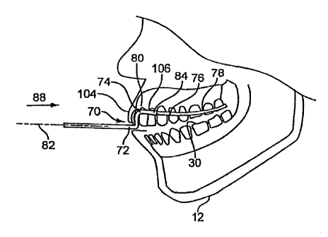
where
receptive fields, innervated by the superior laryngeal nerve (SLN) and the
pharyngeal branch of the glossopharyngeal nerve (GPNph), are believed to be
"reflexogenic" for swallowing (Mu and Sanders, 2000; Yoshida et al., 2000).
[0085] Air-pulse stimulation applied to the peri-tonsillar region of the
oropharynx in healthy controls evokes an irrepressible urge to swallow,
followed
by a frank swallow as verified by laryngeal and respiratory movement patterns
(Therurer et al., 2005), as shown in FIG. 24. Moreover, air-pulse stimulation
produces a significant increase in the frequency of saliva swallowing (FIGS.
24
and 25), with bilateral stimulation having a greater effect than unilateral.
These
findings were replicated and extended in to larger samples of healthy controls
(N-
16, Fortushnick et al; N=15, Girma et al.), and in a preliminary study of 2
patients
with dysphagia secondary to stroke demonstrates such results as shown in FIG.
26
(Theurer et al. 2005b).
[0086] In parallel with various behavioral studies, high-field functional
magnetic resonance imaging (fMRI) has been used to study the neural processing
of oropharyngeal air-pulse application. For example, SWAPT activates a
distributed brain network including the primary somatosensory cortex and the
thalamus, classical motor areas (primary motor cortex, supplementary motor
area,
cingulated motor areas and basal ganglia) and polymodal regions (including the
insula, inferior parietal cortex and frontal cortex) (Soros et al., 2008), as
shown in
FIG. 26. These cortical areas overlap regions previously implicated in oral
and
pharyngeal sensorimotor functions such as tongue movement, mastication, and
swallowing. Swallows that are produced at short latency after air-pulse
stimulation activate the same cortical network as habitual swallows,
suggesting
CA 02893780 2015-05-29
WO 2009/127947 PCT/1B2009/005252
that air-pulse application might be used to "drive" the cortical swallowing
network
as shown in FIG. 26.
[0087] The SWAPT air pulse trains are delivered to the oropharynx via a
mouthpiece 130 (see e.g., FIG. 23). One embodiment of the SWAPT mouthpiece
130 employed a custom silicone mouthpiece that fit over the lower dentition
(FIG. 23). In another embodiment, the SWAPT mouthpiece 100 sits within the
buccal cavity, between the teeth and cheek (FIG. 29). In this embodiment,
there is
no mouthpiece material between the upper and lower teeth based on patient
feedback indicating that inter-dental material was perceived as inhibiting
swallowing. The new mouthpiece is made of 1 mm thick dental resin (i.e.,
bleaching tray or mouth-guard material) that is vacuum-formed over a Dentoform
(a mock-up of the dentition and alveolar structures). Two lengths of fine-bore
polyethylene tubing (inner diameter: 0.045 inches; outer diameter: 0.062
inches)
are attached to the molded resin along the Dentoform margin between the teeth
and the gingiva, one on the right side of the dental form, and the other along
the
left side of the dental form. A second layer of resin is vacuum formed over
the
first layer, thereby enclosing the polyethylene tubing between the two sheets
of
dental resin. SWAPT efficacy with the mouthpiece of FIG. 29 was demonstrated
in a sample of 18 healthy geriatric participants as shown in FIG. 30 (Theurer
et al.,
2008).
[0088] The buccal mouthpiece 100 has several advantages. The patient is able
to maintain his/her upper and lower teeth 114, 116 in occlusion. This is
preferable
since kinematic studies of swallowing have shown that the upper and lower
teeth
are positioned along the occlusal plane during the pharyngeal stage of
swallowing.
The mouthpiece appears to have a relatively small impact on the resting
position
of the subject's mouth, tongue, oropharynx, and face. For example, the tongue
in
rest position does not make contact with the mouthpiece. Because the
mouthpiece
is thin, the subject is able.to achieve closure of the lips. The mouthpiece
does not
come in contact with pooled saliva in the sublingual region or along the
lingual
surfaces of the teeth. Being positioned within the upper or lower buccal
region,
26
CA 02893780 2015-05-29
WO 2009/127947 PCT/1B2009/005252
= the mouthpiece potentially allows the patient to ingest and swallow food
and drink
while the mouthpiece is in place.
[0089] Referring to FIGS. 1-5, another embodiment of a mouthpiece, referred
to as an oral cannula 2, for delivering a gas to the mouth of a user is shown.
The
oral cannula may include a pair of flexible tubes 4, 6 configured to be
positioned
on opposite sides of the face of a user. Of course, it should be understood
that the
oral cannula may include only a single tube disposed on one side of the user's
face. The oral cannula may also be configured with two tubes, but with gas
being
delivered through only one of the tubes. in some desired treatment modalities.
The
flexible tubes 4, 6 may be made of thermoformed tubing, which can be formed
into a particular shape and configuration, but which has some flexibility and
ability to conform to the face and mouth of the user. In one suitable
embodiment,
the flexible tube is made of polyurethane, polyethylene, PVC, other suitable
and
=biocompatible materials, and/or combinations thereof. The tubes may have a
1/8th
inch outer diameter and a 1/16th inch inner diameter forming a lumen. Of
course,
other size tubes may also be suitable, and the cross-sectional shape may be
circular, or configured in other geometrical shapes. The tubes may be clear or
transparent, translucent, coloured or opaque, and/or various combinations
thereof,
with the visual characteristics varying along the length of the tube for
example so
as to provide one or more windows. Each tube may also be formed with a
plurality of lumens, or channels, to allow for additional features such as
light,
sensors, fluid delivery, etc., including for example and without limitation
the
delivery of an aerosolized liquid 130 through a port 126, shown for example in
FIG. 20. In such embodiments, the lumens may run parallel to each other, and
include for example and without limitation a first inner lumen and a second
exterior lumen formed around the inner lumen, or alternatively two or more
lumens running side by side. Of course, the plurality may include more than
two
lumens.
[0090] In one embodiment, shown in FIG. 13, a wire 8 runs along a length of
at least a portion of the flexible tubing 4, 6. The wire provides further
shape
27
CA 02893780 2015-05-29
WO 2009/127947 PCT/1B2009/005252
memory to the flexible tubing. The wire may be co-extruded with the tube, or
= may be connected to the tubing by molding, welding, adhesives and the
like, or
combinations thereof.
[0091] Referring to FIGS. 1-5, the flexible tube 4,6 may be made of,
impregnated with, or coated with a flavored material, including without
limitation
fruit (e.g., lemon), menthol or mint flavors, which may be pleasing to the
user and
which may facilitate swallowing. The tube may also be made of, impregnated
= with, or coated with, an antistatic material, or alternatively a
conductive material.
Antistatic materials have a surface resistivity of between about 10E10 ohm/sq
and
about 10E 12 ohm/sq. Static dissipative materials have a surface resistivity
of
between about 10E6 ohm/sq. and about 10E12 ohm/sq. Conductive materials have
a surface resistivity of between about 10E1 ohm/sq and about 10E6 ohm/sq.
Metals typically have a surface resistivity of between about 10E-1 to about
10E-5
ohm/sq. Surface resistivity as set forth herein is measured pursuant to ASTM
test
D257. The tubing may also be made of, or coated with, an antibacterial
material.
For example, silver impregnation may provide antibacterial properties.
[0092] Each flexible tube 4, 6 includes an inlet portion 10, which is
preferably
elongated and may extend from the neck region to the ear of the user. The
inlet
portion has an inlet end portion 12 connected to an adapter (e.g., Y adapter)
14,
with the adapter having a feed tube 16 connected to an opposite end thereof. A
slideable connector 20, configured in one embodiment as a sleeve, is disposed
over and slidably receives the inlet portions 10 of the tubes. The connector
20
may be moved back and forth along a portion of the lengths of the inlet
portions
10 of the tubes so as to lengthen the end portion 12, and thereby secure the
tubes
under the chin of the user, or to shorten the end portion 12, and thereby
loosen the
tubes for comfort or removal.
[0093] The feed tube 16 is configured to connect to a gas source 22, for
example and without limitation by way of a quick connect 18 having a
releasably
component, such as a detent. The term "gas" refers to and includes air,
oxygen,
and/or any other type of gaseous substance suitable for breathing by humans,
28
CA 02893780 2015-05-29
WO 2009/127947 PCT/1B2009/005252
including for example and without limitation flelzox 3he gas may also include
various medicaments entrained therein for further treatment of the user, for
example various medicaments applied via an aerosol such as antibiotics for
pulmonary infections or COPD medications. The gas source is configured to emit
pulses of gas, with the volume, temperature, pressure, duration and/or
frequency
being controlled by a central processor and control system. The gas source can
alternatively be configured to emit a continuous source of gas. The system can
also be configured to sense the respiratory cycle of the user, such that gas
is
delivered only during a certain portion of the cycle, e.g., during exhalation.
Various exemplary control systems are shown and disclosed in US Pub. No.
2006/0282010A1, entitled Oral Device, the entire disclosure of which is hereby
incorporated herein by reference.
[0094] Referring to FIGS. 1-5, the pair of tubes 4,6 are a mirror image of
each
other, or can be folded one onto the other, along a longitudinal axis 24. As
shown
in FIGS. 1 and 2, various portions of the tubes may be formed or positioned
within
a plane 26, although during use, as shown in FIGS. 4 and 5, the tubes 4, 6
conform
to the face 28 of the user and is self supported on the face and in the mouth
30,
meaning the user and/or care giver are not required to hold or position the
tubes
with their hands, lips, tongue, teeth and/or other. devices.
[0100] The tubes 4,6 each have a curved portion 32 forming an ear loop
connected to the inlet portion 10. In one embodiment, the ear loop 32 may be
encapsulated, or covered with a padding material 40, such as foam, which
provides greater comfort to the user. Of course, it should be understood that
other
portions of the tube, such as the portion 42 running along the face of the
user, may
also be covered or secured to an interfacing material, such as a padding, to
improve comfort.
[0101] Another curved portion 34 forms a lip bend. The curved portion 34 is
connected to the curved portion 32 with an elongated portion 42 that runs
along
the face or cheek of the user as shown in FIGS. 4 and 5. As shown in FIGS. 1-
3,
the curved portion 34 has a curvature that is less than the curvature of the
curved
29
CA 02893780 2015-05-29
WO 2009/127947 PCT/1B2009/005252
=
portion 32, meaning in this embodiment, the radius of the curved portion 32 is
greater than the radius of the second curved portion 34. In one suitable
embodiment, the curvature of the curved portion 34 has an inner radius of
about
.25 inches. It should be understood that the curvatures may be other than semi-
circular, such as quarter circular, and may for example be curvilinear, or
polygonal
(i.e., formed from a plurality of discrete linear segments). The term
"curvature"
refers to the tube having a first portion defining a first vector 44 and a
second
portion defining a second vector 46, wherein the vectors are co-planar but not
the
same (meaning they may have different angles or orientations (e.g., parallel
but
directed in opposite directions)). It should be understood that a curved
portion
may have multiple curvatures, for example having a curvature in one plane and
another curvature in another plane. For example, the curved portion 34, or lip
bend, has a plurality of curvatures, including a first curvature in a plane 26
as
shown in FIGS. 2 and 3, and a second curvature of a portion thereof as the
curved
portion 34 transitions to an outlet portion 36 having a curvature in a plane
48
substantially perpendicular to the plane 26. It should be understood that the
curvatures may be formed in multiple planes not perpendicular or parallel to
each
other. In the embodiment of FIGS. 1-3, the curved portions 32,34 open in
opposite first and second directions 50, 52.
[0102] The outlet portion 42 extends from the curved portion 32 and terminates
in an end portion 38 having a gas exit port 54. The outlet portion 42 has a
curvature defined by first and second vectors 44, 46 forming angles f3 of 30
relative to the plane 26. In one embodiment, the length (L1) of the outlet
portion
is about 1.6 inches ( 2.5mm, e.g., 1.575 inches), or 1.760 inches ( .25mm)
from
the inner surface of the curved portion 32 to the terminal end of the end
portion
38, with the end portion extending below the first plane. The end portion 38
may
also be formed as a curved portion, having a curvature in the first plane 26
that
may be 0.75 inches and form a vector 56 at an angle a of about 20 with the
vertical plane 48 in which the curved portion 36 of the outlet portion lies.
= 30
CA 02893780 2015-05-29
vvp 2009/127947 PCT/1B2009/005252
[0103] The outlet portion 36, as shown in FIG. 11, is curved such that it
extends into the user's mouth 30 and is disposed between the side of a row of
upper teeth 58 of the user and the interior surface 60 of the user's cheek. Of
course, it should be understood that the configuration and shape can be
altered to
accommodate placement along the side of the lower teeth or along the occlusal
plane: The end portion 38, or curved portion, may be directed laterally
inwardly at
a targeted region of the rear of the user's mouth 30 and throat. The end
portion is
configured with the gas exit port 54. In this way, no portion of the tube is
disposed between the user's upper and lower teeth. As such, the tube does not
interfere with normal speech, eating, drinking swallowing, etc., and does not
have
to be held in place over or between the user's teeth. In one embodiment, each
of
the inlet portions, ear loop, lip bend and outlet portion may be integrally
formed
from a single piece of tubing.
[0104] Referring to FIG. 10, an alternative embodiment of an oral cannula
includes a manifold 62 that extends across the back of the user's mouth behind
the
rearmost teeth of the user and connects the tubes 4, 6 on opposite sides of
the
mouth. The manifold includes one or more gas exit ports 64 formed therein, for
example thought a side wall of the manifold, rather through an end portion or
lumen. In one embodiment, the manifold may be integrally formed with the other
portions of the tubes, such that a single loop of tubing forms and defines the
cannula.
[0105] Referring to FIGS. 6-9 and 12, another embodiment of an oral cannula
for delivering a gas to the mouth of a user includes a housing 70 comprising
an
inlet portion 72, a riser portion 74 extending upwardly from the inlet portion
and a
curved outlet portion 76. The housing may be a molded component, formed for
example and without limitation, from a flexible material such as silicone or
an
elastomeria material. The inlet, riser and outlet portions are shaped and
configured to conform to, and match the contours of, the user's mouth and
lips.
The housing is further configured to hold and shape one or more flexible tubes
78,
80, such that the tubing is properly positioned in the user's mouth without
31
CA 02893780 2015-05-29
wp 2009/127947 PCT/1B2009/005252
interfering with the various oral functions of the user. As such, the housing
directs
the tubing to the sides of the user's mouth between the outer sides of the
user's
Upper teeth 58 and the interior surface of the cheek 60.
[0106] The housing 70 may be made of a single piece, for example with one or
two channels that receive the tubing. For example and without limitation, the
= tubing may be snap-fitted into the channels. In other embodiments, the
tubing is
threaded through openings formed in the tube. In yet other embodiments, the
housing includes first and second housing components. One or more tubes,
=
depending on the application, are disposed between the two housing components,
with the housing components being secured to each other, for example and
without limitation, by snap fit, welding, mechanical fasteners, adhesives,
bonding,
= or various combinations thereof. The housing may be molded, for example
injection molded.
[0107] As shown in FIGS. 6-9, the inlet portion 72 may have a pair of
channels, with the tubes entering the channels in a first plane, for example
and
without limitation a horizontal plane 82. The riser portion 74 extends
upwardly
and rearwardly from the inlet portion. The outlet portion 76 has a pair of
branches
84 that extend laterally outwardly and rearwardly from the riser portion. The
outlet portion is curved, and has a first curvature when viewing the curved
outlet
portion from a first direction 86 and a second curvature when viewing the
curved
outlet portion from a second direction 88, wherein the first and second
directions
are non-parallel. In one embodiment, the first and second directions are
substantially perpendicular. The first curvature 90 matches the curvature of
the
front teeth of the user and directs the tubes laterally and rearwardly along
the
teeth. The second curvature 92 forms a dip that provides clearance for the
upper
labial frenum.
[0108] The flexible tubes 78, 80 are coupled to the housing 70 and extend
through the inlet portion 72, the riser portion 74 and out of respective ones
of the
branches 84 of the outlet portion. Each flexible tube has an outlet portion
with an
end portion extending from the outlet portion 76 of the housing. In one
32
CA 02893780 2015-05-29
WO 2009/127947 PCT/1B2009/005252
embodiment, the end portion 94 has a curvature that substantially follows and
matches the sides of the row of teeth of the user. The end portion has a gas
exit
port 9 positioned downstream of the outlet portion of said housing. It should
be
understood that in one embodiment, only a single tube is secured through the
housing. In another embodiment, the end portions may be joined by a manifold
62
as shown in FIG. 10.
[0109] In any of the embodiments, the oral carmula is configured with
orientation indicia 96, which provides information to the user and/or care
giver
about the orientation and positioning of the carmula. For example and without
limitation, in the embodiment of FIGS. 1-5, indicia can be positioned on the
adapter 14 and/or slide connector 20 to indicate which surface thereof is the
front
or back. Likewise, in the embodiment of FIGS. 6-9, indicia can be positioned
on
the housing 70.
[0110] Alternatively, in the embodiment of FIGS. 6-9, the shape of the housing
70 provides a visual indicator, or indicia, about the orientation of the
device. In
the various embodiments, for example and without limitation, an "R" or "B" can
be provided on the back of the connector 20 or other component to indicate
"Rear"
or "Back," an "F" can be provided to indicate "Front," and/or an "L" or "R"
can
be provided on the sides, front or back to indicate "Left" and "Right"
respectively.
Tactile indicia, in the form of Braille characters or raised
letters/embossments, can
be provided for users and/or care givers with poor sight or for use in poor
lighting
conditions. Other suitable indicia include without limitation various text
(e.g.,
"Left" and/or "Right"), arrows, various directional indicia and/or
combinations
thereof. With the use of such indicia, the user and/or care giver can properly
locate the oral cannula on the face, and in the mouth, of the user. The
adaptor 14
may also be shaped, for example with an angled portion receiving the feed tube
16, so as to direct the feed tube away from the user and provide indicia to
the user
' about the orientation, similar to the shape of the housing 70.
Alternatively, a tab,
tape or other marker may be provided on the right and left tubes to identify
them
as such.
33
CA 02893780 2015-05-29
WO 2009/127947 PCT/1B2009/005252
= [0111] In operation, the user or care giver disposes the
flexible tube, and in
particular the outlet portion 36, between an outer side surface of a row of
teeth 58
(upper or lower) and an inner surface 60 of a cheek. In one embodiment, tubes
are
disposed on opposite sides of the mouth. The tubes are positioned such that
the
exit ports 54 are positioned in a rear region of the mouth and wherein no
portion of
the flexible tube is disposed between the upper and lower teeth of the user
such
that the upper and lower teeth can be closed against each other. In the
embodiment of the FIGS. 1-5, the ear loops 32 are disposed around the ears 100
of
the user, with the mouth/lip bend being positioned around/over the lip 102 and
the
outlet portion of the tube being positioned along the side of the teeth as
just
= described. The position of the connector 20 can then be adjusted to
further secure
the cannula to the user.
[0112] In the embodiment of FIGS. 6-9, the housing 70 is inserted between the
upper lip 104 and the front 106 of the upper row of teeth, with the tube(s)
being
positioned along the side of the teeth as described herein. As shown in FIG.
10,
either embodiment can be further configured with the manifold 62 extending
across the back of the mouth. Alternatively, in either embodiment of FIGS. 1-
9,
the outlet portion 36, or end portion 38 thereof, may be cut or trimmed such
that
the exit port 54 is positioned in the proper location in the mouth of the
user.
[0113] In any of the embodiments, the feed tube 16 is connected to the gas
source 22. A gas is then dispensed through the exit port(s) 54, 64, preferably
in
pulses of predetermine pressure, volume, duration and/or frequency, with the
user
then swallowing in response to the pulses of gas.
[0114] Any of the embodiments of the oral cannula can be made easily,
cheaply and quickly without having to make expensive, customized teeth molds.
Moreover, the device can be quickly and easily adjusted for a particular user
simply by trimming a portion of tubing if necessary. The flexible tube follows
the
natural contours of the user's face and mouth, yet has sufficient shape memory
to
ensure proper placement relative to the user's face, lips, mouth and teeth.
The
flexible tube is self-supporting in the preferred location in the user's
mouth, and is
= 34
CA 02893780 2015-05-29
WO 2009/127947 PCT/1B2009/005252
maintained in a proper position even with patients/users experiencing numbness
or
weakness of the lips, tongue or jaw. The device is not fitted over or between
the
user's upper and lower teeth, and does not have to be held in place by
specific jaw
positioning. In this way, the flexible tubing, which is disposed between the
user's
teeth and cheek, does not interfere with normal speech, eating, drinking
swallowing, etc., or with the gas pulse delivery and swallowing therapy.
[0115] Referring to FIG. 32, in one embodiment, the oral appliance, or part
thereof, is made of compliant tubing 141 that absorbs forces applied to its
inner
surface by the internal pressure of the substance being delivered through the
tubing. For example, pressurized gas, delivered through the oral appliance and
originating at its input end, will act on the compliant tubing with resulting
expansion and contraction of the tubing in direct relation to changes in
pressure of
the substance within the tubing. In one instance, a gas, controlled by a
pressure
regulator attached to the input end of the oral appliance, and delivered
through the
oral appliance, is applied in discrete pressure pulses, such that the
region(s) of
compliant tubing along the length of the oral appliance expand and contract,
for
example, within the buccal cavity. Depending upon the frequency of pressure
variations of the substance within the oral appliance, and associated
expansion and
compression of the compliant tubing, a kinetic or vibratory stimulus acts
directly
upon the surrounding oral tissues, exciting sensory receptors located in the
oral
=
mucosal lining.
[0116] In another embodiment, the substance that is delivered through the oral
appliance for the purpose of eliciting a physiological response by the human
or
animal user may excite sensory receptors of the oral or oropharyngeal regions
through a kinetic or a pressure effect. The substance being delivered via the
oral
appliance can be applied in discrete pulses, for example, air pulses. The air-
pulse
= trains so delivered produce a kinetic effect within the ambient surround
of the oral
appliance output end, and associated pressures acting upon the oral tissues,
exciting sensory receptors. This stimulus may be perceived by the user as
vibratory at some stimulus frequencies.
CA 02893780 2015-05-29
WO 2009/127947 PCT/1B2009/005252
In one embodiment shown in FIG. 33, the oral appliance provides a means of
positioning a stimulating electrode in the posterior region of the mouth of
the
human or animal user such that electrical stimulation can be applied to that
region.
In one embodiment, a bipolar surface skin stimulating electrode 142 is
positioned
immediately distal to the output end 124 of the oral appliance, and the
electrode
leads run within the oral appliance tubing within the buccal region of the
user 120,
continue within the tubing that exits the mouth between the user's lips 122
and
exits the tubing to connect to an electrical stimulation control unit 143.
With the
oral appliance in situ within the buccal region, the stimulating electrode
contacts
the soft tissues of the rear aspect of the mouth, providing a method for
applying
electrical stimulation to the oral cavity with the aim of evoking a
physiological
response in the user, such as a swallowing and/or salivation.
[0117] Although the present invention has been described with reference to
preferred embodiments, those skilled in the art will recognize that changes
may be
made in form and detail without departing from the spirit and scope of the
invention. As such, it is intended that the foregoing detailed description be
regarded as illustrative rather than limiting and that it is the appended
claims,
including all equivalents thereof, which are intended to define the scope of
the
invention.
36