Note: Descriptions are shown in the official language in which they were submitted.
CA 02901064 2017-01-13
ELECTRODE CONFIGURATION FOR A BIOSENSOR
BACKGROUND
Electrochemical biosensors are known in the art and have been used to
determine the
concentration of various analytes from biological samples, particularly from
blood. Various
configurations of electrochemical biosensors are described in U.S. Patent Nos.
5,413,690;
5,762,780; 5,798,031; 5,997,8171; 7,073,246; 7,195,805 and 7,473,398 and U.S.
Patent
Application Publication No. 2005/0016844.
As the number of patients suffering from diabetes and similar medical
conditions
increases, self-monitoring of blood glucose where the patient monitors his or
her blood
glucose level has become common practice. The purpose of monitoring the blood
glucose
level is to determine the blood glucose concentration level, and then to take
the requisite
corrective action based on whether the level is too high or too low in order
to bring the level
back within a normal or acceptable range. Failure to take corrective action
can result in
serious medical implications. Glucose monitoring is a fact of everyday life
for millions of
diabetic individuals. Additionally, failure to test blood glucose levels
properly and on a
regular basis can result in serious diabetes-related complications, including
cardiovascular
disease, kidney disease, nerve damage and/or blindness.
A number of biosensors utilize electrochemical analysis to determine the blood
glucose level by measuring a current that corresponds to an analyte
concentration. Such
biosensors may utilize a capillary chamber having an electrode substrate
providing a working
electrode area located in the capillary chamber. The current response of the
electrochemical
cell is directly proportional to the working electrode area. However,
variations in the
working electrode area may result from the manufacture and assembly of the
components of
the biosensor that define the capillary chamber and the position/location of
the working
electrode. Variations in the working electrode area in the capillary chamber
from one
biosensor to another are undesirable since such variations introduces
imprecision and/or
inaccuracy in the measured analyte concentration, which may in turn result in
an imprecise
and/or inaccurate measurement of the blood glucose level.
Therefore, biosensor arrangements which minimize variations in the working
electrode area associated with the manufacture of the biosensor are desirable.
Additionally,
1
CA 02901064 2017-01-13
maintaining a balanced ratio between the counter electrode area and the
working electrode
area in the capillary chamber is also desirable in order to increase the
precision and/or
accuracy of the biosensor.
2
CA 02901064 2017-01-13
SUMMARY
The present invention generally relates to a biosensor, and more specifically
relates to
an electrode configuration for a biosensor having a relatively
constant/balanced ratio between
.. the counter electrode area and the working electrode area, and having a
relatively low
variation in the working electrode area.
According to one form, a biosensor is provided which includes a capillary
chamber
having an inner boundary, a working electrode including an effective working
electrode
portion positioned within the capillary chamber, and a counter electrode
including an
effective counter electrode portion positioned within the capillary chamber.
The effective
working electrode portion defines an average working electrode width and has a
working
electrode neck defining a working electrode neck width that is reduced
relative to the average
working electrode width. The working electrode neck constitutes the sole
portion of the
working electrode that extends across the inner boundary and out of the
capillary chamber.
The effective counter electrode portion has a counter electrode neck that
constitutes the sole
portion of the counter electrode that extends across the inner boundary and
out of the
capillary chamber.
According to another form, a biosensor is provided which includes a capillary
chamber having an inner boundary, a working electrode including an effective
working
electrode portion positioned within the capillary chamber, and a counter
electrode including
an effective counter electrode portion positioned within the capillary
chamber. The effective
working electrode portion has a main body and a working electrode neck
extending
therefrom, with the working electrode neck constituting the sole portion of
the working
electrode that extends across the inner boundary and out of the capillary
chamber. The
effective counter electrode portion has a main body and a counter electrode
neck extending
therefrom, with the main body of the effective counter electrode portion
positioned generally
adjacent the main body of the effective working electrode portion, and with
the counter
electrode neck constituting the sole portion of the counter electrode that
extends across the
inner boundary and out of the capillary chamber.
According to another form, a biosensor is provided which includes a capillary
chamber having an inner boundary, a working electrode including an effective
working
electrode portion positioned within the capillary chamber, and a counter
electrode including
an effective counter electrode portion positioned within the capillary
chamber. The effective
3
CA 02901064 2017-01-13
working electrode portion defines an effective working electrode area exposed
to the
capillary chamber, with the effective working electrode portion having a
working electrode
neck that constitutes the sole portion of the working electrode that extends
out of the capillary
chamber. The effective counter electrode portion defines an effective counter
electrode area
exposed to the capillary chamber, with the effective counter electrode portion
having a
counter electrode neck that constitutes the sole portion of the counter
electrode that extends
out of the capillary chamber. The working electrode neck and the counter
electrode neck
each extend across a single inner side wall defining the inner boundary of the
capillary
chamber, and a ratio between the effective working electrode area and the
effective counter
electrode area is substantially constant as a position of the single inner
side wall is varied
along a length of the working electrode neck and the counter electrode neck.
Accordingly there is provided herein a biosensor, comprising:
a capillary chamber having an inner boundary;
a working electrode including an effective working electrode portion
positioned
within the capillary chamber, the effective working electrode portion defining
an average
working electrode width and having a working electrode neck defining a working
electrode
neck width that is reduced relative to the average working electrode width,
the working
electrode neck constituting the sole portion of the working electrode that
extends across the
inner boundary and out of the capillary chamber wherein the effective working
electrode
portion defines an effective working electrode area exposed to the capillary
chamber; and
a counter electrode including an effective counter electrode portion
positioned within
the capillary chamber, the effective counter electrode portion having a
counter electrode neck
defining a counter electrode neck width, the counter electrode neck
constituting the sole
portion of the counter electrode that extends across the inner boundary and
out of the
capillary chamber wherein the effective counter electrode portion defines an
effective counter
electrode area exposed to the capillary chamber,
wherein the effective working electrode area is different than the effective
counter
electrode area,
wherein the working electrode neck and the counter electrode neck each extend
across
a single inner side wall defining at least a portion of the inner boundary of
the capillary
chamber, and
wherein a ratio between the effective working electrode area and the effective
counter
electrode area is substantially constant as a position of the single inner
side wall of the
4
CA 02901064 2017-01-13
capillary chamber is varied along a length of the working electrode neck and
the counter
electrode neck.
In this embodiment, the working electrode neck width may be less than the
counter
electrode neck width. For example, the working electrode neck width may be no
more than
one-half of the counter electrode neck width.
In this embodiment, the working electrode neck width may be no more than 80%
of
the average working electrode width.
In this embodiment, the effective working electrode area may be less than the
effective counter electrode area.
In this embodiment, the working electrode neck width may be less than the
counter
electrode neck width.
In this embodiment, the effective working electrode portion may define an
effective
working electrode area exposed to the capillary chamber;
wherein the effective counter electrode portion defines an effective counter
electrode
area exposed to the capillary chamber; and
wherein a first ratio between the effective working electrode area and the
working
electrode neck width is substantially equal to a second ratio between the
effective counter
electrode area and the counter electrode neck width.
In the above embodiment, the effective working electrode area is less than the
effective counter electrode area.
In the above embodiment, the working electrode neck width is less than the
counter
electrode neck width.
In this embodiment, the single inner side wall defining the inner boundary of
the
capillary chamber comprises a lateral side wall extending across a width of
the biosensor.
In this embodiment, the biosensor may further comprise:
a support substrate including a first inner surface with the working and
counter
electrodes extending along the first inner surface; and
a spacer substrate including a first face and an opposite second face, the
spacer
substrate defining the inner boundary of the capillary chamber, the first face
of the spacer
substrate attached to the first inner surface of the support substrate.
In the above embodiment, the biosensor may further comprise a cover substrate
including a second inner surface attached to the second face of the spacer
substrate; and
wherein the capillary chamber is defined by overlapping portions of the first
inner
5
CA 02901064 2017-01-13
surface of the support substrate and the second inner surface of the cover
substrate in
combination with the inner boundary defined by the spacer substrate.
In the above embodiment, the spacer substrate may include a channel extending
therethrough from the first face to the second face, the channel defining the
inner boundary of
the capillary chamber.
In the above embodiment, the support substrate may have a length dimension
extending generally along a longitudinal axis and a width dimension extending
generally
along a transverse axis;
wherein the working electrode neck and the counter electrode neck each extend
in a
direction generally along the longitudinal axis.
In the above embodiment, the support substrate has a length dimension
extending
generally along a longitudinal axis and a width dimension extending generally
along a
transverse axis; and
wherein the working electrode neck and the counter electrode neck each extend
across
a single inner side wall defining the inner boundary of the capillary chamber,
the single inner
side wall extending generally along the transverse axis.
In the above embodiment, the effective working electrode portion may include a
main
body extending generally along the transverse axis and with the working
electrode neck
extending from the main body generally along the longitudinal axis.
In the above embodiment, the effective counter electrode portion may include a
loop
body extending peripherally about the main body of the effective working
electrode portion
and with the counter electrode neck extending from the loop body generally
along the
longitudinal axis.
Also provided herein is a biosensor comprising:
a capillary chamber having an inner boundary;
a working electrode including an effective working electrode portion
positioned
within the capillary chamber, the effective working electrode portion having a
main body and
a working electrode neck extending therefrom, the working electrode neck
constituting the
sole portion of the working electrode that extends across the inner boundary
and out of the
capillary chamber; and
a counter electrode including an effective counter electrode portion
positioned within
the capillary chamber, the effective counter electrode portion having a main
body and a
counter electrode neck extending therefrom, the main body positioned generally
adjacent the
6
CA 02901064 2017-01-13
main body of the effective working electrode portion, the counter electrode
neck constituting
the sole portion of the counter electrode that extends across the inner
boundary and out of the
capillary chamber,
wherein the effective working electrode portion defines an effective working
electrode area exposed to the capillary chamber,
wherein the effective counter electrode portion defines an effective counter
electrode
area exposed to the capillary chamber,
wherein the effective working electrode area is different than the effective
counter
electrode area,
wherein the working electrode neck and the counter electrode neck each extend
across
a single inner side wall defining at least a portion of the inner boundary of
the capillary
chamber, and
wherein a ratio between the effective working electrode area and the effective
counter
electrode area is substantially constant as a position of the single inner
side wall of the
capillary chamber is varied along a length of the working electrode neck and
the counter
electrode neck.
In the above embodiment, the main body of the effective counter electrode
portion
may have a loop configuration extending peripherally about the main body of
the effective
working electrode portion.
In the above embodiment, the main body of the effective working electrode
portion
and the working electrode neck may cooperate with one another to provide the
effective
working electrode portion with a T-shaped configuration.
In the above embodiment, the main body of the effective counter electrode
portion
may have a C-shaped configuration extending peripherally about the T-shaped
configuration
of the effective working electrode portion.
In the above embodiment, the effective working electrode portion positioned
within
the capillary chamber may define an average working electrode width, the
working electrode
neck defining a working electrode neck width that is reduced relative to the
average working
electrode width.
In the above embodiment, the working electrode neck width may be less than a
counter electrode neck width defined by the counter electrode neck.
7
CA 02901064 2017-01-13
In the above embodiment, the working electrode neck and the counter electrode
neck
may each extend across a single inner side wall defining the inner boundary of
the capillary
chamber.
In the above embodiment, the effective working electrode portion may define an
effective working electrode area exposed to the capillary chamber;
wherein the effective counter electrode portion defines an effective counter
electrode
area exposed to the capillary chamber; and
wherein a ratio between the effective working electrode area and the effective
counter
electrode area is substantially constant as a position of the single inner
side wall is varied
along a length of the working electrode neck and the counter electrode neck.
In the above embodiment, the effective working electrode portion may define an
effective working electrode area exposed to the capillary chamber;
wherein the effective counter electrode portion defines an effective counter
electrode
area exposed to the capillary chamber; and
wherein a first ratio between the effective working electrode area and a width
of the
working electrode neck is substantially equal to a second ratio between the
effective counter
electrode area and a width of the counter electrode neck.
In the above embodiment, the single inner side wall defining the inner
boundary of
the capillary chamber may comprise a lateral side wall extending across a
width of the
biosensor.
In the above embodiment, the biosensor may further comprise:
a support substrate including a first inner surface with the working and
counter
electrodes extending along the first inner surface, the support substrate
having a length
dimension extending generally along a longitudinal axis and a width dimension
extending
generally along a transverse axis; and
a spacer substrate including a first face and an opposite second face, the
spacer
substrate including one or more inner side walls defining the inner boundary
of the capillary
chamber, the first face of the spacer substrate attached to the first inner
surface of the support
substrate; and
wherein the working electrode neck and the counter electrode neck each extend
generally along the longitudinal axis and across a single inner side wall
defining the inner
boundary of the capillary chamber, the single inner side wall extending
generally along the
transverse axis.
8
CA 02901064 2017-01-13
Also provided herein is a biosensor comprising:
a capillary chamber having an inner boundary;
a working electrode including an effective working electrode portion
positioned
within the capillary chamber and defining an effective working electrode area
exposed to the
capillary chamber, the effective working electrode portion having a working
electrode neck
that constitutes the sole portion of the working electrode that extends out of
the capillary
chamber; and
a counter electrode including an effective counter electrode portion
positioned within
the capillary chamber and defining an effective counter electrode area exposed
to the
capillary chamber, the effective counter electrode portion having a counter
electrode neck
that constitutes the sole portion of the counter electrode that extends out of
the capillary
chamber, and
wherein the working electrode neck and the counter electrode neck each extend
across
a single inner side wall defining at least a portion of the inner boundary of
the capillary
chamber,
wherein the effective working electrode area is different than the effective
counter
electrode area, and
wherein a ratio between the effective working electrode area and the effective
counter
electrode area is substantially constant as a position of the single inner
side wall of the
capillary chamber is varied along a length of the working electrode neck and
the counter
electrode neck.
In the above embodiment, the effective working electrode area may be less than
the
effective counter electrode area.
In the above embodiment, the working electrode neck may define a working
electrode
neck width that extends across the single inner side wall defining the inner
boundary of the
capillary chamber;
wherein the counter electrode neck defines a counter electrode neck width that
extends across the single inner side wall defining the inner boundary of the
capillary
chamber; and
wherein a first ratio between the effective working electrode area and the
working
electrode neck width is substantially equal to a second ratio between the
effective counter
electrode area and the counter electrode neck width.
9
CA 02901064 2017-01-13
In the above embodiment, the working electrode neck width may be less than the
counter electrode neck width.
In the above embodiment, the effective working electrode area may be less than
the
effective counter electrode area.
In the above embodiment, the effective working electrode portion may define an
average working electrode width;
wherein the working electrode neck defines a working electrode neck width that
extends across the single inner side wall defining the inner boundary of the
capillary
chamber; and
wherein the working electrode neck width is reduced relative to the average
working
electrode width.
Further aspects, embodiments, forms, features, benefits, objects, and
advantages shall
become apparent from the detailed description and figures provided herewith.
CA 02901064 2017-01-13
BRIEF DESCRIPTION OF THE DRAWING FIGURES
FIG. 1 is a perspective view of a biosensor according to one form of the
present
invention.
FIG. 2 is a top plan view of the biosensor of FIG. 1.
FIG. 3 is a top plan view of the biosensor of FIG. 2 with the hydrophilic roof
removed.
FIG. 4 is a top plan view of the biosensor of FIG. 3 with the spacer substrate
removed.
FIG. 5a is cross-sectional view of a portion of the biosensor of FIG. 1, as
take along
view line 5a-5a of FIG. 2.
FIG. 5b is cross-sectional view of a portion of the biosensor of FIG. 1, as
take along
view line 5b-5b of FIG. 2.
FIG. 6 is an enlarged plan view of the distal end portion of the biosensor of
FIG. 1
illustrating the capillary chamber and the electrode configuration positioned
therein.
FIG. 7a is an enlarged plan view of the distal end portion of the biosensor of
FIG. 1
illustrating a nominal placement of the spacer substrate relative to the
support substrate and
the electrode arrangement.
FIG. 7b is an enlarged plan view of the distal end portion of the biosensor of
FIG. 1
illustrating a maximal placement of the spacer substrate relative to the
support substrate and
the electrode arrangement.
FIG. 7c is an enlarged plan view of the distal end portion of the biosensor of
FIG. 1
illustrating a minimal placement of the spacer substrate relative to the
support substrate and
the electrode arrangement.
FIG. 8a is an enlarged plan view of a distal end portion of a comparative
biosensor
illustrating a nominal placement of a spacer substrate relative to a support
substrate and an
electrode arrangement.
FIG. 8b is an enlarged plan view of the distal end portion of the comparative
biosensor illustrating a maximal placement of the spacer substrate relative to
the support
substrate and the electrode arrangement.
FIG. 8c is an enlarged plan view of the distal end portion of the comparative
biosensor illustrating a minimal placement of the spacer substrate relative to
the support
substrate and the electrode arrangement.
11
CA 02901064 2017-01-13
FIG. 9a is an enlarged plan view of a distal end portion of a second
comparative
biosensor illustrating a nominal placement of a spacer substrate relative to a
support substrate
and an electrode arrangement.
FIG. 9b is an enlarged plan view of the distal end portion of the second
comparative
biosensor illustrating a maximal placement of the spacer substrate relative to
the support
substrate and the electrode arrangement.
FIG. 9c is an enlarged plan view of the distal end portion of the second
comparative
biosensor illustrating a minimal placement of the spacer substrate relative to
the support
substrate and the electrode arrangement.
12
CA 02901064 2017-01-13
DETAILED DESCRIPTION OF THE ILLUSTRATED EMBODIMENTS
For purposes of promoting an understanding of the principles of the present
invention,
reference will now be made to the embodiments illustrated in the drawings and
specific
language will be used to describe the same. It will nevertheless be understood
that no
limitation of the scope of the invention is thereby intended, such alterations
and further
modifications in the illustrated device, and such further applications of the
principles of the
invention as illustrated herein being contemplated as would normally occur to
one skilled in
the art to which the invention relates.
The present invention generally relates to a biosensor, and more specifically
relates to
an electrode configuration for a biosensor having a relatively
constant/balanced ratio between
the counter electrode area and the working electrode area, as well as a
relatively low variation
in the working electrode area, to thereby improve the precision and/or
accuracy of current
measurements in the electrochemical analysis of an analyte positioned in a
capillary chamber
of the biosensor. Aspects and features of the biosensor are presented in FIGS.
1-7 which are
not necessarily drawn to scale and where like components in the various
drawing figures are
numbered alike.
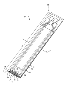
Referring to FIGS. 1-6, shown therein are various aspects and features of a
biosensor
10 according to one form of the present invention. In the illustrated
embodiment, the
biosensor 10 has a proximal end 10a and an opposite distal end 10b arranged
along a
longitudinal axis L, and generally includes an electrode support substrate 12,
an intermediate
spacer substrate 14 positioned on the support substrate 12, and a cover
substrate or
hydrophilic roof 16 positioned on the spacer substrate 14. The support
substrate 12, the
spacer substrate 14 and the cover substrate 16 cooperate with one another to
define a
capillary chamber or channel 18 having a sample inlet port 19 for receiving a
fluid sample
adjacent the distal end 10b of the biosensor 10. Additionally, the support
substrate 12
includes an electrical conductor arrangement 20 including a series of
electrodes 22, 24, 26a
and 26b that each include one or more electrode portions positioned within the
capillary
chamber 18, further details of which will be set forth below. Although the
illustrated
embodiment of the biosensor 10 includes three separate substrates 12, 14 and
16 that are
sandwiched together to form the capillary chamber 18, it should be understood
that other
embodiments are also contemplated including, for example, embodiments that do
not include
the cover substrate 16.
13
CA 02901064 2017-01-13
In the illustrated embodiment, the biosensor 10 is shown as having a
rectangular
configuration defining an overall length / extending generally along the
longitudinal axis L
between the proximal and distal ends 10a, 10b, and further defining an overall
width w
extending in a lateral direction generally along a transverse axis T. However,
it should be
understood that the biosensor 10 can be provided with other suitable shapes
and
configurations without departing from the principles of the present invention.
It should be
understood that the biosensor 10 can be any one of a substantial quantity of
biosensors
produced from rolls of material, sheets of material, or other material stock.
In one
embodiment, the selection of materials from which the biosensor 10 is
constructed includes a
stock sufficiently flexible for roll processing, but still rigid enough to
provide a
useful/sufficient stiffness to the biosensor 10. Additionally, the arrangement
and
configuration of the biosensor 10 and the manufacturing method associated with
forming the
biosensor 10 provides a relatively constant/balanced ratio between the counter
electrode area
and the working electrode area, as well as a relatively low variation in the
working electrode
area, to thereby improve the precision and/or accuracy of current measurements
in the
electrochemical analysis of an analyte positioned in the capillary chamber 18
of the biosensor
10, further details of which will be set forth below.
Referring collectively to FIGS. 4, 5a, 5b and 6, in the illustrated
embodiment, the
support substrate 12 has a rectangular configuration defining a length
dimension substantially
equal to the overall length / of the biosensor 10, and a width dimension
substantially equal to
the overall width w of the biosensor 10. The support substrate 12 includes a
bottom/lower
outer surface 30 defining an outer face of the biosensor 10, and a top/upper
inner surface 32
facing a direction opposite the outer surface 30. Additionally, the support
substrate 12
includes opposite first and second end surfaces or edges 34a, 34b extending
generally along
the transverse axis T (i.e., along the width dimension), and opposite first
and second side
surfaces or edges 36a, 36b extending generally along the longitudinal axis L
(i.e., along the
length dimension) between the end surfaces 34a, 34b. While the end surfaces
34a, 34b and
the side surfaces 36a, 36b of the support substrate 12 are illustrated to form
a generally
rectangular shape, as indicated above, it should be understood that the
biosensor 10, including
the support substrate 12, may form other shapes and configurations without
departing from
the principles of the present invention. In one specific embodiment, the
support substrate 12
is formed of a flexible polymer material including, for example, a polyester
or polyimide
14
CA 02901064 2017-01-13
such as polyethylene naphthalate (PEN). However, other suitable materials for
the support
substrate 12 are also contemplated.
As indicated above, the support substrate 12 includes an electrical conductor
arrangement or ablated electrode pattern 20 including a series of electrodes
22, 24, 26a and
.. 26b. The electrodes 22, 24, 26a and 26b are formed from an electrical
conductor 28
extending along the inner surface 32 of the support substrate 12. Non-limiting
examples of
materials suitable for the electrical conductor 28 include aluminum, carbon
(such as
graphite), cobalt, copper, gallium, gold, indium, iridium, iron, lead,
magnesium, mercury (as
an amalgam), nickel, niobium, osmium, palladium, platinum, rhenium, rhodium,
selenium,
silicon (such as highly doped polycrystalline silicon), silver, tantalum, tin,
titanium, tungsten,
uranium, vanadium, zinc, zirconium, mixtures thereof, and alloys, oxides, or
metallic
compounds of these or other elements. In one specific embodiment, the
individual electrodes
22, 24, 26a and 26b are isolated from one another via laser ablation or laser
scribing, and the
electrodes 22, 24, 26a and 26b may be created by removing select portions of
the electrical
conductor 28 from an area extending around/along the electrodes 22, 24, 26a
and 26b either
broadly, such as by broad field ablation, or minimally, such as by line
scribing. However, it
should be understood that other suitable techniques for forming the electrodes
22, 24, 26a and
26b are also contemplated as would occur to those of ordinary skill in the art
including, for
example, lamination, screen-printing, or photolithography.
In the illustrated embodiment, the electrode 22 is configured as a working
electrode,
the electrode 24 is configured as a reference or counter electrode, and the
electrodes 26a, 26b
are configured as sample sufficiency electrodes, with at least a portion of
each of the
electrodes 22, 24, 26a and 26b positioned within and exposed to the capillary
chamber 18.
Further aspects regarding the configuration and arrangement of the electrodes
22, 24, 26a and
.. 26b will be set forth in greater detail below. However, it should be
understood that other
suitable electrode configurations and arrangements are also contemplated as
falling within the
scope of the present invention.
Referring specifically to FIGS. 4 and 6, the working electrode 22 includes an
effective
working electrode portion 70 positioned within and exposed to the capillary
chamber 18, at
least one lead portion 72 extending away from the effective working electrode
portion 70 and
positioned outside of the capillary chamber 18, and at least one contact
portion 74 extending
from the lead portion 72 and positioned near the proximal end 10a of the
biosensor 10. The
counter electrode 24 includes an effective counter electrode portion 80
positioned within and
CA 02901064 2017-01-13
exposed to the capillary chamber 18, at least one lead portion 82 extending
from the effective
counter electrode portion 80 and positioned outside of the capillary chamber
18, and at least
one contact portion 84 extending from the lead portion 82 and positioned near
the proximal
end 10a of the biosensor 10. Additionally, the sample sufficiency electrodes
26a includes an
.. effective sample sufficiency electrode portion 90a positioned within and
exposed to the
capillary chamber 18, a lead portion 92a extending from the effective sample
sufficiency
electrode portion 90a and positioned outside of the capillary chamber 18, and
a contact
portion 94a extending from the lead portion 92a and positioned near the
proximal end 10a of
the biosensor 10, and the sample sufficiency electrodes 26b similarly includes
an effective
sample sufficiency electrode portion 90b positioned within and exposed to the
capillary
chamber 18, a lead portion 92b extending from the effective sample sufficiency
electrode
portion 90b and positioned outside of the capillary chamber 18, and a contact
portion 94b
extending from the lead portion 92b and positioned near the proximal end 10a
of the
biosensor 10.
In the illustrated embodiment, the leads 72, 82, 92a, 92b extend generally
along the
length / of the biosensor 10 from the effective electrode portions 70, 80,
90a, 90b positioned
within the capillary chamber 18 to the contacts 74, 84, 94a, 94b,
respectively. The contacts
74, 84, 94a, 94b provide an electrical connection with a test meter (not
shown) or another
device when the biosensor 10 is coupled thereto. It is contemplated that the
leads 72, 82, 92a,
92b extending from the effective electrode portions 70, 80, 90a, 90b can be
configured to
have any suitable shape, length or configuration, and may extend to any
suitable location on
the support substrate 12. It is further contemplated that the number and
configuration of the
effective electrode portions 70, 80, 90a, 90b, as well as the spacing between
the effective
electrode portions 70, 80, 90a, 90b, may be varied, and that the electrode
arrangement 20
may include any number of electrodes and other types/configurations of
electrodes other than
those specifically illustrated and described herein. For example, alternative
electrode
arrangements are illustrated and described in U.S. Publication No.
2011/0186428.
Referring collectively to FIGS. 3, 5a, 5b and 6, in the illustrated
embodiment, the
spacer substrate 14 has a rectangular configuration defining a length somewhat
less than the
length of the support substrate 12 and the overall length / of the biosensor
10 so as to expose
the electrode contacts 74, 84, 94a, 94b of the electrodes 22, 24, 26, 26b for
electrical
connection with a test meter (not shown). The spacer substrate 14 also
includes a
bottom/lower surface or face 40, and a top/upper surface or face 42 facing a
direction
16
CA 02901064 2017-01-13
opposite the bottom/lower face 40. Additionally, the spacer substrate 14
includes opposite
first and second end surfaces or edges 44a, 44b extending generally along the
transverse axis
T, and opposite first and second side surfaces or edges 46a, 46b extending
generally along the
longitudinal axis L and extending between the end surfaces 44a, 44b. While the
end surfaces
44a, 44b and the side surfaces 46a, 46b of spacer substrate 14 are illustrated
to form a
generally rectangular shape, as indicated above, it should be understood that
the biosensor 10,
including the spacer substrate 14, may form other shapes and configurations
without
departing from the principles of the present invention.
Referring specifically to FIG. 3, the spacer substrate 14 is sized and
configured to
overlay the support substrate 12, with the side surfaces 46a, 46b of the
spacer substrate 14
generally aligned with the side surfaces 36a, 36b of support substrate 12, and
with the end
surface 44b of the spacer substrate 14 generally aligned with the end surface
34b of support
substrate 12. However, the end surface 44a of the spacer substrate 14 is
axially offset/spaced
from the end surface 34a of support substrate 12 by a distance d so as to not
overlap the
electrode contacts 74, 84, 94a, 94b on the support substrate 12 to thereby
expose the electrode
contacts 74, 84, 94a, 94b for electrical connection with a test meter (not
shown).
Referring specifically to FIGS. 5a, 5b and 6, the spacer substrate 14 includes
a
generally rectangular-shaped notch or channel 50 extending entirely through
the thickness of
the spacer substrate 14 adjacent the end surface 44b. As will be discussed in
further detail
below, the channel 50 forms the inner boundary of the capillary chamber 18. In
the
illustrated embodiment, the channel 50 is defined by an inner edge or side
wall 52 facing the
capillary chamber 18. In the illustrated embodiment, the inner side wall 52
extends from the
end surface 44b at a location adjacent the side surface 46a and back to the
end surface 44b at
a location adjacent the side surface 46b to thereby provide the channel 50
with a generally
rectangular-shaped configuration. Additionally, in the illustrated embodiment,
the inner side
wall or edge 52 includes multiple edge portions or side walls 52a, 52b, 52c
that extend along
at least three sides of the capillary chamber 18 in a generally U-shaped
pattern to define the
inner outline or boundary of the capillary chamber 18, with the axial side
walls 52a, 52b
extending from the end surface 44b and generally along the longitudinal axis
L, and with the
lateral side wall 52c extending transversely between the axial side walls 52a,
52b. In the
illustrated embodiment, the axial side walls 52a, 52b are interconnected with
the lateral side
wall 52c via a pair of rounded corners 52d, 52e. The channel 50 further
defines an axially-
facing opening 54 adjacent the end surface 44b, which in turn defines the
sample inlet port 19
17
CA 02901064 2017-01-13
of the capillary chamber 18 adjacent the distal end 10b of the biosensor 10.
The axial side
walls 52a, 52b are separated or offset from one another to provide the
capillary chamber 18
with a capillary chamber width -wc, and the lateral side wall 52c is offset
from the end surface
44b to provide the capillary chamber 18 with a capillary chamber depth ck.
Additionally, the
spacer substrate 14 has a thickness measured from the bottom/lower face 40 to
the top/upper
face 42 to provide the capillary chamber 18 with a capillary chamber height h.
Although the channel 50 has been illustrated and described as having a
particular size,
shape and configuration, it should be understood that other suitable sizes,
shapes and
configurations are also contemplated. For example, in other embodiments, the
channel 50
may be provided with a non-rectangular configuration including, for example, a
hemi-ovular
configuration, a semi-circular configuration, a triangular configuration, or
other suitable
shapes and configurations. Additionally, various portions of the inner edge or
side wall 52 of
the channel 50 may be provided with a linear configuration, a curved or
rounded
configuration, a curvi-linear configuration and/or a polygonal configuration.
In other
embodiments, the opening 54 (and the corresponding sample inlet port 19) may
be provided
adjacent one of the side surfaces 46a, 46b of the spacer substrate 14, or
adjacent the
lower/bottom face 40 or the upper/top face 42 of the spacer substrate 14.
Furthermore, in the
illustrated embodiment, the spacer substrate 14 is configured as a single-
piece, unitary spacer
member. However, in other embodiments, the spacer substrate 14 can
alternatively be
comprised of a plurality of spacer members that are interconnected/integrated
with one
another to form the spacer substrate 14. In still other embodiments, the
spacer substrate 14
need not necessarily include a channel 50 extending therethrough to define the
inner
boundary of the capillary chamber 18. For example, in other embodiments, an
end surface or
edge (i.e., the lateral side wall 52c) of the spacer substrate 14 may provide
a single side wall
defining the inner boundary of the capillary chamber 18. In other words, the
spacer substrate
14 need not necessarily include the axial side walls 52a, 52b or the rounded
corners 52d, 52e,
but may instead provide a single side wall (i.e., the lateral side wall 52c)
defining the inner
boundary of the capillary chamber 18.
The spacer substrate 14 may formed from a wide variety of materials including
an
insulative material such as, for example, a flexible polymer such as an
adhesive coated
polyethylene terephthalate (PET)-polyester. A non-limiting example of a
suitable material
for the spacer substrate 14 includes a white PET film, with each of the
bottom/lower and
top/upper faces 40, 42 coated with a pressure-sensitive adhesive (PSA).
However, it should
18
CA 02901064 2017-01-13
be understood that other suitable materials and adhesives are also
contemplated. It should
also be understood that the bottom/lower face 40 of the spacer substrate 14
may be couple or
fixed to the upper surface 32 of the support substrate 12 via the adhesive
material. However,
other suitable techniques/methods for coupling or fixing the spacer substrate
14 to the support
substrate 12 are also contemplated including, for example, via heat or
ultrasonic welding. As
will be discussed in greater detail below, when the spacer substrate 14 is
coupled to the
support substrate 12, a portion of the top/upper surface of the support
substrate 12 overlaps
the capillary chamber 18 to thereby form a lower boundary of the capillary
chamber 18.
When spacer substrate 14 is coupled to the support substrate 12, the effective
electrode portions 70, 80, 90a, 90b of the electrode arrangement 20 are
positioned to lie
within the capillary chamber 18 which includes an inner boundary formed by the
inner edge
or side wall 52 of the spacer substrate 14 and the inwardly facing surfaces of
the support
substrate 12 and the cover substrate 16. As should be appreciated, any
variation in the
capillary chamber depth ck defined by the position of the lateral side wall
52c of the channel
50 relative to the end surface 44b may introduce variation in the effective
area of the effective
working electrode portion 70 located within the capillary chamber 18, thereby
resulting in
imprecision of the measured current value related to an analyte concentration.
However, as
will be discussed in detail below, the biosensor 10 is designed to minimize
the effects of
variations in the capillary chamber depth ck, as well as the effective area of
the effective
working electrode portion 70 exposed to the capillary chamber 18 when the
spacer substrate
14 is variably positioned relative to the support substrate 12.
Referring collectively to FIGS. 2, 5a and 5b, in the illustrated embodiment,
the cover
substrate 16 has a rectangular configuration defining a length generally equal
to the length of
the spacer substrate 14, but somewhat less than the overall length / of the
biosensor 10 so as
to maintain exposure of the electrode contacts 74, 84, 94a, 94b for electrical
connection with
a test meter (not shown). The cover substrate 16 includes a bottom/lower
surface 60 and a
top/upper surface 62 facing a direction opposite the bottom/lower surface 60
and defining an
outer surface of the biosensor 10. Additionally, the cover substrate 16
includes opposite first
and second end surfaces or edges 64a, 64b, and opposite first and second side
surfaces or
edges 66a, 66b extending generally along the longitudinal axis L and extending
between the
end surfaces 64a, 64b. While the end surfaces 64a, 64b and the side surfaces
66a, 66b of the
cover substrate 16 are illustrated to form a generally rectangular shape, as
indicated above, it
19
CA 02901064 2017-01-13
should be understood that the biosensor 10, including the cover substrate 16,
may form other
shapes and configurations without departing from the principles of the present
invention.
As shown in FIGS. 5a and 5b, the cover substrate 16 is sized and configured to
overlay the spacer substrate 14, with the side surfaces 66a, 66b of the cover
substrate 16
generally aligned with the side surfaces 46a, 46b of the spacer substrate 14,
and with the end
surfaces 64a, 64b of the cover substrate 16 generally aligned with the end
surfaces 44a, 44b
of the spacer substrate 14. The cover substrate 16 may be formed from a wide
variety of
materials including a flexible polymer material such as, for example, a
polyester or a
polyimide. One non-limiting example of a suitable polymer material is a
hydrophilic
polyester film. However, other suitable polymer materials or non-polymer
materials are also
contemplated. The bottom/lower surface 60 may be couple or fixed to the
top/upper face 42
of the spacer substrate 14 via the adhesive material associated with the
spacer substrate 14.
However, other suitable techniques/methods for coupling or fixing the cover
substrate 16 to
the spacer substrate 14 are also contemplated including, for example, via heat
or ultrasonic
welding. When the cover substrate 16 is coupled to the spacer substrate 14, a
portion of the
bottom/lower surface 60 of the cover substrate 16 overlaps the capillary
chamber 18 to
thereby form an upper boundary of the capillary chamber 18.
Additionally, in the illustrated embodiment, the cover substrate 16 defines a
series of
vent holes or apertures 68 extending through the cover substrate 16 from the
top/upper
surface 62 to the bottom/lower surface 60 and communicating with the capillary
chamber 18.
In one embodiment, the vent holes 68 are arranged in a linear manner adjacent
the lateral side
wall 52c of the channel 50 that forms an inner boundary of the capillary
chamber 18.
However, other suitable arrangements and positions of the vent holes 68 are
also
contemplated. As should be appreciated, the vent holes 68 serve as air outlets
to vent air
from the capillary chamber 18 as a fluid blood sample is drawn into the
capillary chamber 18
via capillary action. Although the vent holes 68 are illustrated and described
as being formed
through the cover substrate 16, it should be understood that other embodiments
are also
contemplated where the vent holes 68 may be formed through portions of the
support
substrate 12 and/or the spacer substrate 14. In still other embodiments, the
biosensor 10 need
not necessarily include vent holes 68. For example, in alternative
embodiments, other types
and configurations of capillary structures as would be appreciated by those of
skill in the art
may be incorporated into the biosensor 10 to replace the vent holes, thereby
eliminating the
need for vent holes.
CA 02901064 2017-01-13
Referring specifically to FIGS. 5a and 5b, the capillary chamber 18 is
bound/defined
on the top and bottom by the bottom/lower surface 60 of the cover substrate 16
and the
top/upper surface 32 of the support substrate 12, and is also bound/defined by
the inner side
wall 52 of the spacer substrate 14 to thereby define an inner boundary of the
capillary
chamber 18. The open end 54 of the channel 50 adjacent the end surfaces 44b of
the spacer
substrate 14 defines the sample inlet port 19 that opens into the capillary
chamber 18 to
permit entry of a fluid blood sample into the capillary chamber 18. Referring
to FIG. 6, the
effective electrode portions 70, 80, 90a, 90b are positioned within and in
fluid
communication with the capillary chamber 18. It is further contemplated that
electrochemical reagents can be positioned within the capillary chamber 18 at
or near the
effective electrode portions 70, 80, 90a, 90b. The electrochemical reagents
provide
electrochemical probes for specific analytes. The choice of specific reagents
depends on the
specific analyte or analytes to be measured, the details of which are well
known to those of
ordinary skill in the art and therefore need not be discussed in detail
herein. An example of a
reagent that may be used in association with the biosensor 10 is a reagent for
measuring
glucose from a whole blood sample. However, it should be understood that other
suitable
reagents are also contemplated for use in association with the biosensor 10.
As indicated above, the working and counter electrodes 22, 24 have effective
electrode portions 70, 80, respectively, positioned within and exposed to the
capillary
chamber 18. Referring to FIG. 6, shown therein is an arrangement of the
effective working
electrode portion 70 and the effective counter electrode portion 80 according
to one
embodiment of the present invention. As will be discussed in greater detail
below, the
arrangement and configuration of the effective working and counter electrode
portions 70, 80
in combination with the configuration of other components of the biosensor 10
is designed:
1.) to maintain a balanced ratio between the effective working electrode area
Aw and the
effective counter electrode area A, positioned within and exposed to the
capillary chamber 18
as a result of imprecisions attributable to specification tolerances in the
manufacturing of the
biosensor 10; and 2.) to minimize variation in the absolute effective working
electrode area
Aw as a result of imprecisions attributable to specification tolerances in the
manufacturing of
the biosensor 10. Additionally, it should be understood that the electrode
features/characteristics attributable to satisfying these objectives allow for
the use of positive
and negative pulses to enable different types of measurement methods that
reduce variation in
the estimated blood glucose level, further details of which will be discussed
below.
21
CA 02901064 2017-01-13
In the illustrated embodiment, the effective working electrode portion 70
includes a
main body portion 76 and a single neck or leg portion 78 extending therefrom,
and the
effective counter electrode portion 80 includes a main body or loop portion 86
and a single
neck or leg portion 88 extending therefrom. In one embodiment, the main body
76 of the
effective working electrode portion 70 has a generally linear configuration
extending along
the capillary chamber width Iv, and arranged generally perpendicular to the
longitudinal axis
L of the biosensor 10, and the neck portion 78 extends from a mid-portion of
the main body
76 along the capillary chamber depth d and arranged generally along the
longitudinal axis L
to thereby provide the effective working electrode portion 70 with a generally
T-shaped
configuration having a pair of generally linear portions 76a, 76b extending in
opposite
directions relative to the neck portion 78. Additionally, in one embodiment,
the main body or
loop portion 86 of the effective counter electrode portion 80 has a generally
C-shaped or
looped configuration including generally linear portions 86a, 86b, 86c
extending along the
capillary chamber width Iv, and arranged generally perpendicular to the
longitudinal axis L of
the biosensor 10, a pair of rounded or arcuate portions 86d, 86e
interconnecting the far ends
of the linear portion 86a, 86b with the opposite ends of the linear portion
86c, and with the
neck portion 88 extending from the near end of the linear portion 86a along
the capillary
chamber depth ck and arranged generally parallel with the longitudinal axis L.
In the
illustrated embodiment, the main body or loop 86 of the effective counter
electrode portion
.. 80 is positioned generally adjacent the main body 76 of the effective
working electrode
portion 70. More specifically, the main body or loop 86 of the effective
counter electrode
portion 80 wraps or extends peripherally about the main body 76 of the
effective working
electrode portion 70, with the neck portions 78, 88 arranged generally
parallel with one
another adjacent the longitudinal axis L and centrally positioned within the
capillary chamber
18. As illustrated in FIG. 6, the corners defined by the outer edges of the
effective working
electrode portion 70 and the effective counter electrode portion 80 may be
rounded to
minimize electrical current concentrations that would otherwise be associated
with sharp or
non-rounded corners. As should be appreciated, such corners include those
formed between
the main body 76 and the neck 78, between the loop body 86 and the neck 88,
and at the free
ends of the main body 76 and the loop body 86. In one embodiment, the corners
may be
provided with a minimum radius of approximately 0.150 mm. Although specific
shapes,
configurations and arrangements of the effective working and counter electrode
portions 70,
80 have been illustrated and described herein, it should be understood that
other suitable
22
CA 02901064 2017-01-13
shapes, configurations and arrangements are also contemplated as falling
within the scope of
the present invention.
In the illustrated embodiment, the main body 76 of the effective working
electrode
portion 70 has a generally uniform width w4 along its length, and the neck 78
of the effective
working electrode portion 70 has a generally uniform width w2 along its length
that is
reduced/narrowed relative to the average width wi of the main body 76. In one
embodiment,
the width w2 of the neck 78 is no more than 80% of the average width of the
effective
working electrode portion 70. In another embodiment, the width w2 of the neck
78 is no
more than one-half the average width of the effective working electrode
portion 70.
However, other ratios between the width w2 of the working electrode neck 78
and the average
width of the effective working electrode portion 70 are also contemplated.
Additionally, the
main body 86 of the effective counter electrode portion 80 has a generally
uniform width w3
along its length, and the neck 88 of the effective counter electrode portion
80 has a generally
uniform width w4 along its length that may be sized greater than, equal to, or
less than the
.. generally uniform width w3 of the loop body 86. In the illustrated
embodiment, the width w2
of the working electrode neck 78 is less than the width w4 of the counter
electrode neck 88.
In one embodiment, the width w2 of the working electrode neck 78 is no more
than one-half
of the width w4 of the counter electrode neck 88. In another embodiment, the
width w2 of the
working electrode neck 78 is approximately 25-30% of the width 14/4 of the
counter electrode
neck 88. However, other ratios between the width w2 of the neck 78 and the
width w4 of the
neck 88 are also contemplated. Additionally, in the illustrated embodiment,
the spacing or
offset distance s between the portions of the effective working electrode 70
and the adjacent
portions of the effective counter electrode 80 is substantially uniform or
constant along the
entirety of the effective working and counter electrodes 70, 80. However,
other embodiments
are also contemplated where the spacing or offset distance between adjacent
portions of the
effective working and counter electrodes 70, 80 may vary in a non-uniform
manner.
As indicated above, the effective working electrode portion 70 is provided
with a
single axially-extending neck 78 and the effective counter electrode portion
80 is likewise
provided with a single axially-extending neck 88, with each of the necks 78,
88 extending
generally parallel with one another adjacent the longitudinal axis L and
centrally positioned
within the capillary chamber 18. As should be appreciated, each of the necks
78, 88 extends
across/intersects the inner edge or side wall 52 of the channel 50 that
defines the inner
boundary of the capillary chamber 18 at a single location, which in the
illustrated
23
CA 02901064 2017-01-13
embodiment constitutes the laterally-extending side wall 52c. As should also
be appreciated,
the axial location of the laterally-extending side wall 52c relative to the
effective working and
counter electrode portions 70, 80 may vary as a result of imprecisions
attributable to
tolerance specifications associated with the manufacturing process of the
biosensor 10. Such
imprecisions include but are not limited to variable axial placement of the
spacer substrate 14
relative to the support substrate 12 (and the effective working and counter
electrode portions
70, 80) along the longitudinal axis L, variations in the placement/size of the
lateral side wall
52c of the spacer substrate 14, variations in the placement of the effective
working and
counter electrode portions 70, 80 on the support substrate 12, and/or other
variations
associated with the manufacturing and assembly of the biosensor 10. However,
the
manufacturing specifications associated with the biosensor 10 are determined
to
dictate/ensure that the sole portions of the effective working and counter
electrode portions
70, 80 that extend across/intersect the laterally-extending side wall 52c (or
any portion of the
inner wall 52) of the capillary chamber 18 are the working and counter
electrode necks 78,
88. In other words, the manufacturing specifications dictate/ensure that the
laterally-
extending side wall 52c (or any other portion of the inner side wall 52) does
not
intersect/overlap/cover any portion of the main bodies 76, 86 of the effective
electrode
portions 70, 80, thereby ensuring that the main bodies 76, 86 of the effective
electrode
portions 70, 80 are positioned entirely within the capillary chamber 18 and
are not covered by
any portion of the spacer substrate 14.
Referring to FIGS. 7a-7c, shown therein are three exemplary axial placements
of the
spacer substrate 14 relative to the support substrate 12 (and the capillary
portions of the
working and counter electrodes 22, 24 positioned in the capillary chamber 18)
that may result
from imprecisions associated with the manufacturing and assembly process of
the biosensor
10. Specifically, FIG. 7a illustrates a nominal placement of the spacer
substrate 14 relative to
the support substrate 12 and the electrode arrangement 20 (i.e., the optimal
specification
tolerance limit on placement of the spacer substrate 14). In this nominal
placement of the
spacer substrate 12, each of the necks 78, 88 of the working and counter
capillary electrodes
22, 24 extend across/intersect the inner boundary of the capillary chamber 18
at a single
location (i.e., at the laterally-extending side wall 52c), and the main
electrode bodies 76, 86
are positioned entirely within the capillary chamber 18 with the laterally-
extending side wall
52c of the capillary chamber 18 spaced from the linear portions 86a, 86b of
the effective
counter electrode portion 80 at a nominal distance dn.. FIG. 7b illustrates a
maximal
24
CA 02901064 2017-01-13
placement of the spacer substrate 14 relative to the support substrate 12 and
the electrode
arrangement 20 (i.e., the upper specification tolerance limit on placement of
the spacer
substrate 14). In this maximal placement of the spacer substrate 12, the
electrode necks 78,
88 still extend across/intersect the inner boundary of the capillary chamber
18 at a single
location, and the main electrode bodies 76, 86 are still positioned entirely
within the capillary
chamber 18, but the laterally-extending side wall 52c of the capillary chamber
18 is spaced
from the linear portions 86a, 86b of the effective counter electrode portion
80 at a maximum
distance dm. FIG. 7c illustrates a minimal placement of the spacer substrate
14 relative to
the support substrate 12 and the electrode arrangement 20 (i.e., the lower
specification
.. tolerance limit on placement of the spacer substrate 14). In this minimal
placement of the
spacer substrate 12, the electrode necks 78, 88 still extend across/intersect
the inner boundary
of the capillary chamber 18 at a single location, and the main electrode
bodies 76, 86 are still
positioned entirely within the capillary chamber 18, but the laterally-
extending side wall 52c
of the capillary chamber 18 is spaced from the main electrode bodies 76, 86 at
a minimum
distance dmin, which in the illustrated embodiment constitutes a substantially
flush
arrangement of the laterally-extending side wall 52c relative to the linear
portions 86a, 86b of
the effective counter electrode portion 80.
As should be appreciated, since the area of the effective working electrode
portion 70
certain to be positioned within the capillary chamber 18 is significantly
greater than the
potential variance in the area of the neck 78 positioned within the capillary
chamber 18
resulting from acceptable tolerance levels associated with imprecisions in the
manufacturing
process, variations in the effective working electrode area A,õ, of the
effective working
electrode portion 70 exposed to the capillary chamber 18 is minimized, thereby
resulting in
improved measurement precision and/or accuracy of the biosensor 10. This
minimization of
the variation in the effective working electrode area A is primarily
attributable to the
reduced/narrowed width W2 of the neck 78 relative to the average width of the
effective
electrode portion 70 (i.e., minimization of the change in the area of the neck
78 along the
reduced/narrowed width w2 per unit length of the neck 78), and the assurance
that the sole
portion of the effective working electrode portion that extends
across/intersects the inner
boundary of capillary chamber 18 (i.e., the inner side wall 52) is the
reduced/narrowed width
14/2 of the single neck 78 that extends across/intersects the laterally-
extending side wall 52c.
As should also be appreciated, since the effective working and counter
electrode areas
(Aw, AO of the effective working and counter electrode portions 70, 80 certain
to be
CA 02901064 2017-01-13
positioned within the capillary chamber 18 is significantly greater than the
potential variance
in the areas of the necks 78, 88 positioned within the capillary chamber 18
resulting from
acceptable tolerance levels associated with imprecisions in the manufacturing
process of the
biosensor 10, a relatively constant/uniform ratio R between the effective
counter electrode
area A, and the effective working electrode area Aw exposed to the capillary
chamber 18 can
be maintained, which likewise results in improved measurement precision and/or
accuracy of
the biosensor 10.
The general meaning of the term "relatively constant" (when used in
association with
ratio R) is that for given uses of biosensors embodying the present invention,
maintaining
ratio R as uniform or otherwise absolutely constant is not necessary in
contexts in which a
certain amount of tolerance is acceptable. For example, in the context of the
biosensor 10
illustrated in FIGS. 7a-7c, if the minimal spacer position is adjusted such
that the inner
boundary of the capillary chamber overlaps the electrode necks 78, 88 at a
portion where one
or both of the necks 78, 88 begin to radius outwardly to the main body 76, 86
of each
electrode, respectively, then ratio R cannot be maintained uniformly.
Nevertheless, the
difference between ratio R at the nominal and maximal spacer positions and the
ratio R at the
minimal spacer position is relatively constant, and may still be acceptable
depending on the
degree of accuracy required for the particular use of the biosensor 10.
In order to maintain a relatively constant/uniform ratio R between the
effective
counter electrode area A, and the effective working electrode area Aw (i.e.,
R= AdAw) in
view of the acceptable tolerance levels associated with the manufacturing
process of the
biosensor 10, the following formula may be applied to provide parameters
regarding the
configuration/design of the working and counter electrodes: A,/w4=Aw/w2 (where
A, is the
effective counter electrode area, 14/4 is the width of the counter electrode
neck 88, Aw is the
effective working electrode area, and vv2 is the width of the working
electrode neck 78).
It should be understood that the effective working electrode area Aw and the
effective
counter electrode area A, are defined as the respective areas of the effective
working and
counter electrode portions 70, 80 exposed to the capillary chamber 18 and in
contact with a
fluid blood sample in the capillary chamber 18 when the capillary chamber 18
contains a
sufficient volume of the fluid blood sample to initiate a measurement
sequence. It should
also be understood that the widths vv2, -w4 of the working and counter
electrode necks 78, 88
are defined as the widths of the necks 78, 88 that are intersected/overlapped
by inner
boundary of the capillary chamber 18 (i.e., the laterally-extending side wall
52c).
26
CA 02901064 2017-01-13
In the illustrated embodiment, the sample sufficiency electrodes 26a, 26b are
configured as working and counter sample sufficiency electrodes, and are
configured as
substantially mirror images of one another relative to the longitudinal axis
L. However, it
should be understood that other embodiments are also contemplated wherein the
sample
sufficiency electrodes 26a, 26b are provided with different configurations. In
still other
embodiments, the sample sufficiency electrodes 26a, 26b are optional and are
not included in
the biosensor 10. In one embodiment, the sample sufficiency electrodes 26a
comprises a
working sample sufficiency electrode, and the sample sufficiency electrodes
26b comprises a
counter sample sufficiency electrode. However, a reverse configuration is also
contemplated.
As shown in the FIG. 6, the effective sample sufficiency electrode portions
90a, 90b of the
sample sufficiency electrodes 26a, 26b each have a generally triangular-shaped
cross section
that extends into the capillary chamber 18 from opposite sides of the
capillary chamber 18.
In the illustrated embodiment, the triangular-shaped effective electrode
portions 90a, 90b
each have a side surface 96a arranged at an obtuse angle relative to the
longitudinal axis L,
and an end surface 96b extending from the side surface 96a and arranged
generally
perpendicular to the longitudinal axis L. However, other suitable shapes and
configurations
of the capillary electrode portions 90a, 90b are also contemplated. As set
forth herein, the
sample sufficiency electrodes 26a, 26b are configured to detect when a
sufficient volume of a
liquid blood sample is received within the capillary chamber 18.
In use, a number of the biosensors 10 are typically packaged in a vial that
usually
includes a stopper or cap configured to seal the vial. It should be
appreciated, however, that
the biosensors may be packaged individually, or biosensors 10 can be folded
upon one
another, rolled in a coil, stacked in a cassette magazine, or packed in
blister packaging. In
another embodiment, the packaging may be formed as a card with removable
individual
segments comprised of biosensors, examples of which may be found in U.S.
Patent
Application Serial No. 12/198,197.
Many fluid sample types may be analyzed using the biosensor 10 discussed
herein.
For example, human body fluids such as, for example, whole blood, plasma,
sera, lymph,
bile, urine, semen, cerebrospinal fluid, spinal fluid, lacrimal fluid and
stool specimens as well
as other biological fluids readily apparent to one skilled in the art may be
measured. Fluid
preparations of tissues can also be assayed, along with foods, fermentation
products and
environmental substances, which potentially contain environmental
contaminants. Whole
blood may be assayed with the biosensor 10.
27
CA 02901064 2017-01-13
A user of the biosensor 10 initially places a finger having a blood collection
incision
or puncture adjacent/against the sample inlet port 19 to the capillary chamber
18. Capillary
forces pull a liquid blood sample from the incision or puncture through the
sample inlet port
19 and into the capillary chamber 18 and across the reagents and the electrode
arrangement
20 located in the capillary chamber 18. The liquid blood sample dissolves the
reagents and
engages the electrode arrangement 20 in the capillary chamber 18 where an
electrochemical
reaction takes place. In embodiments of the biosensor 10 including the sample
sufficiency
electrodes 26a, 26b, a signal is generated when the liquid blood sample in the
capillary
chamber 18 contacts the effective electrode portions 90a, 90b, thereby
indicating that a
sufficient volume of the liquid blood sample has been received in the
capillary chamber 18.
Sometime after the reaction has begun, a power source (e.g., a battery)
applies a potential
difference between the working and counter electrodes 22, 24. When the
potential difference
is applied, the amount of oxidized form of the mediator at the counter
electrode 24 and the
potential difference must be sufficient to cause electro-oxidation of the
reduced form of the
mediator at the surface of the working electrode 22. A current measuring meter
(not shown)
measures the current generated by the oxidation of the reduced form of the
mediator at the
surface of the working electrode 22.
As indicated above, the biosensor 10 disclosed herein is configured to
minimize
variations in the effective working electrode area Aõ exposed to the capillary
chamber 18,
and also maintains a relatively constant/uniform ratio R between the effective
counter
electrode area A, and the effective working electrode area A, exposed to the
capillary
chamber 18, thereby resulting in improvements to the precision and/or accuracy
of the
biosensor 10, and more particularly to improved precision and/or accuracy of
measured blood
glucose levels. It should be appreciated that such improvements to the
precision and/or
accuracy of the biosensor 10 resulting from the unique configuration and
features associated
with the working and counter electrodes 22, 24 and other structures/features
associated with
the biosensor 10 are particularly apparent in biosensor applications involving
the use of both
positive and negative pulsed signals between the working and counter
electrodes 22, 24 in the
sensing/measurement process to enable ascorbate detection and measurement of
blood
glucose levels. Such positive/negative pulsed signals may be realized via the
positive/negative pulses inherent in AC signals, and/or positive/negative
pulses that may stem
from the use of varied DC signals exhibiting positive and negative polarity.
However, it
28
CA 02901064 2017-01-13
should be understood that in other embodiments, the biosensor 10 need not
necessarily be
used in applications involving pulsed signals.
Referring to FIGS. 8a-8c, illustrated therein is a first comparative biosensor
100
including many of the same elements and features illustrated and described
above with regard
.. to the biosensor 10. For example, the comparative biosensor 100 has a
proximal end (not
shown) and an opposite distal end 100b arranged along a longitudinal axis L,
and generally
includes an electrode support substrate 112, an intermediate spacer substrate
114 positioned
on the support substrate 112, and a cover substrate or hydrophilic roof (not
shown) positioned
on the spacer substrate 114. The support substrate 112, the spacer substrate
114 and the
cover substrate cooperate with one another to define a capillary chamber or
channel 118
having a sample inlet port for receiving a fluid sample adjacent the distal
end 100b of the
biosensor 100. Additionally, the support substrate 112 includes an electrical
conductor
arrangement 120 including a series of electrodes 122, 124, 126a and 126b that
each include
one or more electrode portions positioned within the capillary chamber 118. In
the illustrated
embodiment, the electrode 122 is configured as a working electrode, the
electrode 124 is
configured as a reference or counter electrode, and the electrodes 126a, I26b
are configured
as sample sufficiency electrodes.
In the illustrated embodiment, the working electrode 122 includes an effective
working electrode portion exposed to the capillary chamber 118 having a main
body portion
176 and a single neck or leg portion 178 extending therefrom to thereby define
a generally T-
shaped configuration, and the counter electrode 124 includes an effective
counter electrode
portion having a main body or loop portion 186 positioned generally adjacent
the main body
176 of the effective working electrode portion, and more specifically defining
a generally C-
shaped or looped configuration that wraps or extends peripherally about the
main body 176 of
the effective working electrode portion and also having a single neck or leg
portion 188
extending from the main body 186. However, unlike the biosensor 10 illustrated
and
described above, the body portion 176 and the neck portion 178 of the working
electrode 122
have a substantially equal/uniform electrode width (i.e., the width of the
neck 178 is not
reduced relative to the main body 176). Additionally, the neck portion 178 of
the working
electrode 122 has a width that is substantially equal to the width of the neck
portion 188 of
the counter electrode 124. It should be appreciated that other than the
increased width of the
working electrode neck 178, the biosensor 100 is configured substantially
identical to the
biosensor illustrated and described above.
29
CA 02901064 2017-01-13
FIGS. 8a-8c illustrate three exemplary axial placements of the spacer
substrate 114
relative to the support substrate 112 (and relative to the effective portions
of the working and
counter electrodes 122, 124 positioned in the capillary chamber 118) that may
result from
imprecisions associated with the manufacturing and assembly process of the
biosensor 100.
.. It should be appreciated that the exemplary axial placements of the spacer
substrate 114
relative to the support substrate 112 illustrated in FIGS. 8a-8c correspond to
the exemplary
axial placements of the spacer substrate 14 relative to the support substrate
12 illustrated and
described above with regard to FIGS. 7a-7c.
Referring specifically to FIG. 8a, illustrated therein is a nominal placement
of the
spacer substrate 114 relative to the support substrate 112 and the electrode
arrangement 120.
In this nominal placement, the necks 178, 188 of the working and counter
capillary electrodes
122, 124 extend across/intersect the inner boundary of the capillary chamber
118 at a single
location (i.e., at the laterally-extending side wall 152c), and the main
electrode bodies 176,
186 are positioned entirely within the capillary chamber 118 with the
laterally-extending side
wall 152c of the capillary chamber 118 spaced from the linear portions 186a,
186b of the
effective counter electrode portion at a nominal distance dõõõ,. FIG. 8b
illustrates a maximal
placement of the spacer substrate 114 relative to the support substrate 112
and the electrode
arrangement 120 wherein the electrode necks 178, 188 extend across/intersect
the inner
boundary of the capillary chamber 118 at a single location, and the main
electrode bodies
176, 186 are positioned entirely within the capillary chamber 18, but the
laterally-extending
side wall 152c of the capillary chamber 118 is spaced from the linear portions
186a, 186b of
the effective counter electrode portion at a maximum distance cln,õ. FIG. 8c
illustrates a
minimal placement of the spacer substrate 114 relative to the support
substrate 112 and the
electrode arrangement 120 wherein the electrode necks 178, 188 extend
across/intersect the
inner boundary of the capillary chamber 118 at a single location, and the main
electrode
bodies 176, 186 are positioned entirely within the capillary chamber 118, but
the laterally-
extending side wall 152c of the capillary chamber 118 is spaced from the main
electrode
bodies 176, 186 at a minimum distance 4,, which in the illustrated embodiment
constitutes a
substantially flush arrangement of the laterally-extending side wall 152c
relative to the linear
portions 186a, 186b of the effective counter electrode portion.
Referring to FIGS. 9a-9c, illustrated therein is a second comparative
biosensor 200
including some of the same elements and features illustrated and described
above with regard
to the biosensor 10, but having a different configuration and layout relative
to the biosensor
CA 02901064 2017-01-13
10. In the illustrated embodiment, the comparative biosensor 200 has a
proximal end (not
shown) and an opposite distal end 200b arranged along a longitudinal axis L,
and generally
includes an electrode support substrate 212 and an intermediate spacer
substrate 214
positioned on the support substrate 212. The comparative biosensor 200 may
further include
a cover substrate or hydrophilic roof (not shown) positioned on the spacer
substrate 214. The
support substrate 212, the spacer substrate 214 and the cover substrate
cooperate with one
another to define a capillary chamber or channel 218 having a sample inlet
port for receiving
a fluid sample adjacent the distal end 200b of the biosensor 200.
Additionally, the support
substrate 212 includes an electrical conductor arrangement 220 including a
series of
electrodes 222, 224, 226a and 226b that each include one or more electrode
portions
positioned within the capillary chamber 218. In the illustrated embodiment,
the electrode 222
is configured as a working electrode, the electrode 224 is configured as a
reference or counter
electrode, and the electrodes 226a, 226b are configured as sample sufficiency
electrodes.
Unlike the biosensor 10 which includes a capillary chamber 18 having a
generally U-
shaped configuration (i.e., bound by a pair of axial side walls 52a, 52b and a
lateral side wall
52c which together define the inner boundary of the capillary chamber 18), the
capillary
chamber 218 of the biosensor 200 extends across the entire width of the
support substrate
212. In this embodiment, the distal edge of the spacer substrate 214 provides
a laterally-
extending side wall 252c defining an inner boundary of the capillary chamber
218. However,
other configurations are also possible, including embodiments similar to the
biosensor 10
where the capillary chamber defines a generally U-shaped configuration.
In the illustrated embodiment, the working electrode 222 includes an effective
working electrode portion exposed to the capillary chamber 218 and having a
main body
portion 276 and a single neck or leg portion 278 extending from an end of the
main body
portion 276 to thereby define a generally L-shaped electrode configuration.
Like the
biosensor 10 illustrated and described above, the effective working electrode
portion includes
a single neck portion that extends across/intersect the inner boundary of the
capillary
chamber 218 at a single location (i.e., at the laterally-extending side wall
252c).
Additionally, in the illustrated embodiment, the counter electrode 224
includes an effective
counter electrode portion exposed to the capillary chamber 218 and having a
first arm portion
286 defining a generally U-shaped configuration that extends or wraps about a
distal side of
the main body portion 276 of the effective working electrode portion, and a
second arm
portion 288 defining a generally linear configuration extending along a
proximal side of the
31
CA 02901064 2017-01-13
main body portion 276 and arranged generally parallel with the main body
portion 276. More
specifically, the first arm portion 286 and the second arm portion 288
together provide the
effective counter electrode portion with a looped configuration that wraps or
extends
peripherally about and encloses the main body portion 276 and the neck portion
278 of the
.. effective working electrode. However, unlike the biosensor 10 illustrated
and described
above, the effective counter electrode does not include a single neck portion
that extends
across/intersect the inner boundary of the capillary chamber 218 at a single
location (i.e., at
the laterally-extending side wall 252c). Instead, the end of the first arm
portion 286 and the
entire length of the second arm portion 288 extend across/intersect the inner
boundary of the
capillary chamber 218 at the laterally-extending side wall 252c.
FIGS. 9a-9c illustrate three exemplary axial placements of the spacer
substrate 214
relative to the support substrate 212 (and relative to the effective portions
of the working and
counter electrodes 222, 224 positioned in the capillary chamber 218) that may
result from
imprecisions associated with the manufacturing and assembly process of the
biosensor 200.
.. It should be appreciated that the exemplary axial placements of the spacer
substrate 214
relative to the support substrate 212 illustrated in FIGS. 9a-9c correspond to
the exemplary
axial placements of the spacer substrate 14 relative to the support substrate
12 illustrated and
described above with regard to FIGS. 7a-7c.
Referring specifically to FIG. 9a, illustrated therein is a nominal placement
of the
spacer substrate 214 relative to the support substrate 212 and the electrode
arrangement 220.
In this nominal placement, the neck 278 of the working electrode 222 extends
across/intersects the inner boundary of the capillary chamber 218 at a single
location (i.e., at
the laterally-extending side wall 252c). However, the counter electrode 224
extends
across/intersects the inner boundary of the capillary chamber 218 at multiple
locations. More
specifically, the first and second arm portions 286, 288 of the counter
electrode 224 each
extend across/intersect the inner boundary of the capillary chamber 218 at the
laterally-
extending side wall 252c. Additionally, while the main body portion 276 of the
working
electrode 222 is positioned entirely within the capillary chamber 218,
portions of the first and
second arm portions 286, 288 of the counter electrode 224 extend outside of
the capillary
.. chamber 218.
As illustrated in FIG. 9a, nominal placement of the spacer substrate 214
relative to the
support substrate 212 results in the laterally-extending side wall 252c of the
capillary
chamber 218 (i.e., the distal edge of the spacer substrate 214) being spaced
from the distal
32
CA 02901064 2017-01-13
side 288b of the second arm portion 288 of the counter electrode 224 at a
nominal distance
As illustrated in FIG. 9b, maximal placement of the spacer substrate 214
relative to the
support substrate 212 results in the laterally-extending side wall 252c of the
capillary
chamber 218 (i.e., the distal edge of the spacer substrate 214) being spaced
from the distal
.. side 288b of the second arm portion 288 at a maximum distance dm, which in
the illustrated
embodiment constitutes a substantially flush arrangement of the laterally-
extending side wall
252c relative to the proximal side 288a of the second arm portion 288 of the
counter electrode
224. As illustrated in FIG. 9c, minimal placement of the spacer substrate 214
relative to the
support substrate 212 results in the laterally-extending side wall 252c of the
capillary
chamber 218 (i.e., the distal edge of the spacer substrate 214) being spaced
from the distal
side 288b of the second arm portion 288 at a minimum distance dimn, which in
the illustrated
embodiment constitutes a substantially flush arrangement of the laterally-
extending side wall
252c relative to the distal side 288b of the second arm portion 288 of the
counter electrode
224.
For purposes of comparing the features, attributes and characteristics
associated with
the biosensor 10 relative to the comparative biosensors 100 and 200, Table A
sets forth data
associated with the biosensor 10 in the three exemplary configurations
illustrated in FIGS.
7a-7c (i.e., the nominal, maximum, minimum positions of the spacer substrate
14), Table B
sets forth data associated with the comparative biosensor 100 in the three
exemplary
configurations illustrated in FIGS. 8a-8c (i.e., the nominal, maximum, minimum
positions of
the spacer substrate 114), and Table C sets forth data associated with the
comparative
biosensor 200 in the three exemplary configurations illustrated in FIGS. 9a-9c
(i.e., the
nominal, maximum, minimum positions of the spacer substrate 214). It should be
understood
that the data set forth in Tables A, B and C is exemplary in nature, and does
not in any way
limit the scope of the present invention.
Referring to Table A below in combination with FIGS. 7a-7c, as indicated
above, the
biosensor 10 is designed and configured to minimize variations in the
effective working
electrode area A, of the working electrode 22 exposed to the capillary chamber
18 in view of
acceptable tolerance levels associated with manufacturing of the biosensor 10.
Additionally,
the biosensor 10 is also designed and configured to maintain a relatively
constant/uniform
ratio R between the effective counter electrode area Ac of the counter
electrode 24 exposed to
the capillary chamber 18 and the effective working electrode area A, of the
working
33
CA 02901064 2017-01-13
electrode 22 exposed to the capillary chamber 18 (i.e., R= AJA,) in view of
the acceptable
tolerance levels associated with manufacturing of the biosensor 10.
Effective Counter Effective Working % Variation of Area %
Variation of
Electrode Area Ac Electrode Area A w WE Area A w Ratio
Area Ratio R
(mm2) (mm2) _
(from nominal) R= Ac/A w (from nominal)
Nominal Spacer 0.68099 0.31751 2.145
Position (d.)
Maximum Spacer 0.69865 0.32576 +2.60% 2.145 0.00%
Position (d.)
Minimum Spacer 0.66332 0.30926 -2.60% 2.145 0.00%
Position (d,õ,õ)
Table A
With regard to minimizing variations in the effective working electrode area
A, of the
working electrode 22, the biosensor 10 is designed and configured to minimize
such
variations as the position/placement of the inner boundary of the capillary
chamber 18 (i.e.,
the inner side wall 52c) is varied between the nominal tolerance position
illustrated in FIG. 7a
and the maximum and minimum tolerance positions illustrated in FIGS. 7b and
7c,
respectively. As indicated above, since the effective working electrode area
A, positioned
within the capillary chamber 18 is significantly greater than the variance in
the area of the
neck 78 positioned within the capillary chamber 18 as the position of the
inner boundary of
the capillary chamber 18 is varied between the nominal, maximum and minimum
tolerance
positions, variance in the effective working electrode area A, is minimized.
This
minimization in the variation of the effective working electrode area A, is at
least partially
attributable to the reduced/narrowed width of the neck 78 relative to the
width of the main
body 76 of the effective working electrode (i.e., minimization of the change
in the area of the
neck 78 per unit length of the neck 78), as well as limiting the portion of
the working
electrode 22 that intersects the variable inner boundary (i.e., the inner side
wall 52c) of the
capillary chamber 18 to the reduced/narrowed width of the working electrode
neck 78.
As illustrated in Table A, in the exemplary embodiment of the biosensor 10,
the
variation of the effective working electrode area Aõ between the nominal and
the maximum
spacer positions is +2.60%, and the variation of the effective working
electrode area A,
between the nominal and the minimum spacer positions is -2.60%. Additionally,
the overall
variation of the effective working electrode area A, between the maximum and
minimum
spacer positions is +5.07%. In this exemplary embodiment, the width of the
working
electrode neck 78 is 0.050 mm, the width of the counter electrode neck 88 is
0.107 mm, the
34
CA 02901064 2017-01-13
width of the working electrode main body 76 is 0.100 mm, and the width of the
counter
electrode main body 86 is 0.100 mm. Additionally, the nominal distance dn. is
1.000 mm,
the maximum distance clina, is 1.165 mm, and the minimum distance dmin is
0.835 mm.
However, it should be understood that these values are exemplary in nature and
do not in any
way limit the scope of the present invention. As should be appreciated,
minimizing
variations in the effective working electrode area Aw as the
position/placement of the inner
boundary of the capillary chamber 18 is varied due to tolerance levels
associated with
manufacturing of the biosensor 10 results in perceptible improvements in the
precision and/or
accuracy of the biosensor 10, which in turn results in improved precision
and/or accuracy of
measured blood glucose levels.
With regard to maintaining a relatively constant/uniform ratio R between the
effective
counter electrode area Ac of the counter electrode 24 and the effective
working electrode area
Aw of the working electrode 22, the biosensor 10 is designed and configured to
substantially
maintain the area ratio Ras the position/placement of the inner boundary of
the capillary
chamber 18 (i.e., the inner side wall 52c) is varied between the nominal
tolerance position
illustrated in FIG. 7a and the maximum and minimum tolerance positions
illustrated in FIGS.
7b and 7c, respectively. As indicated above, the biosensor 10 and the
size/shape/configuration of the effective portions of the working and counter
electrodes 22,
24 are specifically designed such that the ratio R between the effective
electrode areas Ac, Aw
is substantially maintained as the position of the inner boundary of the
capillary chamber 18
is varied between the nominal, maximum and minimum tolerance positions.
Maintaining a
relatively constant/uniform ratio R is at least partially attributable to the
reduced/narrowed
width of the working electrode neck 78 relative to the width of the counter
electrode neck 88,
the reduced effective working electrode areas Aw relative to the effective
counter electrode
.. areas Ac, as well as limiting the portions of the working and counter
electrodes 22, 24 that
intersects the variable inner boundary of the capillary chamber 18 to the
working and counter
electrode necks 78, 88.
As illustrated in Table A, in one embodiment, the variation in the area ratio
R (i.e.,
Ac/Aw) between the nominal and the maximum spacer positions is 0.00%, and the
variation in
.. the area ratio R between the nominal and the minimum spacer positions is
also 0.00%.
Additionally, the overall variation in the area ratio R between the maximum
and minimum
spacer positions is likewise 0.00%. As discussed above, maintaining a
relatively
constant/uniform ratio R between the effective counter electrode area Ac and
the effective
CA 02901064 2017-01-13
working electrode area A, as the position/placement of the inner boundary of
the capillary
chamber 18 is varied due to tolerance levels associated with manufacturing of
the biosensor
results in perceptible improvements in the precision and/or accuracy of the
biosensor 10,
which in turn results in improved precision and/or accuracy of measured blood
glucose
5 levels. As should be appreciated, the illustrated embodiment of the
biosensor 10 exhibits a
perfectly constant/uniform ratio R between the effective counter electrode
area A, and the
effective working electrode area A, as the position/placement of the inner
boundary of the
capillary chamber 18 is varied due to tolerance levels associated with
manufacturing of the
biosensor 10. However, it should be appreciated that other embodiments of the
biosensor 10
10 are also contemplated where the biosensor exhibits a relatively
constant/uniform ratio R
between the effective counter electrode area A, and the effective working
electrode area A.
Referring to Table B below in combination with FIGS. 8a-8c, shown therein is
data
associated with the comparative biosensor 100. As indicated above, the
comparative
biosensor 100 is in many respects configured similar to the biosensor 10.
However, the neck
portion 178 of the working electrode 122 has a width that is equal to or
greater than the width
of the body portion 176 (i.e., the width of the neck 178 is not reduced
relative to the width of
the main body 176). Additionally, the neck portion 178 of the working
electrode 122 has a
width that is substantially equal to the width of the neck portion 188 of the
counter electrode
124.
As will become apparent below, compared to the biosensor 10, the particular
configuration of the working electrode 122 of the comparative biosensor 100 is
not
specifically designed to minimize variations in the effective working
electrode area A, as the
position/placement of the inner boundary of the capillary chamber 118 is
varied between the
tolerance positions illustrated in FIGS. 8a-8c. Additionally, compared to the
biosensor 10,
the particular configuration of the working and counter electrodes 122, 124 of
the
comparative biosensor 100 are not specifically designed to maintain a
relatively
constant/uniform ratio R between the effective counter electrode area A, and
the effective
working electrode area A, as the position/placement of the inner boundary of
the capillary
chamber 118 is varied between the tolerance positions illustrated in FIGS. 8a-
8c.
Effective Counter Effective Working % Variation of Area %
Variation of
Electrode Area Ac Electrode Area Aw WE Area A w Ratio
Area Ratio R
(mm2) (mm2)
(from nominal) R=Ac/Aw (from nominal)
Nominal Spacer 0.67459 0.33751 1.999
Position (d.)
36
CA 02901064 2017-01-13
Maximum Spacer 0.69109 0.35401 +4.89% 1.952 -2.35%
Position (d.)
Minimum Spacer 0.65808 0.32101 -4.89% 2.050 +2.55%
Position (d..)
Table B
As illustrated in Table B, in the exemplary embodiment of the biosensor 100,
the
variation of the effective working electrode area Aw between the nominal and
the maximum
spacer positions is +4.89 ')/0, and the variation of the effective working
electrode area Aw
between the nominal and the minimum spacer positions is -4.89%. Additionally,
the overall
variation of the effective working electrode area Aw between the maximum and
minimum
spacer positions is -9.32%. In this exemplary embodiment, the width of the
working
electrode neck 178 is 0.100 mm, the width of the counter electrode neck 188 is
0.100 mm, the
width of the working electrode main body 176 is 0.100 mm, and the width of the
counter
electrode main body 186 is 0.100 mm. Additionally, the nominal distance dn. is
1.000 mm,
the maximum distance dõ,õ is 1.165 mm, and the minimum distance d,n,, is 0.835
mm. As
should be appreciated, due to the increased width of the working electrode
neck 178 (relative
to the reduced width of the working electrode neck 78), the comparative
biosensor 100
exhibits greater variations in the effective working electrode area Aw
compared to the
biosensor 10 as the position/placement of the inner boundary of the capillary
chamber is
varied due to tolerance levels associated with manufacturing of the biosensor.
Accordingly,
the comparative biosensor 100 does not exhibit the same improvements in
precision and/or
accuracy as exhibited by the biosensor 10.
Additionally, the comparative biosensor 100 likewise does not maintain as
constant/uniform of a ratio R between the effective counter electrode area Ac
and the effective
working electrode area Aw compared to the biosensor 10 as the
position/placement of the
inner boundary of the capillary chamber is varied due to tolerance levels
associated with
manufacturing of the biosensor. Specifically, as illustrated in Table B, the
variation in the
area ratio R (i.e., Ac/Aw) between the nominal and the maximum spacer
positions is -2.35%,
and the variation in the area ratio R between the nominal and the minimum
spacer positions is
+2.55%. Additionally, the overall variation in the area ratio R between the
maximum and
minimum spacer positions is +5.02%. As should be appreciated, the comparative
biosensor
100 exhibits greater variations in the area ratio R between the effective
electrode areas Ac, Aw
compared to the biosensor 10 as the position/placement of the inner boundary
of the capillary
chamber is varied due to tolerance levels associated with manufacturing of the
biosensor.
37
CA 02901064 2017-01-13
=
Accordingly, it should be appreciated that the comparative biosensor 100 does
not exhibit the
same improvements in precision and/or accuracy as the biosensor 10.
Referring to Table C below in combination with FIGS. 9a-9c, shown therein is
data
associated with the comparative biosensor 200. As indicated above, the
comparative
biosensor 200 is in some respects configured similar to the biosensor 10.
However, the neck
portion 278 of the working electrode 222 has a width that is equal to or
greater than the width
of the body portion 276 (i.e., the width of the neck 278 is not reduced
relative to the width of
the main body 276). Additionally, the neck portion 278 of the working
electrode 222 has a
width that is substantially equal to the width of the first arm portion 286 of
the counter
electrode 224. Additionally, as indicated above, unlike the biosensor 10, the
effective
counter electrode portion of the counter electrode 224 does not include a
single "neck" that
extends across/intersects the inner boundary of the capillary chamber 218 at a
single location
(i.e., at the laterally-extending side wall 252c). Instead, the end of the
first arm portion 286
and the entire length of the second arm portion 288 each extend
across/intersect the inner
boundary of the capillary chamber 218 at the laterally-extending side wall
252c.
As will become apparent below, compared to the biosensor 10, the particular
configuration of the working electrode 222 and the counter electrode 224 of
the comparative
biosensor 200 are not specifically designed to minimize variations in the
effective working
electrode area Ay, and in the effective counter electrode area Ac as the
position/placement of
the inner boundary of the capillary chamber 218 is varied between the
tolerance positions
illustrated in FIGS. 9a-9c. Additionally, compared to the biosensor 10, the
particular
configuration of the working and counter electrodes 222, 224 of the
comparative biosensor
200 are not specifically designed to maintain a relatively constant/uniform
ratio R between
the effective counter electrode area Ac and the effective working electrode
area Aw as the
position/placement of the inner boundary of the capillary chamber 218 is
varied between the
tolerance positions illustrated in FIGS. 9a-9c.
Effective Counter Effective Working % Variation of Area %
Variation of
Electrode Area Ac Electrode Area A w WE Area A w Ratio Area
Ratio R
(mm2) (mm2) (from nominal) R=Ac/Aw (from
nominal)
Nominal Spacer 1.08544 0.45493 2.386
Position (dõõ,õ)
Maximum Spacer 1.49299 0.47143 +3.63 3.167 +32.73
Position (d.)
Minimum Spacer 0.67789 0.43843 -3.63 1.546 -35.21
Position (dmm)
Table C
38
CA 02901064 2017-01-13
As illustrated in Table C, in the exemplary embodiment of the biosensor 200,
the
variation of the effective working electrode area A, between the nominal and
the maximum
spacer positions is +3.63 %, and the variation of the effective working
electrode area A,
between the nominal and the minimum spacer positions is -3.63%. Additionally,
the overall
variation of the effective working electrode area A, between the maximum and
minimum
spacer positions is -7.00%. In this exemplary embodiment, the width of the
working
electrode neck 278 is 0.100 mm, the width of the working electrode main body
276 is 0.100
mm, the width of the counter electrode first arm portion 286 is 0.100 mm, and
the width of
the counter electrode second arm portion 288 is significantly greater than
0.100 mm.
Additionally, the nominal distance dim, can be 1.000 mm, the maximum distance
dmax can be
1.165 mm, and the minimum distance dmm can be 0.835 mm. As should be
appreciated, the
effective counter electrode portion of the counter electrode 224 does not
include a "neck"
extending across/intersecting the inner boundary of the capillary chamber 218,
as that term is
typically referred to by those having ordinary skill in the art. Instead, the
end of the first arm
portion 286 and the entire length of the second arm portion 288 each extend
across/intersect
the inner boundary of the capillary chamber 218 at the laterally-extending
side wall 252c.
As should also be appreciated, due to the increased width of the working
electrode
neck 278 (relative to the reduced width of the working electrode neck 78), the
comparative
biosensor 200 exhibits greater variations in the effective working electrode
area A, compared
to the biosensor 10 as the position/placement of the inner boundary of the
capillary chamber
is varied due to tolerance levels associated with manufacturing of the
biosensor.
Accordingly, the comparative biosensor 200 does not exhibit the same
improvements in
precision and/or accuracy as exhibited by the biosensor 10. As should be
further appreciated,
the comparative biosensor 200 likewise does not maintain as constant/uniform
of a ratio R
between the effective counter electrode area Ac and the effective working
electrode area A,
compared to the biosensor 10 as the position/placement of the inner boundary
of the capillary
chamber is varied due to tolerance levels associated with manufacturing of the
biosensor.
Specifically, as illustrated in Table C, the variation in the area ratio R
(i.e., Ac/A,) between
the nominal and the maximum spacer positions is +32.73, and the variation in
the area ratio R
between the nominal and the minimum spacer positions is -35.21%. Additionally,
the overall
variation in the area ratio R between the maximum and minimum spacer positions
is -
51.18%. As should be appreciated, the comparative biosensor 200 exhibits much
greater
variations in the area ratio R between the effective electrode areas Ac, A,
compared to the
39
CA 02901064 2017-01-13
biosensor 10 as the position/placement of the inner boundary of the capillary
chamber is
varied due to tolerance levels associated with manufacturing of the biosensor.
Accordingly,
it should be appreciated that the comparative biosensor 200 does not exhibit
the same
improvements in precision and/or accuracy as the biosensor 10.
While the invention has been illustrated and described in detail in the
drawings and
foregoing description, the same is to be considered as illustrative and not
restrictive in
character, it being understood that only certain embodiments have been shown
and described
and that all changes and modifications that come within the spirit of the
inventions are
desired to be protected.
It should be understood that while the use of words such as preferable,
preferably,
preferred or more preferred utilized in the description above indicate that
the feature so
described may be more desirable, it nonetheless may not be necessary and
embodiments
lacking the same may be contemplated as within the scope of the invention, the
scope being
defined by the claims that follow. In reading the claims, it is intended that
when words such
.. as "a," "an," "at least one," or "at least one portion" are used there is
no intention to limit the
claim to only one item unless specifically stated to the contrary in the
claim. When the
language "at least a portion" and/or "a portion" is used the item can include
a portion and/or
the entire item unless specifically stated to the contrary.