Note: Descriptions are shown in the official language in which they were submitted.
CA 02917868 2016-01-08
WO 2015/006335 PCT/US2014/045766
FIGURE EIGHT CLOSED LOOP COOLING SYSTEM FOR ELECTRONIC
DISPLAY
Inventors: William Dunn and Kevin O'Conner
Cross-Reference to Related Applications
[0001] This application claims priority to US Provisional Application No.
61/843,706
filed on July 8, 2013 which is herein incorporated by reference in its
entirety.
Technical Field
[0002] Embodiments generally relate to cooling systems for electronic
displays.
Background of the Art
[0003] Electronic displays are sometimes used in outdoor environments or other
areas where the surrounding temperatures may be high or there may be other
sources
of heat such as solar loading causing the temperatures within the display to
rise.
However, some portions of the display can be difficult to cool as simply
ingesting
ambient air into some portions of the display can introduce dust and
contaminates into
sensitive portions of the display, which can lead to premature failures.
Summary of the Exemplary Embodiments
[0004] Exemplary embodiments provide a figure eight closed loop circulating
gas path
which defines a center channel for the closed loop of circulating gas. A pair
of open
loop ambient air channels may be placed on opposite sides of the center
channel, in
order to remove heat from at least the center channel and the closed loop
circulating
1
CA 02917868 2016-01-08
WO 2015/006335 PCT/US2014/045766
gas. One or more open loop ambient air pathways may pass through the figure
eight
but do not allow the circulating gas and the ambient air to mix. In some
embodiments,
the open loop ambient air pathway travels along a rear surface of the
electronic display.
In some embodiments, the circulating gas pathways contain a front channel
placed in
front of the electronic display, a rear channel placed behind the electronic
display, and a
center channel placed between the front and rear channels. Pass-through
apertures
may be placed within the path of the circulating gas and/or the ambient air to
allow the
paths of the two gaseous matters to cross without allowing them to mix with
one
another.
[0005]The foregoing and other features and advantages of the present invention
will be
apparent from the following more detailed description of the particular
embodiments, as
illustrated in the accompanying drawings.
Brief Description of the Drawings
[0006] A better understanding of an exemplary embodiment will be obtained from
a
reading of the following detailed description and the accompanying drawings
wherein
identical reference characters refer to identical parts and in which:
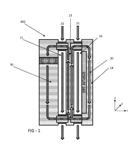
[0007] FIGURE 1 is a simplified illustration of an exemplary embodiment of the
figure
eight closed loop cooling system.
[0008] FIGURE 2 is a side rear perspective view showing the overall assembly
of the
display with the rear cover removed and indicating the section line 3-3.
[0009] FIGURE 3 is a perspective section view taken from the section line 3-3
and
indicating the locations for Detail 4 and Detail 5.
2
CA 02917868 2016-01-08
WO 2015/006335 PCT/US2014/045766
[0010] FIGURE 4 is a detailed perspective section view of Detail 4.
[0011] FIGURE 5 is a detailed perspective section view of Detail 5.
[0012] FIGURE 6 is a bottom rear perspective view showing the overall assembly
of
the display and indicating the section line 7-7.
[0013] FIGURE 7 is a perspective section view taken from the section line 7-7.
Detailed Description
[0014] The invention is described more fully hereinafter with reference to the
accompanying drawings, in which exemplary embodiments of the invention are
shown.
This invention may, however, be embodied in many different forms and should
not be
construed as limited to the exemplary embodiments set forth herein. Rather,
these
embodiments are provided so that this disclosure will be thorough and
complete, and
will fully convey the scope of the invention to those skilled in the art. In
the drawings, the
size and relative sizes of layers and regions may be exaggerated for clarity.
[0015] The terminology used herein is for the purpose of describing particular
embodiments only and is not intended to be limiting of the invention. As used
herein, the
singular forms "a", "an" and "the" are intended to include the plural forms as
well, unless
the context clearly indicates otherwise. It will be further understood that
the terms
"comprises" and/or "comprising," when used in this specification, specify the
presence of stated features, integers, steps, operations, elements, and/ or
components,
but do not preclude the presence or addition of one or more other features,
integers,
steps, operations, elements, components, and/or groups thereof.
3
CA 02917868 2016-01-08
WO 2015/006335 PCT/US2014/045766
[0016] Embodiments of the invention are described herein with reference to
illustrations that are schematic illustrations of idealized embodiments (and
intermediate
structures) of the invention. As such, variations from the shapes of the
illustrations as a
result, for example, of manufacturing techniques and/or tolerances, are to be
expected.
Thus, embodiments of the invention should not be construed as limited to the
particular
shapes of regions illustrated herein but are to include deviations in shapes
that result,
for example, from manufacturing.
[0017] Unless otherwise defined, all terms (including technical and scientific
terms)
used herein have the same meaning as commonly understood by one of ordinary
skill in
the art to which this invention belongs. It will be further understood that
terms, such as
those defined in commonly used dictionaries, should be interpreted as having a
meaning that is consistent with their meaning in the context of the relevant
art and will
not be interpreted in an idealized or overly formal sense unless expressly so
defined
herein.
[0018] FIGURE 1 is a simplified illustration of an exemplary embodiment of the
figure
eight closed loop cooling system 400. This exemplary embodiment contains a
plurality
of channels in the assembly. The front channel 18 is placed in front of the
display 160
and preferably allows closed loop circulating gas 20 to remove heat from the
front of the
display 160. The front open loop channel 16 is positioned behind the display
160 and
preferably allows open loop air 15 to pass behind the display 160, removing
heat at
least from the rear portion of the display 160 and the center channel 13. The
center
channel 13 is preferably positioned between the front open loop channel 16 and
the rear
open loop channel 11 and allows closed loop circulating gas 20 to cross paths
with itself
4
CA 02917868 2016-01-08
WO 2015/006335 PCT/US2014/045766
(creating the figure eight) and to cross paths with the open loop air 10 and
15 without
allowing the closed loop circulating gas and open loop air to mix.
[0019] The rear open loop channel 11 is preferably positioned immediately
adjacent
to the center channel 13, and allows open loop air 10 to flow through, thereby
removing
heat from the center channel 13 (and/or the closed loop circulating gas 13
contained
within) and the rear channel 30. The rear channel 30 is positioned near the
rear of the
display and may contain various electronic components 35 for operating the
overall
display assembly, fans, or the display 160 itself.
[0020] In an exemplary embodiment, the front channel 18, center channel 13,
and
rear channel 30 are in sealed gaseous communication with each other. In other
words,
these channels do not permit closed loop circulating gas 20 to substantially
escape or to
allow ambient air or open loop air to enter these channels. Also in an
exemplary
embodiment, open loop air 10 and 15 is simply ambient air surrounding the
display
assembly. However, in some embodiments the open loop air 10 and 15 may be
treated
in some way (ex. filtered, air conditioned, or pre-cooled in some way) prior
to being
ingested into the display assembly. In this particular embodiment, the closed
loop fan
100 is positioned within the rear channel 30, although this is not required.
All that is
required is that the closed loop fan 100 is positioned to force the closed
loop circulating
gas 20 through the front channel 18, center channel 13, and rear channel 30.
The
closed loop circulating gas 20 can be any gaseous matter that preferably does
not
contain large amounts of particulate. However, it does not have to be pure gas
of any
type; simple clean air works fine with the exemplary embodiments.
CA 02917868 2016-01-08
WO 2015/006335 PCT/US2014/045766
[0021] FIGURE 2 is a side rear perspective view showing the overall assembly
of the
display with the rear cover removed and indicating the section line 3-3. In
this particular
embodiment, the display assembly is designed for a portrait orientation with
the closed
loop fans 100 positioned at the top of the assembly and the open loop fans 200
positioned at the bottom of the assembly. This is of course not required
however, as
the embodiments herein can be flipped or oriented for a landscape orientation
if desired.
Further, the open loop fans 200 do not have to be placed at the bottom of the
assembly,
but could be positioned anywhere so that the open loop air travels in the
paths specified
in these exemplary embodiments. It of course goes without saying that
additional fans
could also be used to increase flow rates and/or pressure.
[0022] FIGURE 3 is a perspective section view taken from the section line 3-3
and
indicating the locations for Detail 4 and Detail 5. Here, the front channel 18
is defined
between the front transparent plate 150 and the electronic display 160. In an
exemplary
embodiment the electronic display 160 may be an LED backlit liquid crystal
display
(LCD), but this is not required. Alternative embodiments may utilize any type
of flat
panel electronic display, including but not limited to plasma, OLED,
electroluminescent
polymers, or similar. In some embodiments, the various electrical components
35
(power supplies, printed circuit boards, microprocessors, electronic storage,
etc.) may
be attached and in thermal communication with a plate 31 which may form the
rear
portion of channel 11 for open loop air 10. In this way, heat that is
generated by the
electrical components 35 may be transferred to the plate 31, where it can be
removed
by open loop air 10.
6
CA 02917868 2016-01-08
WO 2015/006335 PCT/US2014/045766
[0023] FIGURE 4 is a detailed perspective section view of Detail 4. Closed
loop
circulating gas 20 is permitted to pass through the rear open loop channel 11
without
mixing with the open loop air 10 by use of pass-through apertures 200, which
provide
sealed gaseous communication between the rear channel 30 and the center
channel
13, without permitting open loop air 10 to enter the channels 30 and 13. In an
exemplary embodiment, rear open loop channel 11 may also contain cooling fins
400
for distributing heat from the adjacent channels (30 and 13) and/or electronic
components 35 in order to be efficiently removed by the open loop air 10.
Similarly,
front open loop channel 16 may also contain cooling fins 450 for distributing
heat from
the adjacent channels (30 and 18) and/or the rear surface of the display 160
in order to
be efficiently removed by the open loop air 15. In an exemplary embodiment,
the
display 160 contains a direct lit LED backlight where the cooling fins 450 are
placed in
thermal communication with the LED backlight. The cooling fins 450 and 400 may
be
comprised of any thermally conductive material, but would preferably be
comprised of
metal and in an exemplary embodiment would be a thin sheet (or multiple thin
sheets)
of metal.
[0024] FIGURE 5 is a detailed perspective section view of Detail 5. Closed
loop
circulating gas 20 is permitted to pass through the front open loop channel 16
without
mixing with the open loop air 15 by use of pass-through apertures 205, which
provide
sealed gaseous communication between the front channel 18 and the center
channel
13, without permitting open loop air 15 to enter the channels 18 and 13.
[0025] FIGURE 6 is a bottom rear perspective view showing the overall assembly
of
the display and indicating the section line 7-7.
7
CA 02917868 2016-01-08
WO 2015/006335 PCT/US2014/045766
[0026] FIGURE 7 is a perspective section view taken from the section line 7-7.
The
center channel 13 is preferably divided into a plurality of subchannels 300
and 305. On
this end of the overall assembly, subchannels 300 are in gaseous communication
with
the pass-through apertures 200 (which connects the subchannel 300 with the
rear
channel 30) while subchannels 305 are in gaseous communication with the pass-
through apertures 205 (which connects the subchannel 305 with the front
channel 18).
However, on the opposite end of the assembly (see Figure 3) subchannels 300
are in
gaseous communication with the pass-through apertures 205 (which connects the
subchannel 300 with the front channel 18) while subchannels 305 are in gaseous
communication with the pass-through apertures 200 (which connects the
subchannel
305 with the rear channel 30). In this way, the closed loop of circulating gas
20 travels
through the front channel 18, through a pass-through aperture to travel along
subchannel 305, through another pass-through aperture to travel along the rear
channel
30, through another pass-through aperture to travel along the subchannel 300,
and
finally through another pass-through aperture to return to the front channel
18. In this
way, the closed loop of circulating gas 20 performs the 'figure eight' through
the
assembly, as it weaves its way across the front channel 18, through the center
channel
13, across the rear channel 30, again through the center channel 13, and
returning to
the front channel 18.
[0027] It should be noted that subchannels 300 and 305 may not be required in
some
embodiments as the center channel 13 could be completely open. It should also
be
noted that other embodiments may use the subchannels 300 and 305 but would not
allow a single subchannel to communicate gaseously with both the front channel
18 and
8
CA 02917868 2016-01-08
WO 2015/006335 PCT/US2014/045766
the rear channel 30. In other words, when viewing the end of the assembly as
shown in
Figure 7, the opposing end of the assembly would be substantially similar.
Thus,
subchannels 300 would only communicate with pass-through apertures 200 and the
rear channel 30, while the subchannels 305 would only communicate with pass-
through
apertures 205 and front channel 18. Thus, in this embodiment there would be
two
separate closed loops.
[0028] Although there is preferably gaseous communication throughout the
figure
eight, subchannel 300 directs the flow of closed loop circulating gas 20
through rear
channel 30 and center channel 13 while subchannel 305 directs the flow of
closed loop
circulating gas 20 through the center channel 13 and front channel 18. In this
preferred
embodiment, the subchannels 300 and 305 allow separate flow paths for closed
loop
circulating gas 20 within the center channel 13, without requiring additional
fans. These
separate flow paths which cross through the center and loop around the display
in a
single continuous flow, define the figure eight path for the closed loop
circulating gas 20
(seen also in Figure 1). Further, in this preferred embodiment, the flow
direction of
closed loop circulating gas 20 through the center channel 13 is opposite the
flow
direction of open loop air 15 and 10, creating a counter-flow heat exchanger
between
the center channel 13 and the front/rear open loop channels 11 and 16.
However, this
is not required, as a parallel flow or a cross flow design would work as well.
[0029] In an exemplary embodiment, the rear channel 30 would share a plate
with the
rear open loop channel 11, such that one side of the plate would be within the
rear
channel 30 while the opposing side of the plate would be within the rear open
loop
channel 11. This arrangement is illustrated in Figure 3 with the rear plate
31. Similarly,
9
CA 02917868 2016-01-08
WO 2015/006335 PCT/US2014/045766
it may be preferable for the center channel 13 and the rear open loop 11 to
share a
plate, such that one side of the plate is within the center channel 13 while
the other side
of the plate is within the rear open loop 11. Similarly, it may be preferable
for the center
channel 13 and the front open loop 16 to share a plate. Finally, it may also
be
preferable for the rear surface of the display 160 to form the front wall of
the front open
loop 16, such that open loop ambient air 15 can remove heat from the
electronic display
160. In some embodiments the rear surface of the display 160 would be the rear
surface of a metallic PCB holding a plurality of LEDs for the backlight.
[0030] Having shown and described a preferred embodiment of the invention,
those
skilled in the art will realize that many variations and modifications may be
made to
affect the described invention and still be within the scope of the claimed
invention.
Additionally, many of the elements indicated above may be altered or replaced
by
different elements which will provide the same result and fall within the
spirit of the
claimed invention. It is the intention, therefore, to limit the invention only
as indicated by
the scope of the claims.