Note: Descriptions are shown in the official language in which they were submitted.
DEVICE FOR CREATING AND DISTRIBUTING VAPORIZED SCENT
CROSS REFERENCE TO RELATED APPLICATIONS
This application claims the benefit of United States Provisional Patent
Application serial numbers: 62/151,989 filed April 23, 2015; 62/156,023 filed
May 1,
2015; 62/163,603 filed May 19, 2015; 62/266,391 filed December 11,2015;
62/275,559 filed January 6, 2016; 62/276,121 filed January 7, 2016; 62/286,221
filed
January 22, 2016; 62/290,743 filed February 3, 2016; 62/298,913 filed February
23,
2016.
BACKGROUND OF THE DISCLOSURE
1. Technical Field
The disclosure generally relates to vaporizing devices used to make and
distribute airborne scents such as those used to add a scent to the air in a
room or
an automobile, distribute an insect repellant, or as aromatic hunting lures,
repellants,
scent eliminators, or scent covers. More particularly, the disclosure relates
to an
electric vaporizing device that vaporizes liquid aromatic compositions and
distributes
the vaporized scents to the atmosphere surrounding the device. Specifically,
the
disclosure relates to an electric vaporizer configured to vaporize a liquid
scent
material upon exposure to a heating coil wherein the resulting vapor is
distributed
with air flow from an airflow generator.
2. Description of the Prior Art
Aromatic materials have long been used by hunters to lure or attract game
animals toward a position within range of the hunter. Examples of aromatic
materials include doe urine and sweet smelling items such as apple and corn.
In
some cases, a hunter spreads the smell of a buck in order to lure a different
buck
1
Date Recue/Date Received 2021-04-28
CA 02928110 2016-04-25
seeking to defend territory. Other urines and gland secretions are also used
as well
as naturally occurring smells from trees and bushes favored by game.
In certain instances, deer hunters, utilizing the aforementioned liquid urine,
hunt near scrape marks which have been formed in the ground by the hooves of
the
deer crossing the territory. Deer scrape the ground to provide a location for
defecation or urination, and consequently other deer are attracted to the
odors
emanating from previously formed scrapes. As a consequence, it is advantageous
for hunters to distribute quantities of urine near the previously formed
scrapes. A
few drops of the liquid urine may be sprinkled in each of the scrapes within
range,
and in addition a bottle or vial containing some of the liquid urine may be
left open on
the ground, so that a portion of the liquid urine evaporates into the air to
further
distribute the aroma.
Unfortunately, individuals hunting in freezing conditions have found that the
urine freezes after a certain time in the field, rendering the relatively
expensive
product useless. In addition, containers or vials which are left on the ground
for
vaporization of the liquid urine occasionally tip due to the influence of wind
and spill
the expensive liquid contents onto the earth. Another problem is that a liquid
aromatic material has a strong scent immediately after being distributed which
then
tapers off over time. Hunters design a way to re-strengthen the scent without
leaving
a blind or stand position.
One solution to the problem of freezing lure is disclosed in US Patent
3,046,192 which uses a hand warmer to warm the lure. Other devices use a
burning
fuel to warm the material in order to increase the rate of evaporation. One
device
uses an electrically-power heater disposed within a wick to warm material
drawn to
the heater.
Other uses for scents during hunting include cover scents and scents that
repel game. Repelling scents can be used to prevent game from entering or
leaving
an area. Other situations where one desires to distribute a scent include
freshening
the air in a room or inside an automobile. Some scents are used to ward off
insects
such as citronella used for mosquitos.
2
CA 02928110 2016-04-25
SUMMARY OF THE DISCLOSURE
This summary is provided to introduce a selection of concepts in a simplified
form that are further described below in the Detailed Description. This
summary is
not intended to identify key features of the claimed subject matter, nor is it
intended
to be used as an aid in determining the scope of the claimed subject matter.
The disclosure provides a vaporizing and distribution device that uses an
electric heating element to rapidly vaporize a scent material that is provided
as a
liquid to the heating element. The scent material can include a propylene
glycol
(PG), a vegetable glycerin (VG), a combination of PG and VG, or a combination
of
PG or VG and water. These substances are mixed with an aromatic material that
can be added as a solid or a liquid. The aromatic material can be a hunting
lure or a
material having a smell that is pleasant to humans or a material that repels
animals
or insects. The solid aromatic material can be a dehydrated material such as
dehydrated animal or game urine such as a deer urine, elk urine, bear urine,
or other
dehydrated glandular secretions. The liquid aromatic material can be the
liquid
forms of these materials or scented oils. The scent material is a combination
of
dehydrated powders, oils created from the distilling of natural ingredients or
a
combination of both. The powder, oil or combination of the two are combined
with
propylene glycol or vegetable glycerin. The scent is used for: attractant
scent for
hunting, cover scent for hunting, pleasant smelling scent, or repellant scent.
The
disclosure also provides a vaporizable material that eliminates or
substantially
reduces the user's scent. In an exemplary configuration, the vaporizable
material
includes an activated carbon mixed with glycol or a mixture of glycol and
water.
Another aspect of the disclosure is a vaporizable material that repels game
and a method of using the repellant to influence the movement of the game. The
repellant material can include the scent of a predator, soap, humans, dogs,
and the
like. The user can set a scent fence line of vaporizing devices timed to form
and
distribute the vaporized scent at periodic times. This creates a scent barrier
than
helps keep game from passing through the area.
Another aspect of the disclosure is a vaporizable material and method of
using a vaporizable material for scent elimination. The disclosure provides a
vaporizable mixture that includes a percentage of carbon, charcoal, activated
3
CA 02928110 2016-04-25
carbon, or coconut shell activated carbon, or palm kernel shell charcoal or a
combination of these substances. The combination of these substances with a
vaporizable material such as the glycol materials discussed above allow a
scent
elimination substance to be generated to be used by a hunter to eliminate or
reduce
scents that can alert game to the hunter's presence.
The disclosure provides a vaporizing and distribution device configured to
selectively receive disposable cartridges that hold the scent material. In one
configuration, the cartridge includes the liquid scent material without a
heating
element. In another configuration, the cartridge includes the electric heating
element
as well as the liquid scent material. In any of these configurations, the
cartridge can
be single use or refillable. In any of these configurations, the cartridge can
hold the
liquid scent material disposed around a centrally-disposed distribution outlet
that
directs vapor to a distributor that allows the vapor to be distributed around
the entire
perimeter of the device.
The disclosure provides a configuration of the device that uses liquid tank
and
a seal that is used to seal off the liquid tank when the device is not in use.
The disclosure provides scent material composition that includes a base that
is readily vaporized by an electric resistive heater and an animal lure
aromatic
material which can be a dehydrated urine or an animal material such as gland
secretions that attract game. Deer urine is provided as an example. The
aromatic
material also can be a pleasant-smelling material such as a fruit-based
material, a
flower-based material, or another pleasant-smelling plant or item such that
the
device may be used for an alternative purpose of freshening air in a room or
the air
in an automobile. These scents also may be used to cover the scents humans
leave
while entering or exiting hunting grounds.
The disclosure provides a vaporizer that includes an airflow generator that
creates an air flow used to distribute the vapor from the device. The airflow
generator can be a fan, a compressed gas cartridge, or a device that is
collapsed by
the user to generate the airflow. The airflow generator can be controlled to
provide
different airflow speeds. Different embodiments and mounting configurations
are
provided. In one configuration, the fan is mounted about an axis of rotation
that is
substantially perpendicular to the longitudinal axis of the device. In another
4
configuration, the axis of rotation for the fan is parallel to the
longitudinal dimension
of the device. In this second configuration, a magnetic mount is provided.
Compressed gas canisters can be used and hand-squeezable bladders can be used.
The disclosure provides configurations with an electric vaporizer that is
selectively connectable to an air bladder that provides the airflow for
distributing
vapor created by the vaporizer. The devices can use the airflow created by the
bladder to activate the vaporizer to create the vapor that is then distributed
from the
vaporizer by the airflow.
The disclosure provides a vaporizer with a removable power source and a
removable power source housing.
The disclosure provides an aromatic hunting lure distribution device having a
timer and/or a controller chip that allows the distribution of the hunting
lure at
selected intervals based on time, temperature, or climate conditions. In one
configuration, the user can program the timer and/or controller chip or change
the
settings of the controller chip in order to change the operation of the
device. Another
configuration allows the device to be controlled by a mobile computing device
such
as a mobile smart phone with WIFI, Bluetooth, or cellular communications
protocols.
The disclosure also provides a non-programmable hunting lure distribution
device which has a fixed distribution timing and volume pattern. This may be
combined with a manual trigger to allow for manual operation of the device.
The disclosure provides a vaporizing device having a power supply that is
selectively connectable to the vaporizing device and other devices such as a
flashlight, an electric device charger, a power adapter for a cell phone, or
other
devices operable from battery power.
In accordance with an aspect of an embodiment, there is provided an electric
liquid vaporizing device for vaporizing a liquid scent material into an
airborne vapor;
the device comprising: a base carrying a power source and an airflow
generator; a
cartridge removably carried by the base; the cartridge carrying a liquid scent
material
and an electric burner adapted to vaporize portions of the liquid scent
material when
the electric burner is energized; and the cartridge defining an in airflow
inlet in fluid
Date Recue/Date Received 2021-04-28
communication with the airflow generator and a vapor outlet in fluid
communication with
the airflow generator; the burner being disposed between the inlet and outlet.
In accordance with another aspect, there is provided an electric liquid
vaporizing
device for vaporizing a liquid aromatic hunting lure into an airborne vapor;
the device
comprising: a power source housing carrying a power source; a fan housing
carrying a
fan; the fan housing defining an air flow inlet for the fan and an airflow
outlet for the fan;
the fan housing being removably connected to the power source housing; a
cartridge
removably connected to the fan housing; the cartridge defining a liquid
holding chamber
with a liquid scent material disposed in the liquid holding chamber; the
liquid scent
material including vaporizable glycol; the cartridge having a burner that
defines an air
flow channel in fluid communication with the airflow outlet for the fan; the
burner defining
a liquid scent inlet in fluid communication with the liquid holding chamber;
the burner
carrying an electric heating element in fluid communication with the air flow
channel
defined by the burner; the electric heating element being adapted to vaporize
portions of
the liquid scent material that contact the electric heating element when the
electric
heating element is energized; and the cartridge defining a vapor outlet in
fluid
communication with the air flow channel defined by the burner.
In accordance with another aspect, there is provided an aromatic scent
cartridge
that is removably and replaceably connected to a vaporizing device base; the
cartridge
comprising: a cartridge body defining a liquid holding chamber; a liquid scent
material
disposed in the liquid holding chamber; the liquid scent material including
glycol; a
burner that defines an air flow channel having an inlet and an outlet; the
burner defining
a liquid scent inlet in fluid communication with the liquid holding chamber;
the burner
carrying an electric heating element in fluid communication with the air flow
channel
defined by the burner; the electric heating element being adapted to vaporize
portions of
the liquid scent material that contact the electric heating element when the
electric
heating element is energized; and the cartridge body defining a vapor outlet
in fluid
communication with the outlet of the air flow channel defined by the burner.
In accordance with another aspect, there is provided an electric liquid
vaporizing
device for creating and distributing a vaporized scent material; the device
comprising: a
base carrying a power source and a fan; a cartridge removably carried by the
base; the
cartridge carrying a liquid scent material and an electric burner adapted to
vaporize
portions of the liquid scent material that contact the burner when the burner
is energized;
the cartridge defining a vapor outlet in fluid communication with the fan; and
a removable
5a
Date Recue/Date Received 2021-04-28
and replaceable sealing cap that is selectively connectable to the cartridge
to seal the
vapor outlet.
In accordance with another aspect, there is provided an electric liquid
vaporizing
device for creating and distributing a scent; the device comprising: a base
carrying a
power source and a fan; the base having a longitudinal axis and the axis of
rotation for
the fan being parallel to the longitudinal axis of the base; a cartridge
removably carried
by the base; the cartridge carrying a liquid scent material and an electric
heating element
adapted to vaporize portions of the liquid scent material that contact the
electric heating
element when the electric heating element is energized; and the cartridge
defining a
vapor outlet in fluid communication with the fan.
In accordance with another aspect, there is provided a vapor generating and
distributing device comprising: a housing that carries a vaporizable liquid
scent material;
a electric vaporizing burner in fluid communication with the vaporizable
liquid scent
material and in selective communication with a source of electric power; an
airflow
generator that delivers a flow of air or gas to the electric vaporizing burner
to move
vaporized liquid scent material away from the electric vaporizing burner and
out of the
device.
In accordance with another aspect, there is provided an electric vaporizing
device
for vaporizing a liquid scent material into an airborne vapor; the device
comprising: an
electric vaporizer having an inlet, a burner, a supply of vaporizable liquid
scent material,
an airflow channel, and an outlet; a power source selectively connectable with
the burner
to energize the burner; a collapsible flexible bladder being configurable
between first and
second configurations wherein a portion of the air within the collapsible
bladder in its first
configuration has been squeezed out of the collapsible bladder when the
collapsible
bladder is in the second configuration; the inlet of the electric vaporizer
being in fluid
communication with the collapsible bladder such that the portion of the air
squeezed
from the bladder can be delivered to the inlet of the electric vaporizer; a
portion of the
electric vaporizer being disposed within the collapsible flexible bladder; and
wherein the
collapsible bladder defines an un-valved opening that allows the user to cover
the
opening when squeezing the bladder such that the un-valved opening functions
as a
manual valve; the un-valved opening allowing air to flow out of the bladder
when not
covered.
5b
Date Recue/Date Received 2021-04-28
In accordance with another aspect of an embodiment, there is provided an
electric vaporizing device for vaporizing a liquid scent material into an
airborne vapor;
the device comprising: an electric vaporizer having an inlet, a burner, a
supply of
vaporizable liquid scent material, an airflow channel, and an outlet; the
vaporizable liquid
scent material including at least one of an animal lure aromatic material and
a hunting
cover scent and at least one of a propylene glycol and a vegetable glycerin;
the animal
lure aromatic material including at least one of an animal urine material and
a glandular
secretion material; a power source selectively connectable with the burner to
energize
the burner; a collapsible flexible bladder having an air inlet; the
collapsible flexible
bladder being configurable between first and second configurations wherein a
portion of
the air within the collapsible bladder in its first configuration has been
squeezed out of
the collapsible bladder when the collapsible bladder is in the second
configuration; and a
portion of the electric vaporizer being disposed within the collapsible
flexible bladder; the
inlet of the electric vaporizer being in fluid communication with the bladder
such that air
squeezed from the bladder is delivered to the inlet of the electric vaporizer;
and further
comprising a one-way valve at the air inlet to the bladder.
In accordance with another aspect, there is provided an electric vaporizing
device
for vaporizing a liquid scent material into an airborne vapor; the device
comprising: a
housing that carries a vaporizable liquid scent material; a the housing
carrying an
electric vaporizing burner in fluid communication with the vaporizable liquid
scent
material and in selective communication with a source of electric power; an
airflow
generator that is adapted to deliver a flow of air to the electric vaporizing
burner to move
vaporized liquid scent material away from the electric vaporizing burner and
out of the
housing; a sensor that supplies the electric vaporizing burner with electric
power from
the source of electric power in response to airflow delivered by the airflow
generator; the
airflow generator being a squeezable bladder having a valve controlling
airflow into the
bladder; the valve being a one-way valve carried by the bladder to allow air
to flow into
the bladder; the squeezable bladder defining a first opening; a majority of
the housing
being disposed within the squeezable bladder; the housing protruding through
the first
opening of the bladder; and wherein the squeezable bladder includes a bottom
portion
that is not substantially deformed when the bladder is squeezed; the one-way
valve
being carried by the squeezable bladder at the bottom portion; the one-way
valve being
aligned with the first opening of the bladder and the housing.
Sc
Date Recue/Date Received 2021-04-28
In accordance with another aspect, there is provided a method of creating and
distributing vapor for use while hunting game; the method comprising the steps
of:
powering a vaporizing heating element in communication with a supply of
vaporizable
liquid scent material and an airflow outlet; the vaporizable liquid scent
material including
at least one animal lure aromatic material and at least one of a propylene
glycol and a
vegetable glycerin; using the vaporizing heating element, rapidly vaporizing
liquid scent
material from the supply of vaporizable liquid scent material into a vapor;
and distributing
the vapor from the airflow outlet with a vapor distribution airflow.
In accordance with another aspect, there is provided an electronic vaporizing
device for use during hunting; the device comprising: a base having a power
supply, an
electric airflow generator, and a base control device that selectively powers
the airflow
generator with power from the power supply; the base defining a threaded dock;
a
vaporizer housing having an airflow inlet, an electric vaporizing element, a
supply of
liquid vaporizable material, and an outlet; the vaporizer housing having a
threaded
portion threadedly connected to the threaded dock to removably and replaceably
mount
the vaporizer housing to the base; the base and vaporizer housing defining an
electric
circuit between the power supply and the electric vaporizing element when the
vaporizer
housing is mounted to the base; the electric circuit passing through the
threaded
connection between of the vaporizer housing and the dock; and the electric
airflow
generator adapted to selectively deliver an airflow to an airflow inlet of the
vaporizer
housing when the electric vaporizer is mounted to the base.
The preceding non-limiting aspects, as well as others, are more particularly
described below. A more complete understanding of the processes and the
structures of
the vaporizing device can be obtained by reference to the accompanying
drawings,
which are not intended to indicate relative size and dimensions of the
assemblies or
components thereof. In those drawings and the description below, like numeric
designations refer to components of like function. Specific terms used in that
description
are intended to refer only to the particular
5d
Date Recue/Date Received 2021-04-28
CA 02928110 2016-04-25
structure of the embodiments selected for illustration in the drawings, and
are not
intended to define or limit the scope of the disclosure.
BRIEF DESCRIPTION OF THE DRAWINGS
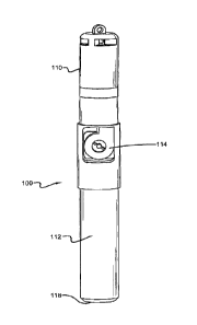
FIG. 1 is a rear perspective view of a first configuration of the vaporizing
device.
FIG. 2 is a front perspective view of the first embodiment of the vaporizing
device depicted in FIG. 1.
FIG. 3 is a front perspective view of a second embodiment of the vaporizing
device depicted in FIG. 1 used with a stand.
FIG. 4 is an exploded perspective view of the first configuration of the
vaporizing device.
FIG. 5 is a section view of the first configuration of the device.
FIG. 6 is a section view of the burner holder.
FIG. 7 is a front perspective view of an alternative end cap.
FIG. 8 is an exploded view of the alternative end cap showing the pieces
disassembled for refilling.
FIG. 9 is a view taken along line 9-9 of FIG. 8 showing the refill opening.
FIG. 10 is a front elevation view of a second configuration of the vaporizing
device.
FIG. 11 is a rear elevation view of the second configuration of the vaporizing
device depicted in FIG. 10.
FIG. 12 is an exploded view of the second configuration.
FIG. 13 is a section view of the second configuration.
FIG. 14 is a perspective view of a sealing cap.
FIG. 15 is a section view showing the sealing cap fully inserted.
6
CA 02928110 2016-04-25
FIG. 16 is an exploded view showing a key used to install and remove the
burner.
FIG. 17 is a section view showing the burner installed with the key.
FIG. 18 is an exploded view of an alternative fan configuration.
FIG. 19 is a view of an exemplary configuration with a hand-powered
squeeze-type airflow generator.
FIG. 20 is a view of another exemplary configuration with a hand-powered
squeeze-type airflow generator.
FIG. 21 is a view of another exemplary configuration with a hand-powered
squeeze-type airflow generator.
FIG. 22 is a view of another exemplary configuration with a hand-powered
squeeze-type airflow generator.
FIG. 23 is an exploded view of another exemplary configuration wherein a
hand-powered squeeze-type airflow generator provides the airflow to the
device.
FIG. 24 depicts one exemplary hand-powered squeeze-type airflow generator
with a valve to control airflow.
FIG. 25 depicts another exemplary hand-powered squeeze-type airflow
generator with a manual valve to control airflow.
FIG. 26 depicts the electric vaporizer that is used to create the vaporized
scent.
FIG. 27 depicts a cap that can be used on the hand-powered squeeze-type
airflow generator or on the end of the electric vaporizer.
FIG. 28 depicts the cap on the hand-powered squeeze-type airflow generator.
Similar numbers refer to similar parts through the specification.
DETAILED DESCRIPTION OF THE DISCLOSURE
7
CA 02928110 2016-04-25
The different configurations of the vaporizing device of the disclosure are
indicated generally by the numeral 100 in the accompanying drawings. When
assembled for use, each of these configurations generally includes a power
source,
a heating device, and a reservoir that contains a liquid scent material that
vaporizes
into an airborne scent that can be used as a lure designed to attract hunting
game,
as a repellant, as an air freshener, or as a scent eliminator. Device 100 can
be
provided to the user without a power source with the power source being
supplied by
the end user. Some of the configurations include an airflow generator such as
an
electric fan, a canister of compressed gas, or a squeezable bladder that is
used to
create a flow of air or gas that distributes the vaporized scent material from
device
100. One configuration is operated by an on-off switch. Another configuration
includes a timer that controls the operation of the device. A further
configuration
includes a sensor that activates the device when an airflow through the device
is
detected. An option is to provide a timer that is programmable by the user.
The
timer controls the creation and distribution of the vaporized scent material.
These
power options can be used alone or in combination. One configuration provides
a
refillable liquid cartridge while another configuration provides a sealed
liquid
cartridge that is removed and replaced after depletion. The cartridge carries
the
liquid scent material that is vaporized. One configuration of the cartridge
simply
includes the liquid composition that is vaporized. Another configuration of
the
cartridge includes the liquid composition as well as the burner element. The
cartridges are selectively connectable to the other components or another
component of device 100 to allow the user to readily recharge the device for
continued use. These general elements of device 100 may be used alone or in
combination with each other and the other elements described below to define
the
different configurations of device 100.
Although the following descriptions refer to the exemplary configuration of
FIGS. 1-5, the descriptions are also relevant to the other configurations
disclosed
herein and, as noted above, similar numbers refer to similar parts of the
configurations. Device 100 includes a removable and replaceable cartridge 110
and
a base 112. Cartridge 110 carries the liquid scent material that is vaporized
to form
the airborne vaporized scent material which can be used as an aromatic hunting
lure, a cover scent, a repellent scent, a room or automobile air freshener, or
a scent
8
CA 02928110 2016-04-25
eliminator. In this exemplary configuration, cartridge 110 also carries a
burner that
functions as the heating device that vaporizes the liquid scent material. The
heating
device can be rapidly heated to a temperature sufficient to rapidly vaporize
(less than
one to three seconds) the liquid scent material that is in close proximity or
in contact
with the heating device. The heating device can be heated to a temperature of
390-
480 degrees Fahrenheit. In one exemplary embodiment, the liquid scent material
is
heated to a temperature sufficient to change the liquid scent material from
the liquid
state to the aerosolized vapor. Other temperature ranges can be used to
vaporize
the liquid scent material.
Base 112 carries an airflow generator in the form of an electrically-powered
fan 114 that creates a flow of air that is delivered to cartridge 110 to
distribute the
vaporized scent material from device 100. Base 112 also carries a power source
116. Optionally, base 112 includes an on-off switch 118. Additional options
carried
by base 112 include a controller 120 that can be in the form of a programmable
timer
that provides the user a selection of preset operating modes or a programmable
controller that allows the user to customize the operation of device 100 to
match the
hunting conditions.
Base 112 carries a power source 116 such as a battery or a plurality of
batteries which can be disposable or rechargeable. Power source 116 can be
removable. Power source 116 is carried by a power source housing 130 that
forms
part of base 112 and can carry the optional on-off switch 118. Switch 118 can
be
located at the lower end of device 100 and is in the form of a push button
style on-off
switch or a twisting or rotating-style switch.
In one configuration, to turn on the unit, the user presses and holds the
button
118 on the control center 120 for five seconds. The user then immediately
chooses
the disbursement interval, by pressing the button 118 on the Control Center
120
briefly. A light will come on immediately followed by the unit indicating a
five second
scent disbursement. This light can be any one of the lights or a combination
of all
lights. Three options of adjustment are indicated by the color of light on the
control
center 120. Red: one minute intervals between scent disbursements. Yellow:
three
minute intervals between scent disbursement. Green: five minute intervals
between
scent disbursement. To turn the unit off, the user presses and holds the
button 118
9
CA 02928110 2016-04-25
on the control center 120 for five seconds. All lights will turn off and scent
disbursements will stop.
The connection between power source housing 130 and fan housing 132 of
base 112 functions as the negative ground for the power circuit of device 100.
The
connection between housings 130 and 132 can be a threaded connection 134 or a
snap-together connection. A seal in the form of an 0-ring can be provided to
make
the connected water-resistant or water-proof.
In order to form this part of the electric circuit of device 100, electrically
conductive elements are provided in base 112 that are in electrical contact
with the
negative side of power source 116. In the exemplary configuration, housings
130
and 132 are fabricated from an electrically conductive metal and the housings
themselves define part of the electrical circuit. In other configurations,
housings 130
and 132 can be fabricated from a material that is electrically insulating and
conductive elements are be carried by each housing 130 and 132 to define the
negative side of the electrical circuit.
The positive side of power source 116 is contacted by an electrical connector
136 that either extends into power source housing 130 or is recessed within
fan
housing 132. These positive and negative sides of the electrical circuit
provide the
electrical power for fan 114, controller 120 and the vaporizing coil of device
100.
The use of a removable power source 116 carried by housing 130 allows
charged replacement power sources 116 to be quickly added to fan housing 132
as
needed. The removable power source housing 130 allows optional attachments
such as flashlight attachments, power adapters for charging phones, radio
attachments, and other powered devices to be used with power source housing
130.
In one optional configuration, switch 118 is disposed on the side of housing
130 and
a flashlight attachment can be selective added to the end of device 100.
In one configuration, power source 116 is integrated into housing 130 such
and is not readily removable from housing 130. Such a power source 130 can be
a
rechargeable-type of power source 116. The user can swap housings 130 in the
field in a situation where the power is low. The housing can include a
charging port.
CA 02928110 2016-04-25
Device 100 can be provided in a simple on-off configuration wherein device
100 forms and dispenses vapor when the users turns device 100 on and stops
when
the user turns device 100 off. Device 100 can be provided with controller 120
that
provides operating configurations that are more useful for some hunting
situations.
In the configuration depicted in FIG. 2, controller 120 includes a single
button (switch
118 is used in the configuration of FIG. 10) and a plurality of indicator
lights that
indicate the operating condition of device 100. Each operating condition is
preprogrammed for a different distribution timing pattern. For example, the
first
condition can be a long continuous distribution of vapor (such as ninety
seconds)
followed by ninety minutes of short bursts (such as ten seconds) spaced apart
every
three minutes. The second configuration can be set to distribute medium bursts
(thirty seconds) at longer time intervals (every ten minutes) for an extended
time
(such as two hours). The third and fourth conditions can have other variations
such
as short - long - short and very long - very long - very long. Programmable
controller
120 allows the user to define the distribution pattern of device 100.
Controller 120
allows the user to control the timing of the vapor distribution, the time
intervals
between distributions, and the volume of the vapor distribution. Controller
120 can
include a programmable circuit board 140 that includes a timer. The settings
of
controller 120 can be changed through push buttons accessible to the user
(three
button are depicted as examples - more or fewer can be used). A visible screen
142
can be used to display the settings to the user. In other configurations, a
wireless
communications circuit is used to allow the user to communicate with
controller 120
through WIFI or Bluetooth communications protocols such that device 100 can be
set up through software on a user's phone or other mobile computer. An
exemplary
setting for the operation of the device is to vaporize for three seconds and
then turn
off for ninety seconds when the sequence is repeated. This sequence can be set
to
repeat a number of times or for a length of time as desired by the user.
Fan housing 132 defines one or a plurality of air channels 148 for the air
flow
created by fan 114. Air channels 148 extends from the exit of fan 114 to the
upper
end of base 112. When cartridge 110 is connected, the outlet of air channel
148 is in
communication with a plenum 146 that receives a lower end portion of the
burner
150. The removable and replaceable cartridge 110 contains the liquid that is
vaporized by device 100 and the burner 150 that, when powered or energized, is
CA 02928110 2016-04-25
adapted to vaporize a selected volume of the liquid. Burner 150 defines an air
inlet
160 that is in fluid communication with plenum 146 when cartridge 110 is
installed.
The air flow from fan 114 pressurized plenum 146 causing air flow into inlet
160 and
through an air flow channel 162 defined by burner 150 from inlet 160 to its
outlet
164.
Before cartridge 110 is connected to fan housing 132, cartridge 110 is
substantially sealed such that the user is not readily exposed to the liquid
during the
transport and storage of cartridge 110. A removable seal can be provided over
the
lower end of cartridge 110. This seal is either removed by the user or pierced
by
base 112 during the installation of cartridge 110. Another configuration only
seals air
inlets 160 with a removable or meltable seal. The upper end of cartridge 110
can be
sealed with its own removable seal or the top portion of cartridge 110 can be
rotated
between a sealed condition and an open condition.
When cartridge 110 is installed, a gasket, seal, or 0-ring 152 forms a seal
between the burner holder 154 and the top of fan housing 132. The connection
between burner holder 154 and fan housing 132 can be a snap fit, a threaded
connection, or a slide and twist locking connection similar to a bayonet
connection.
In the configuration wherein the installation of cartridge 110 is designed to
pierce the
lower seal of cartridge 110, the remaining portions of that seal remain on
cartridge
110 and form seal 152 when the cartridge 100 is fully seated on fan housing
132.
Burner 150 defines a liquid scent material inlet 170. Within burner 150 in
fluid
communication with both channel 162 and inlet 170 is a heating element 172 and
a
wick 174. Heating element 172 is an electric resistive heating-style element
(burner
coil) that creates heat when electric current is passed through element 172.
Wick
174 limits the amount of liquid that is brought into contact or proximity with
heating
element 172. Wick 174 can be a screen having small openings or an absorbent
material. Electricity is delivered to heating element 172 through burner 150
and the
circuit is formed through burner holder 154.
Burner 150 is seated in burner holder 154 against an inner shoulder 155
defined by burner holder 154. This connection can be used to form the negative
electrical connection between burner holder 154 and heating element 172.
Burner
150 can be held in place by being sandwiched between shoulder 155 of holder
154
12
CA 02928110 2016-04-25
and end cap 182. A burner cap seal 178 forms a seal between burner 150 and end
cap 182. Alternatively or in combination with the sandwiched fit, burner 150
can be
held by a friction fit, a threaded connection, or a snap fit. Burner 150
defines a
shoulder 176 that seats against inner shoulder 155 of burner holder 150. A
seal is
disposed between burner 150 and the inner surface of burner holder 154. This
connection provides that air inlet 160 is in fluid communication with plenum
146 of
burner holder 154. The upper end 179 of burner holder 154 is funnel shaped to
direct the liquid into inlet 170.
Burner 150 extends to engage a central portion 180 of end cap 182. Central
portion 180 defines a vapor distribution channel 186 of end cap 182. End cap
182
defines a plurality of vapor outlets 188 that allow the vapor to be
distributed about
the entire perimeter of the device.
End cap 182 defines a liquid holding chamber 190 that holds the liquid
aromatic lure material. Inlet 170 of burner 150 is exposed to the liquid in
chamber
190. Chamber 190 is defined between the outer surface of central portion and
the
inner surface of the outer wall 192 of end cap 182. Chamber 190 is thus
substantially ring-shaped and surrounds vapor distribution channel 186. End
cap
182 is mounted to burner holder 154 with a mounting collar 200 by threads,
snap fit,
adhesive, or weld/fusion. A seal such as an 0-ring 202 can be used as needed.
End cap 182 can define a mounting hole 210 for a lanyard that keeps device
100 in a generally upright configuration so that any liquid in the liquid
holding
chamber 190 is disposed against the heating element 172 or the wick 174 for
the
heating element 172 by gravity.
Cartridge 110 is used and discarded. Heating element 172 eventually bums
out which allows burner 150 to be disposed with cartridge 110. Disposable
cartridges 110 allow the user of device 100 to stay out of contact with the
liquid lure
and does away with the problem of refilling device 100. When device 100 is
empty,
the user simply removes cartridge 100 by disconnecting burner holder 154 from
fan
housing 132. A new cartridge 110 is added and device 100 is ready to use.
In an alternative configuration, the replacement cartridge does not include
burner 150. In this configuration, end cap 182 is removed after it is used and
a full
end cap 182 is replaced onto burner holder 154.
13
CA 02928110 2016-04-25
In another alternative configuration, end cap 182 has a refill opening 220
that
allows the user to refill liquid into chamber 190 as needed. This
configuration is
depicted in FIGS. 7-13 and 14-15 wherein end cap 182 is provided in first 216
and
second 218 portions. First portion 216 defines liquid holding chamber 190 and
defines refill opening 220. Second portion 218 screws onto first portion 216
and
seals opening 220 when tightened. A flexible seal 222 (FIG. 12) can be used to
seal
opening 220. This configuration allows chamber 190 to be refilled with the
liquid
scent material.
FIGS. 14-15 depict a sealing cap 224 that is connected to first portion 216 of
end cap 182 when second portion 218 is removed. Sealing cap 224 has a first
disc-
shaped portion 225 that sits on top of first portion 216 to seal liquid
holding chamber
190. Sealing cap 224 includes threads defined along the inner surface of an
outer
flange that cooperate with the threads on first portion 216 to secure sealing
cap 224
with a threaded connection. Sealing cap has a second elongated portion 226
that
extends into first portion 216 to slide into burner 150 (shown in FIG. 15) to
close off
inlet 170. Second elongated portion 226 can extend to close off inlet 160.
Optionally, a second cap can be used over the lower end of burner 150 if
desired.
When threads are not used, second elongated portion 226 can frictionally
engage
central portion 180 to connect sealing cap 224 to first portion 216. The lower
end of
second elongated portion 226 sealingly engages burner 150 to form the seal.
Sealing cap 224 can be made from a resilient material such as rubber to allow
it to
compress when engaged with first portion 216 to form a liquid-tight seal.
In the configuration of FIGS. 10-16, burner 150 is connected to burner holder
154 with a threaded connection between a threaded burner nut 230 and burner
holder 154. FIGS. 16 and 17 depict the cartridge with the manner in which the
burner 150 is mounted to the cartridge with a threaded burner mount 154 and
nut
230 and the key 232 that can be used to install and remove burner 150. Key 232
can double as a promotional item. As described above, the upper end of burner
150
engages and seals with central portion 180. Threaded burner nut defines at
least two
spaced key holes that receive corresponding key prongs on key 232 to allow the
user to rotate threaded burner nut 230 with key 232. A seal 234 is provided
between
nut 230 and burner holder 154 which, in cooperation with the threads, seas the
lower
14
CA 02928110 2016-04-25
end of chamber 190. This seal can also be compressed to function as a locking
device for the threaded connection.
FIGS. 10-18 depict an alternative version of power source housing 130 and
fan housing 132 with an exemplary configuration for a single switch 118 used
to
control device 100. Different operational modes are selected by the number of
times
switch 118 is depressed or by the length of time switch 118 is held down.
FIGS. 10-18 depict an optional protective housing 240 disposed around a
portion of fan housing 132 and covering the fan intake opening of fan housing
132.
In this configuration, protective housing 240 is transparent to allow the user
to view
indicator lights on controller 120. Switch 118 extends through housing 240 to
allow
the user to manually change the settings. Switch 118 defines a seal with the
opening in housing 240. In configurations wherein controller 120 communicate
wirelessly with a mobile computer, switch 118 and the opening in housing 240
can
be eliminated. Housing 240 can form a sealed connection with a flange 241
projecting from housing 132. Housing 240 has a raised section 242 that defines
an
inlet plenum 244 over the fan inlet. The raised section defines the air inlet
for the
fan. A perforated grid can be disposed over the fan inlet. A fan inlet opening
246
can be defined by housing 240 or though flange 241 or both_ Housing 240
protects
controller 120 and fan 114 from liquids and other debris.
Controller 120 can control the delivery of power to burner 150 or an airflow
sensor 248 can be used to active burner 150 whenever fan 114 is generating an
airflow. When sensor 248 is used, controller 120 controls the operation of fan
114
and the delivery of power to burner 150 is controlled by sensor 248. Sensor
248 can
operate by being moved by the airflow to provide an electrical connection.
FIG. 18 depicts an alternative configuration for the fan housing 132 wherein
fan 114 is mounted with its axis of rotation parallel to the longitudinal axis
of device
100. A magnetic mount 250 is used to hold fan 114 in place. Magnetic mount 250
is
provided as a magnetic ring over which fan 114 is seated. The air is pulled
into fan
housing 132 through a plurality of openings disposed across from controller
120. In
this configuration, the lower end of housing 132 carries sealed a water proof
pad to
prevent water from entering the air openings and moving into the battery
housing.
CA 02928110 2016-04-25
FIGS. 19-28 disclose configurations wherein a manually-operable airflow
generation device 260 is used to create vapor distribution airflow through
device 100
to distribute the vapor created by burner 150. Manually-operable airflow
generation
device has first and second configurations. Device 260 can be a squeezable
flexible
bladder that, when squeezed from the first to the second configuration,
reduces its
interior volume to expel a portion of the air within the bladder out of an
outlet. The
manual airflow generation device also can be a manually-operated fan such as a
plurality of fan blades that spin when a crank is turned or when a trigger is
pulled.
Another configuration includes a bellows-style airflow generator that creates
an
airflow when elements pivot toward each other.
In each of the configurations of FIGS. 19-28, burner 150 of device 100 can be
activated with a manually-operated power button or a sensor that senses
airflow,
pressure changes, temperature change of the airflow or senses a change in the
dimensions of the bladder wall of manually-operable airflow generation device
260.
The sensor can be a biased member such as a plunger or membrane that moves in
reaction to the airflow and forms an electrical connection between the power
source
and the burner to rapidly vaporize the liquid scent material in response to
the airflow.
In one embodiment, the airflow created by the bladder moves a biased member
that
brings an electrical contact into electrical contact with another electrical
contact to
complete a circuit and power burner 150. In these configurations, burner 150
can be
provided in the configurations described above or as an electrical resistive
heating
element such as a coil of thin wires or strands of metal.
In each of the configurations of FIGS. 19-28, a resilient bladder,260 is used
to
generate the airflow through device 100. Each bladder 260 is made from a
resilient
material that can be deformed when a compressive force is applied to the
outside of
the bladder wall. The bladder wall can be designed to automatically return to
its
uncompressed state when the compressive force is released. Alternatively, a
resilient foam material 262 can be disposed inside bladder 260 to help bladder
260
to maintain its shape and to help bladder 260 return to its resting condition
after
being squeezed. In other configurations, a mechanical spring is used to help
push
the bladder wall back to its resting condition. These items can be used alone
or in
combination with one another or in combination with the wall material of the
bladder
itself. Also, each bladder wall can be configured to return to the resting
position
16
CA 02928110 2016-04-25
through the resiliency of the material used to form the bladder wall combined
with the
shape or configuration of the bladder wall itself.
Also in the configurations of FIGS 19-28, each bladder 260 can be provided
with a one-way valve 274 and/or a manually-operated valve 276. A one-way valve
274 allows air to flow into bladder 260 but prevents air from exiting bladder
through
valve 274. Although valve 274 can be disposed anywhere on bladder 260, valve
274
can be carried by bladder 260 at a portion of bladder 260 that is not
substantially
deformed when bladder 260 is squeezed. Such a portion can be the bottom wall
of
bladder 260. As an addition or as an alternative to valve 274, an opening 276
can
be defined by the wall of bladder 260. Opening 276 functions as a manual valve
that
must be covered by the user's finger when squeezing to force air toward burner
150_
A benefit of opening 276 is that it prevents unintentional actuation of device
100 by
allowing air flow out of bladder 260 when the user unintentionally squeezes
bladder
260. This allows device 100 to be carried in the user's pocket without worry
about
undesired activation.
In any of these configurations, an additional one-way valve positioned
downstream of the outlet of bladder 260 can be used as an option to prevent
back
flow from burner 150. An example of this configuration is depicted in FIG. 20.
Each of the configurations of FIGS. 19-28 uses a version of an electric
vaporizer 280. Electric vaporizer 280 can include a power source 270 or can be
removably connected to power source 270. Electric vaporizer 280 includes
burner
150 in the configuration described above or as a stripped down configuration
with
just the wick material and burner coil. Electric vaporizer 280 also includes
an air inlet
282, a supply of liquid scent material 284, and a vapor outlet 286. Electric
vaporizer
280 can be disposable or refillable. Electric vaporizer 280 can be energized
by a
manual switch 288 or a sensor 290 as described above.
In the configuration of FIG. 19, a power supply 270 is disposed in a power
supply housing 272 which is substantially surrounded with a squeezable air
bladder
260 that, when squeezed, delivers an airflow to burner 150. Power supply
housing
172 selectively receives electric vaporizer 280 which is connected through the
threaded connection depicted in FIG. 19, a snap fit connection, or a friction
connection. In the FIG. 19 configuration, a power lead is provided to supply
power to
17
CA 02928110 2016-04-25
vaporizer 280. In the FIG. 19 configuration, bladder 260 substantially
surrounds
power supply housing 272 with at least a majority of electric vaporizer 280
being
disposed outside bladder 260 in an extended configuration where it can be
readily
replaced.
In the configuration of FIG. 20, the bladder 260 surrounds the entire length
of
electric vaporizer 280 and power supply 270. The main air intake valve 274 is
disposed at the bottom of device 100. A sensor 290 such as an air pressure
sensor
is used to active the burner coil when the user squeezes the bladder 260 to
generate
airflow into the coil. The FIG. 20 configuration includes a second valve 274
to
prevent backflow.
In the configuration of FIG. 21, the airflow generator bladder 260 is disposed
at the location of the fan inlet of FIG. 1. In this configuration, the bladder
260 is
shaped to fit the user's hand so that the user grips the bladder 260 and the
housings
with a single hand. When a power button 288 is used, the user's thumb or
finger can
control the power button 288 while the palm of the hand compresses the bladder
260
to generate the airflow to the burner coil 150. A sensor (such as sensor 290)
can be
used as an alternative to or in addition to switch 288. A valve can be used to
control
the airflow into bladder 260. A secondary valve can be used to prevent suction
back
into the bladder from the coil.
In the configuration of FIG. 22, the airflow generator bladder 260 is disposed
opposite the power source 270 and pushes air down through the liquid holding
tank
184 and then through the vaporizing coil 150. An inlet valve 274 can be used
to refill
the bladder 160. In this configuration, power button 288 turns unit 100 to an
'on'
configuration while sensor 290 is used to energize burner 150.
FIG. 23 is an exploded view of another exemplary configuration wherein a
hand-powered squeeze-type airflow generator is provided in the form of a
resilient
bladder 260 that provides the airflow to the device 100. In this
configuration, bladder
260 is provided with a one-way valve 274 and/or a manual valve 276 that
control the
airflow delivery to an electric vaporizer 280. Valve 274 allows bladder 260 to
refill
with air after being squeezed. Valve 276 must be covered with the user's
finger or
thumb to prevent air from being squeezed out of valve 276. The user then
uncovers
valve 276 to allow bladder 260 to refill with air. FIG. 24 depicts one
exemplary hand-
18
CA 02928110 2016-04-25
powered squeeze-type airflow generator 260 with valve 274 to control airflow.
FIG.
25 depicts another exemplary hand-powered squeeze-type airflow generator 260
with manual valve 276 to control airflow.
FIG. 26 depicts an electric vaporizer 280 that is used to create the vaporized
scent material. Electric vaporizer 280 includes a power source 270 such as a
battery
or rechargeable battery, an airflow passage extending from an inlet 282 to an
outlet
286 to allow the airflow generated from bladder 260 to be delivered to a
burner 150.
Electric vaporizer 280 can include a power button (optional) that energizes
burner
150 and/or electric vaporizer 280 includes a sensor 290 (optional) that
automatically
energizes burner 150 when sensor 290 is subjected to airflow from bladder 260.
Sensor 290 can be a biased plunger that moves in response to the airflow to
form
the electrical connection between power source 270 and burner 150. Sensor 290
also can be an air pressure sensor configured to energize burner 150 in
response to
an increase in the air pressure in vaporizer 280. The liquid scent material is
carried
by a liquid holding tank 284 in fluid communication with burner 150. Electric
vaporizer 280 defines an outlet 286 to allow the airflow to distribute the
vaporized
material.
FIG. 27 depicts a cap 292 that can be used to close outlet 286 and/or to
provide a lanyard opening to allow the device having cap 292 to be hung from
one's
belt or coat. FIG. 28 depicts the cap 292 on the hand-powered squeeze-type
airflow
generator. In this configuration, a majority of electric vaporizer 280 is
disposed
within a rounded, oval bladder with cap 292 adapted to selectively cover the
outlet
end of electric vaporizer 280 that extends from bladder 260. Cap 292 can be
snap
fit, friction fit, or threaded onto vaporizer 280 to secure it in place and to
allow the
device to be hung from a clip or lanyard. In another configuration similar to
the one
depicted in FIG. 20, electric vaporizer 280 is disposed entirely inside
bladder 260. In
this configuration, cap 292 can engage the upper end of bladder to cover
outlet 286.
In both of these configurations, electric vaporizer 280 is removable and
replaceable
so that a different electric vaporizer 280 can be installed. Bladder 260 can
resiliently
engage the outer surface of vaporizer 280 to define a seal. A clamping ring
can be
provided to tighten the seal.
19
CA 02928110 2016-04-25
In each of the embodiments describe above, the liquid scent material that is
being vaporized can be a combination of a glycol substance with an aromatic
material or a scent-elimination material. The aromatic material can be a solid
or
liquid animal lure substance. The glycol substance can be a propylene glycol,
a
vegetable glycerin, a combination of both, and/or a combination of these with
water.
The animal lure aromatic material can be a liquid or solid animal urine or
glandular
secretion. The solid materials can be made by dehydration. In any of these
combinations, water can be added as needed. The dehydrated urine can be formed
by freeze drying, flash drying liquid urine, or otherwise dehydrating the
liquid urine to
form the additive to the glycol. The aromatic material can be designed to
repel
animals or insects and can thus be a predator smell or a citronella. The
aromatic
material can be a cover scent used by a hunter to cover his scent when
entering or
leaving a hunt area. The aromatic material can be a pleasant-smelling material
that
one can use to freshen room air or an automobile. These aromatic materials can
be
clean-smelling materials, flower-based materials, fruit-based materials,
pleasant-
smelling food materials, pleasant-smelling outdoor smells, spices, tropical
smells,
and others enjoyable to human users. These can be provided as oils or powders
and mixed with the glycol.
Device 100 has the advantage of only vaporizing the liquid scent material on
demand. The device does not waste the liquid scent material by continuously
vaporizing unless the user selects continuous operation as an option. The
device
will function in cold weather and the vaporized glycol-based vapor substance
hangs
in the air and does not distribute itself in the air as fast as other scent
materials. The
electric heating element does not create any additional fuel scent through a
combustion process. The removable and replaceable cartridges keep the scent
fresh and allow the user to readily refill the device without skin contact
with the scent
liquid. There is also no risk of spilling the liquid. The user can program the
device to
automatically freshen the scent at intervals.
One method of using device 100 is to provide device with a repellant scent
that drives game away from the scent. Device 100 is then used along a boundary
or
in an area such as a user's yard wherein the user does not want the game to
cross
or to congregate. The repellant material can include the scent of a predator,
a soap,
a human, a dog, or the like. The user can set a scent fence line of vaporizing
CA 02928110 2016-04-25
devices timed to form and distribute the vaporized scent at periodic times.
This
creates a scent barrier than helps keep game from passing through the area.
This
configuration of the device can be used to deter game such as deer from
entering a
garden area or a landscaped area where the deer feed on the plantings.
Another use for device 100 is to provide a vaporizable material in device 100
that reduces or eliminates scent particles from the air that is exposed to the
vaporized material. This device is used for scent elimination. The disclosure
provides a vaporizable mixture that includes a percentage of carbon, charcoal,
activated carbon, or coconut shell activated carbon, or palm kernel shell
charcoal or
a combination of these substances. The combination of these substances with a
vaporizable material such as the glycol materials discussed above allow a
scent
elimination substance to be generated to be used by a hunter to eliminate or
reduce =
scents that can alert game to the hunter's presence.
An optional alternative use for the device is to attach a scent cartridge to
the
device that creates a pleasant smelling vapor for use in deodorizing a
vehicle, a
house, clothing, and the like. An advantage here is that by using the
removable
cartridge, there is no deer urine scent left on the device when a pleasant
smelling
scent is installed. This is especially true when the cartridges carry their
own burner
coils. As such, the same device used to distribute the deer urine smell can
also be
used to distribute a pleasant smelling vapor - such as a vanilla - for the
hunter's
vehicle on the drive home.
In the foregoing description, certain terms have been used for brevity,
clearness, and understanding. No unnecessary limitations are to be implied
therefrom beyond the requirement of the prior art because such terms are used
for
descriptive purposes and are intended to be broadly construed. Moreover, the
descriptions and illustrations of the exemplary configurations are examples
and the
claimed invention is not limited to the exact details shown or described.
Throughout
the description and claims of this specification the words "comprise" and
"include" as
well as variations of those words, such as "comprises," "includes,"
"comprising," and
"including" are not intended to exclude additives, components, integers, or
steps.
21