Note: Descriptions are shown in the official language in which they were submitted.
CA 02934685 2016-06-29
ACTIVE MONITORING OF ALIGNMENT OF RIG COMPONENT
FIELD OF DISCLOSURE
[I] The present disclosure relates generally to wellbore drilling
operations, and more
particularly to measuring an alignment condition of a rig component.
BACKGROUND
[2] Drilling subterranean wells for oil and gas is expensive and time
consuming.
Formations containing oil and gas are typically located thousands of feet
below the earth's
surface. To access the oil and gas, thousands of feet of rock and other
geological formations
must be removed. To ensure a cost-effective drilling operation, equipment
utilized in
wellbore drilling operations must be capable of repeated, reliable operation.
Damage to
components of a drilling rig due to misalignment in the wellbore can cause
equipment to fail
and can shut down an operation, rendering the drilling operation economically
unsustainable.
The industry continues to demand improvements in subterranean drilling
operations.
BRIEF DESCRIPTION OF THE DRAWINGS
[3] Embodiments are illustrated by way of example and are not limited in
the
accompanying figures.
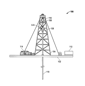
[4] FIG. 1 includes a schematic view of a drilling rig.
[5] FIG. 2 includes a partially cut away front perspective view of a
junction box disposed
on a top drive in accordance with an embodiment.
[6] FIG. 3 includes a side perspective view of FIG. 2.
[7] FIG. 4 includes a simplified schematic of an active sensing and
continuous (real time)
information relaying operation adapted to sense and actively relay an
alignment condition in
accordance with an embodiment.
[8] Skilled artisans appreciate that elements in the figures are
illustrated for simplicity
and clarity and have not necessarily been drawn to scale. For example, the
dimensions of
some of the elements in the figures may be exaggerated relative to other
elements to help to
improve understanding of embodiments of the invention.
1
CA 02934685 2016-06-29
DETAILED DESCRIPTION
[9] The following description in combination with the figures is provided
to assist in
understanding the teachings disclosed herein. The following discussion will
focus on specific
implementations and embodiments of the teachings. This focus is provided to
assist in
describing the teachings and should not be interpreted as a limitation on the
scope or
applicability of the teachings. However, other embodiments can be used based
on the
teachings as disclosed in this application.
[10] The terms "comprises," "comprising," "includes," "including," "has,"
"having" or any
other variation thereof, are intended to cover a non-exclusive inclusion. For
example, a
method, article, or apparatus that comprises a list of features is not
necessarily limited only to
those features but may include other features not expressly listed or inherent
to such method,
article, or apparatus. Further, unless expressly stated to the contrary, "or"
refers to an
inclusive-or and not to an exclusive-or. For example, a condition A or B is
satisfied by any
one of the following: A is true (or present) and B is false (or not present),
A is false (or not
present) and B is true (or present), and both A and B are true (or present).
[11] Also, the use of "a" or "an" is employed to describe elements and
components
described herein. This is done merely for convenience and to give a general
sense of the
scope of the invention. This description should be read to include one, at
least one, or the
singular as also including the plural, or vice versa, unless it is clear that
it is meant otherwise.
For example, when a single item is described herein, more than one item may be
used in
place of a single item. Similarly, where more than one item is described
herein, a single item
may be substituted for that more than one item.
[12] Unless otherwise defined, all technical and scientific terms used herein
have the same
meaning as commonly understood by one of ordinary skill in the art to which
this invention
belongs. The materials, methods, and examples are illustrative only and not
intended to be
limiting. To the extent not described herein, many details regarding specific
materials and
processing acts are conventional and may be found in textbooks and other
sources within the
drilling arts.
[13] The concepts are better understood in view of the embodiments described
below that
illustrate and do not limit the scope of the present invention. The following
description
includes a tool for wellbore operations. Certain embodiments of the tool can
include a sensor
adapted to measure an alignment condition of a rig component. The alignment
condition can
include the relationship between the actual position of the rig component and
its alignment
position. As used herein, the term "alignment position" refers to a reference
position used to
2
CA 02934685 2016-06-29
determine the alignment of the rig component and will be discussed in more
detail below. In
certain embodiments, the tool can measure the alignment condition continuously
(in real-
time) and relay the condition to a user. Further, the description includes a
system for use in
subterranean operations. The system can include a sensor and a computing
system in
communication with the alignment sensor to determine, for example, adjustments
to the rig
component based on its alignment condition. Furthermore, the description
includes a method
of operating a system for subterranean operations. The method can include
acquiring an
alignment condition and adjusting a rig component to change the alignment
condition of the
rig component.
[14] The term "alignment condition" refers to the alignment status of the rig
component
based on the proximity of the rig component to its alignment position. In
certain
embodiments, the alignment condition can include at least an aligned
condition, where the
proximity of the rig component to its alignment position is within an
acceptable range, and a
misaligned condition, where the proximity of the rig component to its
alignment position is
outside of an acceptable range.
[15] In certain embodiments, the proximity of the rig component to its
alignment position
can include the angle of departure of the actual position of the rig component
from the
alignment position. For example, sensing and generating data regarding an
alignment
condition can include measuring an angle of departure of the actual position
of the rig
component (or an axis of the rig component) from an alignment position. In
particular
embodiments, the angle of departure can include a pitch angle, a roll angle,
or both. In
further embodiments, the tool can be sensitive enough to comply with the
engineered
tolerances of the machine being used. For example, the angle of departure can
be measured
at an interval sensitivity of at least 0.10, at least 0.010, or at least
0.0010.
[16] The smaller the angle of departure, the closer the rig component is to
its alignment
position. For example, the actual position of the rig component can approach
an aligned
alignment condition as the angle of departure approaches 0 . In certain
embodiments, the
alignment condition includes an aligned alignment condition when the angle of
departure is
no greater than 5 , no greater than 1 , no greater than 0.5 , or even no
greater than 0.1 .
[17] Conversely, the larger the angle of departure, the farther the rig
component is from its
alignment position. For example, the actual position of the rig component can
approach a
misaligned alignment condition when the angle of departure moves away from 0 .
In certain
embodiments, the alignment condition includes a misaligned alignment condition
when the
angle of departure is at least 0.1 , at least 0.5 , at least 1 , or even at
least 5 .
3
CA 02934685 2016-06-29
[18] As stated previously, an alignment position is a reference position used
in determining
the alignment condition of the rig component. In certain embodiments, the
alignment
position can include at least one axis, at least two axes, or even at least
three axes. For
example, the alignment position can include a uniaxial alignment position
including a first
axis. As another example, the alignment position can include a biaxial
alignment position
including a first axis and a second axis. In any type of alignment position,
one or more of the
at least one axis can include a predetermined axis.
[19] In certain embodiments, the alignment position can include a first axis
and a second
axis where the first axis and the second axis are different compared to each
other. In
particular embodiments, the first axis can be orthogonal to the second axis.
For example, in
any type of alignment, the first axis can include true vertical or true
horizontal. Thus, in a
biaxial alignment position, the first axis can include true vertical and the
second axis can
include true horizontal, and vice versa. Further, instead of true vertical or
true horizontal, in
any type of alignment the first axis or second axis can be greater than 00
from true vertical or
from true horizontal, such as greater than 00 and less than 90 from true
vertical or from true
horizontal. Furthermore, in any type of alignment position, the first axis or
second axis can
include an axis of a second rig component. The second rig component can
include, for
example, a top drive, guide tracks a top drive, running gear disposed on a top
drive, or any
combination thereof Also, the second rig component can include a quill, a
drill string or at
least a portion of a drill string, such as a top portion of a drill string.
[20] In accordance with an embodiment of the present invention, FIG. 1 is a
simplified
schematic of a subterranean drilling operation 100. The drilling rig 100 can
be an offshore
drilling rig or a land based drilling rig. Offshore drilling rigs can take
many forms. For
example, the drilling rig 100 can have a fixed platform or substructure
attached to an
underlying seabed. Alternatively, the drilling rig 100 can include a floating
platform
disposed at least partially underwater with an anchoring system holding the
drilling rig 100
relatively near the underwater drilling operation. It should be understood
that the particular
configuration and embodiment of the drilling rig 100 are not intended to limit
the scope of the
present disclosure.
[21] As illustrated in FIG. 1, the drilling rig 100 can generally include a
substructure 102
and a derrick 104. The derrick 104 can be attached to the substructure 102 and
can extend
therefrom. The derrick 104 can be a tower or a guyed mast such as a pole which
can be
hinged at a bottom end. The derrick 104 and substructure 102 can be permanent
or can be
adapted to break down for transportation. In certain embodiments, the drilling
rig 100 can
4
CA 02934685 2016-06-29
further include a hoisting system 106, a top drive 108, and a power supply
110. While a top
drive 108 is shown, the principles of this disclosure can apply to any drive
system including a
top drive, a power swivel or a rotary table. The derrick 104 can support the
hoisting system
106 and the top drive 108. In a particular embodiment, the hoisting system 106
can include a
drawworks 114 and a block and tackle system 116 adapted to support a drill
string 118.
[22] Typically, a top drive is suspended from the derrick and is connected to
a drill string
via a main drive shaft (a short section of pipe known as a quill). The top
drive rotates the
quill which, in turn, rotates the drill string and the drill bit to produce a
well bore. A
misalignment of the top drive and the drill string can result in damage to the
quill, which can
cause equipment to fail and can shut down an operation. Manual alignment of
the top drive
and the drill string relative to an alignment position, such as true vertical,
has proven to be
either inaccurate or unable to account for misalignments that occur during
operation. For
example, the top drive can be suspended in the derrick by a traveling block
that allows the top
drive to move up and down the derrick where misalignment can occur. Further,
mobile drill
rigs have been developed that are capable of "walking" about a location and
such movements
are capable of resulting in a misalignment. Even when stationary, rig
foundations can shift or
settle. Such movement can result in a misalignment that occurs during
operation that can
damage rig components, such as the top drive or the drill string. Proper
orientation should be
monitored during operation to assist in realigning the mast sections or the
top drive and
avoiding damage to the rig components.
[23] In a particular aspect, at least one alignment sensor 200 (see FIG. 4)
can be coupled to
an equipment of the drilling rig 100 to actively sense and generate data
regarding an
alignment condition of a rig component relative to an alignment position. As
used herein,
"actively sense" refers to an act of sensing where a sensing condition occurs
at least once
every hour, such as at least once every 30 minutes, at least once every
minute, or even at least
once every 10 seconds. In a particular embodiment, "actively sense" refers to
an act of
sensing wherein a sensing condition occurs at least 1 time per minute (TPM),
such as at least
30 TPM, at least 60 TPM, at least 120 TPM, or even at least 300 TPM. Moreover,
in
particular embodiments, the alignment sensors can sense the condition no
greater than 5,000
TPM, such as no greater than 4,000 TPM, no greater than 3,000 TPM, no greater
than 1,000
TPM, no greater than 500 TPM, or even no greater than 300 TPM.
[24] The alignment sensor should be disposed in a location that allows the
alignment
sensor to measure the alignment condition. For example, the at least one
alignment sensor
200 can be coupled to the top drive 108, or integrated into a remote panel on
the top drive
CA 02934685 2016-06-29
108, such as in the junction box 120 illustrated in FIGs. 2 and 3. FIG. 2
includes a front view
of the junction box 120 relative to an x-axis and FIG. 3 includes a side view
of the junction
box 120 relative to a y-axis along the same plane as the x-axis. Further, the
alignment sensor
can be disposed in a fixed position on the top drive. The alignment sensor can
be fixed in
various ways including adhering the alignment sensor to the top drive. From
the top drive,
the alignment sensor can track the alignment condition (as discussed
previously) to
determine, for example, the misalignment of the top drive relative to the
mast.
[25] In certain embodiments, the alignment sensor can include an alignment
sensor that
can measure the angle of inclination of a rig component. For example, the
alignment sensor
can include an inclinometer. In particular embodiments, the inclinometer can
include a
microelectromechanical system (MEMS) or a nanoelectomechanical system (NEMS).
In
more particular embodiments, the inclinometer can include a dual axis
inclinometer. The
dual axis inclinometer can be configured to measure pitch and roll
inclination. In further
embodiments, the inclinometer can include a bubble inclinometer.
[26] In addition, the alignment sensor can include a linear alignment
indicator. For
example, the linear alignment indicator can include a laser alignment system.
In certain
embodiments, a laser alignment head can be coupled to a rig component, such as
the top
drive. The laser alignment head can direct a laser to a desired target
indicating an alignment
condition based on whether the laser engages with the target. In embodiments,
the target can
include a visual target where a user determines alignment based on visual
perception of
whether the laser engages the target. In other embodiments, the target can
include a sensor
target that can determine whether the laser engages the target without the
visual perception of
a user. In particular embodiments, the linear alignment indicator can be used
in combination
with the sensor measuring the angle of inclination. For example, the linear
alignment
indicator can measure offset alignment and the inclination sensor can measure
angular
alignment.
[27] In certain embodiments, the data from the alignment sensor, including an
alignment
condition of a rig component, can be transmitted, such as transmitted to a
computing system.
The data can be transmitted to assist in realignment of the rig components. As
discussed in
more detail below, the computing system can display the alignment condition on
a human-
machine interface (HMI), and the HMI can display the alignment condition using
adjustable
models of the rig components or other indicators of the alignment condition.
[28] In certain embodiments, the alignment sensor 200 can be disposed outside
a housing,
or in communication with an intermediary member disposed outside of the
housing by
6
CA 02934685 2016-06-29
electrical wiring extending through the housing or a wireless signal. In this
regard, the
alignment sensor 200 can communicate the sensed alignment condition to an
intermediary
member located outside of the housing of the equipment. In another embodiment,
the
alignment sensors 200 can be directly engaged with a logic element 202,
independent of an
intermediary member. The logic element 202 may be disposed immediately
proximate to the
alignment sensors.
[29] In a non-limiting embodiment, it may be advantageous to position at least
a portion of
each alignment sensor 200 at a location whereby the alignment sensor 200 can
be reached
and affected from an exterior location of the equipment. In another non-
limiting
embodiment, the alignment sensor 200 can be coupled to a portion of the
equipment that can
be readily removed or opened in order to expose the alignment sensor, e.g., a
sealable hatch
or access point. In such a manner, the alignment sensor 200 can be
manipulated, adjusted, or
even replaced without requiring significant operation upon the equipment.
[30] Referring now to FIG. 4, during drilling operations, one or more
alignment sensors
200 can actively monitor an alignment condition of the first rig component.
For example, the
alignment sensor can be monitored as part of a rig control system. After being
collected by
the alignment sensors 200, a sensed data relating to the alignment condition
of the first rig
component can be transferred (illustrated by line 208) continuously (in real
time) to a logic
element 202. As used herein "transferred continuously" refers to a
transmission of data at
least once every hour, such as at least once every 30 minutes, at least once
every minute, or
even at least once every 10 seconds. In a particular embodiment, "transferred
continuously"
refers to a transmission of data at least once every 30 minutes. In yet a more
particular
embodiment, "transferred continuously" refers to the transmission of data as
it is obtained at
each sensed interval, i.e., data is immediately transferred from the alignment
sensors to the
logic element. In a particular embodiment, a memory storage unit can be
attached to the
alignment sensors 200 for the temporary storage of the sensed data prior to
transfer. The
memory storage unit can further include a back up power supply.
[31] In certain embodiments, the sensed data can be transferred to the logic
element 202 as
one or more data streams over a network or other wireless signal. The data can
be
transmitted within a working environment including the drilling rig. In
addition, in certain
embodiments, a remote communication element can relay the sensed data, such as
through a
satellite relay system, to a remote geographic location, disposed at a
location different than
the drill rig. In a particular embodiment, the transfer format and protocol
can be based on the
industry WITSML format, which uses XML as a data format and web services over
HTTPS
7
CA 02934685 2016-06-29
as a protocol. In another embodiment, the sensed data can be transferred
directly to the logic
element 202 by wiring or by another non-wireless local communication system,
such as a
LAN network. In such a manner, the logic element 202 can be disposed at a
location on, or
proximate to, the drill rig. In yet another embodiment, the logic element can
include a
plurality of interconnected logic elements. The interconnected logic elements
can all be
disposed at a single location or at separation locations interconnected by
network or wireless
signal.
[32] In a particular embodiment, the logic element 202 can include a
programmable logic
controller, such as computer software. The logic element 202 can be adapted to
receive a
signal generated by the alignment sensor 200, the signal containing sensed
data regarding the
alignment condition of the first rig component.
[33] Utilizing the data contained in the signal, the logic element 202 can
perform a
calculation and generate an alarm signal when the sensed alignment condition
deviates from
an accepted value by more than 5%, such as when the condition deviates from
the accepted
value by more than 10%, or even when the condition deviates from the accepted
value by
more than 15%. The alarm signal can indicate to a user or drilling engineer
that the
alignment condition, such as the angle of departure, of the first rig
component is outside of an
acceptable range of the accepted value. For example, the data from the
alignment sensor can
be transmitted to assist a rig crew to realign either the mast sections or the
top drive (as will
be discussed in more detail below).
[34] In a particular embodiment, the accepted value can be programmed by a
user, i.e., a
user can formulate an acceptable value for the measured conditions and set the
accepted value
accordingly in the logic element. Moreover, the value for the angle of
departure can be
custom selected based on operational factors. In this regard, a user can
adjust the deviation
calculation based on environmental factors or risk assessment. For example, in
harsh
climates, e.g., deep water, dessert, or tropical locations, a lower deviation
(e.g., 1 from
alignment position) can be utilized as the alarm generating condition. In less
risk averse
drilling operations, e.g., small scale on-land operations, a higher deviation
(e.g., 50 from
alignment position) can be utilized as the alarm generating condition. In such
a manner, risk
can be assessed and addressed on a per operation manner.
[35] In another embodiment, the accepted value can be set by one or more of
the
previously sensed conditions, e.g., the accepted value can be determined based
on a
previously sensed value of the condition. For example, the accepted value can
be determined
by a first value sensed by the alignment sensor, to which all future
deviations are measured
8
CA 02934685 2016-06-29
and compared against. If a later sensed value deviates from the initially
allotted value to a
degree beyond the allotted deviation, an alarm signal can be generated.
[36] After performing an analysis of the sensed condition, the logic element
202 can
communicate (illustrated by lines 210) a signal to an interface 204. The
interface 204 can
include a user interface adapted to display the signal from the logic element
202. In this
regard, a user can visually determine the alignment condition (pitch and roll
angle) of the rig
component. In another embodiment, the logic element 202 can transfer the
signal to an
interface 206 located at the drill site.
[37] In certain embodiments, the interface 204 can display to a user one of
two indications:
an indication that the sensed condition of the alignment condition is within
the acceptable
range (i.e., aligned); or an indication that the sensed alignment condition is
outside of the
acceptable range (i.e., misaligned). A third indication may optionally
indicate to the user that
the alignment condition is approaching the limits of acceptable deviation,
i.e., the rig
components may need to be realigned soon. Furthermore, in certain embodiments,
the
interface 204 can display a series of escalating alerts depending on the
alignment condition.
[38] In certain embodiments, the interface 204 can provide a real-time
numerical
visualization of the sensed alignment condition of the rig component. In this
regard, the
interface 204 may further include a visualization tool including graphical
comparisons
through time-indexed graphs. The visualization tool may be capable of
illustrating
qualitative parameter values, trends, interpreted activities, interesting
events, etc. for the
purpose of enhancing overall operation. For example, in particular
embodiments, the
alignment sensor measurements can be monitored by a computer versus time and
its position
in the mast of the rig. In addition, models of the adjustable sections of rig,
such as the mast,
the top drive, and the top drive support system, can be used to help direct
the rig crew on how
to adjust various rig components to achieve an aligned alignment condition.
Additionally, in
certain embodiments, the computing system can adjust a misaligned rig
component based on
the data received from the alignment sensor, including the alignment condition
of the rig
component.
[39] In the case of a rapid fluctuation of the sensed alignment condition, a
visualization
tool may not be sufficient to rapidly alert of impending misalignment causing
damage to the
rig components. In this regard, in certain embodiments it may be desirable to
include an
indicator to indicate whether the alignment condition of the rig component is
within or
outside of the acceptable range.
9
CA 02934685 2016-06-29
[40] The interface 204 can additionally include a data analysis server.
Drilling engineers
and other users and operators can use a client application running a personal
computer or
other computing device to connect from the drilling rig site or an operations
center to the data
analysis server in order to receive and display the sensed data. Once
connected, the client
application can be continuously updated with information from the data
analysis server until
such a time as the client is closed. In a particular embodiment, the data
analysis server can be
a program written in a Java programming language. The preferred client
application can also
be a Java application. The protocol between the client application and the
server application
can be based on regular polling by the client application using an HTTP or
HTTPS (secured)
connection.
[41] A memory element can be positioned to interact with one or more of the
logic
element, the interface, or the data analysis server, and record and store
historical valuation
calculations for future analysis and review. The memory element can be
disposed at a
location proximate to the drill rig, the logic element, the interface, the
data analysis server, or
any other suitable location. The memory element can optionally contain a
programmable
software adapted to erase stored recorded data after a threshold period, e.g.,
every six months,
in order to reduce required storage capacity.
[42] Further, the various measurements between components may be correct but
the
system may detect that the rig foundation has actually settled and the entire
rig must be
realigned, such as realigned relative to vertical. The alignment sensor
measurements can also
be used to help maintain the guide tracks and running gear on the top drive.
The system can
also be used to measure drifting or "crabbing" of the top drive as it moves
throughout the
mast. All of this can be used to align the rig components at the initial
construction of the rig,
at beginning of a new wellbore, or during operation at an existing wellbore.
[43] In a certain embodiment, the system for wellbore operations can further
include a stop
element adapted to permit a user to terminate drilling operations in the case
of an emergency.
The stop element can be handled by an operator located at the interface. In
this regard, any
active drilling operations can be shut down remotely and a service crew can be
dispatched to
the drill site.
[44] As discussed previously, the alignment sensor can be part of a system for
use in
subterranean operations. The system can comprise the top drive, the alignment
sensor, and
the computing system as described above. The alignment sensor can measure and
transmit an
alignment condition of a rig component and the computing system can receive
the sensor data
including an alignment condition and determine adjustments to the rig
component. As
CA 02934685 2016-06-29
discussed above, the computing system can adjust the rig component based on
the alignment
condition. For example, the computing system can generate a re-alignment
signal to one or
more adjustment mechanisms on at least a portion of a derrick. Further, the
computing
system can actuate at least a portion of the derrick and change the alignment
of the first rig
component relative to the alignment position. In particular embodiments, the
computing
system can include an actuator configured to mechanically change the tilt
angle of a rig
component, such as the derrick, in at least one axis.
[45] Further, a method of operating a system for subterranean operations
can include
providing a drill rig, establishing a first alignment position, acquiring
sensor data regarding
the alignment condition of a rig component, and adjusting the rig component to
an aligned
alignment condition. In certain embodiments, the method can include adjusting
the rig
component occurs during installation of the rig, during a drilling operation,
or continuously
throughout the drilling operation. As discussed above, the adjusting can be
done remotely.
Alternatively, the adjusting can be performed manually and the adjusting can
be performed
free of a manual level.
[46] Many different aspects and embodiments are possible. Some of those
aspects and
embodiments are described below. After reading this specification, skilled
artisans will
appreciate that those aspects and embodiments are illustrative and do not
limit the scope of
the present invention. Embodiments may be in accordance with any one or more
of the
embodiments as listed below.
[47] List of Embodiments
[48] Embodiment 1. A tool for use in subterranean operations, comprising:
a top drive; and
an alignment sensor coupled to the top drive;
wherein the alignment sensor is configured to measure an alignment condition
of a first
rig component relative to an alignment position.
[49] Embodiment 2. The tool of Embodiment 1, wherein the alignment position
includes a
first axis, a second axis, or both and the first and second axis are different
compared to each
other.
[50] Embodiment 3. The tool of Embodiment 2, wherein the first axis is
orthogonal to the
second axis.
[51] Embodiment 4. The tool of any one of Embodiments 2 and 3, wherein the
first axis
includes true vertical.
11
CA 02934685 2016-06-29
[52] Embodiment 5. The tool of any one of Embodiments 2-4, wherein the first
axis has
an angle of departure from true vertical that is greater than 00 and less than
90 .
[53] Embodiment 6. The tool of any one of Embodiments 2-4, wherein the second
axis
includes true horizontal.
[54] Embodiment 7. The tool of any one of Embodiments 2-4, wherein the second
axis
has an angle of departure from true horizontal that is greater than 00 and
less than 900.
[55] Embodiment 8. The tool of any one of Embodiments 2-7, wherein the first
axis, the
second axis, or both include an axis of a drill rig component.
[56] Embodiment 9. The tool of Embodiment 8, wherein the drill rig component
includes
a quill disposed between the top drive and a drill string.
[57] Embodiment 10. The tool of Embodiment 8, wherein the drill rig component
includes
the top drive, guide tracks disposed on the top drive, running gear disposed
on the top drive,
or any combination thereof.
[58] Embodiment 11. The tool of Embodiment 8, wherein the drill rig component
includes
a portion of a drill string.
[59] Embodiment 12. The tool of Embodiment 11, wherein the drill rig component
includes a top portion of the drill string.
[60] Embodiment 13. The tool of any one of the preceding Embodiments, wherein
the top
drive is disposed in a derrick tower.
[61] Embodiment 14. The tool of Embodiment 13, wherein the drill rig component
includes a support structure of the derrick tower.
[62] Embodiment 15. The tool of Embodiment 10, wherein the derrick tower is a
walking
derrick tower.
[63] Embodiment 16. The tool of any one of the preceding Embodiments, wherein
measuring an alignment condition includes measuring an angle of departure from
the
alignment position.
[64] Embodiment 17. The tool of Embodiment 16, wherein the alignment condition
includes a normal alignment when the angle of departure from the alignment
position is no
greater than 5 , no greater than 1 , no greater than 0.5 , or no greater than
0.10
.
[65] Embodiment 18. The tool of Embodiment any one of Embodiments 16 and 17,
wherein the alignment condition includes a misalignment when the angle of
departure from
the alignment position is at least 0.1 , at least 0.5 , at least 10, or at
least 50
.
[66] Embodiment 19. The tool of any one of Embodiments 16 and 18, wherein the
angle
of departure includes a pitch angle, a roll angle, or a combination thereof
12
CA 02934685 2016-06-29
[67] Embodiment 20. The tool of any one of Embodiments 16-19, wherein the
angle of
departure is measured at an interval sensitivity of at least 0.10, at least
0.010, or at least
0.001 .
[68] Embodiment 21. The tool of any one of the preceding Embodiments, wherein
the top
drive is coupled to a mast and the alignment sensor is further configured to
detect drifting of
the top drive as it moves through the mast.
[69] Embodiment 22. The tool of any one of the preceding Embodiments, wherein
the
alignment sensor includes an inclinometer.
[70] Embodiment 23. The tool of Embodiment 22, wherein the inclinometer
includes a
microelectromechanical system (MEMS).
[71] Embodiment 24. The tool of Embodiment 22, wherein the inclinometer
includes a
nanoelectomechanical system (NEMS).
[72] Embodiment 25. The tool of any one of Embodiments 22-24, wherein the
inclinometer includes a dual axis inclinometer.
[73] Embodiment 26. The tool of any one of Embodiments 24, wherein the dual
axis
inclinometer is configured to measure pitch and roll inclination.
[74] Embodiment 27. The tool of Embodiment 22, wherein the inclinometer
includes a
bubble inclinometer.
[75] Embodiment 28. The tool of any one of the preceding Embodiments, wherein
the
alignment sensor includes a laser alignment system.
[76] Embodiment 29. The tool of any one of the preceding Embodiments, wherein
the
alignment sensor is adapted to be monitored in a rig control system.
[77] Embodiment 30. The tool of any one of the preceding Embodiments, wherein
the
alignment sensor is coupled to a fixed position on the top drive.
[78] Embodiment 31. The tool of any one of the preceding Embodiments, wherein
the
alignment sensor is integrated into a remote panel on the top drive.
[79] Embodiment 32. The tool of any one of the preceding Embodiments, wherein
the
alignment sensor is disposed in a fixed position on the top drive.
[80] Embodiment 33. The tool of Embodiment 32, wherein the alignment sensor is
adhered to the top drive.
[81] Embodiment 34. The tool of any one of the preceding Embodiments, wherein
the
alignment condition is configured to be transmitted to a computing system.
[82] Embodiment 35. The tool of Embodiment 34, wherein the computing system is
configured to display the alignment condition on a human-machine interface.
13
CA 02934685 2016-06-29
[83] Embodiment 36. The tool of Embodiment 35, wherein the human-machine
interface
is configured to display the alignment condition using models of adjustable
sections of a
mast, the top drive, a top drive support structure, or an entire rig.
[84] Embodiment 37. The tool of any one of Embodiments 34-36, wherein
computing
system is configured to adjust the rig component based on the alignment
condition.
[85] Embodiment 38. The tool of any one of Embodiments 34-37, wherein
computing
system is configured to display realignment instructions based on the
alignment condition.
[86] Embodiment 39. The tool of any one of the preceding Embodiments, wherein
the
alignment sensor is configured to generate a signal indicating the alignment
condition.
[87] Embodiment 40. The tool of Embodiment 39, wherein the signal includes at
least one
of a signal indicating an aligned condition and a signal indicating a
misaligned condition.
[88] Embodiment 41. The tool of Embodiment 40, wherein the signal indicating
the alert
condition includes a series of escalating alerts depending on the alignment
condition.
[89] Embodiment 42. The tool of any one of Embodiments 39-41, wherein the
signal is
transmitted within a working environment.
[90] Embodiment 43. The tool of any one of Embodiments 39-41, wherein the
signal is
transmitted to a remote monitoring environment.
[91] Embodiment 44. A system for use in subterranean operations comprising:
a top drive;
an alignment sensor coupled to the top drive, the alignment sensor configured
to
measure and transmit an alignment condition of a first rig component relative
to
an alignment position; and
a computing system in communication with the alignment sensor, the computing
system configured to receive the alignment condition from the alignment sensor
and
determine adjustments to the rig component based on the alignment condition
[92] Embodiment 45. The system of Embodiment 44, wherein computing system is
configured to display the alignment information on a human-machine interface.
[93] Embodiment 46. The system of Embodiment 44, wherein the human-machine
interface is configured to display the alignment condition using models of
adjustable sections
of a mast, the top drive, a top drive support structure, or an entire rig.
[94] Embodiment 47. The system of any one of Embodiments 44-46, wherein
computing
system is configured to adjust the rig component based on the alignment
condition.
14
CA 02934685 2016-06-29
[95] Embodiment 48. The system of any one of Embodiments 44-47, wherein the
computing system is configured to generate a re-alignment signal to one or
more adjustment
mechanisms on at least a portion of a derrick.
[96] Embodiment 49. The system of Embodiment 48, wherein the one or more
adjustment
mechanisms is configured to actuate at least a portion of the derrick and
change the alignment
of the first rig component relative to the alignment position.
[97] Embodiment 50. The system of any one of Embodiments 48-49, wherein the
one or
more adjustment mechanisms includes an actuator configured to mechanically
change the tilt
angle of the derrick in at least one axis.
[98] Embodiment 51. A method of operating a system for subterranean operations
comprising:
providing a drill rig and establishing a first alignment position, wherein the
drill
rig includes a top drive and an alignment sensor coupled to the top drive;
acquiring an alignment condition of a first rig component relative to an
alignment position; and
adjusting the first rig component to change the alignment condition the first
rig
component relative to the alignment position
[99] Embodiment 52. The method of Embodiment 51, wherein the drill rig
includes a
walking drill rig.
[100] Embodiment 53. The method of any one of Embodiments 51 and 52, wherein
adjusting the first rig component occurs during installation of the rig.
[101] Embodiment 54. The method of any one of Embodiments 51-53, wherein
adjusting
the first rig component occurs during a drilling operation.
[102] Embodiment 55. The method of any one of Embodiments 54, wherein
adjusting the
first rig component occurs continuously throughout the drilling operation.
[103] Embodiment 56. The method of any one of Embodiments 51-55, wherein
adjusting
the first rig component occurs manually.
[104] Embodiment 57. The method of any one of Embodiments 51-55, wherein
adjusting
the first rig component occurs free of a manual level.
[105] Benefits, other advantages, and solutions to problems have been
described above with
regard to specific embodiments. However, the benefits, advantages, solutions
to problems,
and any feature(s) that may cause any benefit, advantage, or solution to occur
or become
more pronounced are not to be construed as a critical, required, or essential
feature of any or
all the claims.
CA 02934685 2016-06-29
[106] After reading the specification, skilled artisans will appreciate that
certain features
are, for clarity, described herein in the context of separate embodiments, may
also be
provided in combination in a single embodiment. Conversely, various features
that are, for
brevity, described in the context of a single embodiment, may also be provided
separately or
in any subcombination. Further, references to values stated in ranges include
each and every
value within that range.
[107] The embodiments provide a combination of features, which can be combined
in
various matters to describe and define a method and system of the embodiments.
The
description is not intended to set forth a hierarchy of features, but
different features that can
be combined in one or more manners to define the invention. In the foregoing,
reference to
specific embodiments and the connection of certain components is illustrative.
It will be
appreciated that reference to components as being coupled or connected is
intended to
disclose either direct connected between said components or indirect
connection through one
or more intervening components as will be appreciated to carry out the methods
as discussed
herein.
[108] As such, the above-disclosed subject matter is to be considered
illustrative, and not
restrictive, and the appended claims are intended to cover all such
modifications,
enhancements, and other embodiments, which fall within the true scope of the
present
invention. Thus, to the maximum extent allowed by law, the scope of the
present invention is
to be determined by the broadest permissible interpretation of the following
claims and their
equivalents, and shall not be restricted or limited by the foregoing detailed
description.
[109] The disclosure is submitted with the understanding that it will not be
used to interpret
or limit the scope or meaning of the claims. In addition, in the foregoing
disclosure, various
features may be grouped together or described in a single embodiment for the
purpose of
streamlining the disclosure. This disclosure is not to be interpreted as
reflecting an intention
that the embodiments herein limit the features provided in the claims, and
moreover, any of
the features described herein can be combined together to describe the
inventive subject
matter. Still, inventive subject matter may be directed to less than all
features of any of the
disclosed embodiments.
16