Note: Descriptions are shown in the official language in which they were submitted.
Device for capturing superimposed
distance and intensity images
The invention relates to a device for capturing superimposed distance and
intensity images.
A device of this type is known from US 6,989,890 B2. The previously known
device has a
distance image measuring system which includes a distance radiation source for
generating
distance measurement radiation, and a distance detection unit. Also present is
an intensity image
measuring system which is in a fixed spatial relationship with the distance
image measuring
system, and which has an intensity detection unit in the form of a camera for
capturing an
intensity image. In addition, an evaluation system, connected to the distance
detection unit and
the intensity detection unit, is present which can create a combined overall
image for generating
radiation that is reflected from a test object onto the distance detection
unit and onto the intensity
detection unit; after calibration of the relative arrangement of the distance
image measuring
system and the intensity image measuring system, the overall image is
superimposed on distance
data and intensity data in a positionally accurate manner via a computing
algorithm.
Another device for capturing superimposed distance and intensity images,
similar to that in the
publication cited above, is known from the article "Untersuchungen zur
Genauigkeit eines
integrierten terrestrischen Laserscanner-Kamera-Systems" ["Studies of the
accuracy of an
integrated terrestrial laser scanner camera system" by Christian Mulsow,
Danilo Schneider,
Andreas Ullrich, et al., which appeared in Oldenburger 3D-Tage 2004, pages 108-
113, Hermann
Wichmann Verlag, Heidelberg.
A device for capturing an object space is known from DE 101 11 826 Al, having
a radiation
deflection unit which includes two separately supported pivotable prisms. The
prisms are
mechanically coupled to one another via a toothed belt or electrically
synchronized in order to
bring about unidirectional movement.
1
CA 2936281 2021-02-17
The object of the invention is to provide a device of the type mentioned at
the outset, which is
characterized by rapid capture of high-quality superimposed distance and
intensity images in real
time, largely independently of environmental conditions.
This object is achieved according to the invention with a device for capturing
superimposed
distance and intensity images, comprising: a distance image measuring system
having a distance
radiation source for generating distance measurement radiation, and a distance
detection unit for
detecting reflected distance measurement radiation; an intensity image
measuring system having
an intensity radiation source for generating intensity measurement radiation,
and an intensity
detection unit for detecting reflected intensity measurement radiation, the
intensity image
measuring system in a fixed spatial relationship with the distance image
measuring system; an
evaluation system connected to the distance detection unit and to the
intensity detection unit for
generating a superimposed overall image containing positionally accurate,
superimposed
distance data and intensity data from the distance measurement radiation and
the intensity
measurement radiation that is reflected from a surface or a test object onto
the distance detection
unit and the intensity detection unit, respectively; and a radiation
deflection unit having one of a
one-part deflection element and two deflection elements directly mechanically
rigidly coupled
together, the radiation deflection unit receiving radiation from the distance
radiation source and
radiation from the intensity radiation source, the radiation deflection unit
one of pivotable and
rotatable to continuously scan the surface of the test object such that the
distance detection unit
captures the distance data and the intensity detection unit captures the
intensity data that is
reflected from the surface of the test object.
As a result of the intensity image measuring system likewise having an
intensity radiation source
for generating intensity radiation which is advantageously optimized with
regard to its properties
such as wavelength and beam shape for intensity image capture, due to the
capability now
provided for optimizing the intensity data acquisition from the distance data
acquisition,
relatively low-noise intensity data may be quickly obtained, in particular
even with relatively less
reflective surfaces of a test object. Due to providing a radiation deflection
unit which is jointly
used by the distance image measuring system and the intensity image measuring
system for
transmitting as well as receiving radiation, with a one-part deflection
element or with two
2
CA 2936281 2021-02-17
deflection elements mechanically rigidly coupled together, after a one-time
calibration, this
results in a reliable spatial relationship, with long-term stability, of the
emitted and incident
radiation for distance data and intensity data which allow direct
superimposition in order to
create an overall image in real time, free of relatively time-consuming
conversions, even under
relatively harsh measuring conditions, for
example with vibrations.
2a
CA 2936281 2021-02-17
CA 02936281 2016-07-08
Trans-,ek Document NO. GE0613
WO 2015/113892
PCT/EP2015/051261
Further practical embodiments and advantages of the invention result from the
following
description of exemplary embodiments, with reference to the figures of the
drawing, which show
the following:
Figure 1 shows a schematic view of one exemplary embodiment of a device
according to the invention, having a dichroitic beam splitter and a
tilting mirror,
Figure 2 shows a schematic view of a detail of an illumination track in
the
exemplary embodiment according to Figure 1,
Figure 3 shows a schematic view of another exemplary embodiment of a
device according to the invention, having a rotatable polygon mirror
and a distance image measuring system and intensity image
measuring system situated on opposite sides of the polygon mirror,
Figure 4 shows a schematic view of a detail of two illumination tracks
in the
exemplary embodiment according to Figure 3, and
Figure 5 shows a schematic view of another exemplary embodiment of a
device according to the invention, having a rotatable polygon mirror
and radiation sources and detection units of the distance image
measuring system and of the intensity image measuring system on
respectively opposite sides of the polygon mirror.
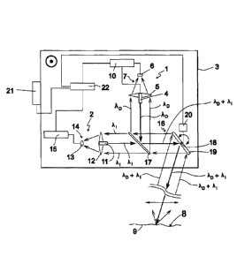
Figure 1 shows a schematic view of one exemplary embodiment of a device
according to the
invention, having a distance image measuring system 1 and an intensity image
measuring system
2. The distance image measuring system 1 and the intensity image measuring
system 2, at least
with their optical components, explained in greater detail below, are situated
in a fixed spatial
3
CA 02936281 2016-07-08
Transtek Document NO. GE0615
WO 2015/113892
PCT/EP2015/051261
relationship with one another on a joint support structure 3 which is
dimensionally stable, even
under harsh environmental conditions.
In this exemplary embodiment, the distance image measuring system 1 has a
distance laser 4,
with a distance wavelength kli), as a distance radiation source for emitting
intensity-modulated
distance measurement radiation. The distance image measuring system 1 is
provided with a
distance detection unit 7 having a distance receiving optical system 5 and a
single-cell distance
detector 6, with which distance measurement radiation that is reflected from a
surface 8 of a test
object 9 is detectable, as explained in greater detail below. In addition, the
distance image
measuring system 1 is equipped with a distance evaluation unit 10 which is
connected to the
distance laser 4 and to the distance detector 6. The distance laser 4 may be
used in a known
manner to generate a distance data value and store it in a location-specific
manner, with
modulation of the distance measurement radiation and detection of the distance
measurement
radiation that is reflected by an area of the surface 8 of the test object 9
which is acted on by
distance measurement radiation, for each area which is acted on by distance
measurement
radiation and which is to be evaluated.
The intensity image measuring system 2 has, as an intensity radiation source
for emitting
intensity measurement radiation of essentially constant intensity, an
intensity laser 11 with an
intensity wavelength ki which is different from the distance wavelength 21,D,
and which has a
beam cross section on the surface 8 of the test object 9 that is different
from the beam cross
section of the distance measurement radiation; the intensity laser is equipped
with an intensity
receiving optical system 12 and an intensity detection unit 14 having a single-
cell intensity
detector 13. The intensity detector 13 is connected to an intensity evaluation
unit 15 of the
intensity image measuring system 2, and is used for measuring the intensities
of intensity
measurement radiation, reflected from the surface 8 of the test object 9, as
intensity data values.
The exemplary embodiment according to Figure 1 also has a radiation deflection
unit 16, which
on the one hand has a stationary dichroitic beam splitter 17 and on the other
hand has a tilting
mirror 19, which as a one-part deflection element is pivotable back and forth
about a pivot axis
4
18 between two boundary positions. The pivot position of the tilting mirror 19
is detectable via a
pivot position sensor 20. In the exemplary embodiment according to Figure 1,
the distance laser
4, the intensity laser 11, and the beam splitter 17 are situated in such a way
that the modulated
distance measurement radiation, with a distance wavelength 2,D, emitted by the
distance laser 4 is
advantageously deflected by 90 degrees by the beam splitter 17, while the
intensity measurement
radiation, with an intensity wavelength
emitted by the intensity laser 11 passes through the
beam splitter 17 essentially with no deflection and is collinearly
superimposed on the distance
measurement radiation. The distance measurement radiation and intensity
measurement
radiation meet in the collinear superimposition on the tilting mirror 19 which
periodically pivots
back and forth between the boundary positions, resulting in a strip-like
illumination of the
surface 8 of the test object 9.
Together with a translation of the support structure 3 and thus of the device
as a whole which
takes place in the direction of the pivot axis 18, as indicated by a motion
symbol illustrated by a
circle with a central dot, the surface 8 of the test object 9 is acted on in
an overall zig-zag manner
by distance measurement radiation and intensity measurement radiation. For
collecting the
translatory motion data of the support structure 3, a motion detection unit 21
is present which,
together with the distance evaluation unit 10, the intensity evaluation unit
15, and the pivot
position sensor 20, is connected to a superimposed image generation unit 22 of
an evaluation
system.
A portion of the radiation, with distance wavelength kr) and intensity
wavelength 2i, reflected
from the surface 8 of the test object 9 is incident on the tilting mirror 19
and is reflected by same
onto the dichroitic beam splitter 17. The portion of the distance measurement
radiation, with
distance wavelength kip, reflected from the surface 8 of the test object 9 is
directed by the
dichroitic beam splitter 17 in the direction of the distance receiving optical
system 5, while the
portion of the intensity measurement radiation, with intensity wavelength i,
reflected by the
surface 8 of the test object 9 passes through the dichroitic beam splitter 17
and is incident on the
intensity receiving optical system 12.
CA 2936281 2021-02-17
CA 02936281 2016-07-08
Transtek Document NO. GE0615
WO 2015/113892
PCT/EP2015/051261
In one exemplary embodiment not illustrated, the radiation deflection unit 16
has a two-part
deflection element in the form of two tilting mirrors which are directly
mechanically rigidly
coupled to one another via a connecting axis. The connecting axis extends in
the direction of the
pivot axis 18. The torsional stiffness and flexural strength of the connecting
axis are established
in such a way that the two tilting mirrors act as an optical unit, resulting
in the same spatial
resolution as with the above-mentioned exemplary embodiment having a single
tilting mirror 19.
The rotation of the tilting mirrors advantageously takes place in the axial
direction of the
connecting axis, which is centrally positioned on the tilting mirrors.
Figure 2 shows a schematic view of the surface 8 of the test object 9, which,
as explained with
regard to Figure 1, is acted on by focused distance measurement radiation with
distance
wavelength 4, and by relatively large-surface intensity measurement radiation
with intensity
wavelength Xi. Figure 2 also illustrates an equidistant sequence of intensity
measuring points 23,
and distance measuring spots 24 having a larger surface compared to the
intensity measuring
points 23. as a detail of an illumination track which results, by way of
example, due to different
capture rates for collecting distance data values and intensity data values
when the tilting mirror
19 pivots in a pivot direction from left to right, depicted by an arrow as
shown in the illustration
according to Figure 2, and the support structure 3 moves in a rotational
direction, depicted by an
upwardly pointing arrow, on the surface 8 of the test object 9.
It is apparent from Figure 2 that the intensity measuring points 23 and the
distance measuring
spots 24 may have different surface areas, and that, for example, the
intensity measuring points
23, due to optimization for the intensity measurement, have a spatial
resolution that is several
times higher than that of the distance measuring spots 24, which have a larger
surface area, as the
result of which the intensity data values obtained from the intensity
measuring points 23 [and]
the distance data values provided by the distance measuring spots 24 may be
refined, and for
example fine structures having different reflectivities may be made
detectable.
6
CA 02936281 2016-07-08
Transtek Document NO. GE0615
WO 2015/113892
PCT/EP2015/051261
Figure 3 shows a schematic view of another exemplary embodiment of a device
according to the
invention, whereby mutually corresponding elements in the exemplary embodiment
according to
Figure 1 and in the exemplary embodiment according to Figure 3 are provided
with the same
reference numerals, and in some cases are not explained in greater detail. The
exemplary
embodiment according to Figure 3 differs from the exemplary embodiment
according to Figure 1
in that a broadband intensity light source 25 is present as the intensity
radiation source, whose
intensity measurement radiation is shapeable into a parallel beam having a
suitable, for example
relatively large and linear, cross section in a broadband intensity wavelength
range AX via a
beam shaping optical system 26 and a collimation optical system 27 of a beam
shaping unit. The
intensity detection unit 14 of the exemplary embodiment according to Figure 3
has an intensity
detector array 28 as a detector array, with a number of detector cells 29,
flatly arranged in two
dimensions, which are connected to the intensity evaluation unit 15 via signal
amplifiers 30.
The radiation deflection unit 16 of the exemplary embodiment according to
Figure 3 is equipped
with a polygon mirror 32 which is rotatable about a rotational axis 31 as a
one-part deflection
element, and which has a number of planar, broadband-reflective mirror
surfaces 33. The
rotational position of the polygon mirror 32 is detectable with a rotational
position sensor 34, and
is suppliable to the superimposed image generation unit 22.
In the exemplary embodiment according to Figure 3, all optical components of
the distance
image measuring system 1 and of the intensity image measuring system 2 arc
arranged in such a
way that for the emitted distance measurement radiation with distance
wavelength 2`,E) and for the
emitted broadband intensity measurement radiation in the intensity wavelength
range AX, and
correspondingly, for the radiation which is reflected from the surface 8 of
the test object 9 and is
to be supplied to the distance detector 6 or to the intensity detector array
28, various mirror
surfaces 33, advantageously next but one mirror surfaces in the rotational
direction, are used.
The arrangement of the optical components of the distance image measuring
system 1 and the
intensity image measuring system 2, and of the polygon mirror 32, is
configured in such a way
that for each rotational position of the polygon mirror 32, an area of the
surface 8 of the test
7
CA 02936281 2016-07-08
Transtek Document NO. GE0615
WO 2015/113892
PCT/EP2015/051261
object 9 is jointly acted on by distance measurement radiation with distance
wavelength XD and
broadband intensity measurement radiation in the intensity wavelength range AL
Thus, due to
the flat arrangement of the detector cells 29 of the intensity detector array
28, a plurality of
intensity measuring points 23 may be detected at any rotational position of
the polygon mirror
32.
In one exemplary embodiment not illustrated, in a modification of the
exemplary embodiment
mentioned above, instead of the polygon mirror 32 a two-part deflection
element is present,
having two polygon mirror segments that are directly mechanically rigidly
coupled to one
another via a central connecting axis. The rotational axis 31 extends through
the connecting
axis, whereby the connecting axis, similarly as for the exemplary embodiment
with the two
tilting mirrors mentioned above, connects the tilting mirror segments to one
another in a torsion-
free manner.
Figure 4 shows a schematic view, corresponding to Figure 2, of a detail of two
illumination
tracks that result when distance measurement radiation with a distance
wavelength XD and
broadband intensity measurement radiation in the intensity wavelength range AX
act on an area
of a surface 8 of a test object 9. Also in the exemplary embodiment according
to Figure 3, as is
apparent from Figure 4, when a large surface is irradiated by the intensity
measurement
radiation, the spatial resolution for the intensity data values is much higher
due to the intensity
measuring points 23 which are relatively small compared to the size of the
distance measuring
spots 24; in the exemplary embodiment according to Figure 3, intensity
measuring points 23 are
present due to providing an intensity detector array 28 with flatly arranged
detector cells 29 for
each illumination track, also in the transverse direction with respect to an
illumination track.
Figure 5 shows a schematic view of another exemplary embodiment of a device
according to the
invention, whereby in the exemplary embodiments according to Figure 1 and
Figure 3 and in the
exemplary embodiment according to Figure 5, mutually corresponding elements
are provided
with the same reference numerals, and in some cases are not explained in
greater detail. In the
exemplary embodiment according to Figure 5, a fiber array 35 provided with a
number of optical
8
CA 02936281 2016-07-08
Transtek Document NO. GE0615
WO 2015/113892
PCT/EP2015/051261
fibers 36 is present as an intensity radiation source. The optical fibers 36
may be acted on by
output radiation having an intensity wavelength k1 from one intensity laser 37
in each case. The
intensity lasers 37 are connected to an intensity laser control unit 38, which
may act on the
intensity lasers 37 with a sequence of control pulses which are offset
relative to one another with
respect to time, so that the fiber array 35 emits a series of pulses of
intensity radiation which are
offset with respect to time and location in a defined manner.
In the exemplary embodiment according to Figure 5, the intensity detection
unit 14 has a single-
cell intensity detector 39 whose output signal is suppliable to a number of
time discrimination
elements 41 via a signal amplifier 40. In the exemplary embodiment according
to Figure 5, the
intensity image measuring system 2 is equipped with a synchronization control
unit 42 which on
the one hand is connected to the intensity laser control unit 38 and the
intensity evaluation unit
15, and on the other hand is connected to the superimposed image generation
unit 22. The time
discrimination elements 41 themselves are connected to the intensity
evaluation unit 15 upon
receipt of a time gate signal, so that, with synchronization by the
synchronization control unit 42,
each time discrimination element 41 emits exactly one intensity signal,
associated with an
intensity laser 37, to the intensity evaluation unit 15, as a result of which
the time offset
information is convertible into location information which is associated with
the corresponding
intensity laser.
The radiation deflection unit 16 in the exemplary embodiment according to
Figure 5 is equipped
with a rotatable polygon mirror 32, corresponding to the exemplary embodiment
according to
Figure 3, whereby in the exemplary embodiment according to Figure 5,
corresponding to the
exemplary embodiment according to Figure 1, the distance measurement radiation
with distance
wavelength 4 is deflectable by a dichroitic transmission beam splitter 43,
while the intensity
measurement radiation with intensity wavelength Xi passes through the
transmission beam
splitter 43 after passing through a collimation optical system 27, and
together with the distance
measurement radiation with distance wavelength 4 acts collinearly on the
mirror surfaces 33 of
the polygon mirror 32. Radiation reflected from a surface 8 of a test object 9
acts on a mirror
surface 33 of the polygon mirror 32 in such a way that it strikes a dichroitic
reception beam
9
CA 02936281 2016-07-08
Transtek Document NO. GE0615
WO 2015/113892
PCT/EP2015/051261
splitter 44. In the exemplary embodiment according to Figure 5, radiation with
distance
wavelength kr) is deflectable onto the distance receiving optical system 5 by
the reception beam
splitter 44, while radiation with intensity wavelength ki passes through the
reception beam
splitter 44 and acts on the intensity receiving optical system 12, which
directs this radiation onto
the intensity detector 39.
It is understood that in addition to a time-division multiplexing method
explained in conjunction
with the exemplary embodiment according to Figure 5, channel separation for
spatial resolution
may also be carried out by frequency-division multiplexing or code-division
multiplexing.