Note: Descriptions are shown in the official language in which they were submitted.
CA 02952146 2016-12-19
-1-
Title: Method and Apparatus for Establishing Fluid Communication Between
Horizontal Wells
FIELD OF THE INVENTION
This invention relates the field of hydrocarbon recovery or the extraction of
oil
and the like from underground reservoirs. In particular this invention relates
to
methods and apparatuses related to in situ extraction of such hydrocarbons and
most
particularly to processes that use a generally horizontal well pair that
includes an
injection well and a production well and requires fluid communication between
the
wells.
BACKGROUND OF THE INVENTION
The efficient extraction of heavy hydrocarbons from underground reservoirs is
challenging. Reservoir conditions are highly variable and pose many unique
challenges for extraction due to unique characteristics of the reservoir.
Presently,
although new discoveries of conventional oil are still being made, there is an
increasing need to produce heavy hydrocarbons. The production of heavy
hydrocarbons can involve considerable technical challenges that have to be
overcome
for these resources to be economically, sustainably, and safely recovered.
A prime example of an abundant but technically difficult resource is found in
the oil sands, for example, in Alberta, Canada. Surface mining is extensively
used,
but can only economically reach a small fraction of the total known resource.
Consequently, efforts have been made to develop in-situ technologies to
recover the other hydrocarbons within the oilsands. These technologies seek to
recover
the hydrocarbons from the surface without significant disturbance of the
surface soil
and the arboreal forest as is required with the surface mining approach.
Current in-
situ technologies being used commercially or are in development can be classed
as
thermal, thermal-solvent and solvent only processes, with this classification
based on
the media or energy source used to mobilize the heavy, or pay hydrocarbons.
CA 02952146 2016-12-19
-2-
Some in-situ technologies use a pair of generally horizontal wells, one
generally above the other, which are sometimes referred to as a well pair. The
upper
well is the injection well used for injecting a working fluid such as water
steam and/or
solvent vapour, and the lower well is the production well used for pay zone
hydrocarbon and working fluid recovery. Recovery processes employing
horizontal
wells in such a vertically paired configuration may rely on gravity drainage,
with the
mobilized liquids draining down into the production well from an extraction
chamber
which is formed around and above the injection well by means of continuous
working
fluid injection.
The start-up phase may be considered to be that part of the extraction process
operation after the wells have been drilled and completed, but before an
extraction
chamber has been developed. In paired horizontal wells of the type used for
gravity
drainage, the wells are typically drilled in proximity to a bottom of a pay
zone
containing hydrocarbons. If the bitumen is immobile at initial reservoir
conditions,
then fluid communication needs to be established between the wells to permit
the
drainage to occur from the formation to the production well. Fluid
communication, in
this sense, means that fluids can travel under the influence of gravity, for
example,
between the upper well and the lower well so that, for example, gases injected
through
the upper injector well can condense and these condensed liquids can flow down
to be
removed through the producer well underneath. If the region between the two
wells
is filled with immobile hydrocarbons drainage is blocked thus limiting
production of
mobile hydrocarbons to the surface. In essence then, fluid communication
involves
removing the immobile, or near immobile hydrocarbons from between the well
pair in
a manlier that permits fluids to easily drain down to the production well. If
the liquid
drainage is obstructed, then the extraction chamber will just fill up with
liquid and the
ability to deliver working fluid and/or heat to the reservoir is impaired.
In the SAGD process, steam is typically circulated in the well bores to
preheat
the surrounding reservoir. By means of such heat the hydrocarbons are rendered
somewhat mobile and can be removed from between the well pair. This approach
has
CA 02952146 2016-12-19
-3-
some disadvantages for solvent based processes because it introduces a lot of
water
into the formation and water can be an effective barrier to solvents, and thus
impair
the contact between solvent and the bitumen. Further, this would require both
solvent
and steam processing surface facilities which duplicates capital costs.
Canadian Patent Applications 2,691,889 and 2,730,680 relate to solvent
extraction processes in which a solvent gas is circulated in both the
production well
and the injection well to warm the near well bore area. However, these patent
applications teach the use of a solvent gas at a temperature above its
critical
temperature. The problem with using gas to establish communication between the
well pair is its relatively low sensible heat content; consequently, the start-
up process
will take a long time to mobilize the pay hydrocarbons between the well pair
and
require high gas flow rates and pressure drops to establish the desired
temperature rise
between the two wells even though a high temperature is being used. High
pressures
can lead to solvent leak off and loss. Further, as taught in these
applications, the high
heat creates a de-asphalting effect that can lead to deposits. Such deposits,
if located
between the upper and the lower well can cause a reduction in the formation
permeability between the wells, leading to plugging or poor drainage. Lastly,
a high
heat, high pressure process will likely lead to spot breakthroughs between the
well pair
or short circuiting, which will establish some, but only very limited,
localized
hydraulic drainage between the wells. What is desired is a start-up process
that will
generally mobilize and remove substantially all of the pay hydrocarbon from
the entire
length of the zone between the well bores thereby permitting the formation to
be freely
draining for the working fluids without leaving damaging asphaltene deposits
behind
in the reservoir region used for well drainage. An improved start-up procedure
is
required.
SUMMARY OF THE INVENTION
What is desired therefore is a start-up method to establish fluid
communication
by forming a drainage zone between a pair of horizontal wells that are to be
used in
CA 02952146 2016-12-19
-4-
gravity drainage thermal, thermal-solvent, and solvent based extraction
processes.
Thus, for any process which can create mobile fluids within the formation good
drainage rates will lead to good production rates. The preferred start-up
method should
mobilize and remove the pay hydrocarbon in the inter well bore zone without
introducing excess water into the formation or causing other formation damage
such
as the deposition of asphaltenes. The start-up method should be reasonably
quick and
reliable to establish good communication along the length of the well pair
with a
minimum of blocked or impervious regions. The total time for the start-up
process
should be minimized, be simple and robust, and at the completion of the start-
up
process, the in situ conditions should be compatible with the desired
subsequent
working fluid injection conditions. In particular, for example for a heated
solvent
process, the temperature of the formation between the well bores should be
compatible
with the operating temperature for the follow on condensing solvent process,
for a
smooth hand off between start-up and extraction.
According to the present invention these and other objectives can be met by
using a multi-step start-up procedure. A first step is to deliver heat into
each of the
well bores. This can be readily achieved by circulating start-up liquid such
as a hot
hydrocarbon fluid into the toe of the well and back along the annulus or vice
versa into
the heel and back down the annulus or by energizing a heating element placed
in the
well bore or by some combination of both. Heat supplied to each of the well
bores
will be conducted outward from the well bore and will eventually raise the
temperature
of the region between the well bores. The start-up procedure involves
optionally
preheating the near well bore area for example, using a resistance electrical
heating
device inserted into each of the well bores. Next, a positive pressure
differential can
be applied between the injection and production wells to displace the start-up
liquid
into the pay hydrocarbon, to encourage further mixing, warming, and
displacement
into the one of the production and injection wells where it can be
subsequently
removed by the recirculating start-up liquid. The temperature may be reduced
or
increased during this stage and recirculation from both wells is carried on
until the pay
CA 02952146 2016-12-19
-5-
hydrocarbon starts to become reasonably mobile, as evidenced by the amount of
pay
hydrocarbon content produced to the surface in conjunction with the re-
circulating
liquids. At an appropriate time, the production well is put into production,
with
artificial lift if required, and the recirculation rate in the injection well
is gradually
reduced in favour of a displacement between the upper injection well to the
lower
production well. This displacement is carried on until the mobilized pay
hydrocarbon
is largely removed from between the wells and clear communication is
established by
the start-up liquid. Communication completeness is determined by the amount of
pay
hydrocarbon in the recirculation fluid at the production well. The
mobilization and
removal of the inter-well bore pay hydrocarbon is accomplished whilst
substantially
avoiding the creation of potentially harmful asphaltene deposits in the near
well bore
region since it is a displacement rather than a solvent mobilization. More
specifically,
this goal is achieved by avoiding the use of known deasphalting solvents such
as
propane, butane, pentane and others that cause asphaltene precipitation until
after the
start-up phase is completed. During a following condensing solvent process for
example, where de-asphalting may occur, such de-asphalting will occur at the
extraction chamber perimeter, will be widely disbursed and will not adversely
affect
fluid drainage properties to the production well.
According to one aspect, the present invention provides an apparatus for
applying a start-up method to an inter well bore region between two vertically
displaced horizontal wells, said apparatus comprising:
a source of non deasphalting start-up fluid above grade;
a heater for heating said start-up fluid;
a well head connection from said source to each of said two vertically
displaced
horizontal wells;
a fluid delivery and removal system connected to said well head to permit said
start-up fluid to be circulated along each of said two vertically displaced
horizontal
wells;
one or more circulating pumps for circulating said start-up fluid from said
CA 02952146 2016-12-19
-6-
source through said heater down into said formation along each of said
vertically
displaced horizontal wells and then back up to the surface;
a conditioner located above grade to remove solids and water if necessary from
said returned start-up fluid, and
sensors to measure one or more of a temperature, a viscosity, and a
composition of said start-up fluid which is returned to the surface.
BRIEF DESCRIPTION OF THE DRAWINGS
Reference will now be made, by way of example only, to preferred
embodiments of the invention in which:
Figure 1 is an illustration of a horizontal well pair located within a pay
zone of
an underground formation;
Figure 2 is a graph showing the change in viscosity of sample pay hydrocarbon
such as bitumen for different temperatures and blends with a liquid
hydrocarbon such
as synthetic crude oil (SCO);
Figure 3 is a schematic showing the different stages of a start-up procedure
according to the present invention;
Figure 4a is a diagram indicating the well bore and midline temperatures over
time for a typical well pair for a given initial electrical resistance pre-
heating period;
Figure 4b is a diagram indicating the well bore and midline temperatures over
time for a typical well pair for a given initial start-up liquid temperature
and flow rate;
Figure 5 is a graph illustrating the temperature at the well bore midline and
the amount of heat energy absorbed by the reservoir over a treatment period
for a
treatment according to the present invention;
Figure 6 is a chart illustrating the effect of well spacing of the well pair
on the
timing of the start-up phase according to the present invention;
Figure 7 is a schematic view of the bitumen phase on one side and the
temperature profile on the other side of at four different times during the
start-up
procedure according to the present invention;
CA 02952146 2016-12-19
-7-
Figure 8 shows the effect of spacing between the well pair on the drainage
time
according to the present invention; and
Figure 9 shows the effect of changing the pressure differential on the
drainage
time according to the present invention.
DETAILED DESCRIPTION OF THE PREFERRED EMBODIMENTS
Figure 1 is a schematic view of a generally horizontal well pair with an upper
well 10 and a lower well 12 that are separated by a well spacing 14. Midway
between
the wells 10 and 12 is a mid or centerline 16. The wells 10, 12 are located
within an
underground formation 18 which includes a pay hydrocarbon zone 20, with an
overburden 19 and an underburden 21. The well pair 10, 12 are positioned
towards
the bottom of the pay hydrocarbon zone 20 in accordance with a conventional
positioning of the well pair for gravity drainage. The preferred type of pay
zone is a
heavy hydrocarbon pay zone such as may be found in the oilsands of Alberta,
Canada.
Although the wells are shown with slanted risers 22,24, and horizontal casings
26, 28, it will be appreciated by those skilled in the art that these are
illustrations only
and that in practice the angle of the wells might vary considerably from this.
Thus, in
this specification, the terms generally horizontal and generally vertical are
used to
comprehend the field variations that might be encountered from horizontal and
vertical. Further, in this specification, the term near well bore area means
an area
surrounding a well bore in cross section. As well, the term inter well bore
area means
the space between the well pair.
The present invention comprehends providing the well bores with a pre heating
phase which may be electrical resistance heating and or a fluid delivery
system to
provide a heated start-up liquid to the wells in accordance with a preferred
method as
described below. In one form of the invention, the resistance heating system
includes
long electrical resistance well bore heaters 27, 29 that extend along the
length of each
of the wells having electric power lines 31, 33 which extend to the surface
and are
connected to a power source. While this is one form of pre-heating device it
will be
CA 02952146 2016-12-19
-8-
understood that the present invention comprehends other forms of in situ or
downhole
heater as well. What is desired is some form of downhole heat that can be used
after
the wells are completed, but before the surface facilities are ready to
circulate the start-
up fluid.
In Figure 1, the fluid delivery system includes narrow diameter tubes 30, 32,
for example 3 Y2-inch coil tubing, which is fed down the riser portion of the
well and
then fed out towards the toe 34, 36 of each well 10, 12. A second narrow
diameter
tube 38, 40, such as the 3Y2 inch coil tubing, is also fed down the riser
portion of each
well, but preferably extends only to about a heel 39, 42 of each well 10, 12.
Each of
the narrow diameter tubes 30, 32, 38 and 40 are connected to appropriate above-
grade
pumps and heaters to allow a circulation of liquid down to the toe, back along
the
casing and then up through the tubes 38, 40 to the surface again in each well
10, 12 as
shown by arrows 44. Although this is shown as extending from the toe and the
heel,
the present invention comprehends ending the narrow diameter tubes
intermediate the
ends depending upon the circumstances.
In the most preferred embodiment of the invention, the start-up liquid is a
liquid hydrocarbon that is heated above-grade in an appropriate heat exchanger
(not
shown) before being circulated through the wells 10, 12, by, for example, a
pump.
Accordingly, the present invention provides a liquid circulation system for
start-up,
which permits the start-up liquid to be heated above and / or below grade,
pumped
down the tubes 34, 36 of each well and out to the toe, where it is released
into an
annulus formed between the narrow diameter tubing and the well casing. Then
the
fluid is drawn back along the casing towards the heel, where it enters the
second tubes
38,40, and from there it is brought or pumped up to the surface. The present
invention
comprehends that the circulation direction could be reversed. At the surface
the start-
up liquid can be conditioned to remove solids and water if necessary, reheated
and
then re-circulated back into the wells as described above. Placing the start-
up fluid
well inflow end at the toe or the heel establishes a countercurrent heat
exchange,
between the tubing and the annulus. While countercurrent heat exchange is not
optimal
CA 02952146 2016-12-19
-9-
and initially produces large thermal gradients along the well bore,
calculations show
that for the preferred embodiment of the invention, within a week, the counter-
current
temperature gradient flattens out and the well bore is effectively isothermal,
permitting
most of the heat in the start-up liquid to be delivered to the formation in
the near well
bore area through conduction.
The preferred method of the present invention is a multiple step process, as
described in more detail below. In an optional first step or phase, which may
or may
not be appropriate in all circumstances a downhole heat source, such a
downhole
heater, for example, an electrical resistance heating device can be placed in
each of the
well bores. Heat from the downhole heater is delivered to the well bore and in
the case
of a resistance electrical heater is transferred into the reservoir formation
by
conduction. Electrical power is supplied to the resistance heating device
located above
grade through an appropriate connection to an electrical power supply. This is
considered a pre-heating step or phase and is continued until a desired amount
of heat
is delivered to the reservoir. Such a preheating step may reduce the time
required to
transfer heat through start-up fluid circulation alone.
As for the start-up fluid, assuming that no down hole heater has been used, in
the next step the start-up liquid is heated above grade, and then simply
circulated
within each well for enough time to further increase the reservoir temperature
in the
region surrounding the well bores or the near well bore area. As the start-up
liquid's
heat is transferred to the formation through conduction, the temperature will
gradually
rise in the near well bore region in a circular or radial pattern around each
well bore.
The heat and volume lost from the circulating start-up liquid is made up by a
combination of reheating and the addition of fresh, hot start-up liquid at the
surface.
It will be appreciated that the preferred start-up liquid is one that is
compatible with
the surface facilities for the extraction process. Thus, in the case of a
process that uses
a working fluid of a condensing solvent, the preferred start-up liquid is a
form of liquid
hydrocarbon. Many different start-up liquids are comprehended by the present
invention, provided they meet with certain initial criteria. Most preferably,
the start-
CA 02952146 2016-12-19
-10-
up liquid is hydrocarbon-based so as to avoid using or introducing water into
the
formation. Fluids such as SCO, diesel fuel and other refined or upgraded
products are
suitable. What is most preferred is a liquid that does not cause de-
asphalting, will
remain a liquid in the temperature and pressure ranges used in the start-up
process of
the present invention, and which is generally available in the local area.
Liquids are
preferred over gases due to their greater effectiveness in delivering heat to
the reservoir
and their greater ability to sweep out or displace in situ hydrocarbons
located between
the well pair.
Of course, the rate of heating will depend on a number of factors, including
the
rate of flow and initial temperature of the start-up liquid and the initial
temperature of
the reservoir. According to well understood engineering principles, the
greater the
temperature difference between the start-up liquid and the reservoir, the more
rapid
the heating of the reservoir will be. However, there may be temperature and
pressure
limits imposed by the conditions present in the reservoir or the desired start-
up
conditions that must be considered in defining the operating conditions for
temperature
and pressure. In the event that an initial pre-heat is applied with a downhole
heater,
the start-up fluid must be warmer that the near well bore temperature to add
heat to the
formation. However, the start-up fluid is also responsible for hydromechanical
effects
as set out below, namely the displacement of the inter well bore pay
hydrocarbons
even if the heating has been adequately done by the electrical heat.
Figure 2 shows a graph that illustrates the calculated change in viscosity of
representative bitumen with both change in temperature and change in
concentration
in a preferred hydrocarbon start-up liquid, specifically SCO, in a bitumen/SCO
blend.
The curve 50 is the change in viscosity curve of pure representative bitumen.
Below
that are curves 52, 54, 56, 58 and 60, which represent 90% bitumen/10% SCO to
10%
bitumen/90% SCO in changes of 20% on a per line basis. The line 62 represents
the
change in viscosity for SCO over a range of temperatures. This graph
illustrates that
there are significant changes in viscosity for the bitumen with both a
temperature
change and a change in SCO concentration. As can now be understood, the
present
CA 02952146 2016-12-19
-11-
invention seeks to take advantage of two ways to reduce viscosity of the
bitumen in
the inter-well bore zone i.e. by both warming and liquid dilution. In some
cases, it
may be appropriate to clean out the wells before commencing with the start-up
method
of the present invention. The clean out of the wells is for the purpose of
removing any
material that would impede the easy flow of fluids through the well, such as
leftover
drilling mud or the like, as well as removing any excess free water that might
be
present. A nitrogen or other gas huff-and-puff optionally is comprehended by
the
present invention. In this sense a huff-and-puff pretreatment step involves
injecting a
gas, up to a certain pressure, and then releasing the pressure and removing
the gas from
the area in which it was applied. In any such clean out preconditioning step,
it is
important not to use so much pressure as to overpressure the formation. Thus,
it is
preferred to keep the "huff" pressure well below a formation fracture pressure
and
most preferably below reservoir pressure during the huff and puff step. By
being
below the native reservoir pressure it may be possible to prevent a loss of
the
pressurized gas to the formation. The clean out gas can also be circulated
through the
well tubes to the toes, then into the annulus and then drawn out again through
the well
tubes located at the heels as described previously to clean the tubes out if
needed or
desired.
Once the clean out step has been completed (if the same is necessary or
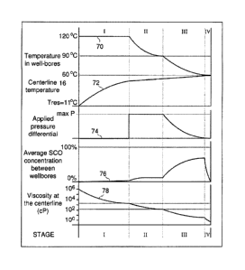
advisable), the start-up method can commence. Figure 3 shows a schematic of a
preferred form of the present invention, which has four main stages identified
by
numerals I, II, III and IV across the top and, for ease of reference, the
bottom of the
Figure 3. Plots are provided for the changes in various parameters during each
of the
start-up phases. At the top, line 70 is a plot of the temperature of the well
bores during
the four phases for the invention implemented in an oilsands reservoir as
found in
Alberta, Canada. Below it is a plot 72 of the temperature of the centerline
between the
two wells for the like implementation, and Line 74 is a plot of the applied
pressure
differential between the two wells. The plot 76 identifies the average
relative pay
hydrocarbon concentration that arises between the well bores in the zone to be
cleared.
CA 02952146 2016-12-19
-12-
The plot 78 shows the average relative change in the pay hydrocarbon viscosity
at the
well-pair centerline during the start-up phases. While these values are
suitable for the
representative bitumen used in this example, the actual values may vary for
other
bitumen or pay hydrocarbon deposits.
The present invention comprehends a further pretreatment step using a means
of delivering heat directly to the formation through a downhole heater such as
an
electrical downhole heater. In a preferred embodiment the heater is in the
form of a
long heater element that can run the length of the wells. As can be seen from
the
Figure 3, Stage I involves raising the temperature of the near to the inter
well bore
area. This may be done by a downhole heater by circulating hot start-up fluid
or a
combination of both. Regardless of the source of the heating what is desired
is to
provide an even heat distribution along the length of wells to help warm the
inter well
hydrocarbons. In the event downhole heaters are used, one form is to use long
heating
cables that run the length of the wells to provide heat distribution along the
length. As
the wells are typically drilled prior to the construction of the above grade
facilities, the
use of a downhole heater with no fluid circulation may enable well bore
heating to
start before the plant might otherwise be available to begin the start-up
fluid circulation
phase, thus beginning pre-heating early and potentially shortening the start-
up time. It
is desirable to top up the well bore with an appropriate fluid like SCO to
enhance the
uniform transfer of electrical heat to the reservoir and avoid the potential
of
overheating during the downhole heater heating step. This also encourages some
near
well bore dilution of the pay hydrocarbon which is required for viscosity
reduction as
explained in more detail below.
Another option to deliver heat to the formation in the first stage of the
present
invention is the circulation of heated liquid, which will further distribute
the heat along
the well length and also carry heat to the formation without asphaltene
precipitation.
As can be seen by the temperature graph of the centerline temperature 72, over
this
phase, the temperature between the wells rises from a native reservoir
temperature to
anywhere between 40 C and 70 C, most preferably between about 40 C to 50 C. As
CA 02952146 2016-12-19
-13-
shown by the plot line 78, the application of heat will reduce the bitumen
viscosity by
about 99%. This is accomplished primarily through the temperature conduction
as
there is no appreciable mixing of the start-up liquid and the pay hydrocarbon
during
this phase.
The present invention comprehends providing heat by circulating a heated
start-up fluid through each of the producer and the injector wells. Assuming a
500
meter well and a 31/2-inch coiled tubing, the start-up liquid can be
circulated at a rate
of 5000 barrels per day (bpd) per well and an initial temperature of anywhere
between
30 C to 300 C, but in this example at about 120 C. In this example, the
average
spacing between the horizontal wells is assumed to be 5.5 meters. Using these
values,
the temperature increase in the near-well bore area as a function of time can
be
calculated. The length of time required to complete this phase is estimated to
be about
two to six months, with about three months being average, but the time being
dependent on the amount of downhole heater pre-heating the start-up fluid
temperature, the recirculation flow rate, the length of the wells and the
reservoir
characteristics. These start-up times are examples of what might be suitable,
but other
start-up times are also comprehended by the present invention. In choosing the
appropriate start-up fluid and temperature, it is preferable to avoid de-
asphalting
conditions in the inter well bore area that can damage the porosity of the
reservoir
formation and inhibit the ability to establish communication between the well
pair.
It is also highly undesirable to inject hot hydrocarbon based fluid at
pressures
well above native reservoir pressures because this can lead to loss of
confinement and
the start-up fluid can be lost from the inter well bore region. This
displacement can be
avoided or mitigated by the use of artificial lift, so that the downhole
circulating
pressure is maintained at or perhaps even below the native reservoir pressure.
During
the next step, the temperature of the start-up liquid is adjusted to achieve
desired
operating temperatures for a subsequent formation treatment while still
circulating as
per Stage I. The main event of phase II is the application of a pressure
differential
between the two well bores. Most preferably, the pressure is applied from the
upper
CA 02952146 2016-12-19
-14-
well to the lower well, so that the pay hydrocarbon flows downward assisted by
such
pressure differential and the viscosity reduction arising from one or both of
a
temperature change and dilution. A pressure applied from the lower well to the
upper
well is also comprehended by this invention. The pressure difference may be
applied
5 by increasing the pressure in one well, reducing the pressure in the
other well, or both.
Adjusting the pressure in both wells allows for the optimization of the
pressure
differential between the wells without exceeding a desired maximum pressure in
the
reservoir formation. The benefits of the applied pressure differential can now
be better
understood, as, for example, as pressure is applied to the upper well, it will
displace
10 the start-up fluid outwardly. In turn, the start-up liquid will displace
the pay
hydrocarbon downwardly into a warmer region of the lower well. This
displacement
further encourages the dissolution and warming of the pay hydrocarbon so as to
reduce
its viscosity and enhance the ability to displace it from between the well
pair.
As can be seen from the plot line 76 in Figure 3, the increased start-up fluid
15 concentration in the pay hydrocarbon and the increased temperature have
the effect of
further lowering the pay hydrocarbon viscosity, as shown by the plot 78. Most
preferably, this phase is completed with little or no further addition of
start-up liquid.
This means that the circulating fluid reaching the surface trends towards an
increasing
concentration of pay hydrocarbon content in the start-up fluid. As can now be
20 appreciated, the rising content of pay hydrocarbon in the circulating
start-up fluid in
combination with a decreasing temperature increases the viscosity of the start-
up fluid
and helps to limit the amount of fluid flowing between the two horizontal
wells, while
still allowing a pressure difference to be sustained. In this manner, the
present
invention is better able to hydraulically sweep out pay hydrocarbons between
the
25 wells. Further, the amount of pay hydrocarbon present in the start-up
liquid can be
monitored and used as a proxy for how close the process is to establishing
communication along the full length of the well pairs. The present invention
contemplates that there will be a non-uniform flow rate of start-up fluid
between the
wells at various locations along its length. However, by continuing the
process of re-
,
CA 02952146 2016-12-19
-15-
circulating the start-up fluid, with the application of moderate pressures
over a
sufficiently long enough time frame, the present invention can provide for the
gentle
physical displacement and removal of the pay hydrocarbon from the inter-well
bore
area without asphaltene deposition.
Now the procedure enters the next stage III of the present invention. As more
and more of the inter-well bore pay hydrocarbon is progressively mobilized and
displaced, the circulating pumps become rate limited and thus the ability to
apply a
pressure differential may be reduced. Again, it is desirable to continue to
adjust the
temperature of the circulating fluid gradually so as to permit the formation
to assume
the design operating temperature for the extraction process that follows. This
can
involve a reduction in start-up fluid temperature. Also, the viscosity of the
circulating
fluids may be increased by allowing a greater pay hydrocarbons concentration
or a
lower temperature or both. A higher viscosity allows a high pressure
differential and
a more effective sweep of pay hydrocarbons from the inter well bore region. In
the
case of a following solvent based extraction process, the design operating
temperature
may generally be between 20 C to 70 C, most preferably 40 C to 60 C, but
again
dependent on the reservoir conditions. Ideally, the heated start-up liquid-pay
hydrocarbon fluid mixture that is circulating is almost at the same
temperature as the
centerline by the end of this phase. However, due to the mixing and
mobilization of
the start-up liquid and the pay hydrocarbon there is a higher concentration of
start-up
fluid between the well bores. As can be seen from the plot 78, the viscosity
of the
centerline is still further reduced during this next stage as the centerline
fluid (bitumen)
is progressively displaced with the bitumen start-up fluid blend. The
application of a
sustained pressure differential over a sufficiently long time ensures almost
complete
mobilization of the pay hydrocarbon in the inter well bore region. The
completion of
this stage III can be predicted by numerical simulation, and/or confirmed by a
variety
of physical measurements, such as pressure drop, shut in well bore temperature
profiles, fluid properties, tracer residence time analysis, etc.
CA 02952146 2016-12-19
-16-
The last stage is stage IV, and it consists of preparing the chamber for
production. At the start of this stage, the centerline temperature is about 60
C or
whatever other temperature is desired to achieve optimum temperature for the
start of
the working fluid injection and the fluid between the two well bores is a
diluted
mixture of pay hydrocarbon and start-up fluid with a viscosity between 10 cP
and
1000cP.
At this point, the fluid recirculation into the wells is stopped and the
mobilized
fluid is drained. A means for lifiing the liquids out of the formation may be
required,
such as by using an electrical submersible pump on the production well. The
pump is
operated for long enough to permit all of the fluid to drain out of the near-
well bore
area so it can be replaced by the working fluid and to thereby establish good
hydraulic
drainage along the length of the wells. This is shown as a dramatic reduction
in start-
up liquid concentration between the wells, and a temperature at the centerline
which
approaches the temperature of the well bores indicating an even temperature
distribution in within the inter-well bore region. In some cases it may be
necessary to
provide working fluid vapour to the chamber to provide voidage replacement as
the
mobilized pay hydrocarbon is drained. In other cases, the voidage volume may
be
filled from dissolved gases that may naturally evolve from the pay
hydrocarbon. If it
is necessary to supply some working fluid then a small amount of, for example,
solvent
vapour can be injected into the well provide some vapour pressure support
without
reaching a pressure that causes condensing conditions so as to minimize the
risk of
deasphalting the mobilized pay hydrocarbon between the well bores.
When the mobilized pay hydrocarbon is largely drained from the well bore
region then the injection of working fluid can now begin. The working fluid is
injected
from the injection well into the heated, drained chamber and it traverses the
chamber
and condenses on the cooler extraction interface, located at the periphery of
the
extraction chamber, where it releases its heat and reduces the viscosity of
the pay
hydrocarbon so that the blend can drain by gravity down to the production
well.
Achieving this condition is mostly a matter of increasing the working fluid
injection
CA 02952146 2016-12-19
-17-
rate so that the chamber pressure is such that condensing conditions are
achieved.
From this point on, normal gravity drainage production can proceed. The start-
up
procedure thus displaces pay hydrocarbon from the inter well bore area through
the
combined effects of dilution with start-up fluid and raises the temperature.
Although
60 C is used in the example, it will be understood by those skilled in the
art that any
convenient, condensing vapour temperature could be selected based on the
working
fluid being used. What is desired is to have the temperature of the near-well
bore area
compatible with the desired operating conditions once the start-up process is
complete.
It can now be understood that the working fluid may result in the deposit of
immobile asphaltenes with the formation. However, as the start-up stages have
displaced the pay hydrocarbons from the inter and near well bore area, these
asphaltenes will be located well away from the well bores, and will be
dispersed
through the formation. Thus, it can be appreciated that the present invention
is
intended to reduce the production of the asphaltenes at a location where they
could
substantially interfere with the hydraulic drainage properties of the
formation in the
vicinity of the production well.
Certain features of the present invention can now be appreciated. For example,
it can be now understood that the present invention warms, dilutes and drains
the pay
hydrocarbon between a pair of generally horizontal wells without significant
precipitation of asphaltenes in the close proximity of the wells. This is
intended to
ensure good flowability and drainage of the working fluid and produced fluid
both
around the wells and between the wells. The pressure differential is applied
between
the wells to encourage mixing, for better heat transfer, and to mobilize the
pay
hydrocarbon from the well bore area into one of the wells so that it can be
removed
from the reservoir. The start-up liquid has an ability to deliver heat
efficiently to the
formation to encourage a reduction in the viscosity of the in situ pay
hydrocarbon.
Using the toe delivery tube and the heel removal tube in each horizontal well
encourages the flow of the start-up liquid along the length of the wells to
even out the
heat distribution during the process along the full length of the horizontal
wells. Figure
CA 02952146 2016-12-19
-18-
4 shows the well bore and center line temperatures, after 3 days, 10 days, 90
days and
steady state, for wells with a working fluid supply temperature of 120 C for a
500
meter well pair and a 5000 bpd circulation rate. As shown, the temperature in
the
wells after one week is about 105 C and it is estimated that the temperatures
reach a
steady state when the heel is about 110 C and the toe is about 115 C.
The centerline temperature profile (i.e. at the midline 16 of figure 1) is
also
shown at different times during the start-up process (in this case without a
downhole
heater pre-heating step). In this same example, the well temperatures are
shown at the
start, after ten days, after 30 days, after 80 days and after 115 days. As can
be seen,
the temperature profiles at the centerline are quite uniform despite the large
increase
in the well bore temperature. This is because it takes time for the heat to be
conducted
out to the mid-point between the well pair.
Figure 5 is a graph of the total heat supplied to the area and the temperature
history over time for this example. The plot line 80 shows the change in
temperature
and the plot line 82 shows the rate of heat input in kW. As the reservoir
surrounding
the wells gets warmer, the rate of heat transferred by the start-up fluid gets
smaller due
to a smaller temperature difference. As shown, after one week the rate of heat
input
into the ground is about 500kW per well pair, after two weeks it might drop to
about
400kW and at the end of the period it has dropped to 300kW.
Figure 6 shows the estimated effect of start-up fluid temperature on the warm-
up period. According to the present invention, the warm-up period can be
reduced by
supplying the start-up fluid at a temperature of 140 C as compared to 120 C,
and
reduced even further by supplying start-up fluid at 170 C. The reduction in
start-up
time for a well spacing of 5.5 meters on average is estimated to be to three
months for
an operating temperature of 140 C as compared to well over four months for a
120 C
operating temperature, and two months for 170 C, as shown by plot line 90.
Plot lines
92 and 94 show the start-up time for a well pair spacing of 4.5 meters and 6
meters
respectively and various operating temperatures. It will be understood,
however, that
the end of the start-up procedure defines a starting temperature for the
beginning of
CA 02952146 2016-12-19
-19-
extraction. The higher the temperature of the extraction process, which in
some cases
is controlled by selecting an operating pressure and thereby defining a
condensation
temperature, the greater the overall energy requirement for the extraction.
Thus, the
present invention is intended to warm the formation up in the near-well bore
area to a
temperature that is compatible with the extraction process which follows. In a
preferred embodiment the hand-off temperature is equal to the extraction
temperature,
but the present invention comprehends that these two temperatures may also be
different, depending upon the extraction process.
Figures 7a to 7d illustrate more clearly the effect on the near- and inter-
well
bore areas of the start-up method according to one aspect of the present
invention.
These graphs depict temperature profiles overtime, and are estimated at 30,
60, 85 and
93 days for a test case. The test case is a well of 500 meters in length, with
a start-up
liquid temperature of 120 C, a well separation distance of 5.5 meters, and a
differential
pressure of 2MPa. On the left hand side of each drawing is the pay hydrocarbon
swept
areas and on the right hand side is shown the estimated temperature contours
100. As
can be seen by the thermal contours, the temperature wave gradually penetrates
outward, further away from the wells 10, 12 in a radial pattern. On the other
half of
the figures, it can be seen that the pay hydrocarbon is gradually swept out of
the inter-
well bore region over time with the expansion of swept area, shown as 102,
104, and
106. The exact time required to displace the pay hydrocarbon and complete the
start-
up process will vary from reservoir to reservoir and will vary along the wells
depending on the spacing of the horizontal wells at a particular location but
the
foregoing illustrates the effect of the preferred invention on the near-well
bore region.
For ease of illustration, the swept areas are shown for one half of the well
bores 10,
12, although it will be understood by those skilled in the art that the swept
area will be
symmetrically extended on both sides of each of the wells 10, 12.
Figure 8 shows the effect on the sweeping time of the pay hydrocarbon of well
pair separation and start-up fluid operating temperature. The y-axis is
sweeping time
in days and the x-axis is the temperature of the start-up fluid. The plot
lines 110, 112
CA 02952146 2016-12-19
-20-
and 114 show that the closer the well pair 10, 12 is together, and the higher
the applied
temperature, the quicker the sweeping time for this representative example.
Figure 9
shows the effect on sweeping time of start-up fluid temperature and applied
pressure.
In this figure, the y-axis is sweeping time in days and the x-axis is the
temperature of
the start-up fluid. Additionally, the plot lines 116, 118 and 120 are three
different
pressure differentials applied between the wells 10, 12. As can now be
appreciated,
the present start-up method can be varied to be made quicker or slower as
needed to
suit local reservoir conditions and operating requirements. Generally, the
greater the
temperature of the start-up fluid, the faster the displacement can occur,
sweeping out
the pay hydrocarbons. Generally, the closer the well spacing, the faster the
pay
hydrocarbon is removed from the inter-well bore area. Generally, the higher
the
pressure applied between the wells, the faster the desired completion of
sweeping the
inter-well bore region of pay hydrocarbon. However, the individual conditions
of the
reservoir may provide upper limits to each of these parameters. Closer well
spacing
requires good inflow control into the production well to avoid flooding the
injector
well with liquids. Higher pressure differentials require good reservoir
integrity to
avoid pushing the start-up fluid out, away from the inter-well bore area
through high
permeability routes.
As can now be appreciated, the present invention comprehends using certain
equipment to implement the preferred start-up process. For example, above
grade
there is a source of liquid start-up fluid, most preferably a non-asphaltene
hydrocarbon
that can be heated by a heater to a predetermined temperature. Next, there
needs to be
a pump and a wellhead connection, to permit the heated hydrocarbons to be
circulated
through the wells. If the reservoir integrity is sufficient, that the pump
pressure can
be used to also pump the fluids back out of the well, then that is preferred.
However,
the present invention also comprehends that it may be necessary to use well
heel
pumps to pump the liquids back up to the surface as a means to reduce the
reservoir
pressure to match reservoir containment conditions. Such well heel pumps might
be
any form of suitable pumps for artificial lift such as electrical submersible
pumps.
CA 02952146 2016-12-19
-21-
This adds expense and complexity and thus is less preferred except when to do
otherwise would invite a loss of liquids owing to a lack of reservoir
integrity.
The present invention also comprehends using temperature and pressure
sensors and the like to instrument the wells during the start-up process to
provide
monitoring of the progress of the start-up through the different phases. The
present
invention also comprehends using temperature and pressure sensors and the like
to
instrument observation wells in order to monitor the start-up process.
Sampling
facilities located above grade are also required to monitor the pay
hydrocarbon content
of the circulating fluid.
The present invention also comprehends the use of a downhole heat source
such as an electrical resistance heater to use in delivering heat as an
initial option phase
of the start-up process, as noted above.
As can now be appreciated the present invention provides for a warming of the
pay hydrocarbon in the near well bore area by contact with a warm start-up
liquid, for
the purpose of reducing the viscosity of the pay hydrocarbon. In this sense,
warm
means moderate temperatures as opposed to the high temperature steam at
typical
reservoir pressures of 1 MPa or higher. Further, the start-up liquid is
dissolved into
and mixed with the pay hydrocarbon to further reduce the viscosity without
being in
sufficient quantity or kind that substantive asphaltenes are deposited in the
inter well
bore region. Essentially the present invention is aimed at mobilizing and then
removing the pay hydrocarbon, largely by hydraulically sweeping or displacing
the
same, from the near-well bore area to establish a working fluid injection and
extraction
chamber. At the end of the start-up process, the extracted zone is at or near
to the
desired temperature for the extraction process that follows. The start-up
process has
been carried out in the absence of any water injection. Also, any residual
water in the
reservoir that may have been turned into steam by the warm start-up liquid,
will re-
condense and be removed from the near-well bore region as the liquids are
removed
in the start-up process. Once extraction commences, the asphaltene deposits
that may
occur will be formed at a location distant to the near-well bore region at the
extraction
CA 02952146 2016-12-19
-22-
interface and thus will not impede fluid flow in the near well bore region.
Further, the
start-up liquid is preferably compatible with the surface facility that is
located above
the reservoir for the purpose of working fluid injection and pay hydrocarbon
production. Furthermore, the displacement from injector to producer could be
reversed
and the circulating and displacement fluid could be injected at other
locations besides
the toe, and withdrawn at other locations besides the heel, as needed.
While the foregoing describes preferred embodiments of the present invention,
it will be understood by those skilled in the art that various modifications
and
alterations are possible without departing from the broad spirit of the
invention as
defined in the attached claims. While some of these variations have been
discussed
above, others will be apparent to those skilled in the art. All such
variations and
modifications are comprehended by the present specification.