Note: Descriptions are shown in the official language in which they were submitted.
84024929
BREAKING APART A PLATFORM UPON PENDING COLLISION
[0001]
TECHNICAL FIELD
[0002] This disclosure generally relates to unmanned platforms (e.g., a
ballooncraft)
operating in the atmosphere, and more particularly, to avoidance of collision
of such platforms
with another object, e.g., an aircraft.
BACKGROUND ART
[0003] Some lighter-than-air (LTA) platforms and devices have
traditionally been used for
gathering weather data in the upper atmosphere and generally, have been
designed for short
duration flights to provide a snapshot of weather data over the flight
duration. In general, an LTA
platform includes an unmanned ballooncraft that carries an LTA gas enclosure
(e.g., a balloon)
and payload components. The payload, typically, provides the data gathering
and processing
capabilities. The durations of flights for LTA platforms including ascents and
descents have been
limited by technology, and designs of the LTA gas enclosures which need to
sustain low pressures
in the upper atmosphere. As the technology and designs for LTA gas enclosures
have improved,
the flight durations have increased significantly. Rates of ascent and/or
descent of these LTA
platforms can be controlled and so also their altitude. Thus, it is possible
to keep an LTA platform
at a particular height in the upper atmosphere over long periods of time ¨days
and even months.
[0004] These capabilities for flying and maintaining the flights of LTA
platforms has led
to other uses for such platforms including providing surveillance and/or
communications
services using one or more of such LTA platforms held in sustained flights at
a desired altitude.
With sustained flights for LTA platforms, however, come possibilities of
collisions with a
powered aircraft that may carry passengers. Such collisions can be hazardous
and
1
Date Recue/Date Received 2022-06-21
CA 02972348 2017-06-27
WO 2016/105522
PCT/US2015/000278
may result, in extreme cases, in loss of life and valuable property. It is
therefore, important
to provide systems and methods that can minimize the possibility of hazardous
collision
between an LTA platform and a powered aircraft in shared airspace.
SUMMARY
[0005] Among other things, this 'disclosure provides embodiments of systems
and
methods for assuring compliance of lighter-than-air devices carrying payloads
with aviation
regulations.
[0006] In various embodiments, a method may include determining if an in-
flight
aircraft is within at least a safety zone associated with a floating platform,
wherein the
floating platform comprises releasably-coupled component parts. Upon
determination that
the in-flight aircraft is within at least the safety zone, the method may
further include
activating a release mechanism. The release mechanism is configured to
uncouple the
component parts.
[0007] In an embodiment, at least one of the component parts has a weight
or density
less than a certain value. In an embodiment, the floating platform includes a
balloon. In one
embodiment, the release mechanism is configured to uncouple at least one of
the
component parts by a certain distance from at least one of the other component
parts. In an
embodiment, the release mechanism is configured to uncouple a second of the
component
parts after a certain time period following an uncoupling of a first of the
component parts.
[0008] In an embodiment, determining if the in-flight aircraft is within at
least the safety
zone includes processing a probability of a collision between the floating
platform and the
in-flight aircraft based on a certain threshold value. In an embodiment, the
threshold value
is based on a minimum in-flight separation between the floating platform and
the aircraft
mandated by a regulatory agency. In an embodiMent, the method further includes
determining the probability of collision between the aircraft and the floating
platform.
Determining the probability of collision may include obtaining a current
position and a flight
vector of the floating platform, obtaining a relative position of the aircraft
relative to a.
current position of the floating platform, and a relative flight-path vector
of the aircraft
relative to the flight vector of the floating platform, and determining the
probability of a
2
CA 02972348 2017-06-27
WO 2016/105522 PCT/US2015/000278
collision between the aircraft and the floating platform based on the relative
position of the
aircraft and the relative flight-path vector of the aircraft.
[0009] In an embodiment, the method may further include determining a
closest
horizontal approach distance between the floating platform and the aircraft
based on a
current position of the floating platform, a flight vector of the floating
platform, a relative
position of the aircraft, and a relative flight-path vector of the aircraft. A
time until closest
approach is then determined based on the relative flight-path vector of the
aircraft. The
method further includes determining altitude difference between the floating
platform and
the aircraft based on the relative position and the relative flight-path
vector. The release
mechanism is then activated based on if one or more of the closest horizontal
approach
distance between the floating platform and the aircraft, the time until
closest approach, and
the altitude difference are each within a certain respective range of values.
[0010] In an embodiment, the method may further include obtaining a current
position
information of the floating platform, obtaining a current position of the
aircraft,
determining a relative horizontal distance and a relative vertical distance
between the
floating platform and the aircraft and activating the release mechanism based
on whether
the relative horizontal distance or the relative vertical distance is less
than a certain
threshold value.
[0011] In an embodiment, the floating platform may include a power supply,
a battery, a
ballast system, an antenna system, an electronic system, a processor, a
housing, or any
combination thereof. In an embodiment, at least one of the component parts is
couple to a
recovery system.
[0012] In an embodiment, the release mechanism may include at least one of
an
electrical connector, a magnetic connector, an electromagnetic connector, a
pneumatic
connector, and a hydraulic connector, wherein a connector of the release
mechanism is
configured to uncouple upon activation of the release mechanism. In an
embodiment, the
release mechanism may include at least one of a solenoid, a motorized drum, a
spring
loaded blade, a thermal cutter, an electrically releasable glue, a
magnetically releasable
fastener, and a chemically releasable fastener.
3
CA 02972348 2017-06-27
WO 2016/105522
PCT/US2015/000278
(0013)
[0014] In an embodiment, the component parts are coupled using spring
loaded
connectors. In an embodiment, the component parts are coupled using a cord
configured to
be severed upon activation of the release mechanism. In an embodiment,
activating the
release mechanism may include releasing the one or more component parts from
the
floating platform responsive to a determination that the aircraft is within a
collision zone
associated with the floating platform. In an embodiment, activating the
release mechanism
may include separating the one or more component parts from the platform
responsive to a
determination that the aircraft is within the safety zone associated with the
floating
platform, wherein separating the one or more component parts is performed such
that the
separated component parts remain attached to the platform by a wire. In an
embodiment
the said separating may include sequentially separating the one or more
component parts
from the platform. In an embodiment, the release mechanism may be configured
to be
activated remotely from a ground-based controller or another floating
platform. In one or
more embodiments, a floating platform may include releasably-coupled component
parts,
and a release mechanism configured to uncouple the component parts upon
activation in
response to occurrence of a pre-determined event. The pre-determined event may
include a
determination that an aircraft is at least within a safety zone relative to
the floating
platform.
[0015] In an embodiment, the pre-determined event may further include one
or more
of (i) a command received from a ground station in communication with the
floating
platform, (ii) a mission termination command, and (iii) a determination that
the floating
platform has entered a prohibited or restricted airspace..
[0016) In an embodiment, the floating platform may include at least a
second release
mechanism configured to uncouple the component parts upon activation in
response to
occurrence of the pre-determined event in the event that the release mechanism
fails to
activate.
[0017) In an embodiment, a system may include a floating platform including
releasably-
coupled component parts, a release mechanism configured to uncouple, upon
activation, at
4
84024929
least one of the component parts, and a controller. The controller is
configured to activate the
release mechanism in response to occurrence of a pre-determined event. The
predetermined
event may include a determination that an aircraft is at least within a safety
zone relative to the
floating platform.
[0018] In an embodiment, a computer-readable medium is disclosed. The
computer-
readable medium may include a computer-readable code physically embodied
thereon. The
computer-readable code, when executed by a processor causes the processor to
determine if an
in-flight aircraft is within at least a safety zone associated with athe
floating platform, wherein
the floating platform comprises releasably-coupled component parts; and
responsive to a
determination that the in-flight aircraft is within at least the safety zone,
activate a release
mechanism. The release mechanism is configured to uncouple the component
parts.
[0018a] According to one aspect of the present invention, there is
provided a method
comprising: determining by one or more processors, if an in-flight aircraft is
within at least a
safety zone associated with a floating platform; and activating by the one or
more processors,
responsive to a determination that the in-flight aircraft is within at least
the safety zone, a release
mechanism comprising a device; and wherein the floating platform comprises
releasably-coupled
component parts, the device is configured to uncouple the component parts upon
activation in
response to an occurrence of a pre-determined event, and the predetermined
event comprises
a determination that the in-flight aircraft is within at least the safety zone
relative to the floating
platform.
[0018b] According to another aspect of the present invention, there is
provided a floating
platform comprising: a component comprising releasably-coupled component
parts; and a
release mechanism comprising a device configured to uncouple the component
parts upon
activation in response to an occurrence of a pre-determined event, wherein the
pre-determined
event comprises a determination that an aircraft is within at least a safety
zone relative to the
floating platform.
[0018c] According to another aspect of the present invention, there is
provided a system
comprising: a floating platform comprising a component comprising releasably-
coupled
component parts; a release mechanism comprising a device that is configured to
uncouple, upon
Date Recue/Date Received 2022-06-21
84024929
activation, at least one of the component parts; and a controller configured
to activate the
release mechanism in response to occurrence of a pre-determined event, wherein
the
predetermined event comprises a determination that an aircraft is within at
least a safety zone
relative to the floating platform; wherein the at least one of the component
parts has a weight
density less than a certain value permissible under an aviation guideline.
BRIEF DISCUSSION OF THE DRAWINGS
[0019] In the present disclosure, reference is made to the accompanying
drawings, which
form a part hereof. In the drawings, similar symbols typically identify
similar components, unless
context dictates otherwise. Various embodiments described in the detailed
description,
drawings, and claims are illustrative and not meant to be limiting. Other
embodiments may be
used, and other changes may be made, without departing from the spirit or
scope of the subject
matter presented herein. It will be understood that the aspects of the present
disclosure, as
generally described herein, and illustrated in the Figures, can be arranged,
substituted,
combined, separated, and designed in a wide variety of different
configurations, all of which are
contemplated herein.
[0020] FIG. 1 shows a schematic side elevation view of a floating
platform according to
an embodiment of the present disclosure.
[0021] FIG. 2 depicts a payload box associated with a floating platform
according to an
embodiment of the present disclosure.
5a
Date Recue/Date Received 2022-06-21
CA 02972348 2017-06-27
WO 2016/105522
PCT/US2015/000278
[0022] FIG. 2A depicts a schematic block diagram of the hardware contained
within a
payload box associated with a floating platform, according to an embodiment of
the present
disclosure.
[0023] FIG. 3 depicts a schematic of. a floating platform with releasably-
coupled
component parts, according to an embodiment of the present disclosure.
[00241 FIG. 3A depicts a schematic of various releasably-coupled component
parts
according to an embodiment of the present disclosure.
[0025] FIG. 4 depicts a flow diagram for method of breaking-up a floating
platform for
avoiding collision with an in-flight aircraft, according to an embodiment of
the present
disclosure.
[0026] FIG. 5A depicts a lateral view of safety and collision zones
associated with the
floating platform according to an embodiment of the present disclosure.
[0027) FIG. 5B depicts a top view of safety and collision zones associated
with the
floating platform according to an embodiment of the present disclosure.
[0028] FIG. 6A depicts a schematic of a scenario where all of the component
parts
released from the floating platform according to an embodiment of the present
disclosure.
[0029] FIG. 6B depicts a schematic of a scenario where only a portion of
the component
parts released from the floating platform according to an embodiment of the
present
disclosure.
[0030] FIG. 7 depicts a flow diagram of a method for determining if a
collision between
the floating platform and an aircraft is imminent..
[0031] FIG. 8 depicts a method of making floating platform flight
termination decisions
by a processor according to an embodiment of the present disclosure.
[0032] FIG. 9 depicts a schematic of a floating platform in communication
with a ground
station and/or other floating platforms according to an embodiment of the
present
disclosure. =
6
CA 02972348 2017-06-27
WO 2016/105522 PCT/US2015/000278
DETAILED DESCRIPTION
[0033] Before the present methods and systems are described, it is to be
understood
that this disclosure is not limited to the particular processes, methods and
devices described
herein, as these may vary. It is also to be understood that the terminology
used herein is for
the purpose of describing the particular versions or embodiments only, and is
not intended
to limit the scope of the present disclosure which will be limited only by the
appended
claims. Unless otherwise defined, all technical and scientific terms used
herein have the
same meanings as commonly understood by one of ordinary skill in the art.
[0034] It must also be noted that as used herein and in the appended
claims, the
singular forms "a", "an", and "the" include plural reference unless the
context clearly
dictates otherwise. Thus, for example, reference to a "balloon" is a reference
to one or
more balloons and equivalents thereof known to those skilled in the art, and
so forth.
Nothing in this disclosure is to be construed as an admission that the
embodiments
described in this disclosure are not entitled to antedate such disclosure by
virtue of prior
invention. As used in this document, the term "comprising" means "including,
but not
limited to."
[0035] A "floating platform" as used herein refers to a platform configured
to float in
earth's atmosphere. It is to be noted that in various embodiments described
herein, the
phrase "floating platform" refers to platform, and that in a given embodiment,
the platform
may be floating in the earth's atmosphere, ascending through the earth's
atmosphere, or
descending through the earth's atmosphere. A "free-floating platform" as used
herein refers
to a floating platform without substantial control over longitudinal or
latitudinal movement.
A floating platform, in various embodiments, may include, without limitation,
an aircraft
with a payload, partial lift platforms (with or without propulsion), powered
lighter-than-air
devices (with or without propulsion), and so forth.
[0036] As used herein, the term "aircraft" includes, without limitation, a
vehicle capable
of aerodynamic flight such as, for example, powered and unpowered crafts, air
planes,
helicopters, gliders, and the like; lighter-than-air devices; thrust-only
vehicles such as, for
example, hovercrafts, vertical take-off and landing aircrafts, and the like;
ballistic trajectory
7
CA 02972348 2017-06-27
WO 2016/105522
PCT/US2015/000278
vehicles such as, for example, rockets, missiles, dropped items, and the like;
and/or any
combination thereof.
[0037] As used
herein, the term "lighter-than-air device" (LTA device) refers to a device
that has an average density less than that of air at the sea-level. Therefore,
buoyant forces
pushing an LTA device up are greater than or equal to its gravitational pull.
An LTA device
without a payload, therefore, rises if allowed to freely float. Examples of
LTA devices
include, but are not limited to, balloons, ballooncrafts, blimps, aerostats,
zeppelins, airships,
dirigibles, jimspheres, hot air balloons, sounding balloons, free drifting
balloons,
meteorological balloons, etc.
[0038] As used
herein, the term "payload" refers to a part of the floating platform and
includes, without limitation, various electronic, mechanical and
electromechanical
components, a structural frame or enclosure for the various components, a
release
mechanism for releasing the components or the entire payload from the
platform, and the
like. In various embodiments, portions and components of the payload may be
located in
separate parts of the platform (e.g., at the bottom of the on top of the
aircraft, on or inside
a lifting gas envelope of a balloon, etc.).
[0039] As used
herein, "float location" of a floating platform refers to the location with
respect to earth's surface (e.g., latitude and longitude coordinates, and
such) at which the
floating platform is floating in the earth's atmosphere. "Float altitude"
refers to the height
with respect to sea level, at which the floating platform is floating.
[0040] "Rise
rate," interchangeably used with the term "ascent rate" of the floating
platform refers to the rate at which the floating platform rises in the
earth's atmosphere.
Ascent rate is typically measured in feet/minute or meters/minute. Likewise,
"descent rate"
refers to the rate at which the floating platform descends through the earth's
atmosphere
towards the earth's surface.
[0041] A
"recovery system" as used herein, refers to components of the platform that
may be activated during recovery of one or more portions or components of the
payload.
Examples of recovery system may include, but not limited to, parachutes,
streamers, drag
8
CA 02972348 2017-06-27
WO 2016/105522
PCT/US2015/000278
creating devices, gliders, steerable parachutes, flying wing(s), powered and
unpowered
aircrafts, and the like, or any combination thereof.
[0042] As
used herein, a processor refers to a machine for data processing. For example,
the processor could be a microprocessor chip.
[0043]
Unmanned lighter-than-air ballooncraft have been used for many years to
perform tasks such as near space research and meteorological measurements.
Such
ballooncraft have even carried payloads with instrumentation that sometimes
includes radio
transmission capabilities.
[0044] FIG.
1 shows a schematic side elevation view of a lighter-than-air platform 12 in
an embodiment in which the low-density gas enclosure 70 may be an extensible
balloon 70.
An extensible balloon filled with hydrogen, helium, natural gas, or another
suitable low
density gas or mixture adequately provides lift for the free-floating
platform. The extensible
balloon is released with a diameter of about six feet and expands to about
thirty two feet
across at about 100,000 feet altitude. It will be noted that other lighter-
than-air enclosures,
such as blimps, aerostats, zeppelins, airships, dirigibles, weather balloons,
jimspheres, hot
air balloons, sounding balloons or meteorological balloons might also be used
in place of the
proposed extensible balloon 70. It is expected that a total platform weight,
including the
payload box 300, altitude control vent mechanism 72, meteorological package
82, antennae
76 and meteorological cable connection 84, may be in excess of about 15 lbs.
In some
embodiments, the cable 84 may be a fiber optic cable having a suitable length
(e.g. about 25
meters) so that the meteorological data collection package 82 can be
sufficiently distanced
from the balloon 70 to reduce the effect of turbulence caused by the balloon
on the
meteorological data sensed by the meteorological package 82. The fiber optic
cable 84 may
be used to transmit the meteorological data from meteorological package 82 to
the
communications unit 74. Advantageously, the use fiber optic cable prevents
arcing which
may occur in a metal wire due to the high electric field potential when
passing through
thunderclouds. Alternatively, 82 may be a ballast container in which ballast
may be released
as required.
9
CA 02972348 2017-06-27
WO 2016/105522
PCT/US2015/000278
[0045] There are
numerous types of low-density gas enclosure devices that might be
considered useful for the devices and systems described herein. Among the
potentially
preferred types of balloons are rubber pressure balloons, zero pressure
balloons, internal air
bladder balloons, adjustable volume balloons and super pressure balloons. Each
type of
these balloons has different advantages and disadvantages and, for purposes of
presently
disclosed embodiments, any of the various types of balloons may be potentially
used
depending on factors such as desired duration of flight, total platform
weight, and so forth.
[0046] In some
embodiments, rubber pressure balloons may have a stretchable rubber
membrane containing the lifting gas that allows the balloon to increase in
size with
decreasing external air pressure as the balloon rises. This is the most common
type of
weather balloon. Primary advantages of such balloons include low cost and
common
accessibility. These balloons are somewhat fragile and they have delicate
handling
requirements and also low extended reliability. Further, the use of such
balloons requires
venting of the lifting gas to prevent bursting upon reaching desired
altitudes.
[0047] In some
embodiments, zero pressure balloons may include an initially loose bag,
usually made from a plastic such as polyethylene or Mylar. As the external air
pressure
decreases, the bag increases in volume. In such balloons, once the bag reaches
its whole
volume, gas must be vented to prevent to the balloon from bursting since the
bag material
does not stretch. Although this type of balloon may be more reliable than the
rubber
balloons over longer durations, and provide less diffusion of the lifting gas,
such balloons are
currently between about four to ten times more expensive. Thus, although the
rubber
balloon might be more preferred for -purposes of low cost platforms, the zero
pressure
balloon also provides a useful enclosure for lifting the platform up and has
certain
advantages over the rubber pressure balloons.
[0048] In
various embodiments, internal air bladder balloons may include a flexible
balloon containing air enclosed in a fixed volume balloon contain a lifting
gas. Air is pumped
into the inner-flexible balloon, which compresses the lifting gas trapped in
the fixed volume
balloon, thereby decreasing the overall lift. Air is let out of the inner-
flexible balloon to
increase lift. Typically, blimps adjust lift using this principle. This type
of balloon has certain
advantages as there is no lift gas lost when reducing lift and it is
potentially more reliable
CA 02972348 2017-06-27
WO 2016/105522
PCT/US2015/000278
than rubber balloons. Such internal bladder balloons, however, are more costly
due to extra
balloon, pump and extra required power for operating the altitude control
mechanism.
[0049] In
some embodiments, adjustable volume balloons may include a fixed volume
containing the lifting gas and a mechanical way of reducing the volume of the
balloon. By
decreasing the volume, the lifting gas is compressed, thereby decreasing the
lift. The volume
may be reduced any number of ways, including an adjustable line inside the
balloon from
the top of the balloon volume decreases. This has less diffusion of the
lifting gas,
theoretically, lifting gas is not lost when reducing lift and it may be more
reliable than
rubber balloons. Adjustable volume balloons, however, are significantly more
costly due to
the mechanical volume reducing mechanism and further, may require extra power
for
operation of such a mechanical volume-reducing mechanism.
[0050] In
some embodiments, super pressure balloons may have a fixed volume. They
are called super pressure balloons because they do not expand to match the
decreasing
exterior pressure. They are built strong enough to hold the increased
pressure. Super
pressure balloons can achieve extremely long float lies because they do not
need to vent gas
to prevent bursting and they typically have very low membrane gas diffusion.
These types of
balloons have the highest cost. They, however, are one of the most reliable
balloons, with
little loss of lifting gas. These balloons may have an internal air bladder as
well.
[0051] In
various embodiments, the payload may include, without limitation,
communication electronics such as one or more antennas and routers; one or
more
processors; one or more batteries; one or more power supplies; an on-board
data storage
such as a memory; one or more photovoltaic cells or panels; radar system(s); a
positioning
system such as a global positioning system and/or a star-tracking system;
motion sensors
such as accelerometers, magnetometers, gyroscopes, etc.; optical systems such
as lights,
video and/or still cameras; environmental sensors for measuring parameters
such as
pressure, humidity, temperature, altitude, and/or wind-speed; an altitude
control system; a
launch and/or recovery window prediction system; a payload splitting system;
and the like.
[0052]
Embodiment in FIG. 2 depicts a payload box and FIG. 2A depicts a schematic
block diagram of the hardware contained within a payload box and placed on or
11
CA 02972348 2017-06-27
WO 2016/105522
PCT/US2015/000278
interconnected with circuit board. A processor 430 receives electrical signal
input and
provides electrical signal output, interacting with a plurality of components
for both
controlling the flotation altitude, temperature, balloon destruction, ballast
drop, release of
various payload components, etc. of the platform, and also for receiving,
processing and
transmitting communication signals received and transmitted to and from ground
stations,
personal communication devices or other information communications. Block 432
represents either batteries 308 or fuel cell 400. Block 434 represents the
on/off switch 328
to activate providing power to a power supply regulation circuit 436 with
output available
power 438. For clarity, individual power connections to various operational
and control
devices have not been shown in all instances. Power is provided to the supply
voltage
sensor at block 440 and current supply sensor block 442, which provide
information to an
analog to digital (A2D) converter 444. The A2D converter may variously receive
information
from the payload and battery fuel cell temperature gauge at block 446, both
gas and
ambient air temperature readings at block 448 and gas pressure at block 450.
Additional
analog informational signals are generally represented by block 452. Digitally
converted
information may be variously provided to and received from flash memory at
block 454 and
random access memory (RAM) at block 456. From A2D converter 444 and also from
the
flash memory 454 and from RAM memory 456, the processor has access to all the
various
input control data. During the ascent of the LTA device, the meteorological
package
represented by block 458 receives appropriate weather information including
ambient
temperature at 460, ambient pressure at 462 and ambient humidity at 464. The
antenna
stabilization 316 represented by block 496 may rely upon the attitude sensor
information
that is part of the LTA device control system at 466 to stabilize the antenna
76. Information
sensed or gathered by the meteorological package 458 is transmitted. For
example, the
infrared transceiver 468 through a fiber optic cable at block 470
corresponding to physical
fiberoptic cable 84 and a processor infrared transceiver 472 by which serial
meteorological
data is transferred to the processor 430 for appropriate transmission to
ground terminals
during the ascent of the LTA device with the meteorological package 458
attached, A GPS
antennae block 474, corresponding to physical GPS antennae 390, communicates
through a
GPS receiver 476, indicated as a serial port and further synchronized with a
GPS clock or
seconds tick at block 478. Thus, the position at particular times is provided
to the processor.
This positioning information is coordinated with the other meteorological
input for
12
CA 02972348 2017-06-27
WO 2016/105522
PCT/US2015/000278
determining wind speeds steering any part of the ascent, thereby corresponding
those wind
speeds to particular altitudes and geographical locations during the ascent.
[0053]
Communications may be controlled by processor 430, using e.g., a 900 MHZ
transceiver and modem 480. Gateway transceiver and modem 482. Signals to and
from co-
linear array antennae 484 may be interfaced through a diplexer 486. Control
information
received at co-linear array antennae 484 may, therefore, be transferred
through the
diplexer and one of the appropriate frequency transceivers to the processor
430 with input
information from ground signals and also from the onboard sensors as provided
through
A2D converter 444, the GPS position information from 476, the GPS time
information 478
and the attitude sensor information 466. Various functions of the floating
platform can,
thus, be controlled, including the gas vent at block 488 corresponding to the
gas vent
actuator 370. The ballast drop is controlled at block 490 corresponding to the
physical
ballast drop actuator 372. The meteorological package drop is controlled at
block 492
corresponding to the package drop actuator 374. The balloon destruct control
is depicted at
block 494 corresponding to the destruct actuator 376. Antennae stabilization
may be
affected according to controls at block 496 corresponding to the antennae
stabilization
mechanism 316. Payload temperature controls, both heating and cooling, may be
controlled
at block 498 corresponding to heaters and coolers 364. Additional functions as
may be
additionally included, are provided with controls at block 500.
[0054] In
some embodiments, the floating platform may form a part of a
communication system. In an embodiment, a communications system may include a
plurality of lighter-than-air platforms comprising at least a first platform
and a second
platform. The first and the second platforms each may include a communication
signal
transceiver configured to wirelessly communicate with a communication device
on the
ground or between platforms, and an altitude control mechanism. The first and
the second
platforms may be to be operational in an altitude range of about 60,000 feet
to about
140,000 feet. In operation, the altitude control mechanism controls an
altitude of the
respective platform within the altitude range, and the first and second
platforms
substantially drift along with wind currents. In some embodiments, the
communication
system may further include a plurality of communication devices within a
contiguous
13
CA 02972348 2017-06-27
WO 2016/105522
PCT/US2015/000278
geographic area. The plurality of communication devices may be configured to
communicate with the plurality of lighter-than-air platforms.
[0055] In some
embodiments, the first platform or the second platform is configured to
operate without longitudinal position control. In some embodiments, the first
platform or
the second platform is configured to operate with latitudinal position
control.
[0056] In some
embodiments, the altitude control mechanism includes quantity of
contained gas having a density less than the density of air within the
altitude range and a
controllable vent by which a portion of the quantity of contained gas can be
released to
reduce the buoyancy of the platform. In other embodiments, the altitude
control
mechanism includes a quantity of high density matter carried onboard the
platform and a
release device by which a portion of the high density matter can be released
to increase
buoyancy of the platform.
[0057] In an
embodiment, responsive to the first platform becoming out of
communication range of the communication device, a communication link between
the first
platform and the communication device is handed-off to the second platform.
[0058] In an
embodiment, a communication system may comprise a plurality of lighter-
than-air platforms including at least a first platform and a second platform.
The first and the
second platforms may each include a balloon and a communications signal
transceiver
configured to wirelessly communicate with a communication device on the
ground. The first
and the second platforms are to be operational in an altitude range of about
60,000 feet to
about 140,000 feet. In operation, the first and second platforms substantially
drift along
with wind currents, and responsive to the first platform becoming out of
communication
range of the communication device, a communication link between the first
platform and
the communication device is handed-off to the second platform.
[0059] In an
embodiment, a floating platform may include a balloon, a communication
signal transceiver configured to wirelessly communicate at least with a
communication
device on the ground, and an altitude control mechanism. The platform is to be
operations
in an altitude range of about 60,000 feet to about 140,000 feet, and the
altitude control
mechanism is configured to control an altitude of the platform within the
altitude range. In
operation, the platform substantially drifts along with wind currents.
14
CA 02972348 2017-06-27
WO 2016/105522
PCT/US2015/000278
[0060] It will be apparent to one skilled in the art that depending on the
purpose of the
floating platform, the payload can be fairly heavy. Various geographical and
jurisdictional
regulatory agencies such as, for example, the Federal Aviation Administration
(FAA) (in the
US) may limit the weight of ballooncraft payload unless strict reporting,
launching, location
reporting, and lighting guidelines are followed. The FAA limitations may be
found in the FAA
CFR Title 14, Part 101. Under these limitations, launches for payloads in
excess of 6 lbs are
not allowed through broken cloud layers, and aircraft transponders must be
carried. These
restrictions would not allow for launches through all weather conditions as
would be
required for robust and time-sensitive missions. The transponder and lighting
requirements
may take up over half the weight requirement, leaving little room for the
mission payload
weight. Other countries and jurisdictions may have similar restrictions.
[0061] The Federal Communications Commission (FCC) prohibits uncontrolled
transmitters as they may cause interference to users on the same frequency or
others on
nearby frequencies. Further, FCC spectrum licenses generally prohibit a US
licensed
transmitter from transmitting when it leaves the border of the US.
[0062] It has been found that most lighter-than-air platforms that maintain
altitude
must drop ballast in order to maintain altitude as lifting gas is lost through
the balloon
membrane and as the heating effect of the sun is lost as night approaches. The
Federal
Aviation Administration (FAA) regulations Section 101.7 states that unmanned
ballooncraft
are prohibited from dropping objects or operation such that a hazard may
occur.
Sec. 101.7 Hazardous Operations.
(a) No person may operate any moored balloon, kite, unmanned rocket, or
unmanned free balloon in a manner that creates a hazard to other persons, or
their
property.
(b) No person operating any moored balloon, kite, unmanned rocket, or unmanned
free balloon may allow an object to be dropped there from, if such action
creates a hazard
to other persons or their property.
0 (Sec. 6(c), Department of Transportation Act (49 U.S.C. 1655(c)))
0 [Doc. No. 12800, Amdt. 101-4, 39 FR 22252, Jun. 21, 1974)
CA 02972348 2017-06-27
WO 2016/105522
PCT/US2015/000278
[0063] A major factor influencing the size and cost of a floating platform
is the weight of
the payload. For small ballooncraft such as weather balloons, they may become
exempt
from certain FAA reporting, lighting, and launching requirements if the total
payload weight
is kept below 6 lbs and a density of 3 ounces or less per square inch of the
smallest side.
Sec. 101.1 (4) Applicability.
This part prescribes rules governing the operation in the United States, of
the
following:
(4) Except as provided for in Sec. 101.7, any unmanned free balloon that¨
(i) Carries a payload package that weighs more than four pounds and has a
weight/size ratio of more than three ounces per square inch on any surface of
the package,
determined by dividing the total weight in ounces of the payload package by
the area in
square inches of its smallest surface;
(ii) Carries a payload package that weighs more than six pounds;
o [Doc. No. 1580, 28 FR 6721, Jun. 29, 1963, as amended by Amdt. 101-
1, 29 FR
46, Jan. 3, 1964; Arndt. 101-3, 35 FR 8213, May 26, 1970]
[0064] Presently, the problem described is solved by (a) limiting payload
weight and
density to be exempt from FAR 10, which significantly limits the payload
weight and density;
(b) meeting the requirements of FAR 101, which is expensive, requires
reporting of each
flight, a transponder and power supply, has lighting requirements, limits the
launches to
daytime, and other restrictions that would severely impact operations; or (c)
applying for a
waiver, which have generally only been granted for specific flights, and not
large groups of
flights.
[0065] All commercial aircraft, all instrument flight rules (IFR) aircraft,
all aircraft
operating in Class B or C airspace, and all aircraft operating above 18,000
feet are required
to carry an aviation transponder. Every time a transponder-equipped aircraft
is "painted" by
FAA radar, the transponder transmits its current altitude and identification
code. This allows
16
CA 02972348 2017-06-27
WO 2016/105522
PCT/US2015/000278
the radar to determine not only the aircraft's position, but also the aircraft
altitude and
identification.
[0066] Disclosed herein are methods, systems and devices separating
and/or releasing
one or more component parts of a payload carried by or located on or in a
floating platform
upon determination of an aircraft entering a zone or zones around the floating
platform, or
an imminent collision with an aircraft or upon descent or nearing the ground.
=
[0067] One type of conventionally available collision avoidance device
for aircraft
decodes the return messages of other aircraft in the area and calculates and
displays their
distance and altitude to the pilot. Such a device is called a transponder
decoder. In recent
times, transponder decoder devices have become relatively small and
commercially
available. In an embodiment, a transponder decoder such as, for example, the
Zaon PCAS
MRX collision avoidance device is included with the payload of the floating
platform.
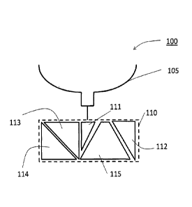
[0068] In an embodiment, as shown in FIG. 3, a floating platform 100 may
include, a
balloon 105, and in addition to the above mentioned components, a transponder
decoder,
logic circuits, release mechanisms and appropriate power supplies. These and
other
components may be housed in or on a payload box or an enclosure 110. Several
of the
payload components can be grouped together to form two or more separable
components
111, 112, 113, 114, and 115 while assuring proper weight and/or density
distribution for the
payload. The exact placement and connections between the units can be
determined by a'
person with skill in the art in order to assure proper weight and/or density
distribution for
the payload and antenna placement for the transponder.
[0069] The various components may be distributed such that each of the
components
has a weight and/or density less than a threshold. The threshold weight or
density may be
determined based on, for example, regulatory requirements of various agencies
or
jurisdictions, or other similar factors. In some embodiments, the payload may
be distributed
such that each of the components has a certain density profile. In some
embodiments, the
payload may be distributed such that each of the components has a volume or a
volume
' profile (i.e., area) no greater than a threshold. In some embodiments,
each of the
components may have a pre-defined limitation on its composition (e.g., each
component
17
CA 02972348 2017-06-27
WO 2016/105522
PCT/US2015/000278
may not have more than 10g of lead, or each component may not have more than
400g of
metal, etc.). In some embodiments, the payload may be distributed by function
such that a
particular component part performs a pre-defined function (e.g., a power-
supply
component, a transmission component, an altitude control component, etc.).
Alternatively,
in some embodiments, each of the components may be designed to be self-
sufficient (e.g.,
each component has its own power supply and transceiver) such that the payload
may
continue to at least partially function despite jettisoning of one of the
components. In some
embodiments each of the components may be designed to have a particular shape
(e.g.,
streamlined for descent, designed to increase drag, designed to have no hard
edges or
points to reduce damage on impact, etc.). One of skill in the art will
appreciate that this
configuration is merely an example, and not meant to be limiting. Other
configurations will
be readily apparent to one of skill in the art, and will depend on factors
such as, for
example, mission criticality of Various components, and weight and/or density
of various
components.
[0070] In various embodiments, release mechanisms 121, 122, 123, and 124,
depicted in
FIG. 3A, may function to release one or more components from the payload such
that the
released component(s) descend/s under gravity, in some cases, on a recovery
system (not
explicitly shown). Additionally, or alternatively, the release mechanism(s)
may function to
separate one or more components from the payload without releasing them such
that the
separated components release from the payload, but remain attached to the
platform via
one or more lines or other provisions. The employed release mechanism(s) may
be selected
from established or new methods of separating two or more objects from each
other.
Release mechanisms may include, for example:
(1) Various components may be spring loaded with pull apart electrical,
pneumatic,
or hydraulic connectors between the components as needed. A solenoid may be
configured
to act as a release mechanism allowing the springs to push the components away
from each
other. Each component may then be configured to descend under gravity on its
own
recovery system (e.g. parachute or maple-leaf recovery system);
(2) Various components may be held together with a cord that laces through
each
component. A cord cutter (e.g., thermal cutter, spring loaded blade, magnetic
release,
electrically releasable glue, chemically releasable glue, etc.) may be
configured to cut the
18
CA 02972348 2017-06-27
WO 2016/105522
PCT/US2015/000278
cord, allowing individual components to separate and come down under gravity
using a
controlled recovery system. The components may also be spring loaded in order
to
overcome friction of electrical or mechanical connectors between the
components;
(3) Various components may be held together with a cord that laces through
each
component. When the balloon is released from the payload components, the same
release
mechanism that releases the balloon may be configured to release the cord that
holds the
components together;
(4) Various components may be glued together (or to the payload, or platform).
The
glue may be electrically, or chemically releasable;
(5) Various components may be held together with a cord rolled on a motorized
drum. When the motor is activated, various components may be released together
or
sequentially;
(6) Multiple cords may be laced through a combination of components (e.g., one
cord from communications related components, one cord from weather sensing
related
components, one cord from altitude control mechanisms, etc.). Each of the
cords may have
a separate release mechanism similar to any one of the mechanisms described
herein;
(7) Entire payload or groups of components may be release while connected
together. The released payload may have an aerodynamic shape that causes
spinning as it
falls under gravity. While the payload is spinning, components are released
and centrifugal
forces fling components outward.
[0071) In
various embodiments, one or more components of the payload may be
released or separated at the same time, sequentially, or individually. In some
embodiments,
all of the components of the payload may be released at the same time. In such
embodiments, payload may be distributed into a large number of small, low-
weight, low-
density components. Since the released components will, typically, be
horizontally spaced
apart as they descend, such a release mechanism, however, carries a risk of
one another
aircraft hit multiple components as the fall as the aircraft movement is
essentially
horizontally. On the other hand, if an aircraft is at the same altitude or
immediately below
the platform, such a release mechanism may push the components sufficiently
apart to
completely avoid the aircraft.
19
CA 02972348 2017-06-27
WO 2016/105522 PCT/US2015/000278
[0072] In some embodiments, various components may be released or separated
sequentially. Such embodiments allow vertical spacing between components as
they fall
.under gravity. Such embodiments may also allow for controlled separation of
multiple
components on the same wire, whereby the separated components remain attached
to the
platform. Advantageously, since the components are on a single wire, tangling
of wire, and
components (and in case of release of components with recovery systems) may be
prevented. In an example embodiment, components are tied to each other with
separate
strings. Each of the strings is spooled on a single spool. Upon activation,
the spool releases
the components one at a time.
[0073] In some embodiments, various components may be released or separated
individually. For example, a payload may include multiple batteries, each of
which can be
separately released or separated as mission dictates. In addition, each
battery or battery
may be released after it's useful life is reached. In an example embodiment,
each
component has a separate string with its own release mechanism (e.g., a
thermal cutter). In
another example embodiment, each component is separately glued to the platform
using,
for example, an electrically releasable glue with individual circuits to
release the glue for
each Component. In either of the example embodiments, the separated components
may be
ultimately tied to the platform via one or more lines, whereby the components
remain
attached to the platform. Alternately, the separated components may be
released from the
platform, whereby the components (e.g., ballast weight) descend back to earth
under
gravity with the help of a recovery system.
[0074] Each of the separation and/or release sequences has its advantages
and
disadvantages, and the choice of a particular release/separation sequence may
depend on
factors such as, for example, distance of the platform from other aircraft(s),
probability of
released/separated components colliding with another aircraft, criticality of
components
with respect to functioning of the platform, need for continued functioning of
the platform
despite release/separation, complexity and cost of the particular release
mechanism,
geolocation of the platform at the time of release (e.g., if the platform is
over a restricted air
space, or critical infrastructure), weight and/or density distribution of the
components to be
released, and so forth. In some embodiment, there may be one or more redundant
release
=
CA 02972348 2017-06-27
WO 2016/105522 PCT/US2015/000278
mechanisms present on the floating platform. Redundancy may, in some instance,
be
mandated by a regulating agency.
[0075] In various embodiments, a component may remain connected to the
payload or
other components after separation via one or more lines. The one or more lines
may include
strings, wires, fiber optic cables, tubing, etc. Lines may carry power, data,
gases, rotary
motion, vibration, etc. to allow continued full or partial operation of the
component or
components connected to the line. In various embodiments, one or more of the
lines may
contain dereelers or rubber components to reduce the shock upon full extension
of the
line/s. In various embodiments, line length and strength may be set greater
than a
threshold, and/or to meet a regulator requirement.
[0076] In various embodiments, one or more connectors may connect lines to
components or to other lines. Such connectors may be adapted to transmit
fluids, pressure,
data, electrical power, light (e.g., connector for optic fiber cables), heat,
rotary motion, etc.
In some embodiments, connectors may slide apart, have a pre-set pull-apart
resistance,
have a spring contact, or may be magnetically coupled. Other connectors are
contemplated.
[0077] FIG. 4 depicts a flow diagram for method of breaking-up a floating
platform for
avoiding collision with an in-flight aircraft, according to an embodiment
disclosed herein.
The method includes: at block P401, determining if an in-flight aircraft is
within at least a
safety zone associated with a floating platform, wherein the floating platform
comprises
releasably-coupled component parts. In response to a determination that the in-
flight
aircraft is within at least the safety zone, at block P403 activating a
release mechanism. The
release mechanism is configured to uncouple the component parts..
[0078] The component parts may be distributed such that weight, density or
other
physical attributes of each of the component parts is less than a certain
value. Physical
attributes of the component parts may include, without limitation, weight of
the part,
density of the part, density profile of the part, composition of the part,
volume of the part,
volume profile of the part, shape of the part, and/or any combination thereof.
Density
profile indicates the distribution of density across the component part.
Examples of various
distribution
21
=
CA 02972348 2017-06-27
WO 2016/105522 PCT/US2015/000278
[0079] As used herein, the term "near-collision" refers to a situation
where a collision is
not imminent, but increased safety precautions that do not necessarily
terminate the
mission of the platform are required. FIG. 5A depicts a lateral view of the
space surrounding
the floating platform according to an embodiment of the present disclosure.
The space
surrounding floating platform 100 may be classified into three zones: (i)
collision zone 420;
(ii) safety zone 410; and (iii) safe zone (all space outside of safety zone
410). Zones may be
set based on physical distances (e.g., collision zone 420 extends 1 mile
laterally around and
1000 feet above and below the platform); time to closest aircraft approach
(e.g., collision
zone 420 extends a distance X in all directions around the platform where X is
calculated as
a distance travelled by an aircraft toward the platform in a given amount of
time, e.g., 2
minutes); aircraft closure rate; other variables, or a combination of
variables. In various
embodiments, zones may be changed based on the operating environment. Factors
such as,
time of the day (daytime versus night time), visual conditions (e.g., foggy,
cloudy, or
otherwise limited visibility conditions); airspace type (e.g., no-fly zones or
otherwise
restricted airspaces); population density at the geolocation of the platform,
etc.
[0080] Collision zone 420 may be defined as a space surrounding the
floating platform
defining a volume of unacceptably high risk of a collision (e.g., a
probability greater than
60%) between the floating platform (and/or components of the platform if they
were to be
released) and the aircraft. In an embodiment, as illustrated in FIG. 6A, an
aircraft in the
collision zone may cause a separation or release of all components 111, 112,
113, 114 and
115 carried by floating platform 100. As illustrated in Figure 5A, the
collision zone 420 may
exclude a volume of space 425 directly below the platform such that release of
components,
while an aircraft is directly below and close to the platform, is prevented.
The excluded
volume is more clearly illustrated in FIG. 5B which depicts a top view of the
space
surrounding floating platform 100.
[0081] Safety zone 410 may be defined as a volume of airspace surrounding
the collision
zone defining an area where collision is not imminent, but increased safety
precautions are
required. Typically, actions taken when an aircraft makes an incursion in the
safety zone
may allow full or partial continuation of the platform's mission. For example,
an aircraft in a
safety zone may cause separation of some or all components of the payload
without
releasing the components from the platform as illustrated in FIG. 63.
Alternatively, some of
22
CA 02972348 2017-06-27
WO 2016/105522 PCT/US2015/000278
the components (e.g., ballast weight, discharged batteries, etc.) may be
released. In various
embodiments, additional zones may be included for additional levels of safety.
As referred
to herein, a situation where an aircraft is in the safety zone may be referred
to as a near-
collision.
[0082] FIG. 7 depicts a flow diagram of a method for determining if a
collision between
the floating platform and an aircraft is imminent. At block P722, the location
(position) and
altitude of the floating platform is determined. At block P724, the position,
altitude and
heading of the aircraft are determined. At block P726, a probability of
collision between the
floating platform and the aircraft is calculated. The calculated probability,
in some
embodiments, is compared, at block P728, to a threshold to determine if a
collision is
imminent.
[0083] In some embodiments, the transponder decoder and/or other logic
circuits are
configured to monitor signals for an approaching aircraft, calculate the rate
of approach of
the aircraft and determine if the altitude of the aircraft will coincide with
the floating
platform. A probability of an imminent collision or a near collision is
calculated using these
signals.
[0084] In some embodiments, the aircraft position may be determined by one
or more
sensors on the floating platform. For example, the floating platform may
include a passive
collision avoidance system (PCAS) that receives data from aircraft
transponders. Other
examples may include, without limitation, optical detectors or cameras, laser
range finders,
LIDAR, acoustic sensors, thermal sensors, thermal cameras, RADAR, ADSB-in
(automatic
dependent surveillance broadcast receiver), and the like or any combination
thereof. In
some embodiments, the floating platform may receive information about
aircrafts from the
ground, e.g., via a ground-station or a ground-based controller. The
information from the
ground may include, for example, RADAR information, TCAS (Traffic Collision
Avoidance
System), flight control information (such as Flight Aware), flight plans, etc.
In some
embodiments, the floating platform may receive information about aircrafts
from other
floating platforms. For example, once one floating platform receives
information about an
aircraft using any of the aforementioned means, that floating platform may
broadcast the
information to other floating platforms in the area.
23
CA 02972348 2017-06-27
WO 2016/105522 PCT/US2015/000278
[0085] In an embodiment, if the probability of an imminent collision or a
near collision
exceeds a threshold, the release mechanism is activated such that the various
groups of
component parts are separated and released from the floating platform. For
example, if the
total payload weight is about 15 pounds, it can be divided in 3 parts ¨ one
with batteries,
weighing 6 pounds, one with the altitude control system (e.g., a ballast
system), weighing 5
pounds, and one with the antenna, electronics and rest of the payload,
weighing 4 pounds.
Other distributions are contemplated.
[0086] In an embodiment, the released components return to earth on
parachutes or a
similar recovery system. In another embodiment, some or all of the released
components
may be equipped with a homing beacon that broadcasts its position, e.g., using
GPS
coordinates so that the parts can be recovered.
[0087] In addition to the logic circuit monitoring the position and heading
of the aircraft,
in some embodiments, the position and heading of the floating platform may
also be
determined for improved accuracy. In an embodiment, flight path vector of the
floating
platform can be obtained using the rate of ascent or descent, float altitude,
float location,
and wind speeds and directions at the location of the floating platform. Based
on wind
speeds at various altitudes around that location, and based on the rate of
ascent of the
floating platform (which is dependent on the type and volume of gas within the
enclosure of
the floating platform), one can predict the location and altitude of the
floating platform at a
future time. The location and altitude of the floating platform as a function
of time can,
then, be expressed as a flight-path vector of the floating platform.
[0088] In some embodiments, only information relating to the current
position of the
aircraft may be available via the transponder decoder and/or other logic
circuits. In such
embodiments, determining the probability of collision or near-collision may be
based on a
current location method. Aircraft relative horizontal distance from platform
(ARHDP) is
determined by subtracting the platform position from the aircraft position.
Likewise, aircraft
relative altitude from platform (ARADP) is determined by subtracting the
platform altitude
from aircraft altitude. If the ARHDP and ARADP place the aircraft in the
collision zone or the
safety zone, the release mechanism may be activated.
24
CA 02972348 2017-06-27
WO 2016/105522 PCT/US2015/000278
[0089] In some embodiments, information relating to the aircraft flight
vector may be
available via the transponder decoder and/or other logic circuits. In such
embodiments,
several approaches may be used to determine the probability of collision or
near-collision.
In one method, the relative position of the aircraft relative to the platform
is determined
based on current positions of the aircraft and the platform. Additionally,
relative flight
vector of the aircraft relative to the platform is determined, e.g., by
subtracting platform
vector from aircraft vector. Based on the relative position and the relative
flight vector,
closest horizontal approach distance (CHAD), altitude difference at this
distance (AltD), and
time until closest approach (TCA) are determined. In another method,
sequential relative
distances and relative altitude are used to determine rate of closure between
the aircraft
and the platform, TCA, CHAD, and AltD. if CHAD and AltD place a probably
position of the
aircraft in the collision zone or the safety zone, the release mechanism is
activated.
[0090] As explained elsewhere herein, the actions performed by the release
mechanism
upon activation may be different based on whether the aircraft is in collision
zone or safety
zone. For example, components may be released from the platform such that the
components descend to earth under gravity if the aircraft is in the collision
zone. On the
other hand, if the aircraft is in the safety zone, the components may be
separated so as to
remain attached to the platform by,a line to provide distance between
components and still
allow functionality.
[0091] An embodiment disclosed herein relates to a rise rate control system
for the
floating platform. For example, a typical national weather service (NWS)
balloon system, as
is well known, may include of a rubber extensible balloon filled with a
lifting gas, a
parachute tied to the balloon, a line extending down from the parachute and a
radiosonde
tied to the end of that line. The radiosonde collects and transmits weather
related data
down to a ground station as the balloon system rises through the atmosphere.
[0092] The NWS requires that weather balloons rise at a standard rate of
about 1,000
feet per minute. This is nearly impossible to maintain throughout the
balloon's rise due to
many factors including the variance with altitude of the pressure and
temperature of both
the lifting gas and the ambient air, the variance in the balloon material, the
manufacturing
process, and the physical change in the size of the balloon itself as the
balloon rises.
CA 02972348 2017-06-27
WO 2016/105522
PCT/US2015/000278
[0093] In addition, a significant number of NWS weather balloons do not
obtain the
desired altitude of 100,000 feet because, among other reasons, the balloon
expands
significantly when obtaining the higher altitudes, becoming thin and many
times bursting
early for the reasons listed elsewhere herein. If the amount of gas could be
reduced at the
higher altitudes, the chance of balloon burst would be decreased.
[0094] Some embodiments described herein utilize a rise rate control system
to vent the
lifting gas as needed to slow the balloon's ascent to no more than 1,000 feet
per minute.
Additionally, by venting the lifting gas, the balloon size is reduced,
increasing the probability
of reaching the desired 100,000-foot altitude without bursting.
[0095] In an embodiment, the rise rate control system may include a venting
mechanism attached to the neck of the balloon that can release lifting gas
from the balloon,
a vent actuator for opening and closing the venting mechanism, an altitude
sensor for
determining the altitude and rise rate of the balloon system, and a comparing
mechanism or
circuit to control the vent actuator to cause the vent to release some lifting
gas when the
desired rise rate is greater than the desired value.
[0096] In one embodiment, a GPS unit provides the processor with rise rate
information.
The processor compares the current rise rate with the desired rise rate stored
in the
processor's memory. For the NWS balloon systems, the desired rise rate is
1,000 feet per
minute. If the current rise rate is higher than the desired rise rate, the
processor directs the
actuator to open the vent until the desired rise rate is achieved.
[0097] Additionally, a ballast system containing a ballast container,
ballast, and a ballast
actuator could be added to the rise rate control system. The processor
compares the
current rise rate with a minimum desired rise rate stored in the processor's
memory. If the
current rise rate is lower than the desired minimum rise rate, the processor,
may activate
the ballast actuator to drop ballast until the rise rate increases to the
desired value.
[0098] In an embodiment, a device for ensuring compliance with aviation
regulations
includes a payload having separable component parts; and a release mechanism
configured
to separate, upon activation, the component parts and release from the payload
such that a
weight, density, and/or other physical attributes of each of the component
parts is less than
26
CA 02972348 2017-06-27
WO 2016/105522 PCT/US2015/000278
a predetermined value, wherein the payload is carried by a floating platform.
The
predetermined value for the weight and/or density of each component part is
chosen to
assure compliance with aviation regulations.
[0099] In an embodiment, the release mechanism is activated when the
floating
platform, while descending, is at a given height from the ground so as to
prevent damage to
ground based persons or property. In some embodiments, the release mechanism
is
activated automatically after a certain height is reached during descent. In
other
embodiments, the activation of the release mechanism is dependent on the
terrain at the
ground location of the floating platform. The terrain information may be
stored on board
the floating platform, or may be obtained by one or more sensors (e.g., SONAR,
LIDAR, etc.)
available on the floating platform.
[00100] Another embodiment describes a system adapted to ensure compliance
with
aviation regulations. The system may, in various embodiments, include a
payload carried by
a floating platform, wherein the payload comprises a separable component
parts; a release
mechanism configured to separate, upon activation, the component parts and
release from
the payload such that a weight and/or density of each of the component parts
is less than a
predetermined value; and a controller configured to determine if a collision
or a near-
collision between the floating platform and an aircraft is imminent, wherein
the controller,
upon determination that a collision or a near-collision between the aircraft
and the floating
platform, activates the release mechanism.
[00101] In an embodiment, the controller receives input from a transponder
decoder
determining the position and heading of an aircraft. Another embodiment
includes a
positioning system that provides the location information related to the
floating platform. In
yet another embodiment, the controller is further configured to determine
position and
heading of the floating platform based on operating parameters of the floating
platform
such as, for example, the float position, float altitude, and wind velocities
at the float
position and altitude. In one or more aspects, the system may be configured to
determine
that an aircraft is within a set distance (e.g. 5 miles), and heading toward
the payload
(within 10 degrees).
27
CA 02972348 2017-06-27
WO 2016/105522 PCT/US2015/000278
[00102] In an embodiment, a probability of an imminent collision or near-
collision
between an aircraft and the floating platform is calculated. If the
probability is greater than
a predetermined threshold, the release mechanism is activated such that the
payload is
separated into component parts and released. The released component parts may
descend
back to earth using one of various recovery mechanisms, e.g., a parachute,
[00103] In addition to a situation when there is a threat of collision or
near-collision with
another aircraft, in some embodiments, the system may determine that it is
optimal to
terminate the flight of the floating platform or terminate (or pause)
transmission from the
floating platform completely. FIG. 8 schematically depicts the method of
making floating
platform flight termination decisions by a processor of the system.
[00104] In combination with an onboard power source 12 and GPS 14 (or other
geographic locator or tracking system), a processor 10 is provided to receive
position
information and rate of change of position (velocity) information 14. The
position
information is compared to stored or programmed criteria information at 16,
18, 20, 22, 24,
26, 28 and 30, to determine whether termination of radio transmission and/or
termination
of flight should be implemented.
[00105] In an embodiment, in the context of the floating platform being in a
US governed
airspace, the following criteria based decisions are provided with the
processor 10:
Has the platform moved or drifted outside of a certain geographic area? (See
FIG. 8, at 16.)
[00106] The relevant boundaries may be frequency license borders set by the
FCC as
dictated by a regional or nationwide broadcasting license. The FCC prohibits
transmitter
operation outside such geographic borders. Additionally, a neighboring country
may have
restrictions on transmitted power into their country from a foreign
transmitter. For
example, Mexico prohibits transmit power levels above ¨99 dBm on certain
frequencies into
Mexico from the United States. These restrictions are not hard for terrestrial
towers to
comply with as the towers can install and adjust directional antennas once
during
installation and not have to adjust them again thereafter. This is quite
different for a free
drifting high altitude ballooncraft containing a transmitter as the position
and altitude may
be constantly changing and may require the platform to stop transmitting while
still inside
28
CA 02972348 2017-06-27
WO 2016/105522 PCT/US2015/000278
the United States, but within a protective number of miles of the United
States-Mexico
border. Additionally, it may be desirable to take action if the floating
platform drifts inside
of or within a certain distance of a restricted or undesirable area such as an
area in which
recovery is difficult or an area in which aircraft are prohibited. Thus, it
may be desirable to
terminate flight and/or transmission if the platform moves into or outside
certain
geographic areas.
Is the platform moving outside of boundaries that would significantly reduce
the probability
of recovering the platform? (See FIG. 8 at 18.)
[00107] As payloads costs may be significant, from $50 to $150 for a typical
weather
service radiosonde, up to several hundreds of dollars for a transceiver
platform, and up to
many tens of thousands of dollars for a scientific payload, recovery may be
important both
financially and for environmental reasons. A platform may encounter strong
winds
especially in the jet stream as it descends from high altitudes. In order to
keep the platform
from drifting out of the country on descent, artificial borders that take into
account the
winds during descent can be used. Also, boundaries of large bodies of water
such as the
great lakes, seas and oceans the crossing of which might hamper or prevent
recovery of the
platform upon normal decent, may be taken into account for termination of
flight purposes.
Has the platform fallen below or risen above a set altitude range? (See FIG. 8
at 20)
[00108] Most scientific and weather balloons reach altitudes above 60,000
feet. The FAA
regulates airspace below 60,000 feet and discourages free floating craft or
uncontrolled
flight craft from loitering, especially in commercial air lanes, as they
present a hazard to
commercial planes. Current NWS weather balloons do not have the capability to
terminate
the flight if they start to hover below 60,000 feet. Even the large-scale
scientific balloons
may become errant and free drift below 60,000 feet.
Is the platform velocity sufficient to create an unacceptably large doppler
shift in the
transmission frequency? (See FIG. 8, at 22)
[00109] A ballooncraft traveling in the jet stream may reach speeds of over
180 miles per
hour. This creates a Doppler shift in the frequencies received on the ground.
The FCC
29
CA 02972348 2017-06-27
WO 2016/105522
PCT/US2015/000278
regulates the amount of total frequency drift allowed on transmissions.
Doppler shift
contributes to this total frequency drift and if great enough can cause the
transmitter to
transmit out of its allowed band. Therefore, it may be desirable that the
payload be able to
immediately stop transmitting past the speed at which the Doppler shift
becomes too great.
Does the platform fall rate indicate a balloon burst? (See FIG. 8, at 24.)
[00110] A fast fall rate indicates that the balloon has burst and that the
platform is falling.
Transmission from the platform may need to be terminated in such a situation.
Alternatively, a homing beacon transmission may be initiated.
Is the platform rising too slowly during ascent? (See FIG. 8, at 26.)
[00111] This indicates that the gas enclosure of the floating platform is
under-filled or
leaking. A slow rise rate may present a danger to aircraft by loitering
excessively at one
altitude particularly at an altitude in designated air lanes. Flight
termination may be optimal
in such situations.
Has the processor, the position finding equipment, or the primary power
failed? (See FIG. 8,
at 28.)
[00112] A GPS, star tracker, or system power failure should initiate an on-
board
termination. The platform must be able to terminate without processor control
or power to
prevent the platform from being lost without a trace and thereby, potentially
pose hazard to
commercial flights.
Have command and control communications been lost? (See FIG. 8, at 30.)
[00113] Without command and control from the ground, the payload should cease
transmission and the flight should be terminated.
[00114] The systems and devices disclosed herein detect the foregoing
conditions by
comparing current position, velocity, and operating conditions to stored,
programmed or
calculated criteria using an onboard processor or controller. The systems and
devices utilize
a GPS unit and a processor to determine the current platform's geographic
coordinates and
velocities. A GPS unit or pressure sensor determines the platform altitude.
The processor
CA 02972348 2017-06-27
WO 2016/105522
PCT/US2015/000278
algorithms will implement the complete set of conditions listed above causing
the ballast to
be released at 34, the transmitter to be shut off at 38 and the flight
terminated at 36 upon
detection of a stored, programmed or calculated termination criteria. Under
conditions of a
power loss or processor failure, the transmitter will also be shut off at 38,
and the flight will
be terminated at 36. The methods and mechanisms for the termination actions
are
described more fully below.
[00115] A separate termination controller 11, which may be under separate
power 13
monitors the primary platform power at 32 and monitors processor functions at
30 to
determine if the processor 10 is functioning properly. Both the primary
processor 10 and the
separate termination controller 11 have the ability to terminate
transmissions, by
discharging the primary platform batteries at 38 and to terminate the flight
by releasing the
balloon or activating the release mechanism disclosed herein at 36. The
separate power
source 13 may advantageously comprise a very small environmentally acceptable
battery
such as an alkaline watch battery.
[00116] FIG. 9 depicts a schematic of a floating platform in communication
with a ground
station and/or other floating platforms. Floating platform 900a may
communicate with
ground station 950 and/or other floating platforms 900b, 900c, etc. In some
embodiments,
release mechanism(s) associated with floating platforms 900a, 900b, 900c etc.
may be
activated remotely via ground station 950 or any one or more of the other
floating
platforms. For example, in a use case scenario, there is a failure of the
system for detecting
aircraft on a particular platform, e.g., 900a. In such a scenario, a ground
station 950, or one
of the other floating platforms may still be able to detect that an aircraft
is within a safety
zone or a collision zone associated with platform 900a. Ground station 950, or
one of the
other floating platforms, e.g., 900b may be able to activate release
mechanism(s) associated
with platform 900a via a communication link. Communication between platform
900a, and
ground station 950 may also include other data transmission.
[00117] Another embodiment is implemented as a program product for
implementing
systems and methods described herein. Some embodiments can take the form of an
entirely
hardware embodiment, an entirely software embodiment, or an embodiment
containing
31
CA 02972348 2017-06-27
WO 2016/105522 PCT/US2015/000278
both hardware and software elements. One embodiment is implemented in
software, which
includes but is not limited to firmware, resident software, microcode, etc.
[00118] Furthermore, embodiments can take the form of a computer program
product
(or machine-accessible product) accessible from a computer-usable or computer-
readable
medium providing program code for use by or in connection with a computer or
any
instruction execution system. For the purposes of this description, a computer-
usable or
computer readable medium can be any apparatus that can contain, store,
communicate,
propagate, or transport the program for use by or in connection with the
instruction
execution system, apparatus, or device.
[00119] The medium can be an electronic, magnetic, optical, electromagnetic,
infrared,
or semiconductor system (or apparatus or device). Examples of a computer-
readable
medium include a semiconductor or solid-state memory, magnetic tape, a
removable
computer diskette, a random access memory (RAM), a read-only memory (ROM), a
rigid
magnetic disk, and an optical disk. Current examples of optical disks include
compact disk ¨
read only memory (CD-ROM), compact disk ¨ read/write (CD-R/W), and DVD.
[00120] A data processing system suitable for storing and/or executing program
code will
include at least one processor coupled directly or indirectly to memory
elements through a
system bus. The memory elements can include local memory employed during
actual
execution of the program code, bulk storage, and cache memories which provide
temporary
storage of at least some program code in order to reduce the number of times
code must be
retrieved from bulk storage during execution.
[00121] The logic as described above may be part of the design for an
integrated circuit
chip. The chip design is created in a graphical computer programming language,
and stored
in a computer storage medium (such as a disk, tape, physical hard drive, or
virtual hard drive
such as in a storage access network). If the designer does not fabricate chips
or the
photolithographic masks used to fabricate chips, the designer transmits the
resulting design
by physical means (e.g., by providing a copy of the storage medium storing the
design) or
electronically (e.g., through the Internet) to such entities, directly or
indirectly. The stored
design is then converted into the appropriate format (e.g., GDSII) for the
fabrication.
32
CA 02972348 2017-06-27
WO 2016/105522
PCT/US2015/000278
[00122] The resulting integrated circuit chips can be distributed by the
fabricator in raw
wafer form (that is, as a single wafer that has multiple unpackaged chips), as
a bare die, or in
a packaged form. In the latter case, the chip is mounted in a single chip
package (such as a
plastic carrier, with leads that are affixed to a motherboard or other higher
level carrier) or
in a multichip package (such as a ceramic carrier that has either or both
surface
interconnections or buried interconnections). In any case, the chip is then
integrated with
other chips, discrete circuit elements, and/or other signal processing devices
as part of
either (a) an intermediate product, such as a motherboard, or (b) an end
product.
[00123] The foregoing detailed description has set forth various embodiments
of the
devices and/or processes by the use of diagrams, flowcharts, and/or examples.
Insofar as
such diagrams, flowcharts, and/or examples contain one or more functions
and/or
operations, it will be understood by those within the art that each function
and/or
operation within such diagrams, flowcharts, or examples can be implemented,
individually
and/or collectively, by a wide range of hardware, software, firmware, or
virtually any
combination thereof.
[00124] Those skilled in the art will recognize that it is common within
the art to describe
devices and/or processes in the fashion set forth herein, and thereafter use
engineering
practices to integrate such described devices and/or processes into data
processing
systems. That is, at least a portion of the devices and/or processes described
herein can be
integrated into a data processing system via a reasonable amount of
experimentation.
[00125] The herein described subject matter sometimes illustrates different
components
contained within, or connected with, different other components. It is to be
understood
that such depicted architectures are merely exemplary, and that in fact many
other
architectures can be implemented which achieve the same functionality. In a
conceptual
sense, any arrangement of components to achieve the same functionality is
effectively
"associated" such that the desired functionality is achieved. Hence, any two
components
herein combined to achieve a particular functionality can be seen as
"associated with" each
other such that the desired functionality is achieved, irrespective of
architectures or
intermediate components.
33
84024929
[00126] With respect to the use of substantially any plural and/or
singular terms herein,
those having skill in the art can translate from the plural to the singular
and/or from the singular
to the plural as is appropriate to the context and/or application. The various
singular/plural
permutations may be expressly set forth herein for sake of clarity.
[00127]
[00128] While various aspects and embodiments have been disclosed
herein, other
aspects and embodiments will be apparent to those skilled in the art. The
various aspects and
embodiments disclosed herein are for purposes of illustration and are not
intended to be limiting,
with the true scope and spirit being indicated by the following claims.
34
Date Recue/Date Received 2022-06-21