Note: Descriptions are shown in the official language in which they were submitted.
CA 02992429 2018-01-12
WO 2016/201033
PCT/US2016/036574
DATA MODEL FOR HOME AUTOMATION
Inventors:
Ken SUNDERMEYER
Corey GATES
Chris DECENZO
Paul J. DAWES
Aaron WOOD
Abhay GUPTA
RELATED APPLICATIONS
This application claims the benefit of United States (US) Patent Application
Number 62/172,885, filed June 9, 2015.
This application claims the benefit of US Patent Application Number
62/172,913,
filed June 9, 2015.
This application is a continuation in part application of US Patent
Application
Number 12/189,780, filed August 11,2008.
This application is a continuation in part application of US Patent
Application
Number 13/531,757, filed June 25, 2012.
This application is a continuation in part application of US Patent
Application
Number 12/197,958, filed August 25, 2008.
This application is a continuation in part application of US Patent
Application
Number 13/334,998, filed December 22, 2011.
This application is a continuation in part application of US Patent
Application
Number 12/539,537, filed August 11, 2009.
This application is a continuation in part application of US Patent
Application
Number 14/645,808, filed March 12, 2015.
1
CA 02992429 2018-01-12
WO 2016/201033 PCT/US2016/036574
This application is a continuation in part application of US Patent
Application
Number 13/104,932, filed May 10, 2011.
This application is a continuation in part application of US Patent
Application
Number 13/929,568, filed June 27, 2013.
This application is a continuation in part application of US Patent
Application
Number 14/628,651, filed February 23, 2015.
This application is a continuation in part application of US Patent
Application
Number 13/718,851, filed December 18, 2012.
This application is a continuation in part application of US Patent
Application
Number 12/972,740, filed December 20, 2010.
This application is a continuation in part application of US Patent
Application
Number 13/954,553, filed July 30, 2013.
This application is a continuation in part application of US Patent
Application
Number 14/943,162, filed November 17, 2015.
TECHNICAL FIELD
The embodiments described herein relate generally to a method and apparatus
for
improving the capabilities of security systems in home and business
applications. More
particularly, the embodiments described herein relate to a touchscreen device
that
integrates security system control and functionality with network content
interactivity,
management and presentation.
BACKGROUND
The field of home and small business security is dominated by technology
suppliers who build comprehensive 'closed' security systems, where the
individual
components (sensors, security panels, keypads) operate solely within the
confines of a
single vendor solution. For example, a wireless motion sensor from vendor A
cannot be
used with a security panel from vendor B. Each vendor typically has developed
sophisticated proprietary wireless technologies to enable the installation and
management
2
CA 02992429 2018-01-12
WO 2016/201033 PCT/US2016/036574
of wireless sensors, with little or no ability for the wireless devices to
operate separate
from the vendor's homogeneous system. Furthermore, these traditional systems
are
extremely limited in their ability to interface either to a local or wide area
standards-
based network (such as an IP network); most installed systems support only a
low-
bandwidth, intermittent connection utilizing phone lines or cellular (RF)
backup systems.
Wireless security technology from providers such as GE Security, Honeywell,
and
DSC/Tyco are well known in the art, and are examples of this proprietary
approach to
security systems for home and business.
Furthermore, with the proliferation of the internet, ethernet and WiFi local
area
networks (LANs) and advanced wide area networks (WANs) that offer high
bandwidth,
low latency connections (broadband), as well as more advanced wireless WAN
data
networks (e.g. GPRS or CDMA 1 xRTT) there increasingly exists the networking
capability to extend these traditional security systems to offer enhanced
functionality. In
addition, the proliferation of broadband access has driven a corresponding
increase in
home and small business networking technologies and devices. It is desirable
to extend
traditional security systems to encompass enhanced functionality such as the
ability to
control and manage security systems from the world wide web, cellular
telephones, or
advanced function internet-based devices. Other desired functionality includes
an open
systems approach to interface home security systems to home and small business
networks.
Due to the proprietary approach described above, the traditional vendors are
the
only ones capable of taking advantage of these new network functions. To date,
even
though the vast majority of home and business customers have broadband network
access
in their premises, most security systems do not offer the advanced
capabilities associated
with high speed, low-latency LANs and WANs. This is primarily because the
proprietary
vendors have not been able to deliver such technology efficiently or
effectively. Solution
providers attempting to address this need are becoming known in the art,
including three
categories of vendors: traditional proprietary hardware providers such as
Honeywell and
3
CA 02992429 2018-01-12
WO 2016/201033 PCT/US2016/036574
GE Security; third party hard-wired module providers such as Alarm.com,
NextAlarm,
and uControl; and new proprietary systems providers such as InGrid.
A disadvantage of the prior art technologies of the traditional proprietary
hardware providers arises due to the continued proprietary approach of these
vendors. As
they develop technology in this area it once again operates only with the
hardware from
that specific vendor, ignoring the need for a heterogeneous, cross-vendor
solution. Yet
another disadvantage of the prior art technologies of the traditional
proprietary hardware
providers arises due to the lack of experience and capability of these
companies in
creating open internet and web based solutions, and consumer friendly
interfaces.
A disadvantage of the prior art technologies of the third party hard-wired
module
providers arises due to the installation and operational complexities and
functional
limitations associated with hardwiring a new component into existing security
systems.
Moreover, a disadvantage of the prior art technologies of the new proprietary
systems
providers arises due to the need to discard all prior technologies, and
implement an
entirely new form of security system to access the new functionalities
associated with
broadband and wireless data networks. There remains, therefore, a need for
systems,
devices, and methods that easily interface to and control the existing
proprietary security
technologies utilizing a variety of wireless technologies.
=
INCORPORATION BY REFERENCE
Each patent, patent application, and/or publication mentioned in this
specification
is herein incorporated by reference in its entirety to the same extent as if
each individual
patent, patent application, and/or publication was specifically and
individually indicated
to be incorporated by reference.
BRIEF DESCRIPTION OF THE DRAWINGS
Figure 1 is a block diagram of the integrated security system, under an
embodiment.
4
CA 02992429 2018-01-12
WO 2016/201033 PCT/US2016/036574
Figure 2 is a block diagram of components of the integrated security system,
under an embodiment.
Figure 3 is a block diagram of the gateway software or applications, under an
embodiment.
Figure 4 is a block diagram of the gateway components, under an embodiment.
Figure 5 is a block diagram of IP device integration with a premise network,
under an embodiment.
Figure 6 is a block diagram of IP device integration with a premise network,
under an alternative embodiment.
Figure 7 is a block diagram of a touchscreen, under an embodiment.
Figure 8 is an example screenshot of a networked security touchscreen, under
an
embodiment.
Figure 9 is a block diagram of network or premise device integration with a
premise network, under an embodiment.
Figure 10 is a block diagram of network or premise device integration with a
premise network, under an alternative embodiment.
Figure 11 is a flow diagram for a method of forming a security network
including
integrated security system components, under an embodiment.
Figure 12 is a flow diagram for a method of forming a security network
including
integrated security system components and network devices, under an
embodiment.
Figure 13 is a flow diagram for installation of an IP device into a private
network
environment, under an embodiment.
Figure 14 is a block diagram showing communications among IP devices of the
private network environment, under an embodiment.
Figure 15 is a flow diagram of a method of integrating an external control and
management application system with an existing security system, under an
embodiment.
Figure 16 is a block diagram of an integrated security system wirelessly
interfacing to proprietary security systems, under an embodiment.
5
CA 02992429 2018-01-12
WO 2016/201033
PCT/US2016/036574
Figure 17 is a flow diagram for wirelessly 'learning' the gateway into an
existing
security system and discovering extant sensors, under an embodiment.
Figure 18 is a block diagram of a security system in which the legacy panel is
replaced with a wireless security panel wirelessly coupled to a gateway, under
an
embodiment.
Figure 19 is a block diagram of a security system in which the legacy panel is
replaced with a wireless security panel wirelessly coupled to a gateway, and a
touchscreen, under an alternative embodiment.
Figure 20 is a block diagram of a security system in which the legacy panel is
replaced with a wireless security panel connected to a gateway via an Ethernet
coupling,
under another alternative embodiment.
Figure 21 is a flow diagram for automatic takeover of a security system, under
an
embodiment.
Figure 22 is a flow diagram for automatic takeover of a security system, under
an
alternative embodiment.
Figure 23 is a general flow diagram for IP video control, under an embodiment.
Figure 24 is a block diagram showing camera tunneling, under an embodiment.
Figure 25 shows example request commands, under an embodiment.
Figure 26 shows different examples of selecting thermostat modes, under an
embodiment.
Figure 27 shows examples of toggle commands, under an embodiment.
Figure 28 shows range commands for lights and theimostats, under an
embodiment.
Figure 29 shows a text input command, under an embodiment.
Figure 30 is an example site object (e.g., "Cabin"), under an embodiment.
Figure 31 is an example summary object, under an embodiment.
Figure 32 shows example security objects, under an embodiment.
Figure 33 shows a remote client user interface, under an embodiment.
6
CA 02992429 2018-01-12
WO 2016/201033 PCT/US2016/036574
Figure 34 is an example of a shift object that is a main shift button, under
an
embodiment.
Figure 35 is a messaging object, under an embodiment.
Figure 36 is an example alarm message with "Disarm" button or icon, under an
embodiment.
Figure 37 is an example home view settings object, under an embodiment.
Figure 38 is an example home view and device data object showing the overlay
(left view), floor plan (middle view), and floor plan with device data overlay
(right view),
under an embodiment.
Figure 39 shows examples of different sensor group, under an embodiment.
Figure 40 is a table of elements for device state objects (e.g., Z-Wave and
camera
device state objects), under an embodiment.
Figure 41 shows various examples of door objects, under an embodiment.
Figure 42 shows various example lighting objects, under an embodiment.
Figure 43 shows various example thermostat objects, under an embodiment.
Figure 44 shows various example camera objects, under an embodiment.
Figure 45 is a flow diagram for playing live video, under an embodiment.
Figure 46 shows various example energyMeter objects, under an embodiment.
Figures 47A and 4713 (collectively "Figure 47") show an example login error
code table, under an embodiment.
Figure 48 shows example displays of text history by type, under an embodiment.
Figure 49 shows an example display of text history by device ID, under an
embodiment.
Figure 50 shows example displays of text history by user ID, under an
embodiment.
Figure 51 shows example displays of media history by camera ID, under an
embodiment.
Figure 52 shows an example display of graph history for a thermostat device,
under an embodiment.
7
CA 02992429 2018-01-12
WO 2016/201033 PCT/US2016/036574
Figure 53 shows an example display of graph history for an energy device,
under
an embodiment.
Figure 54 is a flow diagram for closed queries (discrete history request),
under an
embodiment.
Figure 55 is a flow diagram for open queries (continuous history updates),
under
an embodiment.
Figure 56 is a history processor service (class) description, under an
embodiment.
Figure 57 is a flow diagram for a cache process, under an embodiment.
DETAILED DESCRIPTION
An integrated security system is described that integrates broadband and
mobile
access and control with conventional security systems and premise devices to
provide a
tri-mode security network (broadband, cellular/GSM, POTS access) that enables
users to
remotely stay connected to their premises. The integrated security system,
while
delivering remote premise monitoring and control functionality to conventional
monitored premise protection, complements existing premise protection
equipment. The
integrated security system integrates into the premise network and couples
wirelessly
with the conventional security panel, enabling broadband access to premise
security
systems. Automation devices (cameras, lamp modules, thermostats, etc.) can be
added,
enabling users to remotely see live video and/or pictures and control home
devices via
their personal web portal or webpage, mobile phone, and/or other remote client
device.
Users can also receive notifications via email or text message when happenings
occur, or
do not occur, in their home.
Although the detailed description herein contains many specifics for the
purposes
of illustration, anyone of ordinary skill in the art will appreciate that many
variations and
alterations to the following details are within the scope of the embodiments
described
herein. Thus, the following illustrative embodiments are set forth without any
loss of
generality to, and without imposing limitations upon, the claimed invention.
8
CA 02992429 2018-01-12
WO 2016/201033 PCT/US2016/036574
As described herein, computer networks suitable for use with the embodiments
described herein include local area networks (LAN), wide area networks (WAN),
Internet, or other connection services and network variations such as the
world wide web,
the public intemet, a private intemet, a private computer network, a public
network, a
mobile network, a cellular network, a value-added network, and the like.
Computing
devices coupled or connected to the network may be any microprocessor
controlled
device that permits access to the network, including terminal devices, such as
personal
computers, workstations, servers, mini computers, main-frame computers, laptop
computers, mobile computers, palm top computers, hand held computers, mobile
phones,
TV set-top boxes, or combinations thereof. The computer network may include
one of
more LANs, WANs, Intemets, and computers. The computers may serve as servers,
clients, or a combination thereof.
The integrated security system can be a component of a single system, multiple
systems, and/or geographically separate systems. The integrated security
system can also
be a subcomponent or subsystem of a single system, multiple systems, and/or
geographically separate systems. The integrated security system can be coupled
to one or
more other components (not shown) of a host system or a system coupled to the
host
system.
One or more components of the integrated security system and/or a
corresponding
system or application to which the integrated security system is coupled or
connected
includes and/or runs under and/or in association with a processing system. The
processing system includes any collection of processor-based devices or
computing
devices operating together, or components of processing systems or devices, as
is known
in the art. For example, the processing system can include one or more of a
portable
computer, portable communication device operating in a communication network,
and/or
a network server. The portable computer can be any of a number and/or
combination of
devices selected from among personal computers, personal digital assistants,
portable
computing devices, and portable communication devices, but is not so limited.
The
processing system can include components within a larger computer system.
9
CA 02992429 2018-01-12
WO 2016/201033 PCT/US2016/036574
The processing system of an embodiment includes at least one processor and at
least one memory device or subsystem. The processing system can also include
or be
coupled to at least one database. The term "processor" as generally used
herein refers to
any logic processing unit, such as one or more central processing units
(CPUs), digital
signal processors (DSPs), application-specific integrated circuits (ASIC),
etc. The
processor and memory can be monolithically integrated onto a single chip,
distributed
among a number of chips or components, and/or provided by some combination of
algorithms. The methods described herein can be implemented in one or more of
software algorithm(s), programs, firmware, hardware, components, circuitry, in
any
combination.
The components of any system that includes the integrated security system can
be
located together or in separate locations. Communication paths couple the
components
and include any medium for communicating or transferring files among the
components.
The communication paths include wireless connections, wired connections, and
hybrid
wireless/wired connections. The communication paths also include couplings or
connections to networks including local area networks (LANs), metropolitan
area
networks (MANs), wide area networks (WANs), proprietary networks, interoffice
or
backend networks, and the Internet. Furthermore, the communication paths
include
removable fixed mediums like floppy disks, hard disk drives, and CD-ROM disks,
as
well as flash RAM, Universal Serial Bus (USB) connections, RS-232 connections,
telephone lines, buses, and electronic mail messages.
Aspects of the integrated security system and corresponding systems and
methods
described herein may be implemented as functionality programmed into any of a
variety
of circuitry, including programmable logic devices (PLDs), such as field
programmable
gate arrays (FPGAs), programmable array logic (PAL) devices, electrically
programmable logic and memory devices and standard cell-based devices, as well
as
application specific integrated circuits (ASICs). Some other possibilities for
implementing aspects of the integrated security system and corresponding
systems and
methods include: microcontrollers with memory (such as electronically erasable
CA 02992429 2018-01-12
WO 2016/201033 PCT/US2016/036574
programmable read only memory (EEPROM)), embedded microprocessors, firmware,
software, etc. Furthermore, aspects of the integrated security system and
corresponding
systems and methods may be embodied in microprocessors having software-based
circuit
emulation, discrete logic (sequential and combinatorial), custom devices,
fuzzy (neural)
logic, quantum devices, and hybrids of any of the above device types. Of
course the
underlying device technologies may be provided in a variety of component
types, e.g.,
metal-oxide semiconductor field-effect transistor (MOSFET) technologies like
complementary metal-oxide semiconductor (CMOS), bipolar technologies like
emitter-
coupled logic (ECL), polymer technologies (e.g., silicon-conjugated polymer
and metal-
conjugated polymer-metal structures), mixed analog and digital, etc.
It should be noted that any system, method, and/or other components disclosed
herein may be described using computer aided design tools and expressed (or
represented), as data and/or instructions embodied in various computer-
readable media,
in terms of their behavioral, register transfer, logic component, transistor,
layout
geometries, and/or other characteristics. Computer-readable media in which
such
formatted data and/or instructions may be embodied include, but are not
limited to, non-
volatile storage media in various forms (e.g., optical, magnetic or
semiconductor storage
media) and carrier waves that may be used to transfer such formatted data
and/or
instructions through wireless, optical, or wired signaling media or any
combination
thereof. Examples of transfers of such formatted data and/or instructions by
carrier
waves include, but are not limited to, transfers (uploads, downloads, e-mail,
etc.) over the
Internet and/or other computer networks via one or more data transfer
protocols (e.g.,
HTTP, FTP, SMTP, etc.). When received within a computer system via one or more
computer-readable media, such data and/or instruction-based expressions of the
above
described components may be processed by a processing entity (e.g., one or
more
processors) within the computer system in conjunction with execution of one or
more
other computer programs.
Unless the context clearly requires otherwise, throughout the description and
the
claims, the words "comprise," "comprising," and the like are to be construed
in an
11
CA 02992429 2018-01-12
WO 2016/201033 PCT/US2016/036574
inclusive sense as opposed to an exclusive or exhaustive sense; that is to
say, in a sense of
"including, but not limited to." Words using the singular or plural number
also include
the plural or singular number respectively. Additionally, the words "herein,"
"hereunder," "above," "below," and words of similar import, when used in this
application, refer to this application as a whole and not to any particular
portions of this
application. When the word "or" is used in reference to a list of two or more
items, that
word covers all of the following interpretations of the word: any of the items
in the list,
all of the items in the list and any combination of the items in the list.
The above description of embodiments of the integrated security system and
corresponding systems and methods is not intended to be exhaustive or to limit
the
systems and methods to the precise forms disclosed. While specific embodiments
of, and
examples for, the integrated security system and corresponding systems and
methods are
described herein for illustrative purposes, various equivalent modifications
are possible
within the scope of the systems and methods, as those skilled in the relevant
art will
recognize. The teachings of the integrated security system and corresponding
systems
and methods provided herein can be applied to other systems and methods, not
only for
the systems and methods described above.
The elements and acts of the various embodiments described above can be
combined to provide further embodiments. These and other changes can be made
to the
integrated security system and corresponding systems and methods in light of
the above
detailed description.
In accordance with the embodiments described herein, a wireless system (e.g.,
radio frequency (RF)) is provided that enables a security provider or consumer
to extend
the capabilities of an existing RF-capable security system or a non-RF-capable
security
system that has been upgraded to support RF capabilities. The system includes
an RF-
capable Gateway device (physically located within RF range of the RF-capable
security
system) and associated software operating on the Gateway device. The system
also
includes a web server, application server, and remote database providing a
persistent
store for information related to the system.
12
CA 02992429 2018-01-12
WO 2016/201033 PCT/US2016/036574
The security systems of an embodiment, referred to herein as the iControl
security
system or integrated security system, extend the value of traditional home
security by
adding broadband access and the advantages of remote home monitoring and home
control through the formation of a security network including components of
the
integrated security system integrated with a conventional premise security
system and a
premise local area network (LAN). With the integrated security system,
conventional
home security sensors, cameras, touchscreen keypads, lighting controls, and/or
Internet
Protocol (IP) devices in the home (or business) become connected devices that
are
accessible anywhere in the world from a web browser, mobile phone or through
content-
enabled touchscreens. The integrated security system experience allows
security
operators to both extend the value proposition of their monitored security
systems and
reach new consumers that include broadband users interested in staying
connected to
their family, home and property when they are away from home.
The integrated security system of an embodiment includes security servers
(also
referred to herein as iConnect servers or security network servers) and an
iHub gateway
(also referred to herein as the gateway, the iHub, or the iHub client) that
couples or
integrates into a home network (e.g., LAN) and communicates directly with the
home
security panel, in both wired and wireless installations. The security system
of an
embodiment automatically discovers the security system components (e.g.,
sensors, etc.)
belonging to the security system and connected to a control panel of the
security system
and provides consumers with full two-way access via web and mobile portals.
The
gateway supports various wireless protocols and can interconnect with a wide
range of
control panels offered by security system providers. Service providers and
users can then
extend the system's capabilities with the additional IP cameras, lighting
modules or
security devices such as interactive touchscreen keypads. The integrated
security system
adds an enhanced value to these security systems by enabling consumers to stay
connected through email and SMS alerts, photo push, event-based video capture
and rule-
based monitoring and notifications. This solution extends the reach of home
security to
households with broadband access.
13
CA 02992429 2018-01-12
WO 2016/201033 PCT/US2016/036574
The integrated security system builds upon the foundation afforded by
traditional
security systems by layering broadband and mobile access, IP cameras,
interactive
touchscreens, and an open approach to home automation on top of traditional
security
system configurations. The integrated security system is easily installed and
managed by
the security operator, and simplifies the traditional security installation
process, as
described below.
The integrated security system provides an open systems solution to the home
security market. As such, the foundation of the integrated security system
customer
premises equipment (CPE) approach has been to abstract devices, and allows
applications
to manipulate and manage multiple devices from any vendor. The integrated
security
system DeviceConnect technology that enables this capability supports
protocols,
devices, and panels from GE Security and Honeywell, as well as consumer
devices using
Z-Wave, IP cameras (e.g., Ethernet, wifi, and Homeplug), and IP touchscreens.
The
DeviceConnect is a device abstraction layer that enables any device or
protocol layer to
interoperate with integrated security system components. This architecture
enables the
addition of new devices supporting any of these interfaces, as well as add
entirely new
protocols.
The benefit of DeviceConnect is that it provides supplier flexibility. The
same
consistent touchscreen, web, and mobile user experience operate unchanged on
whatever
security equipment selected by a security system provider, with the system
provider's
choice of IP cameras, backend data center and central station software.
The integrated security system provides a complete system that integrates or
layers on top of a conventional host security system available from a security
system
provider. The security system provider therefore can select different
components or
configurations to offer (e.g., CDMA, GPRS, no cellular, etc.) as well as have
iControl
modify the integrated security system configuration for the system provider's
specific
needs (e.g., change the functionality of the web or mobile portal, add a GE or
Honeywell-
compatible TouchScreen, etc.).
14
CA 02992429 2018-01-12
WO 2016/201033
PCT/US2016/036574
The integrated security system integrates with the security system provider
infrastructure for central station reporting directly via Broadband and GPRS
alarm
transmissions. Traditional dial-up reporting is supported via the standard
panel
connectivity. Additionally, the integrated security system provides interfaces
for
advanced functionality to the CMS, including enhanced alarm events, system
installation
optimizations, system test verification, video verification, 2-way voice over
IP and GSM.
The integrated security system is an IP centric system that includes broadband
connectivity so that the gateway augments the existing security system with
broadband
and GPRS connectivity. If broadband is down or unavailable GPRS may be used,
for
example. The integrated security system supports GPRS connectivity using an
optional
wireless package that includes a GPRS modem in the gateway. The integrated
security
system treats the GPRS connection as a higher cost though flexible option for
data
transfers. In an embodiment the GPRS connection is only used to route alarm
events
(e.g., for cost), however the gateway can be configured (e.g., through the
iConnect server
interface) to act as a primary channel and pass any or all events over GPRS.
Consequently, the integrated security system does not interfere with the
current plain old
telephone service (POTS) security panel interface. Alarm events can still be
routed
through POTS; however the gateway also allows such events to be routed through
a
broadband or GPRS connection as well. The integrated security system provides
a web
application interface to the CSR tool suite as well as XML web services
interfaces for
programmatic integration between the security system provider's existing call
center
products. The integrated security system includes, for example, APIs that
allow the
security system provider to integrate components of the integrated security
system into a
custom call center interface. The APIs include XML web service APIs for
integration of
existing security system provider call center applications with the integrated
security
system service. All functionality available in the CSR Web application is
provided with
these API sets. The Java and XML-based APIs of the integrated security system
support
provisioning, billing, system administration, CSR, central station, portal
user interfaces,
and content management functions, to name a few. The integrated security
system can
CA 02992429 2018-01-12
WO 2016/201033
PCT/US2016/036574
provide a customized interface to the security system provider's billing
system, or
alternatively can provide security system developers with APIs and support in
the
integration effort.
The integrated security system provides or includes business component
interfaces for provisioning, administration, and customer care to name a few.
Standard
templates and examples are provided with a defined customer professional
services
engagement to help integrate OSS/BSS systems of a Service Provider with the
integrated
security system.
The integrated security system components support and allow for the
integration
of customer account creation and deletion with a security system. The iConnect
APIs
provides access to the provisioning and account management system in iConnect
and
provide full support for account creation, provisioning, and deletion.
Depending on the
requirements of the security system provider, the iConnect APIs can be used to
completely customize any aspect of the integrated security system backend
operational
system.
The integrated security system includes a gateway that supports the following
standards-based interfaces, to name a few: Ethernet IP communications via
Ethernet ports
on the gateway, and standard XML/TCP/IP protocols and ports are employed over
secured SSL sessions; USB 2.0 via ports on the gateway; 802.11b/g/n IP
communications; GSM/GPRS RF WAN communications; CDMA 1 xRTT RF WAN
communications (optional, can also support EVDO and 3G technologies).
The gateway supports the following proprietary interfaces, to name a few:
interfaces including Dialog RF network (319.5 MHz) and RS485 Superbus 2000
wired
interface; RF mesh network (908 MHz); and interfaces including RF network (345
MHz)
and RS485/RS232bus wired interfaces.
Regarding security for the IP communications (e.g., authentication,
authorization,
encryption, anti-spoofing, etc), the integrated security system uses SSL to
encrypt all IP
traffic, using server and client-certificates for authentication, as well as
authentication in
the data sent over the SSL-encrypted channel. For encryption, integrated
security system
16
CA 02992429 2018-01-12
WO 2016/201033 PCT/US2016/036574
issues public/private key pairs at the time/place of manufacture, and
certificates are not
stored in any online storage in an embodiment.
The integrated security system does not need any special rules at the customer
premise and/or at the security system provider central station because the
integrated
security system makes outgoing connections using TCP over the standard HTTP
and
HTTPS ports. Provided outbound TCP connections are allowed then no special
requirements on the firewalls are necessary.
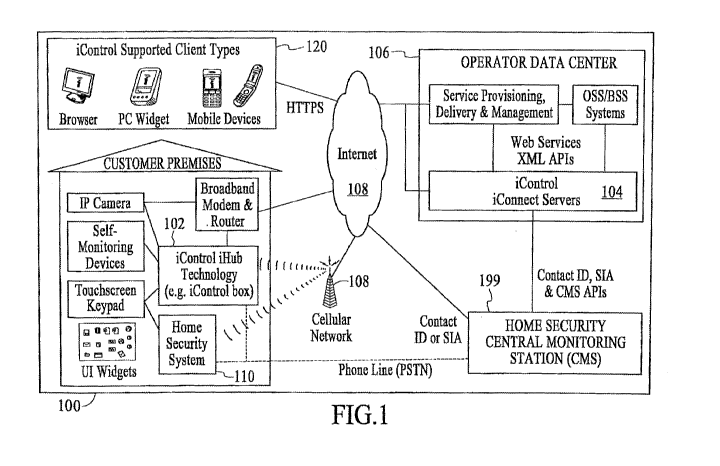
Figure 1 is a block diagram of the integrated security system 100, under an
embodiment. The integrated security system 100 of an embodiment includes the
gateway
102 and the security servers 104 coupled to the conventional home security
system 110.
At a customer's home or business, the gateway 102 connects and manages the
diverse
variety of home security and self-monitoring devices. The gateway 102
communicates
with the iConnect Servers 104 located in the service provider's data center
106 (or hosted
in integrated security system data center), with the communication taking
place via a
communication network 108 or other network (e.g., cellular network, intemet,
etc.).
These servers 104 manage the system integrations necessary to deliver the
integrated
system service described herein. The combination of the gateway 102 and the
iConnect
servers 104 enable a wide variety of remote client devices 120 (e.g., PCs,
mobile phones
and PDAs) allowing users to remotely stay in touch with their home, business
and family.
In addition, the technology allows home security and self-monitoring
information, as well
as relevant third party content such as traffic and weather, to be presented
in intuitive
ways within the home, such as on advanced touchscreen keypads.
The integrated security system service (also referred to as iControl service)
can be
managed by a service provider via browser-based Maintenance and Service
Management
applications that are provided with the iConnect Servers. Or, if desired, the
service can
be more tightly integrated with existing OSS/BSS and service delivery systems
via the
iConnect web services-based XML APIs.
The integrated security system service can also coordinate the sending of
alarms
to the home security Central Monitoring Station (CMS) 199. Alarms are passed
to the
17
CA 02992429 2018-01-12
WO 2016/201033 PCT/US2016/036574
CMS 199 using standard protocols such as Contact ID or SIA and can be
generated from
the home security panel location as well as by iConnect server 104 conditions
(such as
lack of communications with the integrated security system). In addition, the
link
between the security servers 104 and CMS 199 provides tighter integration
between
home security and self-monitoring devices and the gateway 102. Such
integration
enables advanced security capabilities such as the ability for CMS personnel
to view
photos taken at the time a burglary alarm was triggered. For maximum security,
the
gateway 102 and iConnect servers 104 support the use of a mobile network (both
GPRS
and CDMA options are available) as a backup to the primary broadband
connection.
The integrated security system service is delivered by hosted servers running
software components that communicate with a variety of client types while
interacting
with other systems. Figure 2 is a block diagram of components of the
integrated security
system 100, under an embodiment. Following is a more detailed description of
the
components.
The iConnect servers 104 support a diverse collection of clients 120 ranging
from
mobile devices, to PCs, to in-home security devices, to a service provider's
internal
systems. Most clients 120 are used by end-users, but there are also a number
of clients
120 that are used to operate the service.
Clients 120 used by end-users of the integrated security system 100 include,
but
are not limited to, the following:
Clients based on gateway client applications 202 (e.g., a processor-based
device running the gateway technology that manages home security and
automation devices).
A web browser 204 accessing a Web Portal application, performing end-
user configuration and customization of the integrated security system service
as
well as monitoring of in-home device status, viewing photos and video, etc.
Device and user management can also be performed by this portal application.
A mobile device 206 (e.g., PDA, mobile phone, etc.) accessing the
integrated security system Mobile Portal. This type of client 206 is used by
end-
18
CA 02992429 2018-01-12
WO 2016/201033
PCT/US2016/036574
users to view system status and perform operations on devices (e.g., turning
on a
lamp, arming a security panel, etc.) rather than for system configuration
tasks
such as adding a new device or user.
PC or browser-based "widget" containers 208 that present integrated
security system service content, as well as other third-party content, in
simple,
targeted ways (e.g. a widget that resides on a PC desktop and shows live video
from a single in-home camera). "Widget" as used herein means applications or
programs in the system.
Touchscreen home security keypads 208 and advanced in-home devices
that present a variety of content widgets via an intuitive touchscreen user
interface.
Notification recipients 210 (e.g., cell phones that receive SMS-based
notifications when certain events occur (or don't occur), email clients that
receive
an email message with similar information, etc.).
Custom-built clients (not shown) that access the iConnect web services
XML API to interact with users' home security and self-monitoring information
in new and unique ways. Such clients could include new types of mobile
devices,
or complex applications where integrated security system content is integrated
into a broader set of application features.
In addition to the end-user clients, the iConnect servers 104 support PC
browser-
based Service Management clients that manage the ongoing operation of the
overall
service. These clients run applications that handle tasks such as
provisioning, service
monitoring, customer support and reporting.
There are numerous types of server components of the iConnect servers 104 of
an
embodiment including, but not limited to, the following: Business Components
which
manage information about all of the home security and self-monitoring devices;
End-
User Application Components which display that information for users and
access the
Business Components via published XML APIs; and Service Management Application
Components which enable operators to administer the service (these components
also
19
CA 02992429 2018-01-12
WO 2016/201033
PCT/US2016/036574
access the Business Components via the XML APIs, and also via published SNMP
MIBs).
The server components provide access to, and management of, the objects
associated with an integrated security system installation. The top-level
object is the
"network." It is a location where a gateway 102 is located, and is also
commonly
referred to as a site or premises; the premises can include any type of
structure (e.g.,
home, office, warehouse, etc.) at which a gateway 102 is located. Users can
only access
the networks to which they have been granted permission. Within a network,
every
object monitored by the gateway 102 is called a device. Devices include the
sensors,
cameras, home security panels and automation devices, as well as the
controller or
processor-based device running the gateway applications.
Various types of interactions are possible between the objects in a system.
Automations define actions that occur as a result of a change in state of a
device. For
example, take a picture with the front entry camera when the front door sensor
changes to
"open". Notifications are messages sent to users to indicate that something
has occurred,
such as the front door going to "open" state, or has not occurred (referred to
as an iWatch
notification). Schedules define changes in device states that are to take
place at
predefined days and times. For example, set the security panel to "Armed" mode
every
weeknight at 11:00pm.
The iConnect Business Components are responsible for orchestrating all of the
low-level service management activities for the integrated security system
service. They
define all of the users and devices associated with a network (site), analyze
how the
devices interact, and trigger associated actions (such as sending
notifications to users).
All changes in device states are monitored and logged. The Business Components
also
manage all interactions with external systems as required, including sending
alarms and
other related self-monitoring data to the home security Central Monitoring
System
(CMS) 199. The Business Components are implemented as portable Java J2EE
Servlets,
but are not so limited.
CA 02992429 2018-01-12
WO 2016/201033
PCT/US2016/036574
The following iConnect Business Components manage the main elements of the
integrated security system service, but the embodiment is not so limited:
A Registry Manager 220 defines and manages users and networks. This
component is responsible for the creation, modification and termination of
users
and networks. It is also where a user's access to networks is defined.
A Network Manager 222 defines and manages security and self-
monitoring devices that are deployed on a network (site). This component
handles the creation, modification, deletion and configuration of the devices,
as
well as the creation of automations, schedules and notification rules
associated
with those devices.
A Data Manager 224 manages access to current and logged state data for
an existing network and its devices. This component specifically does not
provide any access to network management capabilities, such as adding new
devices to a network, which are handled exclusively by the Network Manager
222.
To achieve optimal performance for all types of queries, data for current
device states is stored separately from historical state data (a.k.a. "logs")
in the
database. A Log Data Manager 226 performs ongoing transfers of current device
state data to the historical data log tables.
Additional iConnect Business Components handle direct communications with
certain clients and other systems, for example:
An iHub Manager 228 directly manages all communications with gateway
clients, including receiving information about device state changes, changing
the
configuration of devices, and pushing new versions of the gateway client to
the
hardware it is running on.
A Notification Manager 230 is responsible for sending all notifications to
clients via SMS (mobile phone messages), email (via a relay server like an
SMTP
email server), etc.
21
CA 02992429 2018-01-12
WO 2016/201033
PCT/US2016/036574
An Alarm and CMS Manager 232 sends critical server-generated alarm
events to the home security Central Monitoring Station (CMS) and manages all
other communications of integrated security system service data to and from
the
CMS.
The Element Management System (EMS) 234 is an iControl Business
Component that manages all activities associated with service installation,
scaling
and monitoring, and filters and packages service operations data for use by
service management applications. The SNMP MIBs published by the EMS can
also be incorporated into any third party monitoring system if desired.
The iConnect Business Components store information about the objects that they
manage in the iControl Service Database 240 and in the iControl Content Store
242. The
iControl Content Store is used to store media objects like video, photos and
widget
content, while the Service Database stores information about users, networks,
and
devices. Database interaction is performed via a JDBC interface. For security
purposes,
the Business Components manage all data storage and retrieval.
The iControl Business Components provide web services-based APIs that
application components use to access the Business Components' capabilities.
Functions
of application components include presenting integrated security system
service data to
end-users, performing administrative duties, and integrating with external
systems and
back-office applications.
The primary published APIs for the iConnect Business Components include, but
are not limited to, the following:
A Registry Manager API 252 provides access to the Registry Manager
Business Component's functionality, allowing management of networks and
users.
A Network Manager API 254 provides access to the Network Manager
Business Component's functionality, allowing management of devices on a
network.
22
CA 02992429 2018-01-12
WO 2016/201033 PCT/US2016/036574
A Data Manager API 256 provides access to the Data Manager Business
Component's functionality, such as setting and retrieving (current and
historical)
data about device states.
A Provisioning API 258 provides a simple way to create new networks
and configure initial default properties.
Each API of an embodiment includes two modes of access: Java API or XML
API. The XML APIs are published as web services so that they can be easily
accessed by
applications or servers over a network. The Java APIs are a programmer-
friendly
wrapper for the XML APIs. Application components and integrations written in
Java
should generally use the Java APIs rather than the XML APIs directly.
The iConnect Business Components also have an XML-based interface 260 for
quickly adding support for new devices to the integrated security system. This
interface
260, referred to as DeviceConnect 260, is a flexible, standards-based
mechanism for
defining the properties of new devices and how they can be managed. Although
the
format is flexible enough to allow the addition of any type of future device,
pre-defined
XML profiles are currently available for adding common types of devices such
as sensors
(SensorConnect), home security panels (PanelConnect) and IP cameras
(CameraConnect).
The iConnect End-User Application Components deliver the user interfaces that
run on the different types of clients supported by the integrated security
system service.
The components are written in portable Java J2EE technology (e.g., as Java
Servlets, as
JavaServer Pages (JSPs), etc.) and they all interact with the iControl
Business
Components via the published APIs.
The following End-User Application Components generate CSS-based
HTML/JavaScript that is displayed on the target client. These applications can
be
dynamically branded with partner-specific logos and URL links (such as
Customer
Support, etc.). The End-User Application Components of an embodiment include,
but
are not limited to, the following:
23
CA 02992429 2018-01-12
WO 2016/201033 PCT/US2016/036574
An iControl Activation Application 270 that delivers the first application
that a user sees when they set up the integrated security system service. This
wizard-based web browser application securely associates a new user with a
purchased gateway and the other devices included with it as a kit (if any). It
primarily uses functionality published by the Provisioning API.
An iControl Web Portal Application 272 runs on PC browsers and delivers
the web-based interface to the integrated security system service. This
application
allows users to manage their networks (e.g. add devices and create
automations)
as well as to view/change device states, and manage pictures and videos.
Because
of the wide scope of capabilities of this application, it uses three different
Business Component APIs that include the Registry Manager API, Network
Manager API, and Data Manager API, but the embodiment is not so limited.
An iControl Mobile Portal 274 is a small-footprint web-based interface
that runs on mobile phones and PDAs. This interface is optimized for remote
viewing of device states and pictures/videos rather than network management.
As
such, its interaction with the Business Components is primarily via the Data
Manager API.
Custom portals and targeted client applications can be provided that
leverage the same Business Component APIs used by the above applications.
A Content Manager Application Component 276 delivers content to a
variety of clients. It sends multimedia-rich user interface components to
widget
container clients (both PC and browser-based), as well as to advanced
touchscreen
keypad clients. In addition to providing content directly to end-user devices,
the
Content Manager 276 provides widget-based user interface components to satisfy
requests from other Application Components such as the iControl Web 272 and
Mobile 274 portals.
A number of Application Components are responsible for overall management of
the service. These pre-defined applications, referred to as Service Management
24
CA 02992429 2018-01-12
WO 2016/201033 PCT/US2016/036574
Application Components, are configured to offer off-the-shelf solutions for
production
management of the integrated security system service including provisioning,
overall
service monitoring, customer support, and reporting, for example. The Service
Management Application Components of an embodiment include, but are not
limited to,
the following:
A Service Management Application 280 allows service administrators to
perform activities associated with service installation, scaling and
monitoring/alerting. This application interacts heavily with the Element
Management System (EMS) Business Component to execute its functionality, and
also retrieves its monitoring data from that component via protocols such as
SNMP MIBs.
A Kitting Application 282 is used by employees performing service
provisioning tasks. This application allows home security and self-monitoring
devices to be associated with gateways during the warehouse kitting process.
A CSR Application and Report Generator 284 is used by personnel
supporting the integrated security system service, such as CSRs resolving end-
user issues and employees enquiring about overall service usage. The push of
new gateway firmware to deployed gateways is also managed by this application.
The iConnect servers 104 also support custom-built integrations with a service
provider's existing OSS/BSS, CSR and service delivery systems 290. Such
systems can
access the iConnect web services XML API to transfer data to and from the
iConnect
servers 104. These types of integrations can compliment or replace the PC
browser-
based Service Management applications, depending on service provider needs.
As described above, the integrated security system of an embodiment includes a
gateway, or iHub. The gateway of an embodiment includes a device that is
deployed in
the home or business and couples or connects the various third-party cameras,
home
security panels, sensors and devices to the iConnect server over a WAN
connection as
described in detail herein. The gateway couples to the home network and
communicates
directly with the home security panel in both wired and wireless sensor
installations. The
CA 02992429 2018-01-12
WO 2016/201033
PCT/US2016/036574
gateway is configured to be low-cost, reliable and thin so that it complements
the
integrated security system network-based architecture.
The gateway supports various wireless protocols and can interconnect with a
wide
range of home security control panels. Service providers and users can then
extend the
system's capabilities by adding IP cameras, lighting modules and additional
security
devices. The gateway is configurable to be integrated into many consumer
appliances,
including set-top boxes, routers and security panels. The small and efficient
footprint of
the gateway enables this portability and versatility, thereby simplifying and
reducing the
overall cost of the deployment.
Figure 3 is a block diagram of the gateway 102 including gateway software or
applications, under an embodiment. The gateway software architecture is
relatively thin
and efficient, thereby simplifying its integration into other consumer
appliances such as
set-top boxes, routers, touch screens and security panels. The software
architecture also
provides a high degree of security against unauthorized access. This section
describes the
various key components of the gateway software architecture.
The gateway application layer 302 is the main program that orchestrates the
operations performed by the gateway. The Security Engine 304 provides robust
protection against intentional and unintentional intrusion into the integrated
security
system network from the outside world (both from inside the premises as well
as from the
WAN). The Security Engine 304 of an embodiment comprises one or more sub-
modules
or components that perform functions including, but not limited to, the
following:
Encryption including 128-bit SSL encryption for gateway and iConnect
server communication to protect user data privacy and provide secure
communication.
Bi-directional authentication between the gateway and iConnect server in
order to prevent unauthorized spoofing and attacks. Data sent from the
iConnect
server to the gateway application (or vice versa) is digitally signed as an
additional layer of security. Digital signing provides both authentication and
validation that the data has not been altered in transit.
26
CA 02992429 2018-01-12
WO 2016/201033
PCT/US2016/036574
Camera SSL encapsulation because picture and video traffic offered by
off-the-shelf networked IP cameras is not secure when traveling over the
Internet.
The gateway provides for 128-bit SSL encapsulation of the user picture and
video
data sent over the intemet for complete user security and privacy.
802.11b/g/n with WPA-2 security to ensure that wireless camera
communications always takes place using the strongest available protection.
A gateway-enabled device is assigned a unique activation key for
activation with an iConnect server. This ensures that only valid gateway-
enabled
devices can be activated for use with the specific instance of iConnect server
in
use. Attempts to activate gateway-enabled devices by brute force are detected
by
the Security Engine. Partners deploying gateway-enabled devices have the
knowledge that only a gateway with the correct serial number and activation
key
can be activated for use with an iConnect server. Stolen devices, devices
attempting to masquerade as gateway-enabled devices, and malicious outsiders
(or insiders as knowledgeable but nefarious customers) cannot effect other
customers' gateway-enabled devices.
As standards evolve, and new encryption and authentication methods are proven
to be useful, and older mechanisms proven to be breakable, the security
manager can be
upgraded "over the air" to provide new and better security for communications
between
the iConnect server and the gateway application, and locally at the premises
to remove
any risk of eavesdropping on camera communications.
A Remote Firmware Download module 306 allows for seamless and secure
updates to the gateway firmware through the iControl Maintenance Application
on the
server 104, providing a transparent, hassle-free mechanism for the service
provider to
deploy new features and bug fixes to the installed user base. The firmware
download
mechanism is tolerant of connection loss, power interruption and user
interventions (both
intentional and unintentional). Such robustness reduces down time and customer
support
issues. Gateway firmware can be remotely download either for one gateway at a
time, a
group of gateways, or in batches.
27
CA 02992429 2018-01-12
WO 2016/201033
PCT/US2016/036574
The Automations engine 308 manages the user-defined rules of interaction
between the different devices (e.g. when door opens turn on the light). Though
the
automation rules are programmed and reside at the portal/server level, they
are cached at
the gateway level in order to provide short latency between device triggers
and actions.
DeviceConnect 310 includes definitions of all supported devices (e.g.,
cameras,
security panels, sensors, etc.) using a standardized plug-in architecture. The
DeviceConnect module 310 offers an interface that can be used to quickly add
support for
any new device as well as enabling interoperability between devices that use
different
technologies/protocols. For common device types, pre-defined sub-modules have
been
defined, making supporting new devices of these types even easier.
SensorConnect 312
is provided for adding new sensors, CameraConnect 316 for adding IP cameras,
and
PanelConnect 314 for adding home security panels.
The Schedules engine 318 is responsible for executing the user defined
schedules
(e.g., take a picture every five minutes; every day at 8am set temperature to
65 degrees
Fahrenheit, etc.). Though the schedules are programmed and reside at the
iConnect
server level they are sent to the scheduler within the gateway application.
The Schedules
Engine 318 then interfaces with SensorConnect 312 to ensure that scheduled
events occur
at precisely the desired time.
The Device Management module 320 is in charge of all discovery, installation
and configuration of both wired and wireless IP devices (e.g., cameras, etc.)
coupled or
connected to the system. Networked IP devices, such as those used in the
integrated
security system, require user configuration of many IP and security parameters
¨ to
simplify the user experience and reduce the customer support burden, the
device
management module of an embodiment handles the details of this configuration.
The
device management module also manages the video routing module described
below.
The video routing engine 322 is responsible for delivering seamless video
streams
to the user with zero-configuration. Through a multi-step, staged approach the
video
routing engine uses a combination of UPnP port-forwarding, relay server
routing and
STUN/TURN peer-to-peer routing.
28
CA 02992429 2018-01-12
WO 2016/201033 PCT/US2016/036574
Figure 4 is a block diagram of components of the gateway 102, under an
embodiment. Depending on the specific set of functionality desired by the
service
provider deploying the integrated security system service, the gateway 102 can
use any of
a number of processors 402, due to the small footprint of the gateway
application
firmware. In an embodiment, the gateway could include the Broadcom BCM5354 as
the
processor for example. In addition, the gateway 102 includes memory (e.g.,
FLASH 404,
RAM 406, etc.) and any number of input/output (I/O) ports 408.
Referring to the WAN portion 410 of the gateway102 , the gateway 102 of an
embodiment can communicate with the iConnect server using a number of
communication types and/or protocols, for example Broadband 412, GPRS 414
and/or
Public Switched Telephone Network (PTSN) 416 to name a few. In general,
broadband
communication 412 is the primary means of connection between the gateway 102
and the
iConnect server 104 and the GPRS/CDMA 414 and/or PSTN 416 interfaces acts as
back-
up for fault tolerance in case the user's broadband connection fails for
whatever reason,
but the embodiment is not so limited.
Referring to the LAN portion 420 of the gateway 102, various protocols and
physical transceivers can be used to communicate to off-the-shelf sensors and
cameras.
The gateway 102 is protocol-agnostic and technology-agnostic and as such can
easily
support almost any device networking protocol. The gateway 102 can, for
example,
support GE and Honeywell security RF protocols 422, Z-Wave 424, serial (RS232
and
RS485) 426 for direct connection to security panels as well as WiFi 428
(802.11b/g) for
communication to WiFi cameras.
The integrated security system includes couplings or connections among a
variety
of IP devices or components, and the device management module is in charge of
the
discovery, installation and configuration of the IP devices coupled or
connected to the
system, as described above. The integrated security system of an embodiment
uses a
"sandbox" network to discover and manage all IP devices coupled or connected
as
components of the system. The IP devices of an embodiment include wired
devices,
wireless devices, cameras, interactive touchscreens, and security panels to
name a few.
29
CA 02992429 2018-01-12
WO 2016/201033 PCT/US2016/036574
These devices can be wired via ethernet cable or Wifi devices, all of which
are secured
within the sandbox network, as described below. The "sandbox" network is
described in
detail below.
Figure 5 is a block diagram 500 of network or premise device integration with
a
premise network 250, under an embodiment. In an embodiment, network devices
255-
257 are coupled to the gateway 102 using a secure network coupling or
connection such
as SSL over an encrypted 802.11 link (utilizing for example WPA-2 security for
the
wireless encryption). The network coupling or connection between the gateway
102 and
the network devices 255-257 is a private coupling or connection in that it is
segregated
from any other network couplings or connections. The gateway 102 is coupled to
the
premise router/firewall 252 via a coupling with a premise LAN 250. The premise
router/firewall 252 is coupled to a broadband modem 251, and the broadband
modem 251
is coupled to a WAN 200 or other network outside the premise. The gateway 102
thus
enables or forms a separate wireless network, or sub-network, that includes
some number
of devices and is coupled or connected to the LAN 250 of the host premises.
The
gateway sub-network can include, but is not limited to, any number of other
devices like
WiFi IP cameras, security panels (e.g., IP-enabled), and security
touchscreens, to name a
few. The gateway 102 manages or controls the sub-network separately from the
LAN
250 and transfers data and information between components of the sub-network
and the
LAN 250/WAN 200, but is not so limited. Additionally, other network devices
254 can
be coupled to the LAN 250 without being coupled to the gateway 102.
Figure 6 is a block diagram 600 of network or premise device integration with
a
premise network 250, under an alternative embodiment. The network or premise
devices
255-257 are coupled to the gateway 102. The network coupling or connection
between
the gateway 102 and the network devices 255-257 is a private coupling or
connection in
that it is segregated from any other network couplings or connections. The
gateway 102
is coupled or connected between the premise router/firewall 252 and the
broadband
modem 251. The broadband modem 251 is coupled to a WAN 200 or other network
outside the premise, while the premise router/firewall 252 is coupled to a
premise LAN
CA 02992429 2018-01-12
WO 2016/201033 PCT/US2016/036574
250. As a result of its location between the broadband modem 251 and the
premise
router/firewall 252, the gateway 102 can be configured or function as the
premise router
routing specified data between the outside network (e.g., WAN 200) and the
premise
router/firewall 252 of the LAN 250. As described above, the gateway 102 in
this
configuration enables or forms a separate wireless network, or sub-network,
that includes
the network or premise devices 255-257 and is coupled or connected between the
LAN
250 of the host premises and the WAN 200. The gateway sub-network can include,
but is
not limited to, any number of network or premise devices 255-257 like WiFi IP
cameras,
security panels (e.g., IP-enabled), and security touchscreens, to name a few.
The gateway
102 manages or controls the sub-network separately from the LAN 250 and
transfers data
and information between components of the sub-network and the LAN 250/WAN 200,
but is not so limited. Additionally, other network devices 254 can be coupled
to the LAN
250 without being coupled to the gateway 102.
The examples described above with reference to Figures 5 and 6 are presented
only as examples of IP device integration. The integrated security system is
not limited
to the type, number and/or combination of IP devices shown and described in
these
examples, and any type, number and/or combination of IP devices is
contemplated within
the scope of this disclosure as capable of being integrated with the premise
network.
The integrated security system of an embodiment includes a touchscreen (also
referred to as the iControl touchscreen or integrated security system
touchscreen), as
described above, which provides core security keypad functionality, content
management
and presentation, and embedded systems design. The networked security
touchscreen
system of an embodiment enables a consumer or security provider to easily and
automatically install, configure and manage the security system and
touchscreen located
at a customer premise. Using this system the customer may access and control
the local
security system, local IP devices such as cameras, local sensors and control
devices (such
as lighting controls or pipe freeze sensors), as well as the local security
system panel and
associated security sensors (such as door/window, motion, and smoke
detectors). The
31
CA 02992429 2018-01-12
WO 2016/201033
PCT/US2016/036574
customer premise may be a home, business, and/or other location equipped with
a wired
or wireless broadband IP connection.
The system of an embodiment includes a touchscreen with a configurable
software user interface and/or a gateway device (e.g., iHub) that couples or
connects to a
premise security panel through a wired or wireless connection, and a remote
server that
provides access to content and information from the premises devices to a user
when they
are remote from the home. The touchscreen supports broadband and/or WAN
wireless
connectivity. In this embodiment, the touchscreen incorporates an IP broadband
connection (e.g., Wifi radio, Ethernet port, etc.), and/or a cellular radio
(e.g.,
GPRS/GSM, CDMA, WiMax, etc.). The touchscreen described herein can be used as
one or more of a security system interface panel and a network user interface
(UI) that
provides an interface to interact with a network (e.g., LAN, WAN, internet,
etc.).
The touchscreen of an embodiment provides an integrated touchscreen and
security panel as an all-in-one device. Once integrated using the touchscreen,
the
touchscreen and a security panel of a premise security system become
physically co-
located in one device, and the functionality of both may even be co-resident
on the same
CPU and memory (though this is not required).
The touchscreen of an embodiment also provides an integrated IP video and
touchscreen UI. As such, the touchscreen supports one or more standard video
CODECs/players (e.g., H.264, Flash Video, MOV, MPEG4, M-JPEG, etc.). The
touchscreen UI then provides a mechanism (such as a camera or video widget) to
play
video. In an embodiment the video is streamed live from an IP video camera. In
other
embodiments the video comprises video clips or photos sent from an IP camera
or from a
remote location.
The touchscreen of an embodiment provides a configurable user interface system
that includes a configuration supporting use as a security touchscreen. In
this
embodiment, the touchscreen utilizes a modular user interface that allows
components to
be modified easily by a service provider, an installer, or even the end user.
Examples of
such a modular approach include using Flash widgets, HTML-based widgets, or
other
32
CA 02992429 2018-01-12
WO 2016/201033
PCT/US2016/036574
downloadable code modules such that the user interface of the touchscreen can
be
updated and modified while the application is running. In an embodiment the
touchscreen user interface modules can be downloaded over the internet. For
example, a
new security configuration widget can be downloaded from a standard web
server, and
the touchscreen then loads such configuration app into memory, and inserts it
in place of
the old security configuration widget. The touchscreen of an embodiment is
configured
to provide a self-install user interface.
Embodiments of the networked security touchscreen system described herein
include a touchscreen device with a user interface that includes a security
toolbar
providing one or more functions including arm, disarm, panic, medic, and
alert. The
touchscreen therefore includes at least one screen having a separate region of
the screen
dedicated to a security toolbar. The security toolbar of an embodiment is
present in the
dedicated region at all times that the screen is active.
The touchscreen of an embodiment includes a home screen having a separate
region of the screen allocated to managing home-based functions. The home-
based
functions of an embodiment include managing, viewing, and/or controlling IP
video
cameras. In this embodiment, regions of the home screen are allocated in the
form of
widget icons; these widget icons (e.g. for cameras, thermostats, lighting,
etc) provide
functionality for managing home systems. So, for example, a displayed camera
icon,
when selected, launches a Camera Widget, and the Camera widget in turn
provides
access to video from one or more cameras, as well as providing the user with
relevant
camera controls (take a picture, focus the camera, etc.)
The touchscreen of an embodiment includes a home screen having a separate
region of the screen allocated to managing, viewing, and/or controlling
internet-based
content or applications. For example, the Widget Manager UI presents a region
of the
home screen (up to and including the entire home screen) where intern& widgets
icons
such as weather, sports, etc. may be accessed). Each of these icons may be
selected to
launch their respective content services.
33
CA 02992429 2018-01-12
WO 2016/201033
PCT/US2016/036574
The touchscreen of an embodiment is integrated into a premise network using
the
gateway, as described above. The gateway as described herein functions to
enable a
separate wireless network, or sub-network, that is coupled, connected, or
integrated with
another network (e.g., WAN, LAN of the host premises, etc.). The sub-network
enabled
by the gateway optimizes the installation process for IP devices, like the
touchscreen, that
couple or connect to the sub-network by segregating these IP devices from
other such
devices on the network. This segregation of the IP devices of the sub-network
further
enables separate security and privacy policies to be implemented for these IP
devices so
that, where the IP devices are dedicated to specific functions (e.g.,
security), the security
and privacy policies can be tailored specifically for the specific functions.
Furthermore,
the gateway and the sub-network it forms enables the segregation of data
traffic, resulting
in faster and more efficient data flow between components of the host network,
components of the sub-network, and between components of the sub-network and
components of the network.
The touchscreen of an embodiment includes a core functional embedded system
that includes an embedded operating system, required hardware drivers, and an
open
system interface to name a few. The core functional embedded system can be
provided
by or as a component of a conventional security system (e.g., security system
available
from GE Security). These core functional units are used with components of the
integrated security system as described herein. Note that portions of the
touchscreen
description below may include reference to a host premise security system
(e.g., GE
security system), but these references are included only as an example and do
not limit
the touchscreen to integration with any particular security system.
As an example, regarding the core functional embedded system, a reduced
memory footprint version of embedded Linux forms the core operating system in
an
embodiment, and provides basic TCP/IP stack and memory management functions,
along
with a basic set of low-level graphics primitives. A set of device drivers is
also provided
or included that offer low-level hardware and network interfaces. In addition
to the
standard drivers, an interface to the RS 485 bus is included that couples or
connects to the
34
CA 02992429 2018-01-12
WO 2016/201033
PCT/US2016/036574
security system panel (e.g., GE Concord panel). The interface may, for
example,
implement the Superbus 2000 protocol, which can then be utilized by the more
comprehensive transaction-level security functions implemented in PanelConnect
technology (e.g SetAlarmLevel (int level, int partition, char *accessCode)).
Power
control drivers are also provided.
Figure 7 is a block diagram of a touchscreen 700 of the integrated security
system, under an embodiment. The touchscreen 700 generally includes an
application/presentation layer 702 with a resident application 704, and a core
engine 706.
The touchscreen 700 also includes one or more of the following, but is not so
limited:
applications of premium services 710, widgets 712, a caching proxy 714,
network
security 716, network interface 718, security object 720, applications
supporting devices
722, PanelConnect API 724, a gateway interface 726, and one or more ports 728.
More specifically, the touchscreen, when configured as a home security device,
includes but is not limited to the following application or software modules:
RS 485
and/or RS-232 bus security protocols to conventional home security system
panel (e.g.,
GE Concord panel); functional home security classes and interfaces (e.g. Panel
ARM
state, Sensor status, etc.); Application/Presentation layer or engine;
Resident Application;
Consumer Home Security Application; installer home security application; core
engine;
and System bootloader/Software Updater. The core Application engine and system
bootloader can also be used to support other advanced content and
applications. This
provides a seamless interaction between the premise security application and
other
optional services such as weather widgets or IP cameras.
An alternative configuration of the touchscreen includes a first Application
engine
for premise security and a second Application engine for all other
applications. The
integrated security system application engine supports content standards such
as HTML,
XML, Flash, etc. and enables a rich consumer experience for all 'widgets',
whether
security-based or not. The touchscreen thus provides service providers the
ability to use
web content creation and management tools to build and download any 'widgets'
regardless of their functionality.
CA 02992429 2018-01-12
WO 2016/201033
PCT/US2016/036574
As discussed above, although the Security Applications have specific low-level
functional requirements in order to interface with the premise security
system, these
applications make use of the same fundamental application facilities as any
other
'widget', application facilities that include graphical layout, interactivity,
application
handoff, screen management, and network interfaces, to name a few.
Content management in the touchscreen provides the ability to leverage
conventional web development tools, performance optimized for an embedded
system,
service provider control of accessible content, content reliability in a
consumer device,
and consistency between 'widgets' and seamless widget operational environment.
In an
embodiment of the integrated security system, widgets are created by web
developers and
hosted on the integrated security system Content Manager (and stored in the
Content
Store database). In this embodiment the server component caches the widgets
and offers
them to consumers through the web-based integrated security system
provisioning
system. The servers interact with the advanced touchscreen using HTTPS
interfaces
controlled by the core engine and dynamically download widgets and updates as
needed
to be cached on the touchscreen. In other embodiments widgets can be accessed
directly
over a network such as the Internet without needing to go through the iControl
Content
Manager
Referring to Figure 7, the touchscreen system is built on a tiered
architecture,
with defined interfaces between the Application/Presentation Layer (the
Application
Engine) on the top, the Core Engine in the middle, and the security panel and
gateway
APIs at the lower level. The architecture is configured to provide maximum
flexibility
and ease of maintenance.
The application engine of the touchscreen provides the presentation and
interactivity capabilities for all applications (widgets) that run on the
touchscreen,
including both core security function widgets and third party content widgets.
Figure 8
is an example screenshot 800 of a networked security touchscreen, under an
embodiment.
This example screenshot 800 includes three interfaces or user interface (UI)
components
802-806, but is not so limited. A first UI 802 of the touchscreen includes
icons by which
36
CA 02992429 2018-01-12
WO 2016/201033 PCT/US2016/036574
a user controls or accesses functions and/or components of the security system
(e.g.,
"Main", "Panic", "Medic", "Fire", state of the premise alarm system (e.g.,
disarmed,
armed, etc.), etc.); the first UI 802, which is also referred to herein as a
security interface,
is always presented on the touchscreen. A second UI 804 of the touchscreen
includes
icons by which a user selects or interacts with services and other network
content (e.g.,
clock, calendar, weather, stocks, news, sports, photos, maps, music, etc.)
that is
accessible via the touchscreen. The second UI 804 is also referred to herein
as a network
interface or content interface. A third UI 806 of the touchscreen includes
icons by which
a user selects or interacts with additional services or componets (e.g.,
intercom control,
security, cameras coupled to the system in particular regions (e.g., front
door, baby, etc.)
available via the touchscreen.
A component of the application engine is the Presentation Engine, which
includes
a set of libraries that implement the standards-based widget content (e.g.,
XML, HTML,
JavaScript, Flash) layout and interactivity. This engine provides the widget
with
interfaces to dynamically load both graphics and application logic from third
parties,
support high level data description language as well as standard graphic
formats. The set
of web content-based functionality available to a widget developer is extended
by
specific touchscreen functions implemented as local web services by the Core
Engine.
The resident application of the touchscreen is the master service that
controls the
interaction of all widgets in the system, and enforces the business and
security rules
required by the service provider. For example, the resident application
determines the
priority of widgets, thereby enabling a home security widget to override
resource requests
from a less critical widget (e.g. a weather widget). The resident application
also
monitors widget behavior, and responds to client or server requests for cache
updates.
The core engine of the touchscreen manages interaction with other components
of
the integrated security system, and provides an interface through which the
resident
application and authorized widgets can get information about the home security
system,
set alarms, install sensors, etc. At the lower level, the Core Engine's main
interactions
are through the PanelConnect API, which handles all communication with the
security
37
CA 02992429 2018-01-12
WO 2016/201033
PCT/US2016/036574
panel, and the gateway Interface, which handles communication with the
gateway. In an
embodiment, both the iHub Interface and PanelConnect API are resident and
operating
on the touchscreen. In another embodiment, the PanelConnect API runs on the
gateway
or other device that provides security system interaction and is accessed by
the
touchscreen through a web services interface.
The Core Engine also handles application and service level persistent and
cached
memory functions, as well as the dynamic provisioning of content and widgets,
including
but not limited to: flash memory management, local widget and content caching,
widget
version management (download, cache flush new/old content versions), as well
as the
caching and synchronization of user preferences. As a portion of these
services the Core
engine incorporates the bootloader functionality that is responsible for
maintaining a
consistent software image on the touchscreen, and acts as the client agent for
all software
updates. The bootloader is configured to ensure full update redundancy so that
unsuccessful downloads cannot corrupt the integrated security system.
Video management is provided as a set of web services by the Core Engine.
Video management includes the retrieval and playback of local video feeds as
well as
remote control and management of cameras (all through iControl CameraConnect
technology).
Both the high level application layer and the mid-level core engine of the
touchscreen can make calls to the network. Any call to the network made by the
application layer is automatically handed off to a local caching proxy, which
determines
whether the request should be handled locally. Many of the requests from the
application
layer are web services API requests, although such requests could be satisfied
by the
iControl servers, they are handled directly by the touchscreen and the
gateway. Requests
that get through the caching proxy are checked against a white list of
acceptable sites,
and, if they match, are sent off through the network interface to the gateway.
Included in
the Network Subsystem is a set of network services including HTTP, HTTPS, and
server-
level authentication functions to manage the secure client-server interface.
Storage and
management of certificates is incorporated as a part of the network services
layer.
38
CA 02992429 2018-01-12
WO 2016/201033
PCT/US2016/036574
Server components of the integrated security system servers support
interactive
content services on the touchscreen. These server components include, but are
not
limited to the content manager, registry manager, network manager, and global
registry,
each of which is described herein.
The Content Manager oversees aspects of handling widget data and raw content
on the touchscreen. Once created and validated by the service provider,
widgets are
'ingested' to the Content Manager, and then become available as downloadable
services
through the integrated security system Content Management APIs. The Content
manager
maintains versions and timestamp information, and connects to the raw data
contained in
the backend Content Store database. When a widget is updated (or new content
becomes
available) all clients registering interest in a widget are systematically
updated as needed
(a process that can be configured at an account, locale, or system-wide
level).
The Registry Manager handles user data, and provisioning accounts, including
information about widgets the user has decided to install, and the user
preferences for
these widgets.
The Network Manager handles getting and setting state for all devices on the
integrated security system network (e.g., sensors, panels, cameras, etc.). The
Network
manager synchronizes with the gateway, the advanced touchscreen, and the
subscriber
database.
The Global Registry is a primary starting point server for all client
services, and is
a logical referral service that abstracts specific server locations/addresses
from clients
(touchscreen, gateway 102, desktop widgets, etc.). This approach enables easy
scaling/migration of server farms.
The touchscreen of an embodiment operates wirelessly with a premise security
system. The touchscreen of an embodiment incorporates an RF transceiver
component
that either communicates directly with the sensors and/or security panel over
the panel's
proprietary RF frequency, or the touchscreen communicates wirelessly to the
gateway
over 802.11, Ethernet, or other IP-based communications channel, as described
in detail
herein. In the latter case the gateway implements the PanelConnect interface
and
39
CA 02992429 2018-01-12
WO 2016/201033 PCT/US2016/036574
communicates directly to the security panel and/or sensors over wireless or
wired
networks as described in detail above.
The touchscreen of an embodiment is configured to operate with multiple
security
systems through the use of an abstracted security system interface. In this
embodiment,
the PanelConnect API can be configured to support a plurality of proprietary
security
system interfaces, either simultaneously or individually as described herein.
In one
embodiment of this approach, the touchscreen incorporates multiple physical
interfaces to
security panels (e.g. GE Security RS-485, Honeywell RF, etc.) in addition to
the
PanelConnect API implemented to support multiple security interfaces. The
change
needed to support this in PanelConnect is a configuration parameter specifying
the panel
type connection that is being utilized.
So for example, the setARMState() function is called with an additional
parameter
(e.g., Armstate = setARMState(type="ARM STAYI ARM AWAY] DISARM",
Parameters="ExitDelay=301Lights=OFF", panelType --"GE Concord4 RS485")). The
`panelType parameter is used by the setARMState function (and in practice by
all of the
PanelConnect functions) to select an algorithm appropriate to the specific
panel out of a
plurality of alogorithms.
The touchscreen of an embodiment is self-installable. Consequently, the
touchscreen provides a 'wizard' approach similar to that used in traditional
computer
installations (e.g. InstallShield). The wizard can be resident on the
touchscreen,
accessible through a web interface, or both. In one embodiment of a
touchscreen self-
installation process, the service provider can associate devices (sensors,
touchscreens,
security panels, lighting controls, etc.) remotely using a web-based
administrator
interface.
The touchscreen of an embodiment includes a battery backup system for a
security touchscreen. The touchscreen incorporates a standard Li-ion or other
battery and
charging circuitry to allow continued operation in the event of a power
outage. In an
embodiment the battery is physically located and connected within the
touchscreen
enclosure. In another embodiment the battery is located as a part of the power
CA 02992429 2018-01-12
WO 2016/201033 PCT/US2016/036574
transformer, or in between the power transformer and the touchscreen.
The example configurations of the integrated security system described above
with reference to Figures 5 and 6 include a gateway that is a separate device,
and the
touchscreen couples to the gateway. However, in an alternative embodiment, the
gateway device and its functionality can be incorporated into the touchscreen
so that the
device management module, which is now a component of or included in the
touchscreen, is in charge of the discovery, installation and configuration of
the IP devices
coupled or connected to the system, as described above. The integrated
security system
with the integrated touchscreen/gateway uses the same "sandbox" network to
discover
and manage all IP devices coupled or connected as components of the system.
The touchscreen of this alternative embodiment integrates the components of
the
gateway with the components of the touchscreen as described herein. More
specifically,
the touchscreen of this alternative embodiment includes software or
applications
described above with reference to Figure 3. In this alternative embodiment,
the
touchscreen includes the gateway application layer 302 as the main program
that
orchestrates the operations performed by the gateway. A Security Engine 304 of
the
touchscreen provides robust protection against intentional and unintentional
intrusion into
the integrated security system network from the outside world (both from
inside the
premises as well as from the WAN). The Security Engine 304 of an embodiment
comprises one or more sub-modules or components that perform functions
including, but
not limited to, the following:
Encryption including 128-bit SSL encryption for gateway and iConnect
server communication to protect user data privacy and provide secure
communication.
Bi-directional authentication between the touchscreen and iConnect server
in order to prevent unauthorized spoofing and attacks. Data sent from the
iConnect server to the gateway application (or vice versa) is digitally signed
as an
additional layer of security. Digital signing provides both authentication and
validation that the data has not been altered in transit.
41
CA 02992429 2018-01-12
WO 2016/201033 PCT/US2016/036574
Camera SSL encapsulation because picture and video traffic offered by
off-the-shelf networked IP cameras is not secure when traveling over the
Internet.
The touchscreen provides for 128-bit SSL encapsulation of the user picture and
video data sent over the intemet for complete user security and privacy.
802.11b/g/n with WPA-2 security to ensure that wireless camera
communications always takes place using the strongest available protection.
A touchscreen-enabled device is assigned a unique activation key for
activation with an iConnect server. This ensures that only valid gateway-
enabled
devices can be activated for use with the specific instance of iConnect server
in
use. Attempts to activate gateway-enabled devices by brute force are detected
by
the Security Engine. Partners deploying touchscreen-enabled devices have the
knowledge that only a gateway with the correct serial number and activation
key
can be activated for use with an iConnect server. Stolen devices, devices
attempting to masquerade as gateway-enabled devices, and malicious outsiders
(or insiders as knowledgeable but nefarious customers) cannot effect other
customers' gateway-enabled devices.
As standards evolve, and new encryption and authentication methods are proven
to be useful, and older mechanisms proven to be breakable, the security
manager can be
upgraded "over the air" to provide new and better security for communications
between
the iConnect server and the gateway application, and locally at the premises
to remove
any risk of eavesdropping on camera communications.
A Remote Firmware Download module 306 of the touchscreen allows for
seamless and secure updates to the gateway firmware through the iControl
Maintenance
Application on the server 104, providing a transparent, hassle-free mechanism
for the
service provider to deploy new features and bug fixes to the installed user
base. The
firmware download mechanism is tolerant of connection loss, power interruption
and user
interventions (both intentional and unintentional). Such robustness reduces
down time
and customer support issues. Touchscreen firmware can be remotely download
either for
one touchscreen at a time, a group of touchscreen, or in batches.
42
CA 02992429 2018-01-12
WO 2016/201033 PCT/US2016/036574
The Automations engine 308 of the touchscreen manages the user-defined rules
of
interaction between the different devices (e.g. when door opens turn on the
light).
Though the automation rules are programmed and reside at the portal/server
level, they
are cached at the gateway level in order to provide short latency between
device triggers
and actions.
DeviceConnect 310 of the touchscreen touchscreen includes definitions of all
supported devices (e.g., cameras, security panels, sensors, etc.) using a
standardized plug-
in architecture. The DeviceConnect module 310 offers an interface that can be
used to
quickly add support for any new device as well as enabling interoperability
between
devices that use different technologies/protocols. For common device types,
pre-defined
sub-modules have been defined, making supporting new devices of these types
even
easier. SensorConnect 312 is provided for adding new sensors, CameraConnect
316 for
adding IP cameras, and PanelConnect 314 for adding home security panels.
The Schedules engine 318 of the touchscreen is responsible for executing the
user
defined schedules (e.g., take a picture every five minutes; every day at 8am
set
temperature to 65 degrees Fahrenheit, etc.). Though the schedules are
programmed and
reside at the iConnect server level they are sent to the scheduler within the
gateway
application of the touchscreen. The Schedules Engine 318 then interfaces with
SensorConnect 312 to ensure that scheduled events occur at precisely the
desired time.
The Device Management module 320 of the touchscreen is in charge of all
discovery, installation and configuration of both wired and wireless IP
devices (e.g.,
cameras, etc.) coupled or connected to the system. Networked IP devices, such
as those
used in the integrated security system, require user configuration of many IP
and security
parameters, and the device management module of an embodiment handles the
details of
this configuration. The device management module also manages the video
routing
module described below.
The video routing engine 322 of the touchscreen is responsible for delivering
seamless video streams to the user with zero-configuration. Through a multi-
step, staged
approach the video routing engine uses a combination of UPnP port-forwarding,
relay
43
CA 02992429 2018-01-12
WO 2016/201033 PCT/US2016/036574
server routing and STUN/TURN peer-to-peer routing. The video routing engine is
described in detail in the Related Applications.
Figure 9 is a block diagram 900 of network or premise device integration with
a
premise network 250, under an embodiment. In an embodiment, network devices
255,
256, 957 are coupled to the touchscreen 902 using a secure network connection
such as
SSL over an encrypted 802.11 link (utilizing for example WPA-2 security for
the
wireless encryption), and the touchscreen 902 coupled to the premise
router/firewall 252
via a coupling with a premise LAN 250. The premise router/firewall 252 is
coupled to a
broadband modem 251, and the broadband modem 251 is coupled to a WAN 200 or
other
network outside the premise. The touchscreen 902 thus enables or forms a
separate
wireless network, or sub-network, that includes some number of devices and is
coupled
or connected to the LAN 250 of the host premises. The touchscreen sub-network
can
include, but is not limited to, any number of other devices like WiFi IP
cameras, security
panels (e.g., IP-enabled), and IP devices, to name a few. The touchscreen 902
manages
or controls the sub-network separately from the LAN 250 and transfers data and
information between components of the sub-network and the LAN 250/WAN 200, but
is
not so limited. Additionally, other network devices 254 can be coupled to the
LAN 250
without being coupled to the touchscreen 902.
Figure 10 is a block diagram 1000 of network or premise device integration
with
a premise network 250, under an alternative embodiment. The network or premise
devices 255, 256, 1057 are coupled to the touchscreen 1002, and the
touchscreen 1002 is
coupled or connected between the premise router/firewall 252 and the broadband
modem
251. The broadband modem 251 is coupled to a WAN 200 or other network outside
the
premise, while the premise router/firewall 252 is coupled to a premise LAN
250. As a
result of its location between the broadband modem 251 and the premise
router/firewall
252, the touchscreen 1002 can be configured or function as the premise router
routing
specified data between the outside network (e.g., WAN 200) and the premise
router/firewall 252 of the LAN 250. As described above, the touchscreen 1002
in this
configuration enables or forms a separate wireless network, or sub-network,
that includes
44
CA 02992429 2018-01-12
WO 2016/201033
PCT/US2016/036574
the network or premise devices 255, 156, 1057 and is coupled or connected
between the
LAN 250 of the host premises and the WAN 200. The touchscreen sub-network can
include, but is not limited to, any number of network or premise devices 255,
256, 1057
like WiFi IP cameras, security panels (e.g., IP-enabled), and security
touchscreens, to
name a few. The touchscreen 1002 manages or controls the sub-network
separately from
the LAN 250 and transfers data and information between components of the sub-
network
and the LAN 250/WAN 200, but is not so limited. Additionally, other network
devices
254 can be coupled to the LAN 250 without being coupled to the touchscreen
1002.
The gateway of an embodiment, whether a stand-along component or integrated
with a touchscreen, enables couplings or connections and thus the flow or
integration of
information between various components of the host premises and various types
and/or
combinations of IP devices, where the components of the host premises include
a
network (e.g., LAN) and/or a security system or subsystem to name a few.
Consequently, the gateway controls the association between and the flow of
information
or data between the components of the host premises. For example, the gateway
of an
embodiment forms a sub-network coupled to another network (e.g., WAN, LAN,
etc.),
with the sub-network including IP devices. The gateway further enables the
association
of the IP devices of the sub-network with appropriate systems on the premises
(e.g.,
security system, etc.). Therefore, for example, the gateway can form a sub-
network of IP
devices configured for security functions, and associate the sub-network only
with the
premises security system, thereby segregating the IP devices dedicated to
security from
other IP devices that may be coupled to another network on the premises.
The gateway of an embodiment, as described herein, enables couplings or
connections and thus the flow of information between various components of the
host
premises and various types and/or combinations of IP devices, where the
components of
the host premises include a network, a security system or subsystem to name a
few.
Consequently, the gateway controls the association between and the flow of
information
or data between the components of the host premises. For example, the gateway
of an
embodiment forms a sub-network coupled to another network (e.g., WAN, LAN,
etc.),
CA 02992429 2018-01-12
WO 2016/201033
PCT/US2016/036574
with the sub-network including IP devices. The gateway further enables the
association
of the IP devices of the sub-network with appropriate systems on the premises
(e.g.,
security system, etc.). Therefore, for example, the gateway can form a sub-
network of IP
devices configured for security functions, and associate the sub-network only
with the
premises security system, thereby segregating the IP devices dedicated to
security from
other IP devices that may be coupled to another network on the premises.
Figure 11 is a flow diagram for a method 1100 of folining a security network
including integrated security system components, under an embodiment.
Generally, the
method comprises coupling 1102 a gateway comprising a connection management
component to a local area network in a first location and a security server in
a second
location. The method comprises forming 1104 a security network by
automatically
establishing a wireless coupling between the gateway and a security system
using the
connection management component. The security system of an embodiment
comprises
security system components located at the first location. The method comprises
integrating 1106 communications and functions of the security system
components into
the security network via the wireless coupling.
Figure 12 is a flow diagram for a method 1200 of forming a security network
including integrated security system components and network devices, under an
embodiment. Generally, the method comprises coupling 1202 a gateway to a local
area
network located in a first location and a security server in a second
location. The method
comprises automatically establishing 1204 communications between the gateway
and
security system components at the first location, the security system
including the
security system components. The method comprises automatically establishing
1206
communications between the gateway and premise devices at the first location.
The
method comprises forming 1208 a security network by electronically
integrating, via the
gateway, communications and functions of the premise devices and the security
system
components.
In an example embodiment, Figure 13 is a flow diagram 1300 for integration or
installation of an IP device into a private network environment, under an
embodiment.
46
CA 02992429 2018-01-12
WO 2016/201033
PCT/US2016/036574
The IP device includes any IP-capable device that, for example, includes the
touchscreen
of an embodiment. The variables of an embodiment set at time of installation
include,
but are not limited to, one or more of a private SSID/Password, a gateway
identifier, a
security panel identifier, a user account TS, and a Central Monitoring Station
account
identification.
An embodiment of the IP device discovery and management begins with a user or
installer activating 1302 the gateway and initiating 1304 the install mode of
the system.
This places the gateway in an install mode. Once in install mode, the gateway
shifts to a
default (Install) Wifi configuration. This setting will match the default
setting for other
integrated security system-enabled devices that have been pre-configured to
work with
the integrated security system. The gateway will then begin to provide 1306
DHCP
addresses for these IP devices. Once the devices have acquired a new DHCP
address
from the gateway, those devices are available for configuration into a new
secured Wifi
network setting.
The user or installer of the system selects 1308 all devices that have been
identified as available for inclusion into the integrated security system. The
user may
select these devices by their unique IDs via a web page, Touchscreen, or other
client
interface. The gateway provides 1310 data as appropriate to the devices. Once
selected,
the devices are configured 1312 with appropriate secured Wifi settings,
including SSID
and WPA/WPA-2 keys that are used once the gateway switches back to the secured
sandbox configuration from the "Install" settings. Other settings are also
configured as
appropriate for that type of device. Once all devices have been configured,
the user is
notified and the user can exit install mode. At this point all devices will
have been
registered 1314 with the integrated security system servers.
The installer switches 1316 the gateway to an operational mode, and the
gateway
instructs or directs 1318 all newly configured devices to switch to the
"secured" Wifi
sandbox settings. The gateway then switches 1320 to the "secured" Wit-1
settings. Once
the devices identify that the gateway is active on the "secured" network, they
request new
47
CA 02992429 2018-01-12
WO 2016/201033 PCT/US2016/036574
DHCP addresses from the gateway which, in response, provides 1322 the new
addresses.
The devices with the new addresses are then operational 1324 on the secured
network.
In order to ensure the highest level of security on the secured network, the
gateway can create or generate a dynamic network security configuration based
on the
unique ID and private key in the gateway, coupled with a randomizing factor
that can be
based on online time or other inputs. This guarantees the uniqueness of the
gateway
secured network configuration.
To enable the highest level of performance, the gateway analyzes the RF
spectrum of the 802.11x network and determines which frequency band/channel it
should
select to run.
An alternative embodiment of the camera/IP device management process
leverages the local ethernet connection of the sandbox network on the gateway.
This
alternative process is similar to the Wifi discovery embodiment described
above, except
the user connects the targeted device to the ethernet port of the sandbox
network to begin
the process. This alternative embodiment accommodates devices that have not
been pre-
configured with the default "Install" configuration for the integrated
security system.
This alternative embodiment of the IP device discovery and management begins
with the user/installer placing the system into install mode. The user is
instructed to
attach an IP device to be installed to the sandbox Ethernet port of the
gateway. The IP
device requests a DHCP address from the gateway which, in response to the
request,
provides the address. The user is presented the device and is asked if he/she
wants to
install the device. If yes, the system configures the device with the secured
Wifi settings
and other device-specific settings (e.g., camera settings for video length,
image quality
etc.). The user is next instructed to disconnect the device from the ethernet
port. The
device is now available for use on the secured sandbox network.
Figure 14 is a block diagram showing communications among integrated IP
devices of the private network environment, under an embodiment. The IP
devices of
this example include a security touchscreen 1403, gateway 1402 (e.g., "iHub"),
and
security panel (e.g., "Security Panel 1", "Security Panel 2", "Security Panel
n"), but the
48
CA 02992429 2018-01-12
WO 2016/201033
PCT/US2016/036574
embodiment is not so limited. In alternative embodiments any number and/or
combination of these three primary component types may be combined with other
components including IP devices and/or security system components. For
example, a
single device that comprises an integrated gateway, touchscreen, and security
panel is
merely another embodiment of the integrated security system described herein.
The
description that follows includes an example configuration that includes a
touchscreen
hosting particular applications. However, the embodiment is not limited to the
touchscreen hosting these applications, and the touchscreen should be thought
of as
representing any IP device.
Referring to Figure 14, the touchscreen 1403 incorporates an application 1410
that is implemented as computer code resident on the touchscreen operating
system, or as
a web-based application running in a browser, or as another type of scripted
application
(e.g., Flash, Java, Visual Basic, etc.). The touchscreen core application 1410
represents
this application, providing user interface and logic for the end user to
manage their
security system or to gain access to networked information or content
(Widgets). The
touchscreen core application 1410 in turn accesses a library or libraries of
functions to
control the local hardware (e.g. screen display, sound, LEDs, memory, etc.) as
well as
specialized librarie(s) to couple or connect to the security system.
In an embodiment of this security system connection, the touchscreen 1403
communicates to the gateway 1402, and has no direct communication with the
security
panel. In this embodiment, the touchscreen core application 1410 accesses the
remote
service APIs 1412 which provide security system functionality (e.g. ARM/DISARM
panel, sensor state, get/set panel configuration parameters, initiate or get
alarm events,
etc.). In an embodiment, the remote service APIs 1412 implement one or more of
the
following functions, but the embodiment is not so limited: Armstate =
setARMState(type="ARM STAYI ARM AWAY1DISARM",
Parameters="ExitDelay=301Lights=OFF"); sensorState=getSensors(type="ALLI
SensorName SensorNameList"); result = setSensorState(SensorName,
49
CA 02992429 2018-01-12
WO 2016/201033 PCT/US2016/036574
parameters="Optionl, Options2,...Option n"); interruptHandler =SensorEvent();
and,
interruptHandler=alarmEvent().
Functions of the remote service APIs 1412 of an embodiment use a remote
PanelConnect API 1424 which which resides in memory on the gateway 1402. The
touchscreen 1403 communicates with the gateway 1402 through a suitable network
interface such as an Ethernet or 802.11 RF connection, for example. The remote
PanelConnect API 1424 provides the underlying Security System Interfaces 1426
used to
communicate with and control one or more types of security panel via wired
link 1430
and/or RF link 3. The PanelConnect API 1224 provides responses and input to
the
remote services APIs 1426, and in turn translates function calls and data to
and from the
specific protocols and functions supported by a specific implementation of a
Security
Panel (e.g. a GE Security Simon XT or Honeywell Vista 20P). In an embodiment,
the
PanelConnect API 1224 uses a 345MHz RF transceiver or receiver
hardware/firmware
module to communicate wirelessly to the security panel and directly to a set
of 345 MHz
RF-enabled sensors and devices, but the embodiment is not so limited.
The gateway of an alternative embodiment communicates over a wired physical
coupling or connection to the security panel using the panel's specific wired
hardware
(bus) interface and the panel's bus-level protocol.
In an alternative embodiment, the Touchscreen 1403 implements the same
PanelConnect API 1414 locally on the Touchscreen 1403, communicating directly
with
the Security Panel 2 and/or Sensors 2 over the proprietary RF link or over a
wired link for
that system. In this embodiment the Touchscreen 1403, instead of the gateway
1402,
incorporates the 345 MHz RF transceiver to communicate directly with Security
Panel 2
or Sensors 2 over the RF link 2. In the case of a wired link the Touchscreen
1403
incorporates the real-time hardware (e.g. a PIC chip and RS232-variant serial
link) to
physically connect to and satisfy the specific bus-level timing requirements
of the
SecurityPane12.
In yet another alternative embodiment, either the gateway 1402 or the
Touchscreen 1403 implements the remote service APIs. This embodiment includes
a
CA 02992429 2018-01-12
WO 2016/201033 PCT/US2016/036574
Cricket device ("Cricket") which comprises but is not limited to the following
components: a processor (suitable for handling 802.11 protocols and
processing, as well
as the bus timing requirements of SecurityPanell); an 802.11 (WiFi) client IP
interface
chip; and, a serial bus interface chip that implements variants of RS232 or
RS485,
depending on the specific Security Panel.
The Cricket also implements the full PanelConnect APIs such that it can
perform
the same functions as the case where the gateway implements the PanelConnect
APIs. In
this embodiment, the touchscreen core application 1410 calls functions in the
remote
service APIs 1412 (such as setArmState()). These functions in turn couple or
connect to
the remote Cricket through a standard IP connection ("Cricket IP Link") (e.g.,
Ethernet,
Homeplug, the gateway's proprietary Wifi network, etc.). The Cricket in turn
implements the PanelConnect API, which responds to the request from the
touchscreen
core application, and performs the appropriate function using the proprietary
panel
interface. This interface uses either the wireless or wired proprietary
protocol for the
specific security panel and/or sensors.
Figure 15 is a flow diagram of a method of integrating an external control and
management application system with an existing security system, under an
embodiment.
Operations begin when the system is powered on 1510, involving at a minimum
the
power-on of the gateway device, and optionally the power-on of the connection
between
the gateway device and the remote servers. The gateway device initiates 1520 a
software
and RF sequence to locate the extant security system. The gateway and
installer initiate
and complete 1530 a sequence to 'learn' the gateway into the security system
as a valid
and authorized control device. The gateway initiates 1540 another software and
RF
sequence of instructions to discover and learn the existence and capabilities
of existing
RF devices within the extant security system, and store this information in
the system.
These operations under the system of an embodiment are described in further
detail
below.
Unlike conventional systems that extend an existing security system, the
system
of an embodiment operates utilizing the proprietary wireless protocols of the
security
51
CA 02992429 2018-01-12
WO 2016/201033 PCT/US2016/036574
system manufacturer. In one illustrative embodiment, the gateway is an
embedded
computer with an IP LAN and WAN connection and a plurality of RF transceivers
and
software protocol modules capable of communicating with a plurality of
security systems
each with a potentially different RF and software protocol interface. After
the gateway
has completed the discovery and learning 1540 of sensors and has been
integrated 1550
as a virtual control device in the extant security system, the system becomes
operational.
Thus, the security system and associated sensors are presented 1550 as
accessible devices
to a potential plurality of user interface subsystems.
The system of an embodiment integrates 1560 the functionality of the extant
security system with other non-security devices including but not limited to
IP cameras,
touchscreens, lighting controls, door locking mechanisms, which may be
controlled via
RF, wired, or powerline-based networking mechanisms supported by the gateway
or
servers.
The system of an embodiment provides a user interface subsystem 1570 enabling
a user to monitor, manage, and control the system and associated sensors and
security
systems. In an embodiment of the system, a user interface subsystem is an
HTML/XML/Javascript/Java/AJAX/Flash presentation of a monitoring and control
application, enabling users to view the state of all sensors and controllers
in the extant
security system from a web browser or equivalent operating on a computer, PDA,
mobile
phone, or other consumer device.
In another illustrative embodiment of the system described herein, a user
interface
subsystem is an HTML/XML/Javascript/Java/AJAX presentation of a monitoring and
control application, enabling users to combine the monitoring and control of
the extant
security system and sensors with the monitoring and control of non-security
devices
including but not limited to IP cameras, touchscreens, lighting controls, door
locking
mechanisms.
In another illustrative embodiment of the system described herein, a user
interface
subsystem is a mobile phone application enabling users to monitor and control
the extant
security system as well as other non-security devices.
52
CA 02992429 2018-01-12
WO 2016/201033 PCT/US2016/036574
In another illustrative embodiment of the system described herein, a user
interface
subsystem is an application running on a keypad or touchscreen device enabling
users to
monitor and control the extant security system as well as other non-security
devices.
In another illustrative embodiment of the system described herein, a user
interface
subsystem is an application operating on a TV or set-top box connected to a TV
enabling
users to monitor and control the extant security system as well as other non-
security
devices.
Figure 16 is a block diagram of an integrated security system 1600 wirelessly
interfacing to proprietary security systems, under an embodiment. A security
system
1610 is coupled or connected to a Gateway 1620, and from Gateway 1620 coupled
or
connected to a plurality of information and content sources across a network
1630
including one or more web servers 1640, system databases 1650, and
applications servers
1660. While in one embodiment network 1630 is the Internet, including the
World Wide
Web, those of skill in the art will appreciate that network 1630 may be any
type of
network, such as an intranet, an extranet, a virtual private network (VPN), a
mobile
network, or a non- TCP/IP based network.
Moreover, other elements of the system of an embodiment may be conventional,
well-known elements that need not be explained in detail herein. For example,
security
system 1610 could be any type home or business security system, such devices
including
but not limited to a standalone RF home security system or a non-RF-capable
wired home
security system with an add-on RF interface module. In the integrated security
system
1600 of this example, security system 1610 includes an RF-capable wireless
security
panel (WSP) 1611 that acts as the master controller for security system 1610.
Well-
known examples of such a WSP include the GE Security Concord, Networx, and
Simon
panels, the Honeywell Vista and Lynx panels, and similar panesl from DSC and
Napco,
to name a few. A wireless module 1614 includes the RF hardware and protocol
software necessary to enable communication with and control of a plurality of
wireless
devices 1613. WSP 1611 may also manage wired devices 1614 physically connected
to
53
CA 02992429 2018-01-12
WO 2016/201033
PCT/US2016/036574
WSP 1611 with an RS232 or RS485 or Ethernet connection or similar such wired
interface.
In an implementation consistent with the systems and methods described herein,
Gateway 1620 provides the interface between security system 1610 and LAN
and/or
WAN for purposes of remote control, monitoring, and management. Gateway 1620
communicates with an external web server 1640, database 1650, and application
server
1660 over network 1630 (which may comprise WAN, LAN, or a combination
thereof).
In this example system, application logic, remote user interface
functionality, as well as
user state and account are managed by the combination of these remote servers.
Gateway
1620 includes server connection manager 1621, a software interface module
responsible
for all server communication over network 1630. Event manager 1622 implements
the
main event loop for Gateway 1620, processing events received from device
manager
1624 (communicating with non-security system devices including but not limited
to IP
cameras, wireless thermostats, or remote door locks). Event manager 1622
further
processes events and control messages from and to security system 1610 by
utilizing
WSP manager 1623.
WSP manager 1623 and device manager 1624 both rely upon wireless protocol
manager 1626 which receives and stores the proprietary or standards-based
protocols
required to support security system 1610 as well as any other devices
interfacing with
gateway 1620. WSP manager 1623 further utilizes the comprehensive protocols
and
interface algorithms for a plurality of security systems 1610 stored in the
WSP DB client
database associated with wireless protocol manager 1626. These various
components
implement the software logic and protocols necessary to communicate with and
manager
devices and security systems 1610. Wireless Transceiver hardware modules 1625
are
then used to implement the physical RE communications link to such devices and
security systems 1610. An illustrative wireless transceiver 1625 is the GE
Security
Dialog circuit board, implementing a 319,5MHz two-way RE transceiver module.
In this
example, RE Link 1670 represents the 319.5MHz RF communication link, enabling
54
CA 02992429 2018-01-12
WO 2016/201033
PCT/US2016/036574
gateway 1620 to monitor and control WSP 1611 and associated wireless and wired
devices 1613 and 1614, respectively.
In one embodiment, server connection manager 1621 requests and receives a set
of wireless protocols for a specific security system 1610 (an illustrative
example being
that of the GE Security Concord panel and sensors) and stores them in the WSP
DB
portion of the wireless protocol manager 1626. WSP manager 1623 then utilizes
such
protocols from wireless protocol manager 1626 to initiate the sequence of
processes
detailed in Figure 15 and Figure 16 for learning gateway 1620 into security
system 1610
as an authorized control device. Once learned in, as described with reference
to Figure
16 (and above), event manager 1622 processes all events and messages detected
by the
combination of WSP manager 1623 and the GE Security wireless transceiver
module
1625.
In another embodiment, gateway 1620 incorporates a plurality of wireless
transceivers 1625 and associated protocols managed by wireless protocol
manager 1626.
In this embodiment events and control of multiple heterogeneous devices may be
coordinated with WSP 1611, wireless devices 1613, and wired devices 1614. For
example a wireless sensor from one manufacturer may be utilized to control a
device
using a different protocol from a different manufacturer.
In another embodiment, gateway 1620 incorporates a wired interface to security
system 1610, and incorporates a plurality of wireless transceivers 1625 and
associated
protocols managed by wireless protocol manager 1626. In this embodiment events
and
control of multiple heterogeneous devices may be coordinated with WSP 1611,
wireless
devices 1613, and wired devices 1614.
Of course, while an illustrative embodiment of an architecture of the system
of an
embodiment is described in detail herein with respect to Figure 16, one of
skill in the art
will understand that modifications to this architecture may be made without
departing
from the scope of the description presented herein. For example, the
functionality
described herein may be allocated differently between client and server, or
amongst
different server or processor-based components. Likewise, the entire
functionality of the
CA 02992429 2018-01-12
WO 2016/201033
PCT/US2016/036574
gateway 1620 described herein could be integrated completely within an
existing security
system 1610. In such an embodiment, the architecture could be directly
integrated with a
security system 1610 in a manner consistent with the currently described
embodiments.
Figure 17 is a flow diagram for wirelessly 'learning' the Gateway into an
existing
security system and discovering extant sensors, under an embodiment. The
learning
interfaces gateway 1620 with security system 1610. Gateway 1620 powers up 1710
and
initiates software sequences 1720 and 1725 to identify accessible WSPs 1611
and
wireless devices 1613, respectively (e.g., one or more WSPs and/or devices
within range
of gateway 1620). Once identified, WSP 1611 is manually or automatically set
into
'learn mode' 1730, and gateway 1620 utilizes available protocols to add 1740
itself as an
authorized control device in security system 1610. Upon successful completion
of this
task, WSP 1611 is manually or automatically removed from 'learn mode' 1750.
Gateway 1620 utilizes the appropriate protocols to mimic 1760 the first
identified
device 1614. In this operation gateway 1620 identifies itself using the unique
or pseudo-
unique identifier of the first found device 1614, and sends an appropriate
change of state
message over RF Link 1670. In the event that WSP 1611 responds to this change
of state
message, the device 1614 is then added 1770 to the system in database 1650.
Gateway
1620 associates 1780 any other information (such as zone name or token-based
identifier)
with this device 1614 in database 1650, enabling gateway 1620, user interface
modules,
or any application to retrieve this associated information.
In the event that WSP 1611 does not respond to the change of state message,
the
device 1614 is not added 1770 to the system in database 1650, and this device
1614 is
identified as not being a part of security system 1610 with a flag, and is
either ignored or
added as an independent device, at the discretion of the system provisioning
rules.
Operations hereunder repeat 1785 operations 1760, 1770, 1780 for all devices
1614 if
applicable. Once all devices 1614 have been tested in this way, the system
begins
operation 1790.
In another embodiment, gateway 1620 utilizes a wired connection to WSP 1611,
but also incorporates a wireless transceiver 1625 to communicate directly with
devices
56
CA 02992429 2018-01-12
WO 2016/201033
PCT/US2016/036574
1614. In this embodiment, operations under 1720 above are removed, and
operations
under 1740 above are modified so the system of this embodiment utilizes
wireline
protocols to add itself as an authorized control device in security system
1610.
A description of an example embodiment follows in which the Gateway (Figure
16, element 1620) is the iHub available from iControl Networks, Palo Alto, CA,
and
described in detail herein. In this example the gateway is "automatically"
installed with a
security system.
The automatic security system installation begins with the assignment of an
authorization key to components of the security system (e.g., gateway, kit
including the
gateway, etc.). The assignment of an authorization key is done in lieu of
creating a user
account. An installer later places the gateway in a user's premises along with
the
premises security system. The installer uses a computer to navigate to a web
portal (e.g.,
integrated security system web interface), logs in to the portal, and enters
the
authorization key of the installed gateway into the web portal for
authentication. Once
authenticated, the gateway automatically discovers devices at the premises
(e.g., sensors,
cameras, light controls, etc.) and adds the discovered devices to the system
or "network".
The installer assigns names to the devices, and tests operation of the devices
back to the
server (e.g., did the door open, did the camera take a picture, etc.). The
security device
information is optionally pushed or otherwise propagated to a security panel
and/or to the
server network database. The installer finishes the installation, and
instructs the end user
on how to create an account, username, and password. At this time the user
enters the
authorization key which validates the account creation (uses a valid
authorization key to
associate the network with the user's account). New devices may subsequently
be added
to the security network in a variety of ways (e.g., user first enters a unique
ID for each
device/sensor and names it in the server, after which the gateway can
automatically
discover and configure the device).
A description of another example embodiment follows in which the security
system (Figure 16, element 1610) is a Dialog system and the WSP (Figure 16,
element
1611) is a SimonXT available from General Electric Security, and the Gateway
(Figure
57
CA 02992429 2018-01-12
WO 2016/201033
PCT/US2016/036574
16, element 1620) is the iHub available from iControl Networks, Palo Alto, CA,
and
described in detail herein. Descriptions of the install process for the
SimonXT and iHub
are also provided below.
GE Security's Dialog network is one of the most widely deployed and tested
wireless security systems in the world. The physical RF network is based on a
319.5
MHz unlicensed spectrum, with a bandwidth supporting up to 19Kbps
communications.
Typical use of this bandwidth ¨even in conjunction with the integrated
security system--
is far less than that. Devices on this network can support either one-way
communication
(either a transmitter or a receiver) or two-way communication (a transceiver).
Certain
GE Simon, Simon XT, and Concord security control panels incorporate a two-way
transceiver as a standard component. The gateway also incorporates the same
two-way
transceiver card. The physical link layer of the network is managed by the
transceiver
module hardware and firmware, while the coded payload bitstreams are made
available to
the application layer for processing.
Sensors in the Dialog network typically use a 60-bit protocol for
communicating
with the security panel transceiver, while security system keypads and the
gateway use
the encrypted 80-bit protocol. The Dialog network is configured for
reliability, as well as
low-power usage. Many devices are supervised, i.e. they are regularly
monitored by the
system 'master' (typically a GE security panel), while still maintaining
excellent power
usage characteristics. A typical door window sensor has a battery life in
excess of 5-7
years.
The gateway has two modes of operation in the Dialog network: a first mode of
operation is when the gateway is configured or operates as a 'slave' to the GE
security
panel; a second mode of operation is when the gateway is configured or
operates as a
'master' to the system in the event a security panel is not present. In both
configurations,
the gateway has the ability to 'listen' to network traffic, enabling the
gateway to
continually keep track of the status of all devices in the system. Similarly,
in both
situations the gateway can address and control devices that support setting
adjustments
(such as the GE wireless thermostat).
58
CA 02992429 2018-01-12
WO 2016/201033
PCT/US2016/036574
In the configuration in which the gateway acts as a 'slave' to the security
panel,
the gateway is 'learned into' the system as a GE wireless keypad. In this mode
of
operation, the gateway emulates a security system keypad when managing the
security
panel, and can query the security panel for status and 'listen' to security
panel events
(such as alarm events).
The gateway incorporates an RF Transceiver manufactured by GE Security, but is
not so limited. This transceiver implements the Dialog protocols and handles
all network
message transmissions, receptions, and timing. As such, the physical, link,
and protocol
layers of the communications between the gateway and any GE device in the
Dialog
network are totally compliant with GE Security specifications.
At the application level, the gateway emulates the behavior of a GE wireless
keypad utilizing the GE Security 80-bit encrypted protocol, and only supported
protocols
and network traffic are generated by the gateway. Extensions to the Dialog RF
protocol
of an embodiment enable full control and configuration of the panel, and
iControl can
both automate installation and sensor enrollment as well as direct
configuration
downloads for the panel under these protocol extensions.
As described above, the gateway participates in the GE Security network at the
customer premises. Because the gateway has intelligence and a two-way
transceiver, it
can 'hear' all of the traffic on that network. The gateway makes use of the
periodic
sensor updates, state changes, and supervisory signals of the network to
maintain a
current state of the premises. This data is relayed to the integrated security
system server
(e.g., Figure 2, element 260) and stored in the event repository for use by
other server
components. This usage of the GE Security RF network is completely non-
invasive;
there is no new data traffic created to support this activity.
The gateway can directly (or indirectly through the Simon XT panel) control
two-
way devices on the network. For example, the gateway can direct a GE Security
Thermostat to change its setting to 'Cool' from 'Off , as well as request an
update on the
current temperature of the room. The gateway performs these functions using
the
existing GE Dialog protocols, with little to no impact on the network; a
gateway device
59
CA 02992429 2018-01-12
WO 2016/201033
PCT/US2016/036574
control or data request takes only a few dozen bytes of data in a network that
can support
19 Kbps.
By enrolling with the Simon XT as a wireless keypad, as described herein, the
gateway includes data or information of all alarm events, as well as state
changes relevant
to the security panel. This information is transferred to the gateway as
encrypted packets
in the same way that the information is transferred to all other wireless
keypads on the
network.
Because of its status as an authorized keypad, the gateway can also initiate
the
same panel commands that a keypad can initiate. For example, the gateway can
arm or
disarm the panel using the standard Dialog protocol for this activity. Other
than the
monitoring of standard alarm events like other network keypads, the only
incremental
data traffic on the network as a result of the gateway is the infrequent
remote arm/disarm
events that the gateway initiates, or infrequent queries on the state of the
panel.
The gateway is enrolled into the Simon XT panel as a 'slave' device which, in
an
embodiment, is a wireless keypad. This enables the gateway for all necessary
functionality for operating the Simon XT system remotely, as well as combining
the
actions and information of non-security devices such as lighting or door locks
with GE
Security devices. The only resource taken up by the gateway in this scenario
is one
wireless zone (sensor ID).
The gateway of an embodiment supports three forms of sensor and panel
enrollment/installation into the integrated security system, but is not
limited to this
number of enrollment/installation options. The enrollment/installation options
of an
embodiment include installer installation, kitting, and panel, each of which
is described
below.
Under the installer option, the installer enters the sensor IDs at time of
installation
into the integrated security system web portal or iScreen. This technique is
supported in
all configurations and installations.
Kits can be pre-provisioned using integrated security system provisioning
applications when using the kitting option. At kitting time, multiple sensors
are
CA 02992429 2018-01-12
WO 2016/201033 PCT/US2016/036574
automatically associated with an account, and at install time there is no
additional work
required.
In the case where a panel is installed with sensors already enrolled (i.e.
using the
GE Simon XT enrollment process), the gateway has the capability to
automatically
extract the sensor information from the system and incorporate it into the
user account on
the integrated security system server.
The gateway and integrated security system of an embodiment uses an auto-learn
process for sensor and panel enrollment in an embodiment. The deployment
approach of
an embodiment can use additional interfaces that GE Security is adding to the
Simon XT
panel. With these interfaces, the gateway has the capability to remotely
enroll sensors in
the panel automatically. The interfaces include, but are not limited to, the
following:
EnrollDevice(ID, type, name, zone, group); SetDeviceParameters(ID, type, Name,
zone,
group), GetDeviceParameters(zone); and RemoveDevice(zone).
The integrated security system incorporates these new interfaces into the
system,
providing the following install process. The install process can include
integrated
security system logistics to handle kitting and pre-provisioning. Pre-kitting
and logistics
can include a pre-provisioning kitting tool provided by integrated security
system that
enables a security system vendor or provider ("provider") to offer pre-
packaged initial
'kits'. This is not required but is recommended for simplifying the install
process. This
example assumes a 'Basic' kit is preassembled and includes one (1) Simon XT,
three (3)
Door/ window sensors, one (1) motion sensor, one (1) gateway, one (1) keyfob,
two (2)
cameras, and ethernet cables. The kit also includes a sticker page with all
Zones (1-24)
and Names (full name list).
The provider uses the integrated security system kitting tool to assemble
'Basic'
kit packages. The contents of different types of starter kits may be defined
by the
provider. At the distribution warehouse, a worker uses a bar code scanner to
scan each
sensor and the gateway as it is packed into the box. An ID label is created
that is attached
to the box. The scanning process automatically associates all the devices with
one kit,
and the new ID label is the unique identifier of the kit. These boxes are then
sent to the
61
CA 02992429 2018-01-12
WO 2016/201033 PCT/US2016/036574
provider for distribution to installer warehouses. Individual sensors,
cameras, etc. are
also sent to the provider installer warehouse. Each is labeled with its own
barcode/ ID.
An installation and enrollment procedure of a security system including a
gateway
is described below as one example of the installation process.
1. Order and Physical Install Process
a. Once an order is generated in the iControl system, an account is created
and an install ticket is created and sent electronically to the provider for
assignment to an installer.
b. The assigned installer picks up his/her ticket(s) and fills his/her truck
with
Basic and/or Advanced starter kits. He/she also keeps a stock of
individual sensors, cameras, iHubs, Simon XTs, etc. Optionally, the
installer can also stock homeplug adapters for problematic installations.
c. The installer arrives at the address on the ticket, and pulls out the Basic
kit. The installer determines sensor locations from a tour of the premises
and discussion with the homeowner. At this point assume the homeowner
requests additional equipment including an extra camera, two (2)
additional door/window sensors, one (1) glass break detector, and one (1)
smoke detector.
d. Installer mounts SimonXT in the kitchen or other location in the home as
directed by the homeowner, and routes the phone line to Simon XT if
available. GPRS and Phone numbers pre-programmed in SimonXT to
point to the provider Central Monitoring Station (CMS).
e. Installer places gateway in the home in the vicinity of a
router and cable
modem. Installer installs an ethernet line from gateway to router and
plugs gateway into an electrical outlet.
62
CA 02992429 2018-01-12
WO 2016/201033 PCT/US2016/036574
2. Associate and Enroll gateway into SimonXT
a. Installer uses either his/her own laptop plugged into router, or
homeowners computer to go to the integrated security system web
interface and log in with installer ID/pass.
b. Installer enters ticket number into admin interface, and clicks 'New
Install'
button. Screen prompts installer for kit ID (on box's barcode label).
c. Installer clicks 'Add SimonXT'. Instructions prompt installer to put Simon
XT into install mode, and add gateway as a wireless keypad. It is noted
that this step is for security only and can be automated in an embodiment.
d. Installer enters the installer code into the Simon XT. Installer Learns
'gateway' into the panel as a wireless keypad as a group I device.
e. Installer goes back to Web portal, and clicks the 'Finished Adding
SimonXT' button.
3. Enroll Sensors into SimonXT via iControl
a. All devices in the Basic kit are already associated with the user's
account.
b. For additional devices, Installer clicks 'Add Device' and adds the
additional camera to the user's account (by typing in the camera ID/Serial
#).
c. Installer clicks 'Add Device' and adds other sensors (two (2) door/window
sensors, one (1) glass break sensor, and one (I) smoke sensor) to the
account (e.g., by typing in IDs).
d. As part of Add Device, Installer assigns zone, name, and group
to the
sensor. Installer puts appropriate Zone and Name sticker on the sensor
temporarily.
e. All sensor information for the account is pushed or otherwise propagated
to the iConnect server, and is available to propagate to CMS automation
software through the CMS application programming interface (API).
f. Web interface displays 'Installing Sensors in System....' and
automatically
adds all of the sensors to the Simon XT panel through the GE RF link.
63
CA 02992429 2018-01-12
WO 2016/201033
PCT/US2016/036574
g. Web interface displays 'Done Installing' --> all sensors show green.
4. Place and Tests Sensors in Home
a. Installer physically mounts each sensor in its desired location, and
removes the stickers.
b. Installer physically mounts WiFi cameras in their location and plugs into
AC power. Optional fishing of low voltage wire through wall to remove
dangling wires. Camera transformer is still plugged into outlet but wire is
now inside the wall.
c. Installer goes to Web interface and is prompted for automatic camera
install. Each camera is provisioned as a private, encrypted Wifi device on
the gateway secured sandbox network, and firewall NAT traversal is
initiated. Upon completion the customer is prompted to test the security
system.
d. Installer selects the 'Test System' button on the web portal -- the SimonXT
is put into Test mode by the gateway over GE RF.
e. Installer manually tests the operation of each sensor, receiving an
audible
confirmation from SimonXT.
f. gateway sends test data directly to CMS over broadband link, as well as
storing the test data in the user's account for subsequent report generation.
g. Installer exits test mode from the Web portal.
5. Installer instructs customer on use of the Simon XT, and shows customer how
to log
into the iControl web and mobile portals. Customer creates a username/password
at
this time.
6. Installer instructs customer how to change Simon XT user code from the Web
interface. Customer changes user code which is pushed to SimonXT automatically
over GE RF.
An installation and enrollment procedure of a security system including a
gateway
is described below as an alternative example of the installation process. This
installation
64
CA 02992429 2018-01-12
WO 2016/201033
PCT/US2016/036574
process is for use for enrolling sensors into the SimonXT and integrated
security system
and is compatible with all existing GE Simon panels.
The integrated security system supports all pre-kitting functionality
described in
the installation process above. However, for the purpose of the following
example, no
kitting is used.
1. Order and Physical Install Process
a. Once an order is generated in the iControl system, an account is created
and an install ticket is created and sent electronically to the security
system provider for assignment to an installer.
b. The assigned installer picks up his/her ticket(s) and fills his/her truck
with
individual sensors, cameras, iHubs, Simon XTs, etc. Optionally, the
installer can also stock homeplug adapters for problematic installations.
c. The installer arrives at the address on the ticket, and analyzes the house
and talks with the homeowner to determine sensor locations. At this point
assume the homeowner requests three (3) cameras, five (5) door/window
sensors, one (1) glass break detector, one (1) smoke detector, and one (1)
keyfob.
d. Installer mounts SimonXT in the kitchen or other location in the home.
The installer routes a phone line to Simon XT if available. GPRS and
Phone numbers are pre-programmed in SimonXT to point to the provider
CMS.
e. Installer places gateway in home in the vicinity of a router and cable
modem, and installs an ethernet line from gateway to the router, and plugs
gateway into an electrical outlet.
2. Associate and Enroll gateway into SimonXT
a. Installer uses either his/her own laptop plugged into router, or
homeowners computer to go to the integrated security system web
interface and log in with an installer ID/pass.
CA 02992429 2018-01-12
WO 2016/201033 PCT/US2016/036574
b. Installer enters ticket number into admin interface, and clicks 'New
Install'
button. Screen prompts installer to add devices.
c. Installer types in ID of gateway, and it is associated with the user's
account.
d. Installer clicks 'Add Device' and adds the cameras to the user's account
(by
typing in the camera ID/Serial #).
e. Installer clicks 'Add SimonXT'. Instructions prompt installer to put Simon
XT into install mode, and add gateway as a wireless keypad.
f. Installer goes to Simon XT and enters the installer code into the Simon
XT. Learns 'gateway' into the panel as a wireless keypad as group 1 type
sensor.
g. Installer returns to Web portal, and clicks the 'Finished Adding SimonXT'
button.
h. Gateway now is alerted to all subsequent installs over the security system
RF.
3. Enroll Sensors into SimonXT via iControl
a. Installer clicks 'Add Simon XT Sensors' -- Displays instructions for adding
sensors to Simon XT.
b. Installer goes to Simon XT and uses Simon XT install process to add each
sensor, assigning zone, name, group. These assignments are recorded for
later use.
c. The gateway automatically detects each sensor addition and adds the new
sensor to the integrated security system.
d. Installer exits install mode on the Simon XT, and returns to the Web
portal.
e. Installer clicks 'Done Adding Devices'.
f. Installer enters zone/sensor naming from recorded notes into integrated
security system to associate sensors to friendly names.
66
CA 02992429 2018-01-12
WO 2016/201033
PCT/US2016/036574
g. All sensor information for the account is pushed to the iConnect server,
and is available to propagate to CMS automation software through the
CMS API.
4. Place and Tests Sensors in Home
a. Installer physically mounts each sensor in its desired location.
b. Installer physically mounts Wifi cameras in their location and plugs into
AC power. Optional fishing of low voltage wire through wall to remove
dangling wires. Camera transformer is still plugged into outlet but wire is
now inside the wall.
c. Installer puts SimonXT into Test mode from the keypad.
d. Installer manually tests the operation of each sensor, receiving an audible
confirmation from SimonXT.
e. Installer exits test mode from the Simon XT keypad.
f. Installer returns to web interface and is prompted to
automatically set up
cameras. After waiting for completion cameras are now provisioned and
operational.
5. Installer instructs customer on use of the Simon XT, and shows customer how
to
log into the integrated security system web and mobile portals. Customer
creates
a username/password at this time.
6. Customer and Installer observe that all sensors/cameras are green.
7. Installer instructs customer how to change Simon XT user code from the
keypad.
Customer changes user code and stores in SimonXT.
8. The first time the customer uses the web portal to Arm/Disarm system the
web
interface prompts the customer for the user code, which is then stored
securely on
the server. In the event the user code is changed on the panel the web
interface
once again prompts the customer.
67
CA 02992429 2018-01-12
WO 2016/201033
PCT/US2016/036574
The panel of an embodiment can be programmed remotely. The CMS pushes
new programming to SimonXT over a telephone or GPRS link. Optionally, iControl
and
GE provide a broadband link or coupling to the gateway and then a link from
the gateway
to the Simon XT over GE RF.
In addition to the configurations described above, the gateway of an
embodiment
supports takeover configurations in which it is introduced or added into a
legacy security
system. A description of example takeover configurations follow in which the
security
system (Figure 2, element 210) is a Dialog system and the WSP (Figure 2,
element 211)
is a GE Concord panel (e.g., equipped with POTS, GE RF, and Superbus 2000
RS485
interface (in the case of a Lynx takeover the Simon XT is used) available from
General
Electric Security. The gateway (Figure 2, element 220) in the takeover
configurations is
an iHub (e.g., equipped with built-in 802.11b/g router, Ethernet Hub, GSM/GPRS
card,
RS485 inteface, and iControl Honeywell-compatible RF card) available from
iControl
Networks, Palo Alto, CA. While components of particular manufacturers are used
in this
example, the embodiments are not limited to these components or to components
from
these vendors.
The security system can optionally include RF wireless sensors (e.g., GE
wireless
sensors utilizing the GE Dialog RF technology), IP cameras, a GE-iControl
Touchscreen
(the touchscreen is assumed to be an optional component in the configurations
described
herein, and is thus treated separately from the iHub; in systems in which the
touchscreen
is a component of the base security package, the integrated iScreen (available
from
iControl Networks, Palo Alto, CA) can be used to combine iHub technology with
the
touchscreen in a single unit), and Z-Wave devices to name a few.
The takeover configurations described below assume takeover by a "new" system
of an embodiment of a security system provided by another third party vendor,
referred to
herein as an "original" or "legacy" system. Generally, the takeover begins
with removal
of the control panel and keypad of the legacy system. A GE Concord panel is
installed to
replace the control panel of the legacy system along with an iHub with GPRS
Modem.
The legacy system sensors are then connected or wired to the Concord panel,
and a GE
68
CA 02992429 2018-01-12
WO 2016/201033
PCT/US2016/036574
keypad or touchscreen is installed to replace the control panel of the legacy
system. The
iHub includes the iControl RF card, which is compatible with the legacy
system. The
iHub finds and manages the wireless sensors of the legacy system, and learns
the sensors
into the Concord by emulating the corresponding GE sensors. The iHub
effectively acts
as a relay for legacy wireless sensors.
Once takeover is complete, the new security system provides a homogeneous
system that removes the compromises inherent in taking over or replacing a
legacy
system. For example, the new system provides a modern touchscreen that may
include
additional functionality, new services, and supports integration of sensors
from various
manufacturers. Furthermore, lower support costs can be realized because call
centers,
installers, etc. are only required to support one architecture. Additionally,
there is
minimal install cost because only the panel is required to be replaced as a
result of the
configuration flexibility offered by the iHub.
The system takeover configurations described below include but are not limited
to
a dedicated wireless configuration, a dedicated wireless configuration that
includes a
touchscreen, and a fished Ethernet configuration. Each of these configurations
is
described in detail below.
Figure 18 is a block diagram of a security system in which the legacy panel is
replaced with a GE Concord panel wirelessly coupled to an iHub, under an
embodiment.
All existing wired and RF sensors remain in place. The iHub is located near
the Concord
panel, and communicates with the panel via the 802.11 link, but is not so
limited. The
iHub manages cameras through a built-in 802.11 router. The iHub listens to the
existing
RF HW sensors, and relays sensor information to the Concord panel (emulating
the
equivalent GE sensor). The wired sensors of the legacy system are connected to
the
wired zones on the control panel.
Figure 19 is a block diagram of a security system in which the legacy panel is
replaced with a GE Concord panel wirelessly coupled to an iHub, and a GE-
iControl
Touchscreen, under an embodiment. All existing wired and RF sensors remain in
place.
The iHub is located near the Concord panel, and communicates with the panel
via the
69
CA 02992429 2018-01-12
WO 2016/201033
PCT/US2016/036574
802.11 link, but is not so limited. The iHub manages cameras through a built-
in 802.11
router. The iHub listens to the existing RF HW sensors, and relays sensor
information to
the Concord panel (emulating the equivalent GE sensor). The wired sensors of
the legacy
system are connected to the wired zones on the control panel.
The GE-iControl Touchscreen can be used with either of an 802.11 connection or
Ethernet connection with the iHub. Because the takeover involves a GE Concord
panel
(or Simon XT), the touchscreen is always an option. No extra wiring is
required for the
touchscreen as it can use the 4-wire set from the replaced keypad of the
legacy system.
This provides power, battery backup (through Concord), and data link (RS485
Superbus
2000) between Concord and touchscreen. The touchscreen receives its broadband
connectivity through the dedicated 802.11 link to the iHub.
Figure 20 is a block diagram of a security system in which the legacy panel is
replaced with a GE Concord panel connected to an iHub via an Ethernet
coupling, under
an embodiment. All existing wired and RF sensors remain in place. The iHub is
located
near the Concord panel, and wired to the panel using a 4-wire SUperbus 2000
(RS485)
interface, but is not so limited. The iHub manages cameras through a built-in
802.11
router. The iHub listens to the existing RF HW sensors, and relays sensor
information to
the Concord panel (emulating the equivalent GE sensor). The wired sensors of
the legacy
system are connected to the wired zones on the control panel.
The takeover installation process is similar to the installation process
described
above, except the control panel of the legacy system is replaced; therefore,
only the
differences with the installation described above are provided here. The
takeover
approach of an embodiment uses the existing RS485 control interfaces that GE
Security
and iControl support with the iHub, touchscreen, and Concord panel. With these
interfaces, the iHub is capable of automatically enrolling sensors in the
panel. The
exception is the leverage of an iControl RF card compatible with legacy
systems to
'takeover' existing RF sensors. A description of the takeover installation
process
follows.
CA 02992429 2018-01-12
WO 2016/201033 PCT/US2016/036574
During the installation process, the iHub uses an RF Takeover Card to
automatically extract all sensor IDs, zones, and names from the legacy panel.
The
installer removes connections at the legacy panel from hardwired wired sensors
and
labels each with the zone. The installer pulls the legacy panel and replaces
it with the GE
Concord panel. The installer also pulls the existing legacy keypad and
replaces it with
either a GE keypad or a GE-iControl touchscreen. The installer connects legacy
hardwired sensors to appropriate wired zone (from labels) on the Concord. The
installer
connects the iHub to the local network and connects the iHub RS485 interface
to the
Concord panel. The iHub automatically 'enrolls' legacy RF sensors into the
Concord
panel as GE sensors (maps IDs), and pushes or otherwise propagates other
information
gathered from HW panel (zone, name, group). The installer performs a test of
all sensors
back to CMS. In operation, the iHub relays legacy sensor data to the Concord
panel,
emulating equivalent GE sensor behavior and protocols.
The areas of the installation process particular to the legacy takeover
include how
the iHub extracts sensor info from the legacy panel and how the iHub
automatically
enrolls legacy RF sensors and populates Concord with wired zone information.
Each of
these areas is described below.
In having the iHub extract sensor information from the legacy panel, the
installer
'enrolls' iHub into the legacy panel as a wireless keypad (use install code
and house ID-
available from panel). The iHub legacy RF Takeover Card is a compatible legacy
RF
transceiver. The installer uses the web portal to place iHub into 'Takeover
Mode', and
the web portal the automatically instructs the iHub to begin extraction. The
iHub queries
the panel over the RF link (to get all zone information for all sensors, wired
and RF).
The iHub then stores the legacy sensor information received during the queries
on the
iConnect server.
The iHub also automatically enrolls legacy RF sensors and populates Concord
with wired zone information. In so doing, the installer selects 'Enroll legacy
Sensors into
Concord' (next step in 'Takeover' process on web portal). The iHub
automatically
queries the iConnect server, and downloads legacy sensor information
previously
71
CA 02992429 2018-01-12
WO 2016/201033
PCT/US2016/036574
extracted. The downloaded information includes an ID mapping from legacy ID to
'spoofed' GE ID. This mapping is stored on the server as part of the sensor
information
(e.g., the iConnect server knows that the sensor is a legacy sensor acting in
GE mode).
The iHub instructs Concord to go into install mode, and sends appropriate
Superbus 2000
commands for sensor learning to the panel. For each sensor, the 'spoofed' GE
ID is
loaded, and zone, name, and group are set based on information extracted from
legacy
panel. Upon completion, the iHub notifies the server, and the web portal is
updated to
reflect next phase of Takeover (e.g., 'Test Sensors').
Sensors are tested in the same manner as described above. When a HW sensor is
triggered, the signal is captured by the iHub legacy RF Takeover Card,
translated to the
equivalent GE RF sensor signal, and pushed to the panel as a sensor event on
the
SuperBus 2000 wires.
In support of remote programming of the panel, CMS pushes new programming
to Concord over a phone line, or to the iConnect CMS/Alarm Server API, which
in turn
pushes the programming to the iHub. The iHub uses the Concord Superbus 2000
RS485
link to push the programming to the Concord panel.
Figure 21 is a flow diagram for automatic takeover 2100 of a security system,
under an embodiment. Automatic takeover includes establishing 2102 a wireless
coupling between a takeover component running under a processor and a first
controller
of a security system installed at a first location. The security system
includes some
number of security system components coupled to the first controller. The
automatic
takeover includes automatically extracting 2104 security data of the security
system from
the first controller via the takeover component. The automatic takeover
includes
automatically transferring 2106 the security data to a second controller and
controlling
loading of the security data into the second controller. The second controller
is coupled
to the security system components and replaces the first controller.
Figure 22 is a flow diagram for automatic takeover 2200 of a security system,
under an alternative embodiment. Automatic takeover includes automatically
forming
2202 a security network at a first location by establishing a wireless
coupling between a
72
CA 02992429 2018-01-12
WO 2016/201033
PCT/US2016/036574
security system and a gateway. The gateway of an embodiment includes a
takeover
component. The security system of an embodiment includes security system
components. The automatic takeover includes automatically extracting 2204
security
data of the security system from a first controller of the security system.
The automatic
takeover includes automatically transferring 2206 the security data to a
second controller.
The second controller of an embodiment is coupled to the security system
components
and replaces the first controller.
Components of the gateway of the integrated security system described herein
control discovery, installation and configuration of both wired and wireless
IP devices
(e.g., cameras, etc.) coupled or connected to the system, as described herein
with
reference to Figures 1-4, as well as management of video routing using a video
routing
module or engine. The video routing engine initiates communication paths for
the
transfer of video from a streaming source device to a requesting client
device, and
delivers seamless video streams to the user via the communication paths using
one or
more of UPnP port-forwarding, relay server routing and STUN/TURN peer-to-peer
routing, each of which is described below.
By way of reference, conventional video cameras have the ability to stream
digital
video in a variety of formats and over a variety of networks. Internet
protocol (IP) video
cameras, which include video cameras using an IP transport network (e.g.,
Ethernet, WiFi
(IEEE 802.11 standards), etc.) are prevalent and increasingly being utilized
in home
monitoring and security system applications. With the proliferation of the
internet,
Ethernet and WiFi local area networks (LANs) and advanced wide area networks
(WANs) that offer high bandwidth, low latency connections (broadband), as well
as more
advanced wireless WAN data networks (e.g. GPRS or CDMA 1 xRTT), there
increasingly
exists the networking capability to extend traditional security systems to
offer IP-based
video. However, a fundamental reason for such IP video in a security system is
to enable
a user or security provider to monitor live or otherwise streamed video from
outside the
host premises (and the associated LAN).
73
CA 02992429 2018-01-12
WO 2016/201033
PCT/US2016/036574
The conventional solution to this problem has involved a technique known as
'port fowarding', whereby a 'port' on the LAN's router/firewall is assigned to
the
specific LAN IP address for an IP camera, or a proxy to that camera. Once a
port has
been 'forwarded' in this manner, a computer external to the LAN can address
the LAN's
router directly, and request access to that port. This access request is then
forwarded by
the router directly to the IP address specified, the IP camera or proxy. In
this way an
external device can directly access an IP camera within the LAN and view or
control the
streamed video.
The issues with this conventional approach include the following: port
forwarding
is highly technical and most users do not know how/why to do it; automatic
port
forwarding is difficult and problematic using emerging standards like UPnP;
the camera
IP address is often reset in response to a power outage/router reboot event;
there are
many different routers with different ways/capabilities for port forwarding.
In short,
although port forwarding can work, it is frequently less than adequate to
support a
broadly deployed security solution utilizing IP cameras.
Another approach to accessing streaming video externally to a LAN utilizes
peer-
to-peer networking technology. So-called peer-to-peer networks, which includes
networks in which a device or client is connected directly to another device
or client,
typically over a Wide Area Network (WAN) and without a persistent server
connection,
are increasingly common. In addition to being used for the sharing of files
between
computers (e.g., Napster and KaZaa), peer-to-peer networks have also been more
recently
utilized to facilitate direct audio and media streaming in applications such
as Skype. In
these cases, the peer-to-peer communications have been utilized to enable
telephony-style
voice communications and video conferencing between two computers, each
enabled
with an IP-based microphone, speaker, and video camera. A fundamental reason
for
adopting such peer-to-peer technology is the ability to transparently 'punch
through'
LAN firewalls to enable external access to the streaming voice and video
content, and to
do so in a way that scales to tens of millions of users without creating an
untenable server
load.
74
CA 02992429 2018-01-12
WO 2016/201033
PCT/US2016/036574
A limitation of the conventional peer-to-peer video transport lies in the
personal
computer (PC) -centric nature of the solution. Each of the conventional
solutions uses a
highly capable PC connected to the video camera, with the PC providing the
advanced
software functionality required to initiate and manage the peer-to-peer
connection with
the remote client. A typical security or remote home monitoring system
requires multiple
cameras, each with its own unique IP address, and only a limited amount of
processing
capability in each camera such that the conventional PC-centric approach
cannot easily
solve the need. Instead of a typical PC-centric architecture with three
components (a "3-
way IP Video System") that include a computer device with video camera, a
mediating
server, and a PC client with video display capability, the conventional
security system
adds a plurality of fourth components that are standalone IP video cameras
(requiring a
"4-way IP Video System"), another less-than-ideal solution.
In accordance with the embodiments described herein, IP camera management
systems and methods are provided that enable a consumer or security provider
to easily
and automatically configure and manage IP cameras located at a customer
premise.
Using this system IP camera management may be extended to remote control and
monitoring from outside the firewall and router of the customer premise.
With reference to Figures 5 and 6, the system includes a gateway 253 having a
video routing component so that the gateway 253 can manage and control, or
assist in
management and control, or video routing. The system also includes one or more
cameras (e.g., WiFi IP camera 254, Ethernet IP camera 255, etc.) that
communicate over
the LAN 250 using an IP format, as well as a connection management server 210
located
outside the premise firewall 252 and connected to the gateway 253 by a Wide
Area
Network (WAN) 200. The system further includes one or more devices 220, 230,
240
located outside the premise and behind other firewalls 221, 231, 241 and
connected to the
WAN 200. The other,devices 220, 230, 240 are configured to access video or
audio
content from the IP cameras within the premise, as described above.
Alternatively, with reference to Figures 9 and 10, the system includes a
touchscreen 902 or 1002 having a video routing component so that the
touchscreen 902
CA 02992429 2018-01-12
WO 2016/201033
PCT/US2016/036574
or 1002can manage and control, or assist in management and control, or video
routing.
The system also includes one or more cameras (e.g., WiFi IP camera 254,
Ethernet IP
camera 255, etc.) that communicate over the LAN 250 using an IP format, as
well as a
connection management server 210 located outside the premise firewall 252 and
connected to the gateway 253 by a Wide Area Network (WAN) 200. The system
further
includes one or more devices 220, 230, 240 located outside the premise and
behind other
firewalls 221, 231, 241 and connected to the WAN 200. The other devices 220,
230, 240
are configured to access video or audio content from the IP cameras within the
premise,
as described above.
Figure 23 is a general flow diagram for IP video control, under an embodiment.
The IP video control interfaces, manages, and provides WAN-based remote access
to a
plurality of IP cameras in conjunction with a home security or remote home
monitoring
system. The IP video control allows for monitoring and controlling of IP video
cameras
from a location remote to the customer premise, outside the customer premise
firewall,
and protected by another firewall. Operations begin when the system is powered
on
2310, involving at a minimum the power-on of the gateway, as well as the power-
on of at
least one IP camera coupled or connected to the premise LAN. The gateway
searches
2311 for available IP cameras and associated IP addresses. The gateway selects
2312
from one or more possible approaches to create connections between the IP
camera and a
device external to the firewall. Once an appropriate connection path is
selected, the
gateway begins operation 2313, and awaits 2320 a request for a stream from one
of the
plurality of IP video cameras available on the LAN. When a stream request is
present the
server retrieves 2321 the requestor's WAN IP address/port.
When a server relay is present 2330, the IP camera is instructed 2331 to
stream to
the server, and the connection is managed 2332 through the server. In response
to the
stream terminating 2351, operations return to gateway operation 2313, and
waits to
receive another request 2320 for a stream from one of the plurality of IP
video cameras
available on the LAN.
76
CA 02992429 2018-01-12
WO 2016/201033
PCT/US2016/036574
When a server relay is not present 2330, the requestor's WAN IP address/port
is
provided 2333 to the gateway or gateway relay. When a gateway relay is present
2340,
the IP camera is instructed 2341 to stream to the gateway, and the gateway
relays 2342
the connection to the requestor. In response to the stream terminating 2351,
operations
return to gateway operation 2313, and waits to receive another request 2320
for a stream
from one of the plurality of IP video cameras available on the LAN. When a
gateway
relay is not present 2340, the IP camera is instructed 2343 to stream to an
address, and a
handoff 2344 is made resulting in direct communication between the camera and
the
requestor. In response to the stream terminating 2351, operations return to
gateway
operation 2313, and waits to receive another request 2320 from one of the
plurality of IP
video cameras available on the LAN.
The integrated security system of an embodiment supports numerous video stream
formats or types of video streams. Supported video streams include, but are
not limited
to, Motion Picture Experts Group (MPEG) -4 (MPEG-4)/Real-Time Streaming
Protocol
(RTSP), MPEG-4 over Hypertext Transfer Protocol (HTTP), and Motion Joint
Photographic Experts Group (JPEG) (MJPEG).
The integrated security system of an embodiment supports the MPEG-4/RTSP
video streaming method (supported by video servers and clients) which uses
RTSP for
the control channel and Real-time Transport Protocol (RTP) for the data
channel. Here
the RTSP channel is over Transmission Control Protocol (TCP) while the data
channel
uses User Datagram Protocol (UDP). This method is widely supported by both
streaming
sources (e.g., cameras) and stream clients (e.g., remote client devices, Apple
Quicktime,
VideoLAN, IPTV mobile phones, etc).
Encryption can be added to the two channels under MPEG-4/RTSP. For example,
the RTSP control channel can be encrypted using SSL/TLS. The data channel can
also
be encrypted.
If the camera or video stream source inside the home does not support
encryption
for either RTSP or RTP channels, the gateway located on the LAN can facilitate
the
encrypted RTSP method by maintaining separate TCP sessions with the video
stream
77
CA 02992429 2018-01-12
WO 2016/201033
PCT/US2016/036574
source device and with the encrypted RTSP client outside the LAN, and relay
all
communication between the two sessions. In this situation, any communication
between
the gateway and the video stream source that is not encrypted could be
encrypted by the
gateway before being relayed to the RTSP client outside the LAN. In many cases
the
gateway is an access point for the encrypted and private Wifi network on which
the video
stream source device is located. This means that communication between the
gateway
and the video stream source device is encrypted at the network level, and
communication
between the gateway and the RTSP client is encrypted at the transport level.
In this
fashion the gateway can compensate for a device that does not support
encrypted RTSP.
The integrated security system of an embodiment also supports reverse RTSP.
Reverse RTSP includes taking a TCP-based protocol like RTSP, and reversing the
roles
of client and server (references to "server" include the iControl server, also
referred to as
the iConnect server) when it comes to TCP session establishment. For example,
in
standard RTSP the RTSP client is the one that establishes the TCP connection
with the
stream source server (the server listens on a port for incoming connections).
In Reverse
RTSP, the RTSP client listens on a port for incoming connections from the
stream source
server. Once the TCP connection is established, the RTSP client begins sending
commands to the server over the TCP connection just as it would in standard
RTSP.
When using Reverse RTSP, the video stream source is generally on a LAN,
protected by a firewall. Having a device on the LAN initiate the connection to
the RTSP
client outside the firewall enables easy network traversal.
If the camera or video stream source inside the LAN does not support Reverse
RTSP, then the gateway facilitates the Reverse RTSP method by initiating
separate TCP
sessions with the video stream source device and with the Reverse RTSP client
outside
the LAN, and then relays all communication between the two sessions. In this
fashion
the gateway compensates for a stream source device that does not support
Reverse RTSP.
As described in the encryption description above, the gateway can further
compensate for missing functionalities on the device such as encryption. If
the device
does not support encryption for either RTSP or RTP channels, the gateway can
78
CA 02992429 2018-01-12
WO 2016/201033
PCT/US2016/036574
communicate with the device using these un-encrypted streams, and then encrypt
the
streams before relaying them out of the LAN to the RTSP Reverse client.
Servers of the integrated security system can compensate for RTSP clients that
do
not support Reverse RTSP. In this situation, the server accepts TCP
connections from
both the RTSP client and the Reverse RTSP video stream source (which could be
a
gateway acting on behalf of a stream source device that does not support
Reverse RTSP).
The server then relays the control and video streams from the Reverse RTSP
video
stream source to the RTSP client. The server can further compensate for the
encryption
capabilities of the RTSP client; if the RTSP client does not support
encryption then the
server can provide an unencrypted stream to the RTSP client even though an
encrypted
stream was received from the Reverse RTSP streaming video source.
The integrated security system of an embodiment also supports Simple Traversal
of User Datagram Protocol (UDP) through Network Address Translators (NAT)
(STUN)/Traversal Using Relay NAT (TURN) peer-to-peer routing. STUN and Turn
are
techniques for using a server to help establish a peer-to-peer UDP data stream
(it does not
apply to TCP streams). The bandwidth consumed by the data channel of a video
stream
is usually many thousands of times larger than that used by the control
channel.
Consequently, when a peer-to-peer connection for both the RTSP and RTP
channels is
not possible, there is still a great incentive to use STUN/TURN techniques in
order to
achieve a peer-to-peer connection for the RTP data channel.
Here, a method referred to herein as RTSP with STUN/TURN is used by the
integrated security system. The RTSP with STUN/TURN is a method in which the
video
streaming device is instructed over the control channel to stream its UDP data
channel to
a different network address than that of the other end of the control TCP
connection
(usually the UDP data is simply streamed to the IP address of the RTSP
client). The
result is that the RTSP or Reverse RTSP TCP channel can be relayed using the
gateway
and/or the server, while the RTP UDP data channel can flow directly from the
video
stream source device to the video stream client.
79
CA 02992429 2018-01-12
WO 2016/201033
PCT/US2016/036574
If a video stream source device does not support RTSP with STUN/TURN, the
gateway can compensate for the device by relaying the RTSP control channel via
the
server to the RTSP client, and receiving the RTP data channel and then
forwarding it
directly to the RTSP with STUN/TURN enabled client. Encryption can also be
added
here by the gateway.
The integrated security system of an embodiment supports MPEG-4 over HTTP.
MPEG-4 over HTTP is similar to MPEG-4 over RTSP except that both the RTSP
control
channel and the RTP data channel are passed over an HTTP TCP session. Here a
single
TCP session can be used, splitting it into multiple channels using common HTTP
techniques like chunked transfer encoding.
The MPEG-4 over HTTP is generally supported by many video stream clients and
server devices, and encryption can easily be added to it using SSL/TLS.
Because it uses
TCP for both channels, STUN/TURN techniques may not apply in the event that a
direct
peer-to-peer TCP session between client and server cannot be established.
As described above, encryption can be provided using SSL/TLS taking the form
of HTTPS. And as with MPEG-4 over RTSP, a gateway can compensate for a stream
source device that does not support encryption by relaying the TCP streams and
encrypting the TCP stream between the gateway and the stream client. In many
cases the
gateway is an access point for the encrypted and private Wifi network on which
the video
stream source device is located. This means that communication between the
gateway
and the video stream source device is encrypted at the network level, and
communication
between the gateway and the video stream client is encrypted at the transport
level. In
this fashion the gateway can compensate for a device that does not support
HTTPS.
As with Reverse RTSP, the integrated security system of an embodiment supports
Reverse HTTP. Reverse HTTP includes taking a TCP-based protocol like HTTP, and
reversing the roles of client and server when it comes to TCP session
establishment. For
example, in conventional HTTP the HTTP client is the one that establishes the
TCP
connection with the server (the server listens on a port for incoming
connections). In
Reverse HTTP, the HTTP client listens on a port for incoming connections from
the
CA 02992429 2018-01-12
WO 2016/201033
PCT/US2016/036574
server. Once the TCP connection is established, the HTTP client begins sending
commands to the server over the TCP connection just as it would in standard
HTTP.
When using Reverse HTTP, the video stream source is generally on a LAN,
protected by a firewall. Having a device on the LAN initiate the connection to
the HTTP
client outside the firewall enables easy network traversal.
If the camera or video stream source inside the LAN does not support Reverse
HTTP, then the gateway can facilitate the Reverse HTTP method by initiating
separate
TCP sessions with the video stream source device and with the Reverse HTTP
client
outside the LAN, and then relay all communication between the two sessions. In
this
fashion the gateway can compensate for a stream source device that does not
support
Reverse HTTP.
As described in the encryption description above, the gateway can further
compensate for missing functionalities on the device such as encryption. If
the device
does not support encrypted HTTP (e.g., HTTPS), then the gateway can
communicate
with the device using HTTP, and then encrypt the TCP stream(s) before relaying
out of
the LAN to the Reverse HTTP client.
The servers of an embodiment can compensate for HTTP clients that do not
support Reverse HTTP. In this situation, the server accepts TCP connections
from both
the HTTP client and the Reverse HTTP video stream source (which could be a
gateway
acting on behalf of a stream source device that does not support Reverse
HTTP). The
server then relays the TCP streams from the Reverse HTTP video stream source
to the
HTTP client. The server can further compensate for the encryption capabilities
of the
HTTP client; if the HTTP client does not support encryption then the server
can provide
an unencrypted stream to the HTTP client even though an encrypted stream was
received
from the Reverse HTTP streaming video source.
The integrated security system of an embodiment supports MJPEG as described
above. MJPEG is a streaming technique in which a series of JPG images are sent
as the
result of an HTTP request. Because MJPEG streams are transmitted over HTTP,
HTTPS
can be employed for encryption and most MJPEG clients support the resulting
encrypted
81
CA 02992429 2018-01-12
WO 2016/201033
PCT/US2016/036574
stream. And as with MPEG-4 over HTTP, a gateway can compensate for a stream
source
device that does not support encryption by relaying the TCP streams and
encrypting the
TCP stream between the gateway and the stream client. In many cases the
gateway is an
access point for the encrypted and private Wifi network on which the video
stream source
device is located. This means that communication between the gateway and the
video
stream source device is encrypted at the network level, and communication
between the
gateway and the video stream client is encrypted at the transport level. In
this fashion the
gateway can compensate for a device that does not support HTTPS.
The integrated system of an embodiment supports Reverse HTTP. Reverse HTTP
includes taking a TCP-based protocol like HTTP, and reversal of the roles of
client and
server when it comes to TCP session establishment can be employed for MJPEG
streams.
For example, in standard HTTP the HTTP client is the one who establishes the
TCP
connection with the server (the server listens on a port for incoming
connections). In
Reverse HTTP, the HTTP client listens on a port for incoming connections from
the
server. Once the TCP connection is established, the HTTP client begins sending
commands to the server over the TCP connection just as it would in standard
HTTP.
When using Reverse HTTP, the video stream source is generally on a LAN,
protected by a firewall. Having a device on the LAN initiate the connection to
the HTTP
client outside the firewall enables network traversal.
If the camera or video stream source inside the LAN does not support Reverse
HTTP, then the gateway can facilitate the Reverse HTTP method by initiating
separate
TCP sessions with the video stream source device and with the Reverse HTTP
client
outside the LAN, and then relay all communication between the two sessions. In
this
fashion the gateway can compensate for a stream source device that does not
support
Reverse HTTP.
As described in the encryption description above, the gateway can further
compensate for missing functionalities on the device such as encryption. If
the device
does not support encrypted HTTP (e.g., HTTPS), then the gateway can
communicate
82
CA 02992429 2018-01-12
WO 2016/201033
PCT/US2016/036574
with the device using HTTP, and then encrypt the TCP stream(s) before relaying
out of
the LAN to the Reverse HTTP client.
The servers can compensate for HTTP clients that do not support Reverse HTTP.
In this situation, the server accepts TCP connections from both the HTTP
client and the
Reverse HTTP video stream source (which could be a gateway acting on behalf of
a
stream source device that does not support Reverse HTTP). The server then
relays the
TCP streams from the Reverse HTTP video stream source to the HTTP client. The
server
can further compensate for the encryption capabilities of the HTTP client; if
the HTTP
client does not support encryption then the server can provide an unencrypted
stream to
the HTTP client even though an encrypted stream was received from the Reverse
HTTP
streaming video source.
The integrated security system of an embodiment considers numerous parameters
in determining or selecting one of the streaming formats described above for
use in
transferring video streams. The parameters considered in selecting a streaming
format
include, but are not limited to, security requirements, client capabilities,
device
capabilities, and network/system capabilities.
The security requirements for a video stream are considered in determining an
applicable streaming format in an embodiment. Security requirements fall into
two
categories, authentication and privacy, each of which is described below.
Authentication as a security requirement means that stream clients must
present
credentials in order to obtain a stream. Furthermore, this presentation of
credentials
should be done in a way that is secure from network snooping and replays. An
example
of secure authentication is Basic Authentication over HTTPS. Here a usemame
and
password are presented over an encrypted HTTPS channel so snooping and replays
are
prevented. Basic Authentication alone, however, is generally not sufficient
for secure
authentication.
Because not all streaming clients support SSL/TLS, authentication methods that
do not require it are desirable. Such methods include Digest Authentication
and one-time
requests. A one-time request is a request that can only be made by a client
one time, and
83
CA 02992429 2018-01-12
WO 2016/201033
PCT/US2016/036574
the server prevents a reuse of the same request. One-time requests are used to
control
access to a stream source device by stream clients that do not support
SSL/TLS. An
example here is providing video access to a mobile phone. Typical mobile phone
MPEG-4 viewers do not support encryption. In this case, one of the MPEG-4 over
RTSP
methods described above can be employed to get the video stream relayed to an
server.
The server can then provide the mobile phone with a one-time request Universal
Resource Locator (URL) for the relayed video stream source (via a Wireless
Application
Protocol (WAP) page). Once the stream ends, the mobile phone would need to
obtain
another one-time request URL from the server (via WAP, for example) in order
to view
the stream again.
Privacy as a security requirement means that the contents of the video stream
must be encrypted. This is a requirement that may be impossible to satisfy on
clients that
do not support video stream encryption, for example many mobile phones. If a
client
supports encryption for some video stream format(s), then the "best" of those
formats
should be selected. Here "best" is determined by the stream type priority
algorithm.
The client capabilities are considered in determining an applicable streaming
format in an embodiment. In considering client capabilities, the selection
depends upon
the supported video stream formats that include encryption, and the supported
video
stream formats that do not support encryption.
The device capabilities are considered in determining an applicable streaming
format in an embodiment. In considering device capabilities, the selection
depends upon
the supported video stream formats that include encryption, the supported
video stream
formats that do not support encryption, and whether the device is on an
encrypted private
Wifi network managed by the gateway (in which case encryption at the network
level is
not required).
The network/system capabilities are considered in determining an applicable
streaming format in an embodiment. In considering network/system capabilities,
the
selection depends upon characteristics of the network or system across which
the stream
must travel. The characteristics considered include, for example, the
following: whether
84
CA 02992429 2018-01-12
WO 2016/201033
PCT/US2016/036574
there is a gateway and/or server on the network to facilitate some of the
fancier video
streaming types or security requirements; whether the client is on the same
LAN as the
gateway, meaning that network firewall traversal is not needed.
Streaming methods with the highest priority are peer-to-peer because they
scale
best with server resources. Universal Plug and Play (UPnP) can be used by the
gateway
to open ports on the video stream device's LAN router and direct traffic
through those
ports to the video stream device. This allows a video stream client to talk
directly with
the video stream device or talk directly with the gateway which can in turn
facilitate
communication with the video stream device.
Another factor in determining the best video stream format to use is the
success of
STUN and TURN methods for establishing direct peer-to-peer UDP communication
between the stream source device and the stream client. Again, the gateway and
the
server can help with the setup of this communication.
Client bandwidth availability and processing power are other factors in
determining the best streaming methods. For example, due to its bandwidth
overhead an
encrypted MJPEG stream should not be considered for most mobile phone data
networks.
Device bandwidth availability can also be considered in choosing the best
video
stream format. For example, consideration can be given to whether the upstream
bandwidth capabilities of the typical residential DSL support two or more
simultaneous
MJPEG streams.
Components of the integrated security system of an embodiment, while
considering various parameters in selecting a video streaming format to
transfer video
streams from streaming source devices and requesting client devices,
prioritize streaming
formats according to these parameters. The parameters considered in selecting
a
streaming format include, as described above, security requirements, client
capabilities,
device capabilities, and network/system capabilities. Components of the
integrated
security system of an embodiment select a video streaming format according to
the
following priority, but alternative embodiments can use other priorities.
CA 02992429 2018-01-12
WO 2016/201033
PCT/US2016/036574
The selected format is UPnP or peer-to-peer MPEG-4 over RTSP with encryption
when both requesting client device and streaming source device support this
format.
The selected format is UPnP or peer-to-peer MPEG-4 over RTSP with
authentication when the requesting client device does not support encryption
or UPnP or
peer-to-peer MPEG-4 over RTSP with encryption.
The selected format is UPnP (peer-to-peer) MPEG-4 over HTTPS when both
requesting client device and streaming source device support this format.
The selected format is UPnP (peer-to-peer) MPEG-4 over HTTP when the
requesting client device does not support encryption or UPnP (peer-to-peer)
MPEG-4
over HTTPS.
The selected folinat is UPnP (peer-to-peer) MPEG-4 over RTSP facilitated by
gateway or touchscreen (including or incorporating gateway components) (to
provide
encryption), when the requesting client device supports encrypted RTSP and the
streaming source device supports MPEG-4 over RTSP.
The selected format is UPnP (peer-to-peer) MPEG-4 over HTTPS facilitated by
gateway or touchscreen (including or incorporating gateway components) (to
provide
encryption) when the requesting client device supports MPEG-4 over HTTPS and
the
streaming source device supports MPEG-4 over HTTP.
The selected format is UPnP (peer-to-peer) MJPEG over HTTPS when the
networks and devices can handle the bandwidth and both requesting client
device and
streaming source device support MJPEG over HTTPS.
The selected format is Reverse RTSP with STUN/TURN facilitated by the server
when the streaming source device initiates SSL/TLS TCP to server, the
streaming source
device supports Reverse RTSP over SSL/TLS with STUN/TURN, and the requesting
client device supports RTSP with STUN/TURN.
The selected format is Reverse RTSP with STUN/TURN facilitated by server and
gateway or touchscreen (including or incorporating gateway components) when
the
gateway initiates SSL/TLS TCP to the server and to the streaming source
device, the
86
CA 02992429 2018-01-12
WO 2016/201033
PCT/US2016/036574
streaming source device supports RTSP, and the requesting client device
supports RTSP
with STUN/TURN.
The selected format is Reverse MPEG over RTSP/HTTP facilitated by the server
when the streaming source device initiates SSL/TLS TCP to server, the
streaming source
device supports Reverse RTSP or HTTP over SSL/TLS, and the requesting client
device
supports MPEG over RTSP/HTTP.
The selected format is Reverse MPEG over RTSP/HTTP facilitated by server and
gateway or touchscreen (including or incorporating gateway components) when
the
gateway initiates SSL/TLS TCP to server and to streaming source device, the
streaming
source device supports MPEG over RTSP or HTTP, and the requesting client
device
supports MPEG over RTSP/HTTP.
The selected format is UPnP (peer-to-peer) MJPEG over HTTP when the
networks and devices can handle the bandwidth and when the requesting client
device
does not support encryption and does not support MPEG-4.
The selected format is Reverse MJPEG over HTTPS facilitated by the server
when the streaming source device initiates SSL/TLS TCP to server, the
streaming source
device supports Reverse MJPEG over SSL/TLS, and the requesting client device
supports
MJPEG.
The selected format is Reverse MJPEG over HTTPS facilitated by server and
gateway or touchscreen (including or incorporating gateway components) when
the
gateway initiates SSL/TLS TCP to the server and to the streaming source
device, the
streaming source device supports MJPEG, and the requesting client device
supports
MJPEG.
Figure 24 is a block diagram showing camera tunneling, under an embodiment.
Additional detailed description of camera tunnel implementation details
follow.
An embodiment uses XMPP for communication with a remote video camera as a
lightweight (bandwidth) method for maintaining real-time communication with
the
remote camera. More specifically, the remote camera is located on another NAT
(e.g.,
NAT traversal).
87
CA 02992429 2018-01-12
WO 2016/201033
PCT/US2016/036574
An embodiment comprises a method for including a remotely located camera in a
home automation system. For example, using XMPP via cloud XMPP server to
couple
or connect camera to home automation system. This can be used with in-car
cameras,
cell phone cameras, and re-locatable cameras (e.g., dropped in the office, the
hotel room,
the neighbor's house, etc.).
Components of an embodiment are distributed so that any one can be offline
while system continues to function (e.g., panel can be down while camera still
up, motion
detection from camera, video clip upload etc. continue to work.
Embodiments extend the PSIA in one or more of the following areas: wifi
roaming configuration; video relay commands; wifi connectivity test; media
tunnel for
live video streaming in the context of a security system; motion notification
mechanism
and configuration (motion heartbeat) (e.g., helps with scalable server); XMPP
for
lightweight communication (helps with scalable server, reduced bandwidth, for
maintaining persistent connection with a gateway); ping request sent over XMPP
as
health check mechanism; shared secret authentication bootstrapping process;
asynchronous error status delivery by the camera for commands invoked by the
gateway
if the camera is responsible for delivering errors to the gateway in an
asynchronous
fashion (e.g., gateway requests a firmware update or a video clip upload).
Embodiments extend the home automation system to devices located on separate
networks, and make them useable as general-purpose communication devices.
These
cameras can be placed in the office, vacation home, neighbor house, software
can be put
onto a cell phone, into a car, navigation system, etc.
Embodiments use a global device registry for enabling a device/camera to
locate
the server and home to which it is assigned.
Embodiments include methods for bootstrapping and re-bootstrapping of
authentication credentials. The methods include activation key entry by
installer into the
cloud web interface. Activation key generation is based upon mac address and a
shared
secret between manufacturer and the service provider. Embodiments of the
system allow
activation of a camera with valid activation key that is not already
provisioned in the
88
CA 02992429 2018-01-12
WO 2016/201033
PCT/US2016/036574
global registry server.
Embodiments include a web-based interface for use in activating, configuring,
remote firmware update, and re-configuring of a camera.
Embodiments process or locate local wifi access points and provide these as
options during camera configuring and re-configuring. Embodiments generate and
provide recommendations around choosing a best wifi access point based upon
characteristics of the network (e.g., signal strength, error rates,
interference, etc.).
Embodiments include methods for testing and diagnosing issues with wifi and
network
access.
Embodiments include cameras able to perform this wifi test using only one
physical network interface, an approach that enables the camera to dynamically
change
this physical interface from wired to wifi. Embodiments are able to change the
network
settings (wifi etc) remotely using the same process.
Cameras of an embodiment can be configured with multiple network preferences
with priority order so that the camera can move between different locations
and the
camera can automatically find the best network to join (e.g., can have
multiple ssid +
bssid + password sets configured and prioritized).
Regarding firmware download, embodiments include a mechanism to monitor the
status of the firmware update, provide feedback to the end user and improve
overall
quality of the system.
Embodiments use RTSP over SSL to a cloud media relay server to allow live
video NAT traversal to a remote client (e.g., PC, cell phone, etc.) in a
secure manner
where the camera provides media session authentication credentials to the
server. The
camera initiates the SSL connection to the cloud and then acts as a RTSP
server over this
connection.
Embodiments include methods for using NAT traversal for connecting to the
cloud for remote management and live video access allows the integrated
security
components to avoid port forwarding on the local router(s) and as a result
maintain a
more secure local network and a more secure camera since no ports are required
to be
89
CA 02992429 2018-01-12
WO 2016/201033
PCT/US2016/036574
open.
Embodiments enable camera sensors (e.g., motion, audio, heat, etc.) to serve
as
triggers to other actions in the automation system. The capture of video clips
or
snapshots from the camera is one such action, but the embodiments are not so
limited.
A camera of an embodiment can be used by multiple systems.
A detailed description of flows follows relating to the camera tunnel of an
embodiment.
A detailed description of camera startup and installation follows as it
pertains to
the camera tunnel of an embodiment.
Activation Key
a. camera to follow same algorithm as ihub where activation key is generated
from
serial based upon a one-way hash on serial and a per-vendor shared secret.
b. Used comicontroLutil.ops.activation.ActivationKeyUtil class to validate
serialNo
<-> activationKey.
Registry Request
[partneri/registry/[device typeNserial]
a. new column in existing registry table for id type; nullable but the
application
treats null as "gateway".
b. rest endpoints allow adding with the new optional argument.
c. current serial and siteId uniqueness enforcement by application depends
upon
device type (for any device type, there should be uniqueness on serial; for
gateway device type, there should be uniqueness on siteId; for other device
types,
there need not be uniqueness on siteId).
d. if no activation yet (e.g., no entry) then send dummy response (random
but
repeatable reply; may include predictable "dummy" so that steps below can
infer.
e. add/update registry server endpoints for adding/updating entries.
CA 02992429 2018-01-12
WO 2016/201033
PCT/US2016/036574
If Camera has no password
Camera retrieves "Pending Key" via POST to
/<CredentialGatewayURL>/GatewayService/<siteID>/PendingDeviceKey.
a. pending key request (to get password) with serial and activation key.
b. server checks for dummy reply; if dummy then responds with retry backoff
response.
c. server invokes pass-through API on gateway to get new pending key.
d. if device is found, then gateway performs validation of
serial+activation key,
returns error if mismatch.
e. if activation key checks out, then gateway checks pending key status.
f. if device currently has a pending key status, then a new pending
password is
generated.
g. gateway maintains this authorization information in a new set of
variables on the
camera device.
h. device-authorization/session-key comprises the current connected password.
i. device-authorization/pending-expiry comprises a UTC timestamp
representing the
time the current pending password period ends; any value less than the current
time or blank means the device is not in a pending password state.
j. device-authorization/pending-session-key comprises the last password
returned to
the camera in a pending request; this is optional (device may choose to
maintain
this value in memory).
k. session-key and pending-session-key variables tagged with "encryption" in
the
device def which causes rest and admin to hide their value from client.
ConnectInfo request
a. returns xmpp host and port to connect to (comes from config as it does for
gateway connect info).
b. returns connectInfo with additional <xmpp> parameter.
91
CA 02992429 2018-01-12
WO 2016/201033
PCT/US2016/036574
Start portal add camera wizard
a. user enters camera serial, activation key.
b. addDevice rest endpoint on gateway called
c. gateway verifies activation key is correct.
d. gateway calls addDevice method on gapp server to add
LWG_SerComm_iCamera_l 000 with given serial to site.
e. Server detects the camera type and populates registry.
f. gateway puts device into pending password state (e.g., updates device-
auth/pending-expiry point).
g. rest endpoints on gateway device for managing device pending password
state.
h. start pending password state: POST future UTC value to device-auth/pending-
expiry; device-auth/pending-expiry set to 30 minutes from time device was
added.
i. stop pending password state: POST -1 to device-auth/pending-expiry.
j. check pending password state: GET device-auth/pending-expiry.
k. message returned with "Location" header pointing to relative URI.
1. user told to power on camera (or reboot if already powered on).
m. once camera connects, gateway updates device-auth/pending-expiry to -1 and
device-auth/session-key with password and device/connection-status to
connected
n. portal polls for device/connection-status to change to connected; if
does not
connect after X seconds, bring up error page (camera has not connected -
continue
waiting or start over).
o. user asked if wifi should be configured for this camera.
p. entry fields for wifi ssid and password.
q. portal can pre-populate ssid and password fields with picklist of any from
other
cameras on the site.
r. get XML of available SSIDs.
s. non-wifi option is allowed.
t. portal submits options to configure camera (use null values to specify
non-will.);
upon success, message is returned with "Location" header pointing to relative
92
CA 02992429 2018-01-12
WO 2016/201033
PCT/US2016/036574
URI.
u. checks configuration progress and extracting "status" and "subState"
fields.
v. puts device state into "configuring"; upon error, puts device state into
"configuration failure".
w. performs firmware upgrade if needed, placing device state into "upgrading";
upon
error, puts device state into "upgrade failure".
x. upon configuration success, puts device state of "ok" and applies
appropriate
configuration for camera (e.g., resolutions, users, etc.).
y. if non-blank wifi parameters, automatically perform "wifi test" method
to test wifi
without disconnecting Ethernet.
z. portal wizard polls device status until changes to "ok" or "upgrade
failure/"configuration failure" in "status" field, along with applicable, if
any, with
error code reason, in "subState" field; upon error, show details to user,
provide
options (start over, configure again, reboot, factory reset, etc)
aa. notify user they can move camera to desired location.
Camera reboots
a. gets siteId and server URL from registry.
b. makes pending paid key request to server specifying correct siteId, serial
and
activation key; gets back pending password.
c. makes connectInfo request to get xmpp server.
d. connects over xmpp with pending password.
If Camera reboots again
a. get siteId and server URL from registry.
b. already has password (may or may not be pending) so no need to perform
pending
paid key request.
c. make connectInfo request to get xmpp server.
d. connect over xmpp with password.
93
CA 02992429 2018-01-12
WO 2016/201033
PCT/US2016/036574
xmpp connect with password
a. xmpp user is of the form [serial]@[serverKsiteIdi
b. session server performs authentication by making passthrough API request to
gateway for given SiteId.
c. Session xmpp server authenticates new session using DeviceKey received in
GET
request against received xmpp client credential.
d. If authencation fails or GET receives non-response, server returns to
camera
XMPP connect retry backoff with long backoff.
e. gateway device performs password management.
f. compares password with current key and pending key (if not expired); if
matches
pending, then update device-authisession-key to be pending value, and clear
out
the device-auth/pending-expiry.
g. gateway device updates the device/connection-status point to reflect that
camera
is connected.
h. gateway device tracks the xmpp session server this camera is connected to
via
new point device/proxy-host and updates this info if changed.
i. if deviceConnected returns message, then session server posts connected
event
containing xmpp user to queue monitored by all session servers.
j. session servers monitor these events and disconnect/cleanup sessions they
have
for same user.
k. may use new API endpoint on session server for broadcast messages.
xmpp connect with bad password
a. Upon receiving a new connection request, session server performs
authentication
by making passthrough API request to gateway for given SiteId.
b. Session xmpp server authenticates new session using DeviceKey received in
above GET request against received xmpp client credential.
c. If authencation fails or GET receives non-response from virtual gateway.
94
CA 02992429 2018-01-12
WO 2016/201033
PCT/US2016/036574
d. Session server rejects incoming connection (is there a backoff/retry XMPP
response that can be sent here).
e. Session server logs event.
f. Gateway logs event.
xmpp disconnect
a. session server posts disconnected event to gateway (with session server
name).
b. gateway updates the device/connected variable/point to reflect that camera
is
disconnected.
c. gateway updates the device/connection-status variable/point to reflect that
camera
is disconnected.
d. gateway clears the device/proxy-host point that contains the session host
to this
camera is connected.
LWGW shutdown
a. During LWGW shutdown, gateway can broadcast messages to all XMPP servers
to ensure all active XMPP sessions are gracefully shutdown.
b. gateways use REST client to call URI, which will broadcast to all XMPP
servers.
To configure camera during installation
a. applies all appropriate configuration for camera (e.g., resolutions, users,
etc).
b. returns message for configuration applied, wifi test passed, all settings
taken.
returns other response code with error code description upon any failure.
To reconfigure wifi SSID and key
a. returns message for wifi credentials set.
b. returns other response code with error code description upon any failure.
CA 02992429 2018-01-12
WO 2016/201033 PCT/US2016/036574
API Pass-through Handling for Gateway Fail-over case
a. When performing passthrough for LWGW, the API endpoint handles the LWGW
failover case (e.g., when gateway is not currently running on any session
server).
b. passthrough functions in the following way: current session server IP is
maintained on the gateway object; server looks up gateway object to get
session
IP and then sends passthrough request to that session server; if that request
returns
gateway not found message, server error message, or a network level error
(e.g.,
cannot route to host, etc.), if the gateway is a LWGW then server should
lookup
theprimary/secondary LW Gateway group for this site; server should then send
resume message to primary, followed by rest request; if that fails, then
server send
resume message to secondary followed by rest request
c. alternatively, passthrough functions in the following way: rather than
lookup
session server IP on gateway object, passthrough requests should be posted to
a
passthrough queue that is monitored by all session servers; the session server
with
the Gateway on it should consume the message (and pass it to the appropriate
gateway); the server should monitor for expiry of these messages, and if the
gateway is a LWGW then server should lookup the primary/secondary LW
Gateway group for this site; server should then send resume message to
primary,
followed by rest request; if that fails, then server send resume message to
secondary followed by rest request.
A detailed description follows for additional flows relating to the camera
tunnel of
an embodiment.
Motion Detection
a. camera sends openhome motion event to session server via xmpp.
b. session server posts motion event to gateway via passthrough API.
c. gateway updates the camera motion variable/point to reflect the event
gateway
updates the camera motion variable/point to reflect the event
96
CA 02992429 2018-01-12
WO 2016/201033
PCT/US2016/036574
Capture Snapshot
a. gateway posts openhome snapshot command to session server with camera
connected.
b. gateway sends command including xmpp user id to xmpp command Queue
monitored by all session servers.
c. session server with given xmpp user id consumes command and sends command
to camera (command contains upload URL on gw webapp).
d. gateway starts internal timer to check if a response is received from
camera (e.g.,
5 sec wait window).
e. if broadcast RabbitMQ not ready, then gateway will use device/proxy-host
value
to know which session server to post command to.
f. session server sends command to camera (comprises upload URL on gw
webapp)
g. Example XML body:
<MediaUpload>
<id>1321896772660</id>
<snapShotImageType>JPEG</snapShotImageType>
<gateway_url>[gatewaysyncUr1Vgw/GatewayService/SPutJpg/s/[siteId]/[
deviceIndex]/[varValue]/[varIndex]/[whoNtsF[HMM]/[passCheck]/</
<failure_url>[gatewaysyncUr1]/gw/GatewayService/SPutJpgError/s/[siteI
d]/[deviceIndex]/[varValue]/[varIndex]/[who]/[ts]/[HMM]/[passCheck]/</
</MediaUpload>
h. session server receives response to sendRequestEvent from camera and posts
response to gateway.
i. camera uploads to upload URL on gw webapp.
j. passCheck can be verified on server (based upon gateway secret);
alternatively,
the OpenHome spec calls for Digest Auth here.
k. endpoint responds with message digest password if the URI is expected,
otherwise returns non-response.
97
CA 02992429 2018-01-12
WO 2016/201033
PCT/US2016/036574
1. gw webapp stores snapshot, logs history event.
m. event is posted to gateway for deltas.
Capture Clip
a. gateway posts openhome video clip capture command to session server with
camera connected.
b. gateway sends command including xmpp user id to xmpp command Queue
monitored by all session servers.
c. session server with given xmpp user id consumes command and sends command
to camera (command comprises upload URL on gw webapp).
d. gateway starts internal timer to check if a response is received from
camera (e.g.,
5 sec wait window).
e. session server sends command to camera (comprises upload URL on gw webapp).
f. Example URI from session server to camera:
/openhome/streaming/channels/l/video/upload
g. Example XML body:
<MediaUpload>
<id>1321898092270</id>
<videoClipFormatType>MP4</videoClipFormatType>
<gateway_url>[gatewaysyncUrlFgw/GatewayService/SPutMpeg/s/[siteIdi
/[deviceIndex]/[varValue]/[varIndex]/[whoHts]/[HMM]/[passCheck]/</
<failure_url>[gatewaysyncUrl]/gw/GatewayService/SPutMpegFailed/s/[si
teId]/[deviceIndex]/[varValue]/[varIndex]/[who]/[tsHHMMF[passCheck]
/<
<MediaUpload>
h. session server receives response to sendRequestEvent from camera and posts
response to gateway.
i. camera uploads to upload URL on gw webapp.
j. passCheck can be verified on server (based upon gateway secret).
98
CA 02992429 2018-01-12
WO 2016/201033
PCT/US2016/036574
k. alternatively, spec calls for Digest Auth here.
1. endpoint responds with message digest password if the URI is
expected,
otherwise returns non-response.
m. gw webapp stores video clip, logs history event.
n. event is posted to gateway for deltas.
Live Video (relay)
a. Upon user login to portal, portal creates a media relay tunnel by calling
relayAPImanager create.
b. RelayAPImanager creates relays and sends ip-config-relay variable (which
instructs gateway to create media tunnel) to gateway.
c. Upon receiving media tunnel create ip-config-relay command, gateway posts
openhome media channel create command to session server with camera
connected.
d. session server sends create media tunnel command to camera (comprises
camera
relay URL on relay server).
e. Example URI from session server to camera:
/openhome/streaming/mediatunnel/create
f. Example XML body:
<CreateMediaTunnel>
<sessionID>l</sessionID>
<gatewayURL>TBD</gatewayURL>
<failureURL>TBD</failureURL>
</CreateMediaTunnel>
g. GatewayURL is created from relay server, port, and sessionId info included
within ip-config-relay variable.
h. camera creates a TLS tunnel to relay server via POST to <gatewayURL>.
i. When user initiates live video, portal determines user is remote and
retrieves URL
of Relay server from relayAPImanager.
99
CA 02992429 2018-01-12
WO 2016/201033
PCT/US2016/036574
j. Upon receiving a user pole connection on the relay server (along with
valid rtsp
request), relay sends streaming command to camera: example:
rtsp:://openhome/streaming/channels/l/rtsp
k. Upon user portal logout, portals calls relayAPImanager to terminate media
tunnel.
1. RelayAPImanager send ip-config-relay varlable to terminate media tunnel.
m. Gateway sends destroy media tunnel command to camera via XMPP.
Camera Firmware Update
a. Gateway checks camera firmware version; if below minimum version,
gateway
sends command to camera (via session server) to upgrade firmware (command:
/openhome/system/updatefirmware).
b. Gateway checks firmware update status by polling:
/openhome/system/updatefirmware/status.
c. Gateway informs portal of upgrade status.
d. Camera auto-reboots after firmware update and reconnects to Session server.
Camera First-Contact Configuration
a. After a camera is added successfully and is connected to the session server
for the
first time, gateway performs first contact configuration as follows.
b. Check firmware version.
c. Configure settings by: download config file using
/openhome/sysetm/configurationData/configFile; or configure each category
individually (configure video input channel settings -
/openhome/system/video/inputs/channels; onfigure audio input channel settings
(if any) - /openhome/system/audio/inputs/channels; configure video streaming
channel settings - /openhome/streaming/channels; configure motion detection
settings - example: PUT /openhome/custom/motiondetection/pir/0; configure
event trigger settings - example: PUT /openhome/custom/event).
100
CA 02992429 2018-01-12
WO 2016/201033 PCT/US2016/036574
d. Reboot camera (/openhome/system/factoryreset) if camera responds with
reboot
required.
Data Model for Home Automation Communication and Control
The integrated system of embodiments described herein includes a data model
comprising a universal description for the elements of home control system or
platform
that enables a clean separation of back-end systems (e.g., gateways, servers,
etc.) and
frontend applications. The data model for home automation and control includes
but is
not limited to a view model (also referred to as a JavaScript Object Notation
(JSON)
view model) comprising a normalized data model configured to describe the
state of
elements of an integrated home automation or security system, a normalized set
of
commands to control and change the state of the home automation or security
system,
and an API and model for efficiently updating elements of the data model.
The data model for home automation and control also includes but is not
limited
to a history data model system (also referred to as a data model or JSON
history data
model) comprising a normalized data model describing history for all elements
of an
integrated home automation/security system, a normalized set of commands to
request
history data, and an API and model for updating elements of the history data
efficiently.
A detailed description follows of components of the data model for home
automation and
control.
Regarding the view model component of the data model for home automation and
control, embodiments of the integrated system or platform described herein
include
RESTful interfaces configured to normalize information about devices, security
panels
and system states. Consequently, the view model improves quality and enables
the easier
addition and maintenance of clients or client devices. As described herein,
client devices
include processor-based devices, computers, smart telephones, stand-alone
devices (e.g.,
modems, set-top boxes, etc.), touchscreen devices, wired devices, wireless
devices, IP
devices, to name a few. The enhancements provided by the platform (e.g., iHub
or
server): provide the minimal data for client devices; centralize business
logic - platform
101
CA 02992429 2018-01-12
WO 2016/201033
PCT/US2016/036574
provides meta information such as what to hide (silent alarms), sort order,
and virtual
data (such as what orb to show); remove state machines from clients - platform
conveys
what is possible at any given time (such as ability to disarm, etc.); provide
error handling
- handle request delays and failures clearly (in this doc, this applies to
security actions);
handle language and format lookup - given lang/locale code in request,
responds with
resolved strings; are efficient for all clients - track changes and minimize
updates using
deltas, reduce data size, and reduce number of nodes. In the example below,
the client
REST data is about 20% the size (after gzip) of the raw REST instances, and
about 10%
the number of nodes to parse. More importantly, all the business logic has
been baked
into the data, and most of the need for partner preference lookup.
The client view model of an embodiment includes the views needed for cross-
client consumer features, and includes the features used by mobile clients
except for sign-
in / authentication. In order to support the goals, the REST extensions of an
embodiment
return JSON data but are not so limited. The following general types are
referenced
herein:
1. Singletons: atomic objects, each with a unique name. Client REST
delivers complete items, nothing smaller, and there is only ever one per site.
For
example, there is only one shift object, and one site object. Some singletons
are
required and they will always be provided as part of the model (such as a
summary or
security object), and some are conditional and their existence causes UI to
appear
(like energy, or cameras groups).
2. Groups: atomic objects, each with a unique name. Groups include an
array of items (often, 1 per device) or an empty array to indicate there are
no items of
that type but they could exist.
3. Group items: instance objects, each with a unique ID. For example, you
may have a group of two (2) doorlocks items, and later update a single
doorlock item
using its unique ID.
4. Values: key/value pairs included in items and commands. Items can be
strings, boolean, long ints, or floats.
102
CA 02992429 2018-01-12
WO 2016/201033
PCT/US2016/036574
5. Commands: provide actions the user can invoke on the system (server or
iHub). They include input objects with possible values (and sometimes current
value).
6. Controls: provide local actions, like navigation.
For example, a client REST request may return:
"client": {
"ts": 98782636856, //server time for this update
"version": 2.1, //API version
"actionURI": "/ng/rest/icontrollui/operations?method----POST&action=", //any
actions
should be appended to this
//base URI (if they don't start with I)
"aSingletonObject": { //each singleton has a unique name
"type": "mySingleton",
"keyX": "valueX",
"keyY": "valueY"
},
"anotherSingletonObject":
},
"aGroupObject": { //each group has a unique name, there can be only
one
"id": "aGroupObject",
"name": "My Group Object", //localized name for group (may be used for tab,
etc.)
"numTrouble": 0, //if > 0, group flagged as containing a troubled
object
"items": [
"id": 321, //there can be multiple items, so they get unique IDs
"tags": "tagl,tag2", //may be used to differentiate items of different
types
"state": { //the state object tells local UI what data may not
be fresh
103
CA 02992429 2018-01-12
WO 2016/201033
PCT/US2016/036574
"icon":
someIconId, //discreet ID for icon client should use (tech agnostic)
"statusTxt": "Door Open", //Specific text for UI (already localized to user
locale)
"commandElement": 3
1,
"commands": { //commands are actions that can be sent to the system
"commandElement": { //each command gets a unique name to help UI layout
"action": "bar?fixedParam=someValue", //URL to invoke command. May
change, don't hardcode!
"method": "post",
"params": //added to action URL, e.g.
"bar?fixedParam=someValue&pl=myValue"
"p1": text
1
1
1
1
1
1
"anotherGroupObject": [
{¨},
II
{-}
Top level objects (keys, singleton objects, and groups) are named for quick
lookup, and deltas may deliver individual singletons, groups, or items. Now
the client
can easily refer to these objects, and data bind them to the UI: var lightl
name =
client.lighting.items[0].name.
104
CA 02992429 2018-01-12
WO 2016/201033
PCT/US2016/036574
Command elements provide a way for a user to request actions, such as changing
sites, arming a panel, or changing a light dimmer. Model-defined controls are
for
submitting changes to the system, not for local view navigation (like changing
tabs): they
generally result in specific parameterized requests. Commands do not dictate
the specific
UI used. They should indicate the current value, possible new values, and a
way to
submit those actions to the server. The commands / parameters of an embodiment
include:
= Request: make a change or request data.
= Select: show a value, send new value from list.
= Toggle: like select, but only two (2) values and shows future value.
= Range: select a numeric value with a control and send that number.
= textInput: enter a text value, ensure it matches a regular expression,
and send it.
= timeMillis: enter a time, expressed in milliseconds since epoch (1/1/70).
Embodiments include rare commands that have multiple parameters of different
types. For example, an arm command could have an option (toggle param) and
request a
PIN (textInput param). Only the request command has no param list so it has a
type at
the top-level; other commands just have a type for each parameter.
A request command is an action request that changes the system, and does not
include parameters requiring definitions. For example, Figure 25 shows example
request
commands, under an embodiment. One example request command includes a Sign Out
link. Another example request command includes an icon ("sensors"), the
selection of
which causes presentation (e.g., pop-up window, drop-down, etc.) of
corresponding
information. An implementation example of the sign out link is as follows:
"signOut":
"method": "post",
"action": "/foo/bar/signOut",//rest URL to submit action (may be appended to a
base URI)
"label": "Sign Out",
105
CA 02992429 2018-01-12
WO 2016/201033
PCT/US2016/036574
"busyStatusTxt": "Signing Out..." //Text to show (optional) after request is
submitted
1
The client shows a button or a link with label "Sign Out", for example. When
clicked, it
would send a REST http request as follows, and this command has NO optional
parameters: POST http://portal-stageLicontrol.com/foo/bar/signOut. The
response from
this command is an operation object: operation: {"id":"630cf35e-e8bb-4957-b81d-
4c961677da37","ts":1358411674097,"status":"pending"}. Subsequently, a full
update
status from updates endpoint indicates the result of the above operation.
A selection command parameter is analogous to a list of requests, each with a
discrete label and value to submit. The UI shows the current value as
selected, and allow
the user to choose a new value from the list. Figure 26 shows different
examples of
selecting thermostat modes, under an embodiment. An implementation example of
the
select command is as follows:
"setMode":
"action": "foo/bar/mode",
"method": "post",
"params":
"mode": {
"type": "select",
"options": [
{ "value": "auto", "label": "Auto Mode" },
{ "value": "heat", "label": "Heat" },
{ "value": "cool", "label": "Cool" },
{ "value": "off' , "label": "Off' }
1
106
CA 02992429 2018-01-12
WO 2016/201033
PCT/US2016/036574
Any of the labels can be selected, and the matching value submitted.
A toggle command is similar to a selection, except there are guaranteed only
two
values and they include an action label (future value). Figure 27 shows
examples of
toggle commands, under an embodiment. For example, a light switch may say
"Turn
On". When the switch is pressed, the client can switch to the other label
("turn off"),
then submit the request ("turn on" request). As another example, a lock switch
may
indicated "locked". When the switch is pressed, the client can switch to the
other label or
indicator ("unlocked"), then submit the request ("lock" request). An
implementation
example of the request is as follows:
"someFlagBoolean": {
"action": "foo/bar/light-23",
"method": "post",
"params": {
"state": {
"type": "toggle",
"options": [
{ "value": "on", "label": "Enabled", "actionLabel": "Disable" }, //toggles
need an
actionLabel which is action to take
{ "value": "off", "label": "Disabled", "actionLabel": "Enable" }
1
Following is an example of sending a request to switch on the light: POST
http://portal-stagel.icontrol.com/foo/bar/light-23?state=on. For toggles, the
current value
is the future state. It should show the label for the current value, and the
actionLabel for
107
CA 02992429 2018-01-12
WO 2016/201033 PCT/US2016/036574
the button (if used). While pending, the other label can be shown after submit
(to
indicate the future state).
A range command of an embodiment is drawn as a slider or stepper, and allows
the user to select from a wide range of numbers, such as brightness or
temperature.
Figure 28 shows range commands for lights and thermostats, under an
embodiment. An
implementation example of the range command is as follows:
"setpointCooling":
"action": "Noo/bar/theimostat/thermostat-22",
"method": "post",
"label": "Cool to",
"params":
"setpointCooling": {
"type": "range",
"min": 35,
"max": 95,
"step": 1,
"labels": [ //optional, only need this if unique labels for certain values
{ "value": 0, "label": "Off' }, //may have specific labels to use for certain
values
{ "value": "default", "label": "{0}8zdeg;" } //otherwise, need to format the
number
for display
],
1
1
1
The range command may not show the value as a number (such as a slider). If it
does (such as a stepper), labels can be used for formatting. Note percentages
(where
max=1) of an embodiment are multiplied by 100 before display, but are not so
limited.
108
CA 02992429 2018-01-12
WO 2016/201033
PCT/US2016/036574
An int parameter is like range, but can be any integer. An implementation
example of the int parameter is as follows:
"getSomeDataUsingId": {
"action": "/foo/bar/getSomeDataUsingId",
"method": "post",
"label": "Id:",
"params": {
"id": {
"type": "int"
}
}
1
The text input command is for inputting text, typically for naming things, and
could be used for authentication if that UI is data driven. Figure 29 shows a
text input
command, under an embodiment. An implementation example of the text input
command is as follows:
"setDevName": {
"action": "/foo/bar/deviceName",
"method": "post",
"label": "Name:",
"params": {
"devName": {
"type": "textInput",
"regExp": "[a-zA-Z0-9]?", //must *match* this regExp before submitting
"minChars": 4, //must have at least this # chars before submitting
"maxChars": 16, //must have <= this # chars
"defaultValue":
}
109
CA 02992429 2018-01-12
WO 2016/201033
PCT/US2016/036574
1
1
A time in millis since epoch command passes a time parameter, using
milliseconds since epoch (1970). An implementation example of the time in
millis since
epoch command is as follows:
"setAlarm": {
"action": "/foo/bar/setAlarm",
"method": "post",
"label": "Alarm at",
"params": {
"alarmTs": {
"type": "timeMillis",
"defaultValue": 1416962717204 //time in millis. Note that client can also pass
-1 to
mean "now"
}
}
1
Client views of an embodiment can be described with the following singleton
objects:
1. Site: atom that indicates the current site, and controls to switch sites.
2. Summary: atom that indicates what orb to show, system summary text, and
sensor
summary text.
3. Security: atom that includes stateful functions (buttons) to show, and any
arm
protest or alarm dialog info to show.
4. Shift: atom that contains the current shift state, and functions to change
shifts.
5. Messaging: atom that includes a list of any warnings, login msgs, and
system
messages.
110
CA 02992429 2018-01-12
WO 2016/201033
PCT/US2016/036574
6. hvwSettings: atom for static home view data, includes labels and device
positions.
7. Panel: atom for security panel, includes static info like versions, and
some
commands such as emergency.
8. History: atom for history commands, does not contain history data (on
request
only).
9. pushNotificationSettings: used for enable/disable mobile push
notifications.
Client views of an embodiment can be described with the following groups:
1. hvwData: atom that includes dynamic data such as device states, updated
whenever a device state changes.
2. Sensor: group of sensor atoms.
3. Door: group of door lock and garage door atoms.
4. Lighting: group of switch atoms (typically lights).
5. Thermostat: group of thermostat atoms.
6. energyMeter: group of atoms reporting power.
7. Camera: group of camera atoms.
8. Card: array of list names (in order) used for Other Devices lists.
The site object of an embodiment describes the current site and allows users
to
switch sites. It also provides information about the current user. Figure 30
is an
example site object (e.g., "Cabin"), under an embodiment. An implementation
example
of the site object is as follows:
"site": {
"id": "site",
"name": "Sites",
"userName": "Ken",
"locale": "en_US", //THIS user's locale pref, which for touchscreen is the
site
owner
"serverVersion": "5.5.0-1234",
111
CA 02992429 2018-01-12
WO 2016/201033
PCT/US2016/036574
"isOwner": true, //the next few belong in site.state, will move in
future...
"timeZoneIdentifier" : "America/Los_Angeles" //site timezone ID, java follows
TANA standard
"timeZoneOffsetMillis": -28800000, //site timezone offset from GMT in
milliseconds
(here PST, so -8h). Incorporates DST (so may be misleading if DST changed
recently)
"timeZoneLastDSTChangeMillis": 110239429423, //GMT in millis of last daylight
savings time change
"timeZoneOffsetPreDSTChangeMillis": -28836000, //tz offset BEFORE last DST
chg, typically + or -1h (36000 millis)
"gatewayVersion":"5Ø1-1234",
"state": {
"setSite": "0060350312345" //current site ID
"privacyLinkName" : "Privacy", //name to use for privacy link (ppref
branding/linkName/footerPrivacy)
"privacyLinkUrl" : "http://wvvw.x.com/privacy", //privacy page (ppref
branding/url/footerPrivacy)
"clientInactivityTimeoutMins": 30, //amount of inactivity time before client
should
prompt for PIN / touch
//this is currently controlled by ppref
session/maClientInactivityTimeout
"commands": {
"setSite": { //if setSite cmd called, should get new state with the new site.
More
importantly, request for "client" will give ALL new objects.
"action": "operations?method¨POST&actiorrqui/client/site/setSite",
"method": "post",
"params":
"site": {
"type": "select",
"options": [
112
CA 02992429 2018-01-12
WO 2016/201033
PCT/US2016/036574
{ "value": "00503503523AB", "label": "My Cabin" },
{ "value": "0060350312345", "label": "Ken's House" },
{ "value": "00503503523AB", "label": "The Smith Home" }
1
1
1,
"signOut":
"action": "operations?method=POST&action=lui/client/site/signOut",
"method": "post",
"label": "Sign Out"
1
1
1
The site object is functionally unique. If the user clicks a command to
request a different
site, the entire view model will be replaced with info on the new site.
Figure 31 is an example summary object, under an embodiment. The summary
object describes the orb or equivalent, and summary text that may be shown.
History for
the summary object is referred to as "Notable Events". If there is a security
panel, it will
include the security state (e.g., "Disarmed. 1 Sensor Open", "Armed Away",
"All
Quiet"). An implementation example of the summary object is as follows:
"summary": {
"id": "summary",
"name": "Security",
//If summary stuff shown in a tab (like mobile), this would
be the tab's label.
"state": { //Note that for a panel-less config, the name is
"System".
"systemIcon": "disarmed", //armed, disarmed, offline, or unknown
113
CA 02992429 2018-01-12
WO 2016/201033
PCT/US2016/036574
"numTrouble": 0, Hcount of sensors with red icons (offline, alarm,
tamper,
trouble, low batt, tripped)
"numOpen": 1, //count of door/win sensors that are not closed
"numMotion": 0, //count of motion sensors that have state "motion"
(doesn't
include camera sensors)
"statusTxt": "Disarmed", //specific arm state
"sensorStatusTxt": "1 Sensor Open", //shows either sensor status or current
alarm
"delayEndTs": 1268942401856, Hset if in panel exit delay. Time is
relative to ts
"sound": "" //loop to play if needed, for alarms or entry/exit
delay
1
}
The delayEndTS attribute is set once if exit delay is entered, and is cleared
when
exit delay completes. The end time is relative to the ts provided with this
particular
update. Exit delay countdown is handled locally as the difference between the
time the
delta was received (matched to the update time) and the end time.
Possible values for "statusTxt" include the following:
= "" (blank if panel status is unknowable because gateway or panel
connection are
offline. In that case, there's a warning message "Status Unavailable").
= "Armed All", "Armed Stay", "Armed Away", "Disarmed", "Armed Maximum",
"Armed Night-Stay", "Armed Away Instant", "Armed Motion", "Subdisarmed".
= There may be appended to any of these "No Exit Delay". As in "Armed Stay,
No
Exit Delay".
Possible values for "sensorStatusTxt" include the following:
= "" (blanks if panel status is unknowable because gateway or panel
connection are
offline).
= If in an alarm: "Burglary Alarm", "Fire Alarm", "Carbon Monoxide Alan-n",
"Audible Panic Alarm", "Tamper Alarm", "Freeze Alarm", "Personal Emergency
114
CA 02992429 2018-01-12
WO 2016/201033
PCT/US2016/036574
Alarm", "Exit Fault Alarm", "Water Alarm", "Silent Panic Alaini", "Duress
Alarm", "Temperature Alarm", "Waterflow Alarm", "Gas Alarm", "General
Alarm" (note, these status text overrides are not in the current UX spec, but
all
clients use this convention).
= "Uncleared Alarm", "Sensor Tripped", "Sensors Tripped", "Sensor
Problem", "Sensors Problem", "Sensor Bypassed", "Sensors Bypassed".
= [# of sensors open] Sensor(s) Open,
= "Motion", "All Quiet"
Possible values for "systemIcon" include: "offline", "alarm", "armed",
"disarmed". Possible values for num* are integers > 0. The sound attribute is
driven by
the panel point with mediaType panel/annunciator. Possible values for sound
include:
none, exitDelay, entryDelay, armProtest, alarm, alarmFire, alarmCO.
Figure 32 shows example security objects, under an embodiment. A security
object holds the security commands to arm and disarm. Note that some security
information is also reflected in the "summary" object. A security change
generally alters
both the security and the summary object, but embodiments are not so limited.
An
implementation example of the security object is as follows:
"security": {
"id": "security",
"name": "Security", //use this for a tab name
"state": {
"label": "Arm", //this is the label for the primary button
"disabled": false, //if primary button is disabled
"busy": false, //if primary button is busy, such as during ECP connection
"protestList": [] //If panel is in arm-protest, client may show a
message and
list these issues
},
//Note that state/protestList may not exist (null is the same as [])
115
CA 02992429 2018-01-12
WO 2016/201033
PCT/US2016/036574
"items": [I/items with commands are only available if iHub & panel is in OK
state /
online
"label": "Arm All",
"commands": {
"panelAction":
"action":
"operations?method¨POST&action¨lui/client/security/setArmState?armState¨Away",
"method": "post",
"usePlugIn": "UIRest", //if command is local (TS) defines plugin ID. Else
leave
blank for HTTP reqs
"busyStatusTxt": "Arming..."
1
1,
"label": "Doors & Windows",
"commands": {
"panelAction": {
"action":
"operations?method=POST&action¨lui/client/security/setArmState?arrnState=Stay",
"method": "post",
"usePlugIn": "UIRest", //if command is local (TS) defines plugin ID. Else
leave
blank for HTTP reqs
"busyStatusTxt": "Arming..."
1
1
11
116
CA 02992429 2018-01-12
WO 2016/201033
PCT/US2016/036574
}
The security object describes arming controls. Most clients show a summary
button which is a local navigation that presents the actual arm / disarm /
clear buttons.
An example rule for these items is that if there's only one, then the top
level button will
submit that command. For example, if the only item is Disarm, the embodiment
effectively duplicates the labels at the top level, but clicking it auto-
submits the command
of the first item.
An example arming sequence of an embodiment is as follows, but embodiments
are not so limited:
1. User clicks top level "Arm" button. Note that summary.statusTxt ¨
"Disarmed".
2. Dialog popups up with list of arm buttons. User clicks "Arm Away" button
and
sends its command.
3. Dialog closes. Local controller changes top-level Arm button to busy +
disabled
(security.state.busy = true + security.state.disabled = true),and uses
busyStatusTxt
value "Arming" as new button label.
4. Command is sent (action submitted to server).
5. New Security object is returned from server, with the primary button
busy+disabled, and the label is now "Arming" (Or "Disarming" or "Clearing"),
no
items.
6. After the panel has been reached and change occurs...
7. New Security object is returned, primary button now active and label is
"Disarm".
The only item is disarm item + command.
8. commandResponse delta is received with success code
9. New Summary object is returned, summary.statusTxt == "Armed Away", and
systemIcon == "armed" (so orb is now red).
Figure 33 shows a remote client user interface, under an embodiment. A local
client user interface is similar to the remote client interface. When
selecting "arm" to
117
CA 02992429 2018-01-12
WO 2016/201033 PCT/US2016/036574
arm the system, if arming fails, then the arming sequence progresses after
step 5 above,
as follows:
1. A new Security object is returned which overwrites local changes.
2. If the command failed, a commandResponse delta update is sent by the
server, as
described in detail herein.
3. In response to commandResponse, client may popup up a dialog and displays
the
error, such as "Arm failed. PIN value is incorrect."
In the event of an arm protest, open zones that cannot be bypassed are handled
as
an arm failure (see commandResponse). However, for normal panel protests a
protest list
is presented to the user as follows:
1. User clicks top level "Arm" button. Note that summary.state.statusTxt
"Disarmed".
2. Dialog popups up with list of arm buttons. User clicks "Aim Away" button.
3. Command is sent (action?value=away) to server.
4. New Security object in protest mode is returned, which overwrites local
changes
and has NEW items:
An implementation example is as follows:
"security": {
"id": "security",
"state": {
"label": "Arm",
"disabled": false,
"busy": false, Net by client when sending command, AND RRA will pass as true
if interm. response: protest or PIN
"protestList": ["Back Door - Open"] //a list of panel and zone protest strings
to show
118
CA 02992429 2018-01-12
WO 2016/201033
PCT/US2016/036574
//IMPORTANT: when protest command is sent, client should
clear the local protestList
"items": [
{ //there may be cases where panel cannot arm due to a protest; in that
case this
command is omitted
"label": "Arm Anyway",
"commands": {
"panelAction": {
"action":
"operations?method¨POST&action=/ui/client/security/setForceArm&arm=Away",
//ensure you clear protestList locally
"method": "post",
"usePlugIn": "UIRest", //if conimand is local (TS) defines plugin ID. Else
leave
blank for HTTP reqs
"busyStatusTxt": "Arming..." //copied into state by client when sending
command
"label": "Cancel",
"commands": {
"panelAction":
"action":
"operations?method=POST&action----/ui/client/security/setCancelProtest",
//ensure you
clear protestList locally
"method": "post",
119
CA 02992429 2018-01-12
WO 2016/201033
PCT/US2016/036574
"usePlugIn": "UIRest", //if command is local (TS) defines plugin ID. Else
leave
blank for HTTP reqs
"busyStatusTxt": "Canceling..."
10 This scenario is typically handled as a dialog, and is sent to
clients with active
sessions. For example, selecting Arm on your iPhone and then walking toward
the door
may result in presentation on the touchscreen of the protest dialog. Clearing
it on any
client will clear the dialog on all because the model will change as
described.
When the PIN code is used to disarm (e.g., touchscreen), the disarm item
includes
the following parameters:
1. User clicks top level "Disarm" button. Note that summary.statusTxt ==
"Armed
Away" or other.
2. Because params are required, Dialog popups up with prompt for PIN code,
user
clicks Ok button to submit.
3. Dialog closes. Local controller changes Disarm button to busy + disabled
(security.state.busy = true + security.state.disabled = true).
4. Command is sent (e.g. action?value=disarm&pin=1234) to server.
5. New Security object is returned from server, with the primary button
busy+disabled, and the label is now "Disarming".
6. After the panel has been reached and change occurs...
7. New Security object is returned, primary button now active and label is
"Arm",
and new items include arm buttons.
8. commandResponse delta is received with success code.
120
CA 02992429 2018-01-12
WO 2016/201033
PCT/US2016/036574
9. New Summary object is returned, summary.statusTxt == "Disarmed", and
systemIcon == "disarmed" (so orb is now green).
An implementation example is as follows:
"security": {
"id": "security",
"state": {
"label": "Disarm",
"disabled": false,
"busy": false,
"items": [
"label": "Disarm",
"commands": {
"panelAction":
"action":
"operations?method=POST8Laction=lui/client/security/setArmState?arm=disarm",
"method": "post",
"usePlugIn": "UIRest", //if command is local (TS) defines plugin ID. Else
leave
blank for HTTP reqs
"busyStatusTxt": "Disarming..."
"params":
"pin": {
"type": "textInput",
"regExp": "[0-9]?",
"minChars": 4,
"maxChars": 8,
"defaultValue":
121
CA 02992429 2018-01-12
WO 2016/201033
PCT/US2016/036574
}
}
}
1
1
]
}
When the PIN code is used to arm (if panel quickarm--false, on touchscreen),
an
embodiment adds a pin parameter to the command for each arming button as
follows:
"security": {
"id": "security",
"state": {
"label":
"disabled": false,
"busy": false,
},
"items": [
{
"label": "Arm Stay",
"commands": {
"panelAction": {
"action":
"operations?method=POST&action---
/ui/client/security/setArmState?arm=Arm%20Stay",
"method": "post",
"usePlugIn": "UIRest", //if command is local (TS) defines plugin ID. Else
leave
blank for HTTP reqs
"busyStatusTxt": "Arming..."
"params": {
122
CA 02992429 2018-01-12
WO 2016/201033
PCT/US2016/036574
"pin": {
"type": "textInput",
"regExp": "[0-9]?",
"minChars": 4,
"maxChars": 8,
"defaultValue":
1
}
1
}
1,
{
"label": "Aim Away",
"commands": {
"panelAction": {
"action":
"operations?method=POST&action=lui/client/security/setArmState?arm¨Arm%20Away
0
I
"method": "post",
"usePlugIn": "UIRest", //if command is local (TS) defines plugin ID. Else
leave
blank for HTTP reqs
"busyStatusTxt": "Arming..."
"params": {
"pin": {
"type": "textinput",
"regExp": "[0-9]?",
"minChars": 4,
"maxChars": 8,
"defaultValue":
123
CA 02992429 2018-01-12
WO 2016/201033
PCT/US2016/036574
/
}
/
}
1
]
}
When the embodiment includes options for no entry delay, or silent exit (e.g.,
touchscreen), these options (shown on touchscreen) include parameters added to
the
command for each arming button as follows:
"security": {
"security",
"state": {
"label": "Arm",
"disabled": false,
"busy": false,
"noEntryDelay": "1",
"silentExit" : "1"
},
"items": [
{
"label": "Arm Stay",
"commands": {
"panelArm": {
"action":
"operations?method=POST&action=lui/client/security/setArmState?arm¨Arrn%20Stay"
,
"method": "post",
124
CA 02992429 2018-01-12
WO 2016/201033
PCT/US2016/036574
"usePlugIn": "UIRest", //if command is local (TS) defines plugin ID. Else
leave
blank for HTTP reqs
"busyStatusTxt": "Arming..."
"params": 1
"noEntryDelay": {
"type": "toggle",
"options": [
1 "value": "1", "label": "No Entry Delay", "actionLabel": "Entry Delay" 1,
1 "value": "0", "label": "Entry Delay", "actionLabel": "No Entry Delay" 1
]
} ,
"silentExit": {
"type": "toggle",
"options": [
{ "value": "1", "label": "No Silent Exit", "actionLabel": "Silent Exit" },
{ "value": "0", "label": "Silent Exit", "actionLabel": "No Silent Exit" }
]
}
I
I
I
I,
{
"label": "Arm Away",
...
}
]
I
125
CA 02992429 2018-01-12
WO 2016/201033
PCT/US2016/036574
In entry delay, when a need arises to prompt for PIN (e.g., touchscreen), the
scenario is no different than if the user tapped the Disarm button (as
described herein),
except the client effectively taps it for the user. When a system is Armed
Away and the
user opens a door, the client gets a new summary object with a countdown, and
a new
security object with only the Disarm command. In addition, it has a new state
property
"autoRunItem" with an item index. As soon as the client gets this new object
with
autoRunItem, it automatically executes that command as if the user pressed
that button.
An implementation example is as follows:
"summary": {
"summary",
"name": "Security",
"state": {
"systemIcon": "armed",
"numTrouble": 0,
"numOpen": 1,
"numMotion": 0,
"statusTxt": "Armed Away.",
"sensorStatusTxt": "All Quiet.",
"delayEndTs": 1268942437235 //IMPORTANT: if non-zero, TS shows is
showing entry
//delay. In that case, is as if user tapped the main
//security button.
}
1,
"security": {
"id": "security",
"state": {
126
CA 02992429 2018-01-12
WO 2016/201033
PCT/US2016/036574
"label": "Disarm",
"disabled": false,
"busy": false,
"autoRunItem": 0 //index into items array. Ignore if -1 or empty
1,
"items": [
{
"label": "Disarm",
"commands": {
"panelAction": {
"action":
"operations?method¨POST&action=/ui/client/security/setArmState?arm=disarm",
"method": "post",
"usePlugIn": "UIRest", //if command is local (TS) defines plugin ID. Else
leave
blank for HTTP reqs
"busyStatusTxt": "Disarming..."
"params": {
"pin": {
"type": "textInput",
"regExp": "[0-9]?",
"minChars": 4,
"maxChars": 8,
"defaultValue":
}
1
1
}
1
3
127
CA 02992429 2018-01-12
WO 2016/201033
PCT/US2016/036574
Like the arm button, the main shift button has a label and settings, and
invokes a
select list of shifts. Figure 34 is an example of a shift object that is a
main shift button,
under an embodiment. An implementation example of the shift object is as
follows:
"shift": {
"id": "shift",
"name": "Modes",
"state": {
"label": "Vacation",
"disabled": false,
"busy": false,
"pendingShiftMode": "shiftModes/shiftName2"
"commands": {
"setShiftMode":
"action":
"operations?method=POST&action¨lui/client/shift/setCurrentShiftMode",
"method": "post",
"usePlugIn": "UIRest", //if command is local defines plugin ID, else leave
blank
for HTTP reqs
"params": {
"pendingShiftMode":
"type": "select",
"options": [
{ "value": "shiftModes/shiftNamel", "label": "At Home" },
{ "value": "shiftModes/shiftName2", "label": "Vacation" },
128
CA 02992429 2018-01-12
WO 2016/201033
PCT/US2016/036574
/
/
1
1
I
Note that the top label is used just for a local button to invoke the list of
commands
(correlates to the correct iHub function for setting shift):
= <function name="Set
Points" method="POST"mediaType="instance/config"action="/rest/icontrol/nw/3
19125nt00057/instances/2.shiftArmingLinkage/points">
0 <input name="pendingShiftMode" type="select"required="false" mediaTy
pe="shift/pendingShiftMode">
= <option selected="true"/>
= <option>shiftModes/shiftNamel<option>
= <option>shiftModes/shiftName2<option>
= <option>shiftModes/shiftName3</option>
= <option>shiftModes/shiftName4<option>
= <option>shiftModes/shiftName5</option>
= <option>shiftModes/shiftName6<option>
= <option>shiftModes/shiftName7<option>
= <option>shiftModes/shiftName8<option>
</input>
= <function>
If the user has never seen shift before, a different label is presented, and a
command to clear. This sets a ppref and clears it for that user for all sites
and all clients.
The user can also click Cancel (or X or whatever the design is) and dismiss
the command
dialog, as follows:
129
CA 02992429 2018-01-12
WO 2016/201033
PCT/US2016/036574
"shift": {
"id": "shift",
"name": "Modes",
"state": {
"label": "Modes",
"disabled": false,
"busy": false,
"pendingShiftMode":
"commands": {
"hasSeenShiftHelp":
"label": "OK",
"action": "site/foo/bar/hasSeenShiftHelp", //rest URL to submit action (may be
appended to a base URI)
"method": "post",
"usePlugIn": "UIRest",
"statusTxt": "Welcome to Modes!/nAutomate your home with one click. To get
started, visit System > Modes in the web portal."
1
Figure 35 is a messaging object, under an embodiment. Embodiments include
several types of messages that are presented in the UI, as follows:
= Dismissible messages: shown to the user, then dismissed forever (either by
clicking, or timeout), e.g., last sign in.
= Non-dismissable messages: shown to the user. They can be hidden and
revisited
later, but they don't go away until the state has changed, e.g., panel low
battery.
130
CA 02992429 2018-01-12
WO 2016/201033
PCT/US2016/036574
Another vector for messages is the severity, of which an embodiment includes
levels of
severity as follows:
= Info messages: just information, not a problem or warning, e.g., last
sign in, or
connecting message.
= Warning messages: an error, problem, or warning: "System Unavailable",
signin
failure (dismissable), panel problem, or failed command.
= Alarm messages: an alarm, general shown in a modal dialog over all else
(usually
dismissible).
Some messaging objects are global and pertain to the general system and the
security
panel as follows:
= Panel warnings: system unavailable (if there's no communication to
gateway or
panel), low battery, ac loss, comm failure, and panel troubles.
= Login failure warning or last login info.
The messaging object is not meant for sub-components of the system, such as a
camera offline. Messaging for sub-components is handled within those tabs,
such as
waiting / loading boxes and spinners. Offline panel is already handled by the
orb +
summary text. And alarms and other items may be shown in dialogs.
A login message of an embodiment can be dismissed, so the client tracks when
it
is viewed and dismissed. For example, if message type "info" is "Last sign in:
May 30,
2012 734 PM", with dismissAfterSeconds=5 it would look like the following:
"messaging": {
"id": "messaging",
"items": [
"type": "info",
"isDismissable": true,
"icon": "devStatOK", //note - client will probably not show this icon
131
CA 02992429 2018-01-12
WO 2016/201033
PCT/US2016/036574
"statusTxt": "Last sign in: May 30, 2012 734 PM", //or "1 Sign In failure
since last
successful Sign In.", type=waming
"dismissAfterSeconds": 5 //-1 is the default - it means show forever (same if
prop
doesn't exist)
Once the render knows it has been shown to the user, a timer counts down from
a
pre-specified count (e.g., 5). Once the counter expires or has passed (or user
clicks
message to dismiss, whichever is sooner), the local message item will be
deleted. If the
user refreshes their browser, it may be shown again because a full delta
snapshot would
get this item again from the render-ready API. The possible "icon" values for
messages
are as follows: "devStatOK", "devStatOffline", "devStatInstalling",
"devStatTamper",
"devStatLowBatt".
The Partial List of "statusTxt" values is as follows: "System Unavailable" (if
gateway or panel connection are offline); "Security Panel Low Battery";
"Broadband
Connection - Unknown", "Not Connected for Remote Control", "Connecting for
Remote
Control..."; "Cellular Connection - Unknown", "No Cellular Connection", "Using
Cellular Connection", "Cellular Backup Connection Available"; "RF Jam
Detected", "AC
Power Failure", "Low Battery", "Tamper".
The clients include a way to clear certain panel warnings, so a command may be
added. In that case, a warning item may have a clearWarning command to show a
Clear
button. An implementation example of a panel warning is as follows:
"messaging": {
"id": "messaging",
"items": [
"warning",
132
CA 02992429 2018-01-12
WO 2016/201033
PCT/US2016/036574
"isDismissable": false,
"icon": "devStatOffline",
"statusTxt": "Security Panel Low Battery",
"timeTxt": ", //ignored for most warnings
"dismissAfterSeconds": -1,
"type": "warning",
"isDismissable": false,
"icon": "devStatOffline",
"statusTxt": "Security Panel Communications Failure",
"dismissAfterSeconds": -1,
"commands": 1
"clearWarning":
"label": "Clear",
"action": "site/foo/bar/clearWarnings", //rest URL to submit action (may be
appended to a base URI)
"method": "post",
"usePlugIn": "UIRest" //if command is local defines plugin ID, else leave
blank
for HTTP reqs
A security alarm includes a message type Alarm, and is shown in a modal dialog
and is configured to be dismissed. Each alarm is shown with its timestamp, and
multiple
items can be shown in the same dialog. An implementation example is as
follows:
133
CA 02992429 2018-01-12
WO 2016/201033
PCT/US2016/036574
"messaging": {
"id": "messaging",
"items": [
Ittypell: "alarm",
"isDismissable": true,
"icon": "devStatAlarm",
"statusTxt": "Burglary Alarm, Zone 5",
"timeTxt": "9:26 AM", //generally get this column for message type
alarm
"dismissAfterSeconds": -1 //-1 is the default - it means show forever (same if
prop
doesn't exist)
"alarm",
"isDismissable": true,
"icon": "devStatAlarm",
"statusTxt": "Fire Alarm, Zone 1",
"timeTxt": "9:28 AM",
"dismissAfterSeconds": -1 //-1 is the default - it means show forever (same if
prop
doesn't exist)
] .
For the touchscreen of an embodiment the alarm dialog also includes the
primary
security button, so that alarm dialog will include a Disarm button, or
ARM/Disarm, or
Clear Alarm (buttons in security.state.label). Selecting a button results in
performance of
the corresponding command function (including showing the same prompt-for-PIN
134
CA 02992429 2018-01-12
WO 2016/201033
PCT/US2016/036574
dialog seen in entry delay). Figure 36 is an example alarm message with
"Disarm"
button or icon, under an embodiment.
The home view settings object (hvwSettings) provides the base home view data
that comes from a home view editor: location of walls, labels, and device
position. A
detailed description of Homeview is in the Related Applications, incorporated
by
reference herein. Note that device states are dynamic and provided by a
separate object,
hvwData. Figure 37 is an example home view settings object, under an
embodiment.
An implementation example is as follows:
"hvwSettings":
"id": "hvwSettings",
"name": "Home View",
"state": {
"show": true, //check ppref homeview/portal
(portalljmobileAndroidlliphone) if enabled for client
"floors": "28;tlakjsIkajsdflkajsdflkaldsfkjalsdkfjals", //ppref hvw/floors:
data needed
to render floors, or " if not defined
"labels": "wer'Living Room' ouk'Bedroomm,
//ppref hvw/labels: data needed
for all labels, or
"devices": "oiu12 oboSCOFEBEF wer26" //ppref
hvw/devices: data for
device locations on floors, or
"commands": {
"showHomeview":
"action": "foo/bar/showHomeView=-true", //values are true or false
"method": "post",
"usePlugIn": "UIRest", //if command is local defines plugin ID, else leave
blank for
HTTP reqs
"label": "Turn On" //values are Turn On or Turn Off
135
CA 02992429 2018-01-12
WO 2016/201033
PCT/US2016/036574
},
"saveHomeviewData": //cmd only available for site owners; this allows home
view
editor to save data (to pprefs)
"action": "foo/bar/saveHomeviewData", //to implement in RRA, see IA hvw-
controller.js, or portal homeViewEdSavePrefs.jsp
"usePlugIn": "UIRest",
"method": "post",
"params":
"floors": { //string from ic_homeview instance - hvw.getFloorStr(). Cmd saves
value to ppref homeview/floors
"textInput",
"minChars": 3,
"maxChars": 4000
"labels": { //string from ic_homeview instance - hvw.getDeviceStr(). Cmd saves
value to ppref homeview/floors
"textInput",
"minChars": 0,
"maxChars": 4000
"devices": { //string from ic_homeview instance - hvw.LabelStr(). Cmd saves
value to ppref homeview/floors
"type": "textInput",
"minChars": 0,
"maxChars": 4000
136
CA 02992429 2018-01-12
WO 2016/201033
PCT/US2016/036574
The hvwData object provides a list of device data configured to overlay a
floor
plan. It is similar to the other device groups, except that some state values
are unique
(compound statusTxt, floatTxt for thermos etc.). Figure 38 is an example home
view
and device data object showing the overlay (left view), floor plan (middle
view), and
floor plan with device data overlay (right view), under an embodiment. An
implementation example is as follows:
"hvwData":
"id": "hvwData",
"currentTs": 93248579834759832, //current server time when update is sent.
Used by
hvw engine to compute clock drift for phones etc.
"items": [
II First device
"id": "hvwData-34",
"devIndex": "34VER1", //deprecated device index provided by server. Generally,
the LAST 6 digits of UniqueID, unless more #s to left
"name": "Front Door",
"tags": "sensor", // Values: "sensor"
"state": {
"icon": "devStatOpen", //can be any icon a "sensor" item supports,
including
devStatLowBatt, devStatOffline, devStatInstalling etc.
"statusTxt": "Front Door - Open\nLast Event: Yesterday, 2:36 PM", //shown if
mouse is over the icon. May be 2 or 3 lines.
"floatTxt": ", //currently, only thermos have float text: temperature
"activityTs": 93248579834759832 //time in millis of last event for this device
(from last delta). * Details below
137
CA 02992429 2018-01-12
WO 2016/201033
PCT/US2016/036574
// 2nd device
"id": "hvvvData-22",
"devIndex": "22",
"name": "Downstairs Thermostat",
"tags": "zw,theimostat", // Values: "zw"=indicates a ZW device;
"thermostat"
= for thermostats
"state": {
"icon": "devStatThermoOn", //any icon device type supports, & may
be
devStatLowBatt, busy, or devStatAlarm (for gar door stopped)
"statusTxt": "Downstairs Thermostat - Cooling, 78°",
"floatTxt": "78°", //currently, only thermos have float text: temperature
"activityTs": 93248579834759832 //time in millis of last activity event for
this
device (from last delta). * Details below
1
1
1
The home view data time stamp (item[n].state.activityTs) property is
configured
to drive the home view history feature. The rules for setting that value are
as follows
(note these are different from just lastEventTs, which is any history event),
and the time
in activityTs reflects human interaction: sensors, doors, lights - last update
for any point
in the instance; lights that report energy - energy instance and related
points should be
ignored; thermostats - last update for any point in the instance, excluding
temperature;
cameras - last update for any point in the "motion sensor" instance (has tag
"motion");
energy meter - no value, so hardcode to zero. For status text, "Last event" is
appended:
text according to the same rules.
Figure 39 shows examples of different sensor group, under an embodiment. An
implementation example is as follows:
138
CA 02992429 2018-01-12
WO 2016/201033
PCT/US2016/036574
"sensor": {
"id": "sensor",
"name": "Sensors",
"items": [
{ // First sensor
"id": "sensor-34",
"devIndex": 34,
"zone": 9,
"name": "Front Door",
"tags": "sensor", // Values: "sensor"
"state": {
"icon": "devStatOpen",
"statusTxt": "Open",
"lastEvent": "Yesterday, 2:47pm",
"lastEventTs": 93248579834759832 //time in millis of last event for this
device
(from last delta). See also hvwData
"sort": 50,
//Sort order 50-90 are "interesting" sensors (may be separated).
0-40 are "quiet"
"bypassed": false
},
"commands": {
"bypassedBoolean": { // allows user to bypass this sensor
"label": "Bypass", //label for the action button
"action": "operations?method=POST&action¨/ui/client/sensors/sensor-
34/bypassed&value=1",
"method": "POST",
"usePlugIn": "UIRest", //if command is local (TS) defines plugin ID, else
leave
blank for HTTP reqs
"params": {
139
CA 02992429 2018-01-12
WO 2016/201033
PCT/US2016/036574
"pin": { //Note: PIN can be held in memory for 30 seconds, so if user bypasses
a 2nd zone, reuse PIN (no prompt)
"type": "textInput",
"regExp": "[0-9]?",
"minChars": 4,
"maxChars": 8,
"defaultValue":
},
// 2nd sensor
"id": "sensor-35",
"devIndex": 35,
"name": "CO2 Detector",
"tags": "sensor",
"state": {
"icon": "devStatOk",
"statusTxt": "Bypassed, Okay",
"sort": 0,
"bypassed": true
"commands": {
"bypassedBoolean": { //only avail on TS, this command allows user to bypass
this
sensor
"label": "Unbypass",
"action": "operations?method=POST&action=lui/client/sensors/sensor-
35/bypassed&value=0",
140
CA 02992429 2018-01-12
WO 2016/201033
PCT/US2016/036574
"method": "POST",
"usePlugIn": "UIRest", //if command is local (TS) defines plugin ID. Else
leave
blank for HTTP reqs
"params": {
"pin": {
"type": "textInput",
"regExp": "[0-9]?",
"minChars": 4,
"maxChars": 8,
"defaultValue":
Embodiments include a list of possible sensor "statusTxt" values as follows:
ALARM, [Sensor state], "ALARM"; "Tripped"; Tampered, [Sensor state];
Trouble, [Sensor state]; Low Battery, [Sensor state]; "Offline"; "Unknown";
"Installing";
[Sensor state]; Bypassed, [Sensor state]. List of possible [Sensor state]
values are as
follows: "Open", "Closed" (for doors, windows); "Motion", "No motion" (for
motion
sensors only); "Tripped", "Okay". A list of possible sensor "state"s "icon" is
as follows:
"devStatOK", "devStatUnknown", "devStatOffline", "devStatInstalling",
"devStatAlarm",
"devStatTamper", "devStatLowBatt", "devStatOpen", "devStatMotion".
Regarding device state properties, Figure 40 is a table of elements for device
state
objects (e.g., Z-Wave and camera device state objects), under an embodiment.
141
CA 02992429 2018-01-12
WO 2016/201033
PCT/US2016/036574
Embodiments include a combined group including both door locks and garage
door / barrier controllers in the same top-level object, where they are
distinguished by the
tag values. Figure 41 shows various examples of door objects, under an
embodiment.
An implementation example is as follows:
"door": {
"id": "door",
"name": "Doors", //This is typically the name of the tab (and the
title - ignore
screenshots)
"icon": "symDoors", //indicates if any lock is unlocked, or any garage
door is open
"numTrouble": 0,
"items": [
//FIRST LOCK
"id": "door-27",
"devIndex": 27,
"name": "Lock: Front Door",
"tags": "doorlock,zw", // Values: "zw"=ZW device; "doorlock"=for doorlock
types; "barrier"=for GDOs
"state": {
"icon": "devStatUnlocked", //for lists: devStatOKlock,
devStatUnknown,
devStatOffline, devStatInstalling, devStatLowBatt
"statusTxt": "Unlocked",
//for list view: Locked II Unlocked. May INCLUDE
low battery, as in "Low Battery, Locked"
"lastEvent": "Yesterday, 2:47pm",
"lastEventTs": 93248579834759832 //time in millis of last event for this
device
(from last delta). See also hvwData
"activityTxt": ",
//while command being processed, may be "Locking..."
or "Unlocking..."
142
CA 02992429 2018-01-12
WO 2016/201033
PCT/US2016/036574
"isOpen": true,
//last resting state of door. If door was open but is closing,
isOpen=true until closed. This allows the newer UIs to know what state to show
and use
icon to detect low battery
"troubleTxt": "Low Battery", //may be Unknown, Offline, Installing, Low
Battery
"busy": false //set by client to true when sending a command
"commands": { //commands only available if device is in OK state (not Unknown,
Offline, or Installing)
"lockBoolean":
"action": "operations?method=POST8caction=/ui/client/doorLock/doorLock-
27/setLock&value=0", //other action is value=1
"method": "post",
"usePlugIn": "UIRest", //if command is local (TS) defines plugin ID. Else
leave
blank for HTTP reqs
"label": "Lock",
"busyStatusTxt": "Locking...",
"busyIcon": "devStatOKlock"
//FIRST Garage Door
"id": "door-29",
"devIndex": 29,
"name": "My Garage Door",
"tags": "barrier,zw", // Values: "zw"=ZW device; "doorlock"=for doorlock
types;
"barrier"=for GDOs
"state": {
"icon": "devStatGarageOpen", //devStat0Kgarage, devStatUnknown,
devStatOffline, devStatInstalling, devStatTamper, devStatLowBatt
143
CA 02992429 2018-01-12
WO 2016/201033
PCT/US2016/036574
"statusTxt": "Open", //Open, Closed, Stopped, Unknown, Offline,
Installing
"activityTxt": "", //while command being processed, may be
"Opening..." or
"Closing..."
"lastEvent": "Yesterday, 2:47pm",
"lastEventTs": 93248579834759832 //time in millis of last event for this
device
(from last delta). See also hvwData
"isOpen": true, //last resting last state of door
"troubleTxt": "Stopped", //normally empty, but may indicate Stopped
"busy": false
//set by client to true when sending command, AND set to true
by RRA for opening/closing states
"commands": { //commands only available if device is in OK state (not Unknown,
Offline, or Installing). SPECIAL CASE: cmds also hidden during many other
states:
opening, closing, certain troubles etc. See GDO UX spec table for full list.
"garageBoolean":
"label": "Close",
"action":
"operations?method=POST&action--qui/client/garageDoor/garageDoor-20&value----
0",
//other action is /unlock
"method": "post",
"usePlugIn": "UIRest", //if command is local (TS) defines plugin ID. Else
leave
blank for HTTP reqs
"busyStatusTxt": "Closing...",
"busyIcon": "devStat0Kgarage"
II
144
CA 02992429 2018-01-12
WO 2016/201033
PCT/US2016/036574
Figure 42 shows various example lighting objects, under an embodiment. An
implementation example is as follows:
"lighting": {
"id": "lighting",
"name": "Lights",
"numTrouble": 0,
"icon": "symLights", //this is summary icon for ALL lights, if any are
active/on
(currently OFF)
"items": [
{ //START OF 1st light
"id": "lighting-17",
"devIndex": 17,
"name": "Hallway Dimmer",
"tags": "lighting,dimmer,zw", // Values: "zw"=ZW device; "lighting"=lighting
device; either "dimmer" or "switch" depending on the type
"state": {
"icon": "devStatOKlight", // devStatLight0n, devStatUnknown, devStatOffline,
devStatInstalling
"statusTxt": "Off', //"On", "50%", "15 w, On", "42 w, 80%"
"activityTxt": ", //while command being processed, may be "Turning On...",
"Turning Off...", "Changing..." (if dimmer change)
"lastEvent": "Yesterday, 2:47pm",
"lastEventTs": 93248579834759832 //time in millis of last event for this
device
(from last delta). See also hvwData
"troubleTxt": ", //", "Unknown", "Offline", "Installing"
"detailTxt": ", //if energy device and non-zero: raw text for rendered energy,
such as "15"
145
CA 02992429 2018-01-12
WO 2016/201033
PCT/US2016/036574
"shortUnitTxt": "" //if energy device and non-zero: short unit text "w" for
watts,
"kW" for kilowatts
"IongUnitTxt": " //if energy device and non-zero: long unit text "watts" or
"kilowatts"
"busy": false, //true if processing a command
"level": 0 //for dimmers, dim percentage as float between 0 and
1, such as
0.3
} ,
"commands": { //commands only available if device is in OK state (not Unknown,
Offline, or Installing)
"lightBoolean": { //this command available for ALL switches and dimmers
"action": "operations?method=POST&action=/ui/client/lighting/lighting-
319125nt00057-22/setOnOff&onOrOff=1", 11=0 for off
"method": "post",
"usePlugIn": "UIRest", //if command is local defines plugin ID, else leave
blank
for HTTP reqs
"label": "Turn On",
"busyStatusTxt": "Turning On...",
"busyIcon": "devStatLightOn"
I,
"lightDimmer": { //this command only provided if dimmer
"action": "operations?method=POST&action=/ui/client/lighting/lighting-
319125nt00057-22/setDimmer",
"method": "post",
"usePlugIn": "UIRest", //if command is local defines plugin ID, else leave
blank
for HTTP reqs
"busyStatusTxt": "Adjusting...",
"busyIcon": "devStatLightOn",
"params": {
146
CA 02992429 2018-01-12
WO 2016/201033
PCT/US2016/036574
"level": {
"type": "range",
"min": 0,
"max": 100,
"step": 10
"labels": [
{ "value": "default", "label": "{0}%" }
11
}, //END OF 1st light
{ 2nd light ... }
Figure 43 shows various example thermostat objects, under an embodiment. An
implementation example is as follows:
"thermostat": {
"id": "thermostat",
"name": "Thermostats",
"numTrouble": 0,
"icon": "symThermostats", //this is summary icon for all thermostats
(indicates if
any thermo has activity)
"items": [
{ //START OF 1st thermostat
"id": "thermostat-22",
"devIndex": 22,
147
CA 02992429 2018-01-12
WO 2016/201033
PCT/US2016/036574
"name": "Downstairs Thermostat",
"tags": "thermostat,zw", // Values: "zw"--ZW device; "thermostat"=for
thermostats
"state": {
"icon" : "devStatThermoOn",// devStatThermoOn, devStatOKthermo,
devStatUnknown, devStatOffline, devStatInstalling, devStatLowBatt
"statusTxt" : "Heating, 71 ",
"lastEvent": "Yesterday, 2:47pm",
"lastEventTs": 93248579834759832 //time in millis of last event for this
device
(from last delta). See also hvwData
"activityTxt" : "Heating", //"Cooling", "Heating", "Hold". During
command:
"Adjusting..." (setpoint chg), "Changing Mode...", "Changing Fan..."
"activity" : "heating", //unlocalized raw value to trigger color
changes:
cooling, heating, ". If changing, last value.
"troubleTxt" : "Low Battery", //normally empty, but may indicate low batt
for bat-stats
"detailTxt" : "71 ", //raw text for rendered temperature, such as
"71 "
"shortUnitTxt" : "F", //short unit for detail text: "C" for Celsius,
"F" for
Fahrenheit
"longUnitTxt" : "Fahrenheit", //long unit for detail text: "Celsius" or
"Fahrenheit"
"level" : 71, //raw temperature value as float or int, for
analog
renderers (needle, etc)
"thermostatMode" : "auto", //these are values bound to commands below, only
indicate following types: auto, heat, cool, off (other modes map into these)
"thermostatFanMode": "auto",
"setpointCooling" : 71,
"setpointHeating" : 68,
"busy" : false //true if processing a command
148
CA 02992429 2018-01-12
WO 2016/201033
PCT/US2016/036574
"commands": { //commands only available if device is in OK state (not Unknown,
Offline, or Installing)
"thermostatMode":
"action": "operations?method=POST&action¨qui/client/thermostat/thermostat-
22/setMode",
"method": "post",
"usePlugIn": "UIRest", //if command is local defines plugin ID, else leave
blank
for HTTP reqs
"busyStatusTxt": "Changing Mode...",
"params":
"mode": {
"type": "select",
"options": [
{ "value": "auto", "label": "Auto" },
{ "value": "heat", "label": "Heat" }, //note that other types of heat (aux
heat, emergency heat) are mapped to this selection
{ "value": "cool", "label": "Cool" },
{ "value": "off', "label": "Off' }
},
"thermostatFanMode":
"action": "operations?method=POST&action¨lui/client/thermostat/thermostat-
22/setFanMode",
"method": "post",
"usePlugIn": "UIRest", //if command is local defines plugin ID, else leave
blank
for HTTP reqs
149
CA 02992429 2018-01-12
WO 2016/201033
PCT/US2016/036574
"busyStatusTxt": "Changing Fan...",
"params": {
"fanMode":
"type": "select",
"options": [
{ "value": "auto", "label": "Auto" },
{ "value": "on", "label": "On" }
},
"setpointHeating": {
"action": "operations?method=POST&action=lui/client/thermostat/thermostat-
22/setPointHeating",
"method": "post",
"usePlugIn": "UIRest", //if command is local defines plugin ID, else leave
blank
for HTTP reqs
"busyStatusTxt": "Adjusting...",
"prefixTxt": "Heat To",
"params":
"setpointHeating": {
"type": "range",
"min": 35.0,
"max": 95.0,
"step": 1.0,
"labels": [{ "value": "default", "label": "{0}°" }]
}
150
CA 02992429 2018-01-12
WO 2016/201033
PCT/US2016/036574
"setpointCooling": {
"action": "operations?method=POST&action=lui/clientithermostat/thermostat-
22/setPointCooling",
"method": "post",
"usePlugIn": "UIRest", //if command is local defines plugin ID, else leave
blank
for HTTP reqs
"busyStatusTxt": "Adjusting...",
"prefixTxt": "Cool To",
"params":
"setpointCooling":
"type": "range",
"min": 0.0,
"max": 98.0,
"step": 1.0,
"labels": [{ "value": "default", "label": "{0}8cdeg;" }]
1
1
1
1, //END OF 1st THERMOSTAT
2nd THERMOSTAT ...
1
// Example update if 1st thermostat fan mode is turned on (to merge into above
view):
"update": {
"type": "merge",
"Id": "thermostat-22",
151
CA 02992429 2018-01-12
WO 2016/201033
PCT/US2016/036574
"data": {
"state": {
"setFanMode": "on"
Figure 44 shows various example camera objects, under an embodiment. Each
camera type has certain capabilities, a limited set of "channels" (e.g., 2, 3,
4, etc.), and a
configuration. For example, channel 2 may be configured to stream H.264-
encoded
video over an RTSP stream, with a default size of VGA and a max bitrate of
1000 kb.
The client is self-aware and as such knows what it can handle (e.g., rtsp or
mjpeg, h.264
or mpeg, etc.), and a size to display (e.g., 4-up may be QVGA, 1-up may be
VGA, etc.).
So, for each camera, the client evaluates the capabilities for each channel,
selects a
configuration, then requests a URL for that channel. Additionally, the client
device
retains information about its requested configuration. For example, if the
client devices
requests channel 3, the client "remembers" it will be a stream intended for
QVGA
display. An implementation example is as follows:
"camera": {
"id": "camera",
"name": "Cameras", //used as display name for tab or widget
"numTrouble": 0,
"icon": "symCameras", //this is summary icon for ALL cameras
"items": [
{ //FIRST CAMERA
"id": "camera-33",
"devIndex": 33,
"name": "Living Room Camera",
"tags": "camera,ip", // Values: "ip"¨for ip devices; "camera"=for cameras
"clipChannel": 1,
152
CA 02992429 2018-01-12
WO 2016/201033
PCT/US2016/036574
"state": {
"icon": "devStat0Kcamera", // devStatUnknown, devStatOffline,
devStatInstalling
"statusTxt": ",
// { "channel": 1, "URL": ", "usemame": ", "password": " },
// { "channel": 2, "URL": "https://relay2-
aristotledev.icontrol.com:443/video/8fdb/image.mjpeg?size=large",
// "usemame": "icy995cX", "password": "kxQLFwuD" },
// { "channel": 3, "URL": "", "usemame": "", "password": "" }
II]
"commands": { //commands only available if device is in OK state (not Unknown,
Offline, or Installing)
"getLiveVideoURL": { //client selects a channel (based on client abilities)
and
request a URL (may be local or relay)
"action": "hig/rest/icontrol/ui/client/camera/camera-214/newVideoStream",
"method": "post",
"directResponse": true, //if this is true, call action directly, returns
response
directly (no update)
"usePlugIn": "UIRest", //if command is local defines plugin ID, else leave
blank
for HTTP reqs
"params": {
"channel": { //note channel is an RRA abstraction mapping all possible stream
requests for the camera
"type": "select",
"options": [I/possible codec vals: flv-h264, rtspHttps-mpeg, rtspHttps-h264,
rtspUdp-mpeg, rtspUdp-h264, https-mjpeg
{ "value": 1, codec:"rtspHttps-h264", "maxWidth":640, "max}ieight":320,
"maxBitrateKb":256, "audio":" 1,
153
CA 02992429 2018-01-12
WO 2016/201033
PCT/US2016/036574
{ "value": 2, codec:"https-mjpeg", "maxWidth":640, "maxHeight":320,
"maxBitrateKb":512 "audio":"" },
{ "value": 3, codec:"https-mjpeg", "maxWidth":320, "maxHeight":240,
"maxBitrateKb":256 "audio":"" 1,
{ "value":10, codec:"flv-h264", "maxWidth":640, "maxHeight":320,
"maxBitrateKb":256, "audio":"" } //psuedo ch for fly
//IMPORTANT: with 4.0, command response is in HTTP body:
"{channe1:2,URL:...,username:...,password:...}"
"captureClip": { //tells camera to capture a video clip
"action": "operations?method=POST&action=/ui/client/camera/camera-
304/newClip",
"method": "post",
"usePlugIn": "UIRest" //if command is local (TS) defines plugin ID. Else leave
blank for HTTP reqs
"captureSnapshot": { //tells camera to capture a snapshot / picture
"action": "operations?method=POST&action=/ui/client/camera/camera-
304/newSnapshot",
"method": "post",
"usePlugIn": "UIRest" //if command is local (TS) defines plugin ID. Else leave
blank for HTTP reqs
"populateBgImage": { //updates state.bgImage with latest image from camera
(size
== medium by default)
"action": "kii/clienticamera/camera-304/populateBgImage",
"method": "post",
154
CA 02992429 2018-01-12
WO 2016/201033 PCT/US2016/036574
"directResponse": true, //if this is true, call action directly, returns
response
directly (no update)
"usePlugIn": "UIRest",
"params": {
"size": {
"type": "select",
"options": [
{ "value": "medium" }, //default if no option specific, typically QVGA
(320x240)
{ "value": "large" } //typically full resolution of camera (for HD, 1280x768)
I //IMPORTANT: with 4.0, cmd response is in HTTP body: {"bgImage":
" dataimage/jpeg;base64,ASDKJASDFASDFF9..."}
{ //SECOND CAMERA
"id": "camera-34",
"devIndex": 34,
"name": "Another Cam",
"tags": "camera,ip", // Values: "ip"-=for ip devices; "camera"=for cameras
"clipChannel": 1,
"state": {
"icon": "devStatOffline",
"statusTxt": "Offline"
//Note there are no commands because this cam is offline
155
CA 02992429 2018-01-12
WO 2016/201033
PCT/US2016/036574
Note that if camera audio is supported, the values will populate the audio
attribute
with the codec to expect in that channel stream, from the following values:
"G.711alaw",
"G.711ulaw", "G.726", "G.729", "G.729a", "G.729b", "PCM", "MP3", "AC3", "AAC",
"ADPCM". For example:
"camera": {
"options": [ //for this camera and site, audio is enabled
{ "value": 1, codec:"rtspHttps-mpeg", "maxWidth":640, "maxHeight":320,
"maxBitrateKb":256, "audio":"AAC" },
{ "value": 2, codec:"https-mjpeg", "maxWidth":640, "maxHeight":320,
"maxBitrateKb":512, "audio":"AAC" },
{ "value": 3, codec:"https-mjpeg", "maxWidth":320, "maxHeight":240,
"maxBitrateKb":256, "audio":"AAC" }
Like one or more other objects, the camera object provides a list of cameras,
camera names, and status. Figure 45 is a flow diagram for playing live video,
under an
embodiment. The playing of live video uses a secure video module to ensure the
integrity and security of each video stream. The prerequisites for client app
initialization
are as follows:
1. client application has system secure video module such as i0S, Android, or
Web
player
2. client application must have a partner-specific appKey to enable
authentication
156
CA 02992429 2018-01-12
WO 2016/201033
PCT/US2016/036574
3. user authenticates with login, password, appKey etc. which returns an X-
token
(e.g., Authentication described herein)
4. with that X-token, client can request updates which contains the camera
object
listed above (e.g., Basic Client Workflow described herein)
Once the app has a list of cameras and the user selects a camera, the app code
selects a camera channel. This means searching through the getLiveVideoURL
command options for a specific camera. For example, if the app supports H.264
in an
RTSP stream and a large image is desired, it iterates through the options list
to find a
channel where codec contains "h264" and "rtsp", and maxWidth is the largest
available.
The value number is the channel to try first.
Like other RRA commands of an embodiment, the getLiveVideoURL command
is an http request - the action URL plus parameters (in this case the param
channe1=1).
For example:
http://portal-foo.bar.coming/rest/ui/c1ient/camera/camera-
304/newVideoStream?channe1=1.
The RRA returns a JSON object with a video URL and other information needed
for that
video relay channel, for example:
{ 1tchannel":1,"URL": "rtsps://streaml-
foo.bar.com:443/87bb/image.amp?size=large","username":"aaa","password":"bbb"}.
Unlike most RRA commands, this JSON is a direct response to the http request
and is
returned in the body of the http response, not as a new update.
With that info, the app requests the video module to play the video stream. An
API call, for example, is as follows:
playLiveVideo(<appkey>,<url>,<username>,<cam-usemame>,<cam-
pwd>,<statusCB>,<errCB>)
For example:
playLiveVideo("1234567890kjkllkj","rtsps://streaml-
foo.bar.com:443/87bb/image.amp?size¨large","jsmith","aaa","bbb",statusCB,errCB)
.
157
CA 02992429 2018-01-12
WO 2016/201033 PCT/US2016/036574
If video cannot play using RTSP (or the codec is not supported), the error
callback will get an error. The app then selects a different channel and makes
another
attempt (typically, MJPEG), and receives a different URL such as:
{ "channel":1,"URL":"https://relayl-
foo.bar.com:443/video/80fc/image.mjpeg?size¨large","username":"aaa","password":
"bbb
,,}
Otherwise, the call sequence is the same.
Figure 46 shows various example energyMeter objects, under an embodiment.
The energyMeter group provides basic data for multiple types of energy
devices, for
example: energy-only (e.g., whole-home meters), combo devices (e.g., lights
that report
energy). Like hvwData described herein, they seem to overlap, but some of the
state
values are different. An implementation example is as follows:
"energyMeter": {
"id": "energyMeter",
"name": "Energy",
"icon": "symEnergy",
"statusTxt": "28.3kW", //this is for a summary / live icon. If you have a WHM,
shows that value, else blank.
"numTrouble": 0,
"items": [
"id": "energyMeter-34",
"devIndex": "16",
"name": "Whole Home Meter",
"tags": "zw,energyMeter,whm", // Values: "zw"=for ZW devices;
"energyMeter"=for energyMeter; "whm"=for whole home meters
"state": {
"icon": "devStatEnergyWHMOn",//devStatOKenergyWHM, devStatUnknown,
devStatOffline, devStatInstalling (this is WHOLE HOME meter)
158
CA 02992429 2018-01-12
WO 2016/201033
PCT/US2016/036574
"statusTxt": "1.2 kW", //"Off", "5.3 \V", "264 W", "1.6 kW", "Unknown",
"Offline", "Installing"
"lastEvent": "Yesterday, 2:47pm",
"lastEventTs": 93248579834759832 //time in millis of last event for this
device
(from last delta). See also hvwData
"troubleTxt": ", //", "Unknown", "Offline", "Installing"
"detailTxt": ", //raw text for rendered energy, such as "12"
"shortUnitTxt": ", //short unit text "w" for watts, "kW" for kilowatts
"longUnitTxt": ", //long unit text "watts" or "kilowatts"
"level": 1207.3 //raw value, always in watts, as float (as in 9.3 or 0.5)
"id": "energyMeter-17",
"devIndex": "17",
"name": "EM: Upstairs Light",
"tags": "zw,energyMeter", // Values: "zw"=for ZW devices;
"energyMeter"=for energyMeter; "whm"=for whole home meters
"state": {
"icon": "devStatEnergyOn",//devStatOKenergy, devStatUnknown,
devStatOffline, devStatInstalling (this is regular meter)
"statusTxt": "28 w", //"Off", "5.3 W", "264 W", "1.6 kW", "Unknown",
"Offline", "Installing"
"lastEvent": "Yesterday, 2:47pm",
"lastEventTs": 93248579834759832 //time in millis of last event for this
device
(from last delta). See also hvwData
"troubleTxt": ", //", "Unknown", "Offline", "Installing"
"detailTxt": ", //raw text for rendered energy, such as "12"
"shortUnitTxt": ", //short unit text "w" for watts, "kW" for kilowatts
159
CA 02992429 2018-01-12
WO 2016/201033
PCT/US2016/036574
"longUnitTxt": ", //long unit text "watts" or "kilowatts"
"level": 28.0 //raw value, always in watts, as float (as in 9.3 or
0.5)
//Example of using energy data:
var energyStatusTxt = client.energyMeter.items[0].state.statusTxt;
myDiv.innerHTML = energyStatusTxt;
If there are cloudServices available, and the user has installed cloudServices
(e.g.,
via the installer app), and there are cards associated with those
cloudServices, then each
client lists those "installed" cards so the end user can launch the card,
generally using a
webview or iFrame. An implementation example is as follows:
"card": {
"card",
"name": "Other Devices",
"icon": "symOther",
"items": [
{ //START OF 1st Card that has been added
"id": "rachio", //* These all come from card.j son file
"integrationId": "23974", //*
"version": "1.2.0", H*
"name": "Rachio",
"deviceType": "other", //*
"preferLargeMode": false, //*
"startFile": "index.html", II*
"runInBackground": false, //*
160
CA 02992429 2018-01-12
WO 2016/201033
PCT/US2016/036574
"tags": "card,watering", //*
"cardUr1": "http://portal-
maia.icontrol.com/cards/rachio/index.html?locale=en_US",
"state": {
" authToken" : "0239450923840239...50238934728340",
"icon": "devStatOKother",
"preferences": "{prefl l',pref2:'val2'}", //card-specific prefs,
stored in content
manager
"proxyResponse": { //this is the transient response to the last
partnerProxyCall
request
"status": 200,
"responseTxt": "<response text from the partnerProxyCall>"
"commands": {
"refreshAuthToken": { //used by card to ask the server to update the stored
auth
token in server
"action": "/rest/icontrol/ui/client/card/refreshAuthToken&id=rachio",
"usePlugIn": "UIRest",
"method": "post"
},
"savePreferences": { //saves sitewide prefs in content manager, specific to
this card
"action": "hest/icontrol/ui/client/card/savePreferences&id=rachio",
"usePlugIn": "UIRest",
"method": "post",
"params":
"data": {
"textInput",
"regExp": ", //can set this to a token RegEx someday
"minChars": 0,
161
CA 02992429 2018-01-12
WO 2016/201033
PCT/US2016/036574
"maxChars": 2000,
"defaultValue": ""
"partnerProxyCall": { //Sends req to remote server. Response is direct (not
operation update) so should be called directly (do not append action to client
actionURI).
//Response object will have a status and responseText property.
"action": "/rest/icontrol/ui/client/card/partnerProxyCall&id=rachio",
"usePlugIn": "UIRest",
"method": "post",
"params": {
"path": { //e.g. http://wwvv.nest.com/foo/bar?someparam=someval
"type": "textInput",
"regExp": ",
"minChars": 0,
"maxChars": 2000,
"defaultValue":
"callMethod": { //GET, POST, PUT, DELETE...
"type": "textInput",
"regExp": "\\s+", Hcan set this to a token RegEx someday
"minChars": 0,
"maxChars": 10,
"defaultValue": "GET"
"params": { //this should be an encoded JSON string
"type": "textInput",
"regExp": ",
162
CA 02992429 2018-01-12
WO 2016/201033
PCT/US2016/036574
"minChars": 0,
"maxChars": 2000,
"defaultValue":
1
1
1
1,
}, //END OF 1st Card Widget
{ ... 2nd Card Item ... }
{ 3rd Card Item ...
1
The conditional panel object enables the end user to change certain security
panel
settings such as chime, quickexit, and access codes, and send panel commands
such as
emergency. Some of these may only be available in the home (i.e. from the
touchscreen).
An implementation example is as follows:
"panel": {
"id": "panel",
"deviceId": "panel-1", //actual device ID to use with other RRA functions
"name": "Security Panel",
"gatewayVer": "5Ø1-131", //TODO: move up to panel
"panelName": "DSC PowerSeries", //TODO: move up to panel
"panelFirmwareVer": "PC1864 v4.51.1.25 p1.28 TL260GSSM v2.01.1.15 p1.28",
//TODO: move up to panel
"state": {
//"cellStrengthPct" : .5, //cell strength as percentage, else -1 if not
supported
//"chime" : false, // support for chime enabled/disable
163
CA 02992429 2018-01-12
WO 2016/201033
PCT/US2016/036574
//"quickExit": true, // support for quickExit enable/disable
},
"commands": { //panel commands defined here
"sendEmergency": { //TS-ONLY, used for Emergency button on TS
"label" : "Emergency",
"emergencyBtnHoldSecs": 2,
"action" :
"operations?method=POST&action=/ui/client/security/sendEmergency",
"method" : "post",
"usePlugIn" : "UIRest", //if command is local defines plugin ID, else leave
blank
for HTTP reqs
"params" : {
"emergency" : {
"type" : "select",
"options" : [
{ "value": "fire", "label": "Fire", "busyStatusTxt": "Sending Fire
Emergency..." },
{ "value": "police", "label": "Police", "busyStatusTxt": "Sending Police
Emergency..." },
{ "value": "personal", "label": "Personal", "busyStatusTxt": "Sending Personal
Emergency..." }
]
}
}
}
}
}
164
CA 02992429 2018-01-12
WO 2016/201033
PCT/US2016/036574
Embodiments include a history object that is a conditional object that holds
commands for requesting history events (returned as updates). Since history
uses access
to the database, it my not be present for an offline touch screen but is not
so limited.
While this is the history object for commands, the response to these commands
will be
historyEvents updates, peers to the top-level client object. An update example
is as
follows:
"history": {
"id" : "history",
"retentionUiHistoryDays": 30, //value of ppref
retentioninetwork/uiHistoryDays. Use
to limit length of client cache
"retentionMediaDays" : 15, //value of ppref retention/network/mediaDays. Use
to
limit client cache for media
"todayStartMillis" :
1234654290123, //used for "Today" buckets, time when Today
started in site timezone
"yesterdayStartMillis" : 1234567890123, //used for "Yesterday" buckets, time
when
Yest. started in site timezone
"commands": {
//history query commands defined here (see separate History spec)
}
A PushNotificationSettings object tells the client whether mobile push
notifications is enabled for that server, and allows the client to register or
unregister push
notifications. An implementation example is as follows:
{ //Only sent if the feature is enabled (see ppref) and user is owner of a
site
"pushNotificationSettings":
"id": "pushNotificationSettings",
"name": "Push Notification", //localized label to use for setting UI
"commands": {
165
CA 02992429 2018-01-12
WO 2016/201033
PCT/US2016/036574
"registerPushNotification": { //register current device for push notification.
May be
called automatically
//on first launch (client to track), and if user checks box in UI
"action": "foo/bar/registerPushNotification",
"method": "post",
"label": "Enable Push Notification", //label for button or checkbox
"params":
"channelID": // obtained from UrbanAirship plugin by calling....
"type": "textInput",
"minChars": 1,
"maxChars": 200
"deviceID": { //unique id for device from OS or from shellServices
"type": "textInput",
"minChars": 1,
"maxChars": 200
"deviceName": { //user defined device name from OS or shellServices
"type": "textInput",
"minChars": 1,
"maxChars": 200
"deviceModel": { //internal hardware ID from OS or shellServices. E.g, iPhone
5
model = "iPhone5,1"
"type": "textInput",
"minChars": 1,
"maxChars": 200
166
CA 02992429 2018-01-12
WO 2016/201033
PCT/US2016/036574
},
"unRegisterPushNotification": { //client can unregister any device. Not sent
if none
registered.
"action": "foo/bar/unRegisterPushNotification",
"method": "post",
"label": "Remove", //action label for remove button
"params":
"device": {
"type": "select",
"options": [
{ "value": "q3rqe1", "channelID": "IME100503503523AB", "label": "Ken's
Iphone 6S" }, //Portal allows remove any device.
{ "value": "q3rqe4", "channelID": "IMEI0060350312345", "label": "Ken's Ipad
3" }, //Mobile device may find self in
{ "value": "q3rqe9", "charmelID": "IME100503503523AB", "label": "Ken's
Android" } //list and only allow remove of self.
11
25 There are additional objects used when the app of an embodiment runs in
a client
application shell. These objects do not use UIRest or talk to the gateway.,
The shell
objects include:
= shellServices: provides versions, levels, and allows changing hardware
settings
such as backlight, volume etc.
167
CA 02992429 2018-01-12
WO 2016/201033
PCT/US2016/036574
= shellExternalWidgets: provides list of widgets and launch commands.
An implementation example of shellServices is as follows:
"shellServices":
"id" : "shellServices", //all top-level properties are fairly static
"authenticationRequired": true, //true for mobile, false on TS. Also
used to
decide whether to use UIRest in shell.
"OSVer : "2.2", //Android OS version or iOS OS version etc.
"deviceID : "MoYlvkEBoISIBiwhSOATLqdvdfd421dcdfdefdxcr", //device
identifier from OS
"deviceName : "Ken's iPhone 6", //device Name from OS
"deviceModel : "Huawei Nexus 6P", //device model from OS. For i0S,
"iPhone6,1" etc.
"pushSiteID" : "Site", //Site ID in push message
//THESE ARE TS ONLY!
"firmwareVer" : "5.5.0-12881debug", //TS: FW version of patches on
top of
Android OS
"modelNumber" : "ventana", /ITS: used to identify TS hardware
"macid" : "40:2c:f4:a1:8a:ff', //TS: MAC address of TS
"activationKey" : "0293042390423j43204u234923", //TS: if NOT installed,
provides key need for installation
"restServerUrl" : "https://portal-foo.icontrol.com/restr , /ITS: if
installed, get RRA
URL ppref branding/url/portal
"authToken" : { //if TS installed, auth token needed to talk to RRA
"x-login" : "foo@icontrol.com",
"x-token" : "1234567890123456"890123456789012",
"x-token-type" : "tunneling-ts",
"x-expire" : "1234567890123"
}
168
CA 02992429 2018-01-12
WO 2016/201033
PCT/US2016/036574
"ipAddress" : "192.168.107.123", //TS: IP address of the TS
"SSID" : "iHub_0060350367ff" , //TS: if installed, SSID of the
iHub
"BSSID" : "00:c0:02:5d:54:34", //TS: MAC address of router
"state": {
"internetIsAvailable": true, //can internet be accessed (for example, internet
widgets
avail)
"deviceSecurityEnabled" : true //true IFF phone/tablet is "locked" with either
device
PIN or fingerprint
"fingerprintIdEnabled" : true //only true if deviceSecurityEnabled=true AND
device
has touchID (i0S) / fingerprint scanner enabled (Android)
"theme" : 0, //id of user-preferred bg image, app uses to select
folder
(theme0) which contains bg.jpg, style.css etc.
"themeUrl" : "file:///foo/bar/somewhere/themoOr //folder URL for
current them
files. Could be in the cloud...
//THESE ARE TS
"isOnAC" : true, //TS-ONLY
"batteryPct" : .75, //TS-ONLY
"batteryIsCharging" : false, //TS-ONLY true if device plugged in and battery
is
charging (even if fully charged)
"wifiPct" : .8, //TS-ONLY float: 0-1 means % wifi strength, -1
means
unknown or not using wifi
"isOnWifi" : true, //TS-ONLY false if BB cable plugged in
"brightness" : 100, //TS-ONLY the rest of these can be set by command
below
"led" : true, //TS-ONLY true if hardware LED should show panel state
"volume" : 80, //TS-ONLY
"nightMode" : false, //TS-ONLY
"commands": {
169
CA 02992429 2018-01-12
WO 2016/201033
PCT/US2016/036574
"resetAppData": { // this command tells the shell to clear caches, stored
data, cookies,
form data, local storage etc.
"label": "Reset Settings", //DEPRECATED, UI should use
STR.RESET APPLICATION SETTINGS
"action": "resetAppData",
"method": "API BRIDGE",
"usePlugIn": "ShellServices"
1,
"launchInBrowser": { //non-TS: launches the default browser to a URL. Used for
privacy link, Forgot Password etc.
"action": "launchInBrowser",
"usePlugIn": "ShellServices",
"method": "API_BRIDGE",
"params": {
"urI":
"type": "textInput",
"regExp": ", //can set this to a URL RegEx someday
"minChars": 4,
"maxChars": 8000,
"defaultValue":
1
}
1,
"launchInMail": { //non-TS: launches phone mail app and creates new message,
such
as Send Feedback, App Support etc.
"action": "launchInBrowser",
"usePlugIn": "ShellServices",
"method": "API_BRIDGE",
"params":
170
CA 02992429 2018-01-12
WO 2016/201033
PCT/US2016/036574
"emailAddress": I
"type": "textInput",
"regExp": "", //can set this to a URL RegEx someday
"minChars": 4,
"maxChars": 8000,
"defaultValue":
I,
"emailSubject": {
"type": "textInput",
"regExp": "", //can set this to a URL RegEx someday
"minChars": 0,
"maxChars": 8000,
"defaultValue":
I,
"emailMessage": I
"type": "textInput",
"regExp": ", //can set this to a URL RegEx someday
"minChars": 0,
"maxChars": 8000,
"defaultValue":
I
}
I,
"launchInWebview": { //launches a fullscreen webview (with close X in corner.
Useful for Forgot Password, IA etc.
"action": "launchInWebview",
"usePlugIn": "ShellServices",
"method": "API BRIDGE",
"params": {
171
CA 02992429 2018-01-12
WO 2016/201033
PCT/US2016/036574
"ur1": { //url string, e.g. "https://portal-
aristotledev.icontrol.com/myhome/access/forgot.jsp?locale=en_us"
"type": "textInput",
"regExp": ", //can set this to a URL RegEx someday
"minChars": 4,
"maxChars": 8000,
"defaultValue":
},
"cookie": { //document.cookie string, e.g. "username=John Smith; expires=Thu,
18
Dec 2013 12:00:00 UTC; path=/"
"type": "textInput",
"minChars": 3,
"maxChars": 8000,
"defaultValue":
},
"closeOnMatch": //RegEx string. If webview goes to any URL that matches this,
webview is closed.
"type": "textInput", //For ex:
"(^((?!icontrol\.com\/myhomeVaccess).)*$)1(signin)"
"minChars": 4, //will close webview if leave domain or go to signin page
"maxChars": 8000,
"defaultValue":
},
"orientation" : { //whether webview can rotate, or should be locked
"type" : "select",
"options" : [
{ "value": "auto" }, //allows webview content to rotate with phone
{ "value": "portrait" }, //locks webview to portrait
{ "value": "landscape" }
172
CA 02992429 2018-01-12
WO 2016/201033
PCT/US2016/036574
]
1,
"title" : { //Optional: if given, the close bar does not auto-hide, and title
is always
shown in bar. Will be used for cards (but not IA or Forgot Pwd)
"type": "textInput", //For example "Nest"
"minChars": 2,
"maxChars": 32,
"defaultValue":
}
1
1,
"rateThisApp": { // this command tells the shell to navigate to the app store
for rating
this app
"action": "rateThisApp",
"method": "API BRIDGE",
"usePlugIn": "ShellServices"
},
"launchStoreForThisApp": { // this command tells the shell to navigate to the
app
store for this app
"action": "launchStoreForThisApp", //probably same as rateThisApp, but this is
used for upgrading
"method": "API BRIDGE",
"usePlugIn": "ShellServices"
},
"setBrightness": { // TS, this command and all those below
"action": "setshellHardwareControl",
"method": "API BRIDGE",
"usePlugIn": "ShellServices",
"busyStatusTxt": "Adjusting..."
173
CA 02992429 2018-01-12
WO 2016/201033
PCT/US2016/036574
"params": {
"brightness":{
"type": "range",
"min": 0,
"max": 100,
"step": 1,
"labels": [
{ "value": "default", "label": 1'{0}%" }
]
I
I,
"setLED": {
"action": "setShellHardwareControl?led=false",
"method": "API BRIDGE",
"usePlugIn": "ShellServices",
"busyStatusTxt": "Turning Off..."
I,
"setNightMode": { I/ need UI to send this command
"action": "setShellHardwareControl?nightMode¨true",
"method": "API BRIDGE",
"usePlugIn": "ShellServices",
"busyStatusTxt": "Entering night mode (note: you can also do this by swiping
down)..."
},
"setTheme": { II need UI to change this
"action": "setShellHardwareControl",
"method": "API BRIDGE",
"usePlugIn": "ShellServices",
"params": {
174
CA 02992429 2018-01-12
WO 2016/201033 PCT/US2016/036574
"theme": {
"type": "range",
"min": 0, //App will use theme # to select folder (theme0,theme1...) which
contains bg.jpg, style.css etc.
"max": 2,
"step": 1,
"labels": [
{ "value": 0, "label": "Grass" }, //localized labels are optional, not sure UX
design will require it
{ "value": 1, "label": "Water" },
{ "value": 2, "label": "Snow" }
]
I
}
I,
"setVolume": { // need UI to change this
"action": "setShellHardwareControl",
"method": "API BRIDGE",
"usePlugIn": "ShellServices",
"params": {
"volume": {
"type": "range",
"min": 0,
"max": 100,
"step": 1,
"labels": [
{ "value": "default", "label": "{0}%" }
]
I
175
CA 02992429 2018-01-12
WO 2016/201033
PCT/US2016/036574
}
I,
"playSound": {
"action": "setShellHardwareControl",
"method": "API BRIDGE",
"usePlugIn": "ShellServices",
"params": {
"playSoundId": {
"type": "select",
"options": [
{ "value": "navBtnSound"},
{ "value": "homeStnSound"},
{ "value": "keyBtnSound"},
{ "value": "orbBtnSound"}
]
I
I
//DEPRECATED - use local storage for show/hide emergency button and user UI
preferences
/*
I,
"setPreference": { //general storage to be handled by shell. This persists
across restarts
and app updates
"action": "setPreference",
"method": "API BRIDGE",
"usePlugIn": "ShellServices",
"params": {
"pref': {
"type": "textInput",
176
CA 02992429 2018-01-12
WO 2016/201033
PCT/US2016/036574
"regExp": "\w*",
"minChars": 2,
"maxChars": 128,
"defaultValue":
1
1
"getPreference":
"action": "getPreference",
"method": "API BRIDGE",
"usePlugIn": "ShellServices",
"params": {
"pref":
"type": "textInput",
"regExp": "\w",
"minChars": 2,
"maxChars": 128,
"defaultValue":
}
1
*/
1
1
External widgets plugins provide a list of Android apps that can be launched,
and
manage the screen saver (which cycles through Android apps on a timer). An
implementation example is as follows:
"shellExternalWidgets": {
177
CA 02992429 2018-01-12
WO 2016/201033
PCT/US2016/036574
"id": "shellExternalWidgets",
"state": {
"screenSaverSettings": { //data for local screen saver. Default is
disabled+empty:
{"seconds":-1,"items":[]}
"seconds": 900, //number of idle seconds before screen saver begins. If -1,
disables
screen saver
"items": [ //array holds list of items and how long to show each
{ "type': "externalWidgets", "id" :"com.mobilesrepublic.appytable", "seconds"
:120},
{"type": "extemalWidgets", "id":"com.foo", "seconds" :120}
"commands": {
"launchWidget":
"action": "launchWidget",
"method": "API BRIDGE",
"usePlugIn": "External Widgets",
"params":
"id": {
"type": "select",
"options": [ //there are 2 widgets in this example. These are android app
packages.
{ "value": "com.android.deskclock", "label": "Alarm Clock",
"iconPath":
"clock_icon.png" },
{ "value": "com.mobilesrepublic.appytable", "label": "News Republic",
"iconPath": "NewsRepublic_icon.png" }
178
CA 02992429 2018-01-12
WO 2016/201033
PCT/US2016/036574
"setScreenSaverSettings": {
"label": "Set up", //label for the Editor button. Client has custom editor to
set up
values
"action": "setScreenSaverSettings", //Note: VM will save this local preference
"method": "API BRIDGE",
"usePlugIn": "External Widgets",
"params":
"screenSaverSettings": { //see value defns above in
shellHardwareControl.state.screenSaverSettings
"type": "textInput",
"regExp": ".*",
"minChars": 25,
"maxChars": 99999,
"defaultValue": {"seconds":-1,"items":0}
"testScreenSaver": { // this command enables "preview" of screen saver,
skipping the
initial seconds
"label": "Preview", //label for the action button
"action": "testScreenSaver",
"method": "API BRIDGE",
"usePlugIn": "External Widgets"
Regarding API/data model versioning, clients and RRA server may be at
different
versions, so the APIs and data returned need to track versions to accommodate
several
179
CA 02992429 2018-01-12
WO 2016/201033
PCT/US2016/036574
different cases. The client request headers of an embodiment pass X-version
(for
example: 4.0). In general, major and minor version numbers mean different
things:
= Minor version updates are data-additive, so are generally backward
compatible.
For example, API version 4.6 may have additional information that version 4.0
didn't have, but a client expecting 4.0 can ignore new data elements and
should
work OK.
= Major version updates may be structurally different, so generally not
backward
compatible. This can be handled a few ways (delivering old data to old
clients, or
force upgrade).
Upon sign-in, the client should pass the expected API version number. In that
exchange,
the possible outcomes are as follows:
1. Client is major version behind server and cannot be support: the server can
reject
the signin and return an upgrade error to the client (such as X-icErrorCode:
5.121-
CLIENT UPGRADE REQUIRED). Client prompts user to upgrade before
proceeding.
2. Client is minor version behind server: the server can accept the signin and
return
data with same version (if server code can transform data to backward co) or
the
minor newer version.
3. Client is same version as server: server returns data with same version.
4. Client is at minor version newer than server: server returns data with
older version
of data. If client is backward compatible (and has conditional code) it can
proceed, or it can show error to user and stop.
5. Client is major version newer that server: client shows error to user and
stops.
RRA would return X-icErrorCode: 5.121-
CLIENT VERSION NOT SUPPORTED.
The approach of an embodiment is to ensure the server can support at least one
previous major version. For example, if the server is at version 4.6, if a 3.1
client logs in,
180
CA 02992429 2018-01-12
WO 2016/201033
PCT/US2016/036574
the client can return 3.x compatible data, perhaps just one flavor such as
3.9. The 3.1
client can accept the 3.9 data and proceed, or tell the user and exit the app.
The ng authentication API provides access to all the features of render ready
and
maintains a session, which obviates the need for authenticating directly to
the raw server
REST API. The login signature should match the standard REST login with a few
additions: X-version, X-clientType, and X-siteId. The [partner] should be in
all requests,
including for login and logout, e.g. /ng/rest/icontrol/access/logout, where in
this example
URI the [partner] is "icontrol". Also, the post parameters should have upper
case X, e.g.
X-login. For the header cases the case is not sensitive. (e.g. X-login or x-
login). For the
login the parameters, X-locale, X-version and User-Agent should be on the
header, only
the X-locale could be specified as a post parameter for the login. An example
is as
follows:
POST /ng/rest/icontrol/access/login HTTP/1.1
X-login: myusername
X-password: mypassword
X-expires: 86400000 //OPTIONAL, if not specified then
user/security/password/rraDefaultTokenExpiration pref value will be the token
lifetime
and session will expire when token expires; if specified can't be bigger then
user/security/password/temporarySecureTokenMaxLifetimeHours
X-token: 02934503249850392485023485043245303 //OPTIONAL, if already
authenticated on another session, used instead of X-password & expires
X-locale: en_us //used ONLY until logged in and user locale pref on server is
known
X-version: 4.0 //client's API version. server decides if version still
supported
X-appVersion: yourAppName/9.5Ø123 //client's app name and version, can be
used to
force client app upgrades
X-clientType: CUSTOM_APP_1 //8 possible values, identifies client type. See
below
for supported types.
X-siteId: 006035035dc6 //OPTIONAL: goes directly to this site, rather than
default site
181
CA 02992429 2018-01-12
WO 2016/201033
PCT/US2016/036574
X-appKey: 1234567890kjk11kj //required, partner-specific appKey issued by
Icontrol
User-Agent: yourAppName/9.5Ø123 (iPad; OS 5_1_1; en-US) //for tracking
client
usage
Accept: application/json //required, only JSON supported
X-format: json //required, only JSON supported
The Client Type possible values of an embodiment are as follows (values are
case
insensitive ngats = NGATS == nGaTs != nga_ts):
For third parties, X-clientType must be one of the following CUSTOM
identifiers:
- If custom Android Application, clientType="CUSTOM_ANDROID"
- If custom Android Tablet Application,
clientType="CUSTOM_ANDROID_TABLET"
CUSTOM_* - If custom iPhone Application, clientType="CUSTOM_IPHONE"
- If custom iPad Application, clientType="CUSTOM_IPAD"
- If custom Web Portal, clientType="CUSTOM_WEB_PORTAL"
- If custom application 1, clientType="CUSTOM_APP_1"
- If custom application 2, clientType="CUSTOM_APP_2"
- If custom application 3, clientType="CUSTOM_APP_3"
The internal only clientTypes are as follows:
default <not used>
182
CA 02992429 2018-01-12
WO 2016/201033
PCT/US2016/036574
For third parties, X-clientType must be one of the following CUSTOM
identifierds:
- If custom Android Application, clientType="CUSTOM_ANDROID"
- If custom Android Tablet Application,
CUSTOM_* clientType="CUSTOM_ANDROIDJABLET"
- If custom iPhone Application, clientType="CUSTOM_IPHONE"
- If custom iPad Application, clientType="CUSTOM_IPAD"
- If custom Web Portal, clientType="CUSTOM_WEB_PORTAL"
- If custom application 1, clientType="CUSTOM_APP_1"
- If custom application 2, clientType="CUSTOM_APP_2"
- If custom application 3, clientType="CUSTOM_APP_3"
web Icontrol web app
installer Icontrol installer app
ngats nga app running on a touch screen (no auth req'd)
ngaandroid nga app running on an Android phone (whether in shell or not)
ngaiPhone nga app running on an iPhone or iPod
ngaiPad nga app running on an iPad
The login responses of an embodiment are as follows:
Successful Return:
HTTP status code: 200
Response header:
Set-Cookie: JSESSIONID=C72284E685817798CBD0A8F23E728977.myservername;
Path=ing/rest; Secure
X-expires: 1347417701318
X-token: 4BEA...EA010
183
CA 02992429 2018-01-12
WO 2016/201033
PCT/US2016/036574
X-version: 4.0
Content-Type: application/json;charset=UTF-8
{"code":200,"detail":"4BEA...EA010"}
Failed Return:
HTTP status code: 401
Response header:
1
Set-Cookie: JSESSIONID=C72284E685817798CBD0A8F23E728977.myservername;
Path=ing/rest; Secure
X-icErrorCode: 5.8-NO SIGN IN //see errorcode list below
_ _
X-version: 4.5
Content-Type: text/plain;charset=UTF-8
{"code":401,"detail":"Sign In unsuccessful.<br/>Try again. Check your Caps
Lock
key."} //localized error string for UI
Figures 47A and 47B (collectively "Figure 47") show an example login error
code table, under an embodiment.
During logout, this signature should match the standard REST logout:
POST /ng/rest/icontrol/access/logout HTTP/1.1
X-login: myusemame //optional
X-token: 02934503249850392485023485043245303 //optional
JSESSION: C72284E685817798CBD0A8F23E728977.myservername
Accept: application/json
184
CA 02992429 2018-01-12
WO 2016/201033
PCT/US2016/036574
Logout responses of an embodiment are as follows:
Successful Return:
HTTP status code: 200
{
Set-Cookie:
JSESSIONID=C72284E685817798CBD0A8F23E728977.myservername; Path=/ng/rest;
Secure
X-version: 4.0
Content-Type: application/json;charset=UTF-8
Failed Return:
HTTP status code: 500
Set-Cookie: JSESSI0NID=C72284E685817798CBD0A8F23E728977.myservername;
Path=/ng/rest; Secure
X-version: 4.0
Content-Type: text/plain;charset=UTF-8
Note: No specific icErrorCodes for sign out
For login to extend token, the signature should match the standard REST token
refresh:
POST /ng/rest/icontrol/access/tokenRefresh HTTP/1.1
X-login: myusername
X-expires: 86400000 //can't be bigger than ppref
user/security/password/temporarySecureTokenMaxLifetimeHours
185
CA 02992429 2018-01-12
WO 2016/201033
PCT/US2016/036574
X-token: 02934...245303
X-locale: en_us
X-version: 4.0 //client's API version. server decides if version still
supported
X-appVersion: yourAppName/9.5Ø123 //client's app name and version, can be
used to
force client app upgrades
X-clientType: thirdParty //identifies client type for client-specific features
X-appKey: 1234567890kjkllkj //required, partner-specific appKey issued by
Icontrol
User-Agent: yourAppName/9.5Ø123 (iPad; OS 5_1_1; en-US) //for tracking
client
usage
Accept: application/json //required, only JSON supported
X-format: json //required, only JSON supported
1
Successful Return
HTTP status code: 200
{
Set-Cookie: JSESSI0NID=C72284E685817798CBD0A8F23E728977.myservername;
Path=ing/rest; Secure
X-expires: 1347417701318
X-token: 4BEAC...EA010
X-version: 4.0
Content-Type: application/json;charset=UTF-8
}
In basic client workflow, the client starts by requesting the entire site.
This
fetches the core client objects, but not the shellHardware and external
Widgets objects,
which are fetched with a different request:
GET /ng/rest/icontrol/ui/updates
{
X-login: myusername
186
CA 02992429 2018-01-12
WO 2016/201033
PCT/US2016/036574
X-token: 02934503249850392485023485043245303 //assumes you've already
authenticated to get this token
X-locale: en_us
X-version: 4.0
X-appVersion: yourAppName/9.5Ø123
X-clientType: thirdParty
X-appKey: 1234567890kjk11kj
User-Agent: yourAppName/9.5Ø123 (iPad; OS 5_1_1; en-US)
Accept: application/json
X-format: json
The response will be a full snapshot describing all of the basic UI elements,
and
commands to fetch history (but not history data itself). The response will be
complete,
but may omit groups if they are not allowed for that site (e.g., if the
customer did not pay
for cameras). There also may be empty groups if things are allowed but not
installed. An
example follows for a site configuration having lights, no thermostats
(allowed but none
present), cameras not allowed, and Homeview allowed but not defined:
"updates": {
"count":!,
"ts":13561152223,
"version": 2.1, //vers, of data model provided by server (client req vers. was
passed at
session creation or signin)
"update": [
"ts":1356115222362,
"type": "replaceall", //clean start, replace ALL data with new data
"data": {
"client": {
187
CA 02992429 2018-01-12
WO 2016/201033
PCT/US2016/036574
"complete" true, //default true, but if RRA does work in chunks, "false" tells
client this update isn't complete yet (final update will be "true")
"actionURI": "/ng/rest/icontrol/client/0060350419d7/", //any actions should be
appended to this (if they don't start with I)
"site": {...},
"summary": {...},
"security": {...},
"shift": {...}
"messaging": {_},
"hvwSettings": {
"id": "hvwSettings",
"type": homeviewSettings,
"show": false, //in this example, homeview is allowed but not shown, so no
raw values or hvwData obj
"commands": { //but do have a command to turn it on
"showHomeview":
"action": "foo/bar/showHomeView=true"
"label": "Turn On"
"lighting": {
"id": "lighting",
"numTrouble": 0,
"icon": "devStatOKlight",
"items": [ //Lights are allowed, and lights available
"id": "lighting-17
188
CA 02992429 2018-01-12
WO 2016/201033
PCT/US2016/036574
"thermostat": {
"id": "thermostat",
"items": [] //show the thermostat tab, but there are none installed
"panel": {
"history": { //commands for requesting historyEvents
}, // update[0].data.client
"operations":{
} // update[0].data.operations
"historyEvents":
} /I update[0].data.historyEvents
1 // update[0].data
1 // update [0]
]/I update array
After the full snapshot is received, the client can request deltas from that
snapshot, using the previous timestamp returned above. A sample client delta
update
request follows: GET
/ng/rest/icontro1/ui/updates?since=13561152223&linger=40000.
The next delta update only includes items that have changed since the last
request. For
example, imagine one sensor has changed state, so that single atom would be
retrieved as
follows (e.g., front door just closed):
"updates": {
"ts": "13561152231",
"count":1,
189
CA 02992429 2018-01-12
WO 2016/201033 PCT/US2016/036574
"update": [
"ts": "13561152229",
"type": "merge", //there are 2 types of update: replace (a complete item) and
merge
(merge in the attributes)
"data": { //in this case, merge is incomplete: only replace the
changed attributes
here
"client": {
"sensor": { //a door closed, so update only that one zone
"items": [
"id": "sensor-34",
"state": {
"icon": "devStatOk",
"statusTxt": "Closed",
"sort": 0 //Sort order 50-90 are "interesting" sensors (may be
separated). 0-40 are "quiet"
}
1
1,
"summary": {
"state": { //Note: this is sparse since most attributes (like icon=disarmed)
have
NOT changed
"numTrouble": 0,
"numOpen": 0, //was 1, but last door was closed so update to 0
"sensorStatusTxt": "All Quiet.",
}
1
190
CA 02992429 2018-01-12
WO 2016/201033
PCT/US2016/036574
Note that there is no list object in the example, only the item that changed.
The
icon and statusTxt have changed, and the sort position has changed so it
should be
inserted in the client list and the list redrawn.
Occasionally, a device may be added or removed since a snapshot. Then a new
group object is retrieved, with items added or removed. For example, if all
the energy
devices were deleted (but are still possible, e.g. the Energy tab should show
in a client),
an updated list "energyMeter" is retrieved but the list of items would be
empty as shown
in the following implementation:
"updates": {
"ts": "126894231203",
"count":1,
"update": {
"ts": "13561152229",
"type": "relaceobject",
"data": {
"client": {
"energyMeter":
"id": "energyMeter",
"name": "Energy",
"statusTxt": "No Energy Devices Installed",
"items": [ //empty items array because none are
installed
191
CA 02992429 2018-01-12
WO 2016/201033
PCT/US2016/036574
1
1
This indicates to the client it can show an empty list of energy devices, with
the
status text provided. Another optimization suited for mobile speeds up initial
login by
requesting a full snapshot, but without the item lists included as follows:
GET ing/rest/icontrol/ui/updates?exclude=items.
In this case, all top-level singletons and groups are retrieved, but no
detailed items list.
This enables drawing and badging the atoms quickly without needing to fetch
all the
details. Another request is then made to lazy-load the full snapshot after
login is
complete. This can support include, which would exclude everything excepts
this
comma-separated list (and all their children), such as include=site,history.
Updates may not come in all at once, as the RRA computes objects for the
entire
site. Once a replaceAll update includes complete=true, the client knows it has
everything
and can render the UI. The minimum objects for UI rendering, for example,
include: site;
summary; messaging; history; hvwSettings (sent if ppref service/homeview is
enabled).
In addition to hvvvSettings, the following objects are optional and may never
arrive, and
they can be rendered as they arrive: shift (sent if ppref service/showShift is
enabled);
security (sent if panel installed); sensors (sent if panel installed); panel
(sent if panel
installed); hvwData (sent if ppref service/homeview is enabled); door (*sent
if ppref
service/deviceSupport/zWave is enabled); lighting (*); thermostat (*);
energyMeter (*);
camera (sent if ppref service/deviceSupport/camera is enabled); historyEvents
(not sent
until history command is processed).
Note that if a ppref allows an object, it will be sent whether there are
devices
installed or not. For example, if cameras are allowed but none are installed,
a camera
object is received but the items array will be empty. The client decides
whether to show
a cameras tab with a message, or hide the tab completely.
192
CA 02992429 2018-01-12
WO 2016/201033
PCT/US2016/036574
There are several type of updates the server can provide. The goal is to
minimize
the scope of updates to ensure the most efficient data transfer. There are two
basic
update types: replace and merge. Replace is used to add, remove, or do a major
update to
part of the object tree. Merge is used to replace existing values in the tree
with new
values. Specifically, there are multiple types of replaces, merge, and sound
updates, used
as follows:
= Replaceall: the entire client object should be replace with the new one;
sent on
initial request, site change etc.
= Replaceobject: a top-level singleton or group object within client should
be
replaced. Sent when singletons change, troubles occur, or devices
added/deleted.
= Replaceitem: a single item in an item array with an object should be
replaced.
Sent when commands change an entire item.
= Merge: multiple values within existing tree should be overlayed with new
values.
Sent for state changes like door opens, light goes on etc.
= Sound: update for a one-time sound to be played by the client (like chime).
Note
that continuous sound (like alarms) is in summary.state.sound.
For example, on initial update call, the entire client tree can be returned as
follows:
"update": [
1
"ts": "13561152229",
,
"type": "replaceall", //this is the entire client object
"data": {
"client": {
"summary": {...},
"security": {...},
"shift": {_},
"messages": {...),
193
CA 02992429 2018-01-12
WO 2016/201033
PCT/US2016/036574
"security": {...},
"sensors": {...},
"cameras": {...},
1
1
1
For smaller updates (deltas) the server provides a sparse context for that
action,
meaning all parent objects are present. For example, if the security panel is
armed, two
top-level objects will be replaced as follows:
"update": [
"ts": "13561152229",
"type": "replaceobject", //this replaces only the top level objects defined
"data": {
"client": {
"summary": {...}, //I armed the system, so only summary & security need to be
replaced
"security": {...}
1
1
1
There can also be a combination of updates. For example, if a door opens, an
embodiment replaces the summary object plus the sensor item as follows:
"update": [
194
CA 02992429 2018-01-12
WO 2016/201033
PCT/US2016/036574
"ts": "13561152229",
"type": "replaceobject", //new summary object
"data": {
"client": {
5, "id": "summary",
"name": "Security",
"state": {
"systemIcon": "disarmed",
"numTrouble": 0,
"numOpen": 1,
"numMotion": 0,
"statusTxt": "Disarmed.",
"sensorStatusTxt": "1 Sensor Open."
}
}
I
I,
1
"ts" : "13561152229",
"type": "replaceitem", //only replace one sensor
"data": {
"client": {
"sensors": {
"items": [
1
"id": "sensor-34",
"devIndex": 34,
"zone": 9,
"name": "Front Door",
195
CA 02992429 2018-01-12
WO 2016/201033
PCT/US2016/036574
"tags": "sensor", // Values: "sensor"
"state": {
"icon": "devStatOpen",
"statusTxt": "Open",
"lastEvent": "Today, 1:a7pm",
"sort": 50,
"bypassed": false
"commands": {...}
15
II
One efficient way to accomplish this is with a sparse merge so that only
replacement values are provided where they have changed, as follows:
"update": [
"ts": "13561152229",
"type": "merge",
"data": {
"client": {
"summary": {
"state": {
"numOpen": 1,
"sensorStatusTxt": "1 Sensor Open." //only these changed
196
CA 02992429 2018-01-12
WO 2016/201033
PCT/US2016/036574
"sensors": {
"items": [
"id": "sensor-34", //need unique identifier for item
"state": {
"icon": "devStatOpen", Hall these states changed
"statusTxt": "Open",
"lastEvent": "Today, 1:17pm",
"sort": 50
20
Sound updates are like events in that they do not update the model, but tell
the
client to play a sound one time. For example, with a door chime:
"update": [
"ts": "13561152229",
"type": "sound",
"data": {
"soundId": "chime" Hid of sound to play
197
CA 02992429 2018-01-12
WO 2016/201033
PCT/US2016/036574
For each session, a client can send commands, indicate that those features are
"busy", and the server will let the client know when the command succeeds or
fails. The
server provides a separate "operation" object that allows the client to match
each
command request with later success or failure. When a command is submitted by
UI to
the Rest service using the action UI provided in data model:
= If the command request is successful, i.e. command is accepted by server
as valid
command and server is going to further process it; server will respond with a
http
status 200 and id for the command. When a command is successfully accepted, a
unique ID is provided by the server.
= If the command request fails then server responds with http status of
error.
= When the command completes, the client will get back a success or failure
operation update. If successful, they can also expect an client data update
with
the new state.
= Operations expire after a pre-specified period of time (e.g., 30 minutes)
(server
removes from queue). If a full delta snapshot is requested, operation will
only be
provided over the pre-specified period (whether succeeded or failed).
For example, the following example is a command to lock a door (value=1):
POST operations?method=POST&action=lui/client/doorLock/doorLock-
27/setLock&value=1. If the command request was rejected (for example, if a
parameter
was incorrect or missing), a failed status + message is returned, as follows:
HTTP status code = 200
"id": 3353,
"ts": 34053345830945,
"status": "failed",
"statusTxt": "Unable to lock 'Front Door Lock'
198
CA 02992429 2018-01-12
WO 2016/201033
PCT/US2016/036574
1
If the command request was successful, an HTTP response is returned providing
a
command ID:
HTTP status code 200
{ //http response body
"id": 3353,
"ts": 34053345830945,
"status": "pending"
The client queues that ID. If execution succeeds after a few seconds, client
receives an
update with the new client state data, and an operation update with success
for that
command ID:
"updates": {
"count":1,
"ts":13561152223,
"update": [
"ts":1356115222362,
"type": "merge",
"data": {
"client": {
"lock": {
"items": [
"id": "doorLock-27",
"state": {
"icon": "devStatOKlock",
199
CA 02992429 2018-01-12
WO 2016/201033
PCT/US2016/036574
"statusTxt": "Locked"
1, // updates.update[0].data.client
"operations": {
"operation": [
"id": 3353,
"ts": 34053345830947,
"status": "success"
} // update[0].data.operations
} // update[0].data
} // update[0]
] // update array
If the command fails after a few seconds, the client will get an update with
"failed" status
for that operation ID (note there is no client update) as follows:
"updates":
"count":1,
"ts":13561152223,
"update": [
"ts":1356115222362,
"type": "merge",
200
CA 02992429 2018-01-12
WO 2016/201033
PCT/US2016/036574
"data": {
"operations": {
"operation": [
"id": 3353,
"ts": 34053345830947,
"status": "failed",
"statusTxt": "Unable to lock 'Front Door Lock'
] //update[0].data.operations.operation[0]
1 // update[0].data.operations
1 // update[0].data
1 // update[0]
] // update array
1
A client may be instructed a command succeeds or failed, but it also may get
no
update if there is a communication or other problem. An example flow for
client
command/operation tracking is as follows:
1. Send command, get back operation ID.
2. Start a timer with that command ID to reset things if no operation
update comes
for that ID.
3. For the device being changed, make a back copy of the current state for
that
device (e.g., copy state to pendingState).
4. Modify current local state to busy icon / busy text (provided by command).
5. Update the UI to indicate device is busy.
201
CA 02992429 2018-01-12
WO 2016/201033
PCT/US2016/036574
While waiting, an operation update from the server can be received, or a local
timer could time out. An embodiment includes several possible outcomes as
follows, but
is not so limited:
= If an operation delta received with success for that command ID, kill the
timer
and clear the command from client queue.
= If an operation delta received with failure for that ID, kill the timer
and reset the
local state. Alert user to failure with error statusTxt provided.
= If the timer times out with NO operation delta for that ID (still
considered
pending), kill the timer and reset the local state with no error alert.
Regarding optimizing updates, to minimize network traffic and UI redrawing,
the
render-ready API sends updates only for objects that are needed. For example,
if a light
turns on, the only objects that need to be updated and sent are the lighting
and hvwData
objects. Based on raw deltas, the RRA can determine which objects need
updating by
checking for the following strings in the delta mediaType:
mediaType contains objects to update
shift shift
panel, ac/, tamper, trouble-list, battery, bypass, security + summary +
message +
alarm panel
sensor!, tamper/, trouble/, battery/, bypass, alarm,
sensor + summary + hvwData
mask
thermostat, setpoint, battery/ thermostat + hvwData
camera, sensor/motion camera + hvwData
energy, power energyMeter + lighting + hvwData
light lighting + hvwData
lock, barrier, battery door + hvwData
202
CA 02992429 2018-01-12
WO 2016/201033
PCT/US2016/036574
If none of the above strings are found within the mediaType value, then all
objects should be refreshed. Note that hvwData should only be generated if
hvwSettings.state.show = true. Also note that messaging should be regenerated
when an
operations update occurs.
As described in detail herein, the data model for home automation and control
includes a history data model (also referred to as a data model or JSON
history data
model) comprising a nomialized data model describing history for all elements
of an
integrated home automation/security system, a normalized set of commands to
request
history data, and an API and model for updating elements of the history data
efficiently.
Regarding the history data model component of the data model for home
automation and
control, embodiments of the integrated system or platform described herein
include
render-ready APIs and REST data models for client devices or clients to
present history
information. The APIs are paired with the client view model described herein,
but the
API of embodiments runs on the server (e.g., security server) and leverages
exiting portal
history rendering code to transform it into a normalized format (e.g., JSON)
that can be
rendered on any client, so it is technology-agnostic. The description herein
includes
history data types, examples (screenshots) of how the data types are presented
in the web
portal, and the specific queries and data responses supported by the render-
ready API of
an embodiment.
An embodiment includes numerous categories of history, defined by the type of
data returned and how that data is requested, including for example:
1. Text history by type: static requests for text history data such as notable
events,
access history, etc.
2. Text history by device ID: requests for text history data for a specific
device
(including panel, Z-Wave, camera events, etc.).
3. Text history by user ID: requests for text history data for a specific
device
(including panel, Z-Wave, camera events, etc.).
4. Media history by camera ID: same as history by device, but specific to
cameras
and includes media URLs.
203
CA 02992429 2018-01-12
WO 2016/201033 PCT/US2016/036574
5. Graph history for thermostat: this is a mix of numeric and text values
meant for
graphing.
6. Traph history for energy device: this is a mix of numeric and text values
meant
for graphing.
When providing text history by type, the web portal of an embodiment includes
numerous static types of text history, including: notable events; all devices;
alerts;
automations; schedules; site access; system. The text history generally
includes a date
and history text sentence but is not so limited. Figure 48 shows example
displays of text
history by type, under an embodiment.
History data includes text history by device identification (ID) for which the
client
provides selection of a specific device for use in filtering the history data.
Figure 49
shows an example display of text history by device ID, under an embodiment.
History data further includes text history by user ID for which the client
provides
a specific user ID for use in filtering the history data. The text history by
user ID
generally includes a date and history text sentence with user ID, but is not
so limited.
Figure 50 shows example displays of text history by user ID, under an
embodiment.
History data of an embodiment includes media history by camera ID. Similar to
history data by device ID, this category returns the history data with extra
values for
media, including thumbnails and pictures or video clips. Figure 51 shows
example
displays of media history by camera ID, under an embodiment.
History data includes graph history for thermostat devices. The client
provides a
specific thermostat device ID and in response receives numerical data of that
thermostat
device to graph. Figure 52 shows an example display of graph history for a
thermostat
device, under an embodiment.
Similar to thermostat devices, history data of an embodiment includes graph
history for energy devices. The client provides a specific energy device ID
and in
response receives numerical data of that energy device to graph. Figure 53
shows an
example display of graph history for an energy device, under an embodiment.
204
CA 02992429 2018-01-12
WO 2016/201033
PCT/US2016/036574
The history queries described herein are efficient, thereby enabling clients
to
cache history for relatively long periods of time. History can be requested
for a fixed
time period (start - end time) and retrieve a single block of events. History
can be
requested without an end time, so that the client automatically receives
updates with new
history events (until session expires). History with automatic updates can be
deactivated
or shut off for a current session. History requests can be filtered by common
tags
provided by REST (e.g., only dimmers, etc.). History updates can be
retroactive, and if a
client has cached history then updates are provided to the cache.
Specifically, if media is
deleted (e.g., via portal), a client with cached data is configured to remove
those events
from cache. If silent alarm events were not reported when history was cached,
the client
retrieves and merges those new events into cache.
Text history of an embodiment is in event tags, which include one or more of
the
following attributes:
= ts: the UTC (millis) time integer for this history event such as
1356115222362
(also servers as unique ID for this event).
= tags: standard REST tags to aid in client-side filtering; a light event
may have
"zw,lighting,dimmer", an automation event my have "automation".
= isWarning: a boolean indicating that the history item is notable.
= shortDateTxt: "10/6".
= longDateTxt: "Monday, October 6, 2014" (or "Today" or "Yesterday").
= timeTxt: "3 :47pm" .
= historyTxt: a line of history text to display such as "Security
Panel Disarmed by Ken", which may include simple inline styles with
standardized types; these are not arbitrary HTML; limited so that native
clients
(i0S, Android) can find and replace them easily to format text:
o <span class=tic_warni>: really important such as alarms or offline -
usually rendered as red text.
o <span class=qc_strong5: important such as device or user names - usually
rendered as bold text.
205
CA 02992429 2018-01-12
WO 2016/201033
PCT/US2016/036574
o <span class---tic_emr>: emphasized, such as state value - usually
rendered
as italics text.
o <span class¨ric_weak5: de-emphasized, such as zone number - usually
rendered as gray text.
= hideUntilTs: "4" means show anytime, or epoch time if event (such as
silent
alarm) should be hidden until a certain time.
An implementation example of initial notable events data (two text events) is
as
follows:
"events": {
"ts" : 217630350,
"tags" : "ne",
"isWarning" : false,
"shortDateTxt": "10/5", //this is localized, and corrected for site time
"longDateTxt" : "Yesterday",
"timeTxt" : "3:42pm",
"historyTxt" : "<span class='ic_warn5Security Panel</span> Armed Stay by
<span class='ic_warn'>Ken</span>",
"hideUntilTs" : -1
"ts" : 217631267,
"tags" : "ne",
"isWarning" : true,
"shortDateTxt": "10/6",
"IongDateTxt" : "Monday, October 6, 2014",
"timeTxt" : "9:13pm",
206
CA 02992429 2018-01-12
WO 2016/201033 PCT/US2016/036574
"historyTxt" : "<span class=qc_ward>BURGLARY ALARM</span>", //for
more examples, see portal history
"hideUntilTs" : -1
]//end of events array
Embodiments include text history with HTML links, so if a more advanced client
(e.g. portal) wants the history text to include links, the history request can
add the
parameter includeLinks=true. If that parameter is given, then the value of
historyTxt
returned may include link tags around certain text items typically clickable
in the web
portal, such as device names or users. These links are configured to call a
common
function provided by the client but are not so limited.
The tag returned inline for example includes the following:
<a href=javascripthistoryLinkNavigation(<uniqueId>,<linkType>)'>text</a>.
The link types are "device" (passed device ID), "user" (passed user ID), "me"
(no ID
passed), and there may be others as features are requested.
Another example includes a link to the panel device and a user John (presented
here as broken out link here for clarity):
"historyTxt": "<a hreMavascripthistoryLinkNavigation(VMV9SQzgzMjI=V,Vdeviceq>
<span class='ic_warni>
Security Panel
</span>
</a>
Armed Stay by
<a hreffjavascripthistoryLinkNavigation(VjsmithV,Vuserg>
<span class='ic_warn'>
John
</span>
</a>"
207
CA 02992429 2018-01-12
WO 2016/201033
PCT/US2016/036574
Another example includes a link to a camera image taken by the current user
("me"):
"historyTxt": "<a
href¨javascripthistoryLinkNavigation(VaUNhbWVyYSAxMDAwV,VdeviceV)5
<span class='ic_warn'>
Yard iCamera
</span>
</a>
picture taken by
<a href¨javascripthistoryLinkNavigation(VV,VmeV)1>
<span class=lic_warnt>
Ken S
</span>
</a>"
A successful media capture history event is similar to text history, with one
or
more of the following additional attributes:
= mediaUrl: full URL to media such as video clip or image.
= thumbUrl: full URL to thumbnail picture (generally 80x60 pixels, but may be
wider for HD).
= largeThumbUrl: full URL to still from video clip or pic.
The tags for these successful media capture events include the type, such as
"clip" for
video clip or "pic" for still image. An example of initial media history for
single camera
(e.g., 1 media event) is as follows:
"events": [
217630350,
"tags" : "ip,camera,clip",
208
CA 02992429 2018-01-12
WO 2016/201033 PCT/US2016/036574
"isWarning" : false,
"shortDateTxt" : "10/6", //this is localized, and corrected for site time
"longDateTxt" : "Monday, October 6, 2014",
"timeTxt" : "3:42pm",
"historyTxt" : "Clip captured at 3:42 on 10/6/14 by camera Front Door",
"mediaUrl" :
"http://oidjf0asdiasfasoweijoaisdn.asdfowaidfoasndfakasdflsdjf/423423.mp4",
"thumbUrl" :
"http://oidjf0asdiasf asoweijoaisdn.asdfowaidfoasndflkasdflsdjf/423423.jpg",
//80x60
"largeThumbUr1":
"http://oidjf0asdiasfasoweijoaisdn.asdfowaidfoasndf/lkasdflsdjf/423423Ljpg"
//320x240
or larger
j //end of events array
Based on server media retention preferences, it is possible to get a media
event
but the actual media is no longer available. In this case, the media URLs will
be empty
and the client may throw these events away, as follows:
"events": [
"ts" : 217440350,
"tags" : "ip,camera,pic,unavailable",
"is Warning" : true, //true because there's a problem & portal would show a
warning icon or red text
"shortDateTxt" : "09/23", //this is localized, and corrected for site time
"IongDateTxt" : "Monday, September 23, 2014",
"timeTxt" : "2:56pm",
"historyTxt" : "Camera_RC8322x picture captured by Claudiu 3. Picture no
longer available.", //same whether media is deleted, or older than media
retention pref
209
CA 02992429 2018-01-12
WO 2016/201033
PCT/US2016/036574
"mediaUrl"
"thumbUrl" :
"largeThumbUr1": ",
] Hend of events array
If a camera request includes tag cvr data, the start and end times are also
retrieved
and included for each segment of cvr data recorded within the camera, as
follows:
"events": [
"tags" :
"startTs" : 217440350, //chunk 1
"endTs" : 236440350
"tags" :
"startTs" :317440350, //chunk 2
"endTs" : -1 //now / current time
I//end of cvr portion of media events array
An example involving thermostat graph history data (e.g., linear graph) is as
follows:
"events": //this is passthru date from the UIRest thermostatSummary code of
"graphData"
"minY":75.0, //y axis min for graph range
"maxY":80.0, //y axis max for graph range
"endX":1421424000000, /ix axis max for graph range
"minXIntervalForValues":3600000,
210
CA 02992429 2018-01-12
WO 2016/201033
PCT/US2016/036574
"dispLengthX":86400000,
"data":[
"x":1421259096291, //value for x axis on graph
"eventType":"off' //running status (heating, cooling, neither/off) of the
thermo
potential values are heat, cool, off
"x":1421337600000,
"tick":"s" //"tick" mark for graph "s" (small)
},
"x":1421339308386,
"eventType":"Not Connected" //??? potential values "Not
Connected"
and "Connected"
"x":1421340214427,
"value":77.0 //a value for the graph
"x":1421352000000,
"label":"12p", //label for tick mark
"tick": "m" //"tick" mark for graph "m" (medium)
"x":1421395200000,
"label":"12a", //label for tick mark
"tick":"b", //"tick" mark for graph "b" (big)
211
CA 02992429 2018-01-12
WO 2016/201033
PCT/US2016/036574
"inGraphLabel":"Jan 16, 2015" //label for label in the graph
"scalingInfo":[ //scale options
"name":"h",
"label":"1 Hour"
"name":"4h",
"label":"4 Hours"
"name":"d",
"label":"Day"
"name ":"w",
"label": "Week"
An example involving an energy device graph history data (e.g., bar graph) is
as
follows:
"events": { //this is passthru date from the UIRest
energySummary code
of "graphData"
"minY":0.0,
"maxY":100.0,
212
CA 02992429 2018-01-12
WO 2016/201033
PCT/US2016/036574
"endX":1421445600000,
"minXIntervalForValues":3600000,
"dispLengthX":86400000,
"summaryText":"900 Wh, $0.14",
"measurementUnit":"'Wh",
"thousandUnit":"k",
"data":[
{
"x":1421362800000,
"value":0.0,
s"
}
{
"x":1421370000000,
"value":100.0,
s"
},
{
"x":1421373600000,
"value":0.0,
"label" :"6p",
I,
I
"x":1421395200000,
"value" :0.0,
"label":"12a",
"tick" :"b",
"inGraphLabel":"Jan 16, 2015"
213
CA 02992429 2018-01-12
WO 2016/201033
PCT/US2016/036574
/
1
"scalingInfo":[
{
"name":"d",
"label": "Day"
},
{
"name": "w",
"label":" Week"
},
{
"name":"m",
"label": "Month"
}
]
.
}
A history event object of an embodiment includes a tag attribute used for
client-
side filtering, and every command includes a tag param that can be used for
server-side
filtering. In either case, tags are comma-separated, no spaces, and generally
lower case.
For example: "zw,lighting,dimmer". A description of possible tag values by
command
type follows.
With reference to tags for history by type, the getEvents command request
includes a type (e.g., all, notableEvents, system, etc.), and the events
returned include a
tag indicating that type. For example:
= notableEvents: tags for events should contain "ne".
= alerts: tags for events should contain "alert".
= automations: tags for events should contain "automation".
214
CA 02992429 2018-01-12
WO 2016/201033
PCT/US2016/036574
= schedules: tags for events should contain "schedule".
= site access: tags for events should contain "access".
= system: tags for events should contain "system".
= all: tags for each event may be one of the above, and for devices and
media may
include the tags defined elsewhere herein.
For tags for device history (including media), the getEventsForDevice response
events (and device events in "all" above) should include the same tags
identifying the
device type as those specified herein with reference to the view model
specification. All
device classes are identified by a general tag, as follows:
= cameras include "ip,camera".
= zwave devices include "zw".
= security sensors include "sensor", as well as tags for certain zone
events as
follows,
a door/win sensors also get tags for state changes "open" or "close".
o motion sensors get tags for state changes "motion", "nomotion".
o any sensor may get a tag for alarm status (breached zone): "alarm".
o any sensor may get tags for health changes: "offline", "online",
"tamper",
"lowbatt".
= security panel events include "panel", as well as tags for alarm events:
"alarm",
"noalarm", "arm", "disarm", "offline", "online", "tamper", "lowbatt".
For Z-Wave devices, an embodiment includes more specific tags, examples of
which are as follows:
= on/off switch: "zw,lighting,switch".
= dimmer switch: "zw,lighting,dimmer".
= thermostat: "zw,thermostat".
= door lock: "zw,doorlock".
= garage door: "zw,barrier".
215
CA 02992429 2018-01-12
WO 2016/201033 PCT/US2016/036574
= energy meter: "zw,energyMeter".
= whole-home energy meter: "zw,energyMeter,whm".
For cameras, if the history event includes a media URL it also includes a tag
identifying the media type, as follows:
= video clip: tag includes "clip" (when passed as a filter, this means
return only
successful clip capture event that include a URL).
= captured picture: tag includes "pie" (when passed as a filter, this means
return
only successful pic capture event that include a URL).
= media that is no longer available: tag includes "unavailable".
For example, tags for a media event for a clip that is no longer available
might be
"ip,camera,clip,unavailable". Also for cameras, when the event is a motion
event the
"motion" tag is used for timelines. For example, a camera motion event would
have tags
"ip,camera,motion".
For tags for history by user, the getEventsForUser (and device events in "all"
above) should include "user" and the specific user ID. For example, if a user
logged in
yesterday, that event would include tags "user,usemame".
With history objects and commands, when history is available, the client
object
includes a history singleton that defines commands to request historyEvent
updates. An
implementation example is as follows:
"history": {
"id" : "history",
"retentionUiHistoryDays": 30, //value of ppref
retention/network/uiHistoryDays. Use
to limit length of client cache
"retentionMediaDays" : 15, //value of ppref retention/network/mediaDays. Use
to
limit client cache for media
"commands": {
"getEvents": { //command to fetch general text history
216
CA 02992429 2018-01-12
WO 2016/201033
PCT/US2016/036574
"action" = "999799/history/getEvents", //note that this action will return a
query ID
"method": "post",
"params": {
"reqType" : { //type of text history (filtering on server side is more
efficient)
"type" : "select",
"options": [
{ "value": "all", "label": "All" },
{ "value": "notableEvents", "label": "Notable Events" },
{ "value": "alerts", "label": "Alerts" },
{ "value": "automations", "label": "Automations" },
{ "value": "schedules", "label": "Schedules" },
{ "value": "siteAccess", "label": "Site Access" },
{ "value": "system", "label": "System" }
]
1,
"startTs": { //start time for the request in millis
"type" : "timeMillis", //epoch time, milliseconds since 1970
"defaultValue": -1//should be older millis number, but default -1 means "now"
when the server processes it.
},
"endTs": { //end time for the request in millis
"type" : "timeMillis",
"defaultValue": -1//default -1 means "now", AND continues updating during
session. Use real # for static query
I,
"minEvents": { //minimum events to fetch (backward from endTs). To cover the
camera timeline
//case, if tags are motion,clips,pics, guarantees 1 non-motion event
"type" : "range",
217
CA 02992429 2018-01-12
WO 2016/201033 PCT/US2016/036574
"min" : 0,
"max" : 10000, //server may limit our max requests
"step" : 1,
"defaultValue": 20
"maxEvents": { //max events to fetch (backward from endTs)
"type" : "range",
"min" : 1,
"max" : 5000, //server may limit our max requests
"step" : 1,
"defaultValue": 5000 //default is all available (max)
"includeLinks": { //whether historyTxt string should include links around
certain
values like device names
"type" : "boolean",
"defaultValue": false
},
"tags" : { //any tags to filter by, server-side. Comma separated list like
"foo,bar".
Possible values TBD.
"type" : "textInput",
"regExp" : ]?", //must *match* this regExp before
submitting
"minChars" : 0, //must have at least this # chars before submitting
"maxChars" : 255, //must have <= this # chars
"defaultValue": " //default is blank / no tags
"queryId": { //optional: client can pass in previous ID to continue to get
updates
with the same ID
"type": "int" //integer
218
CA 02992429 2018-01-12
WO 2016/201033 PCT/US2016/036574
"changesOnlySinceTs": -1 //if set, get what has changed since last checked at
this
timestamp
"type" : "timeMillis", //epoch time, milliseconds since 1970
"defaultValue": -1 //Default -1 means ignore this param and fetch ALL events,
but
I
I'
I,
"getEventsForDevice": { //command to fetch history for specific device. If
camera,
will include media info.
"action": "999999/history/getEventsForDevice", //NOTE: unlike "getEvents",
historyTxt returned for this cmd shouldn't embed redundant device name (except
rename
events)
"method": "post",
"params": {
"deviceId" : { //id for each device
"type" : "select",
"options" : [
{ "value" : "panel-1", "label": "Security Panel" },
{ "value" : "door-23", "label": "Front Door" },
{ "value" : "sensor-12", "label": "Yard Motion" },
{ "value" : "camera-55", "label": "00810 Porch Camera" },
{ "value" : "touchscreen-2", "label": "iScreen" },
{ "value" : "thermostat-12", "label": "My Thermostat" },
{ "value" : "light-17", "label": "Living Room Lights" }
]
I,
"stuffs" : {...}, //same as above
"endTs" : {...1,
219
CA 02992429 2018-01-12
WO 2016/201033
PCT/US2016/036574
"minEvents" : {...},
"maxEvents" : {...},
"includeLinks": {...},
"tags" : {...}, //TBD: tags to filter by. Ex. values: "clip",
"pic", "dimmer", "cvr"
etc.
"queryId" : {...},
"changesOnlySinceTs": {...}
1
},
"getEventsForUser": { //command to fetch history events for a specific user
"action": "999999/history/getEventsForUser", //note that this action will
return a
query ID
"method": "post",
"params": {
"userName" : { //username such as "ksunder", from site object in client JSON
specification
"type" : "textInput",
"regExp" : ".*",
"minChars" : 6,
"maxChars" : 255,
"defaultValue": ""
},
"startTs" : {...1,
"endTs" : {...},
"minEvents" : {...1,
"maxEvents" : {...},
"includeLinks": {...},
"tags" : {...},
"queryId" : {...},
220
CA 02992429 2018-01-12
WO 2016/201033
PCT/US2016/036574
"changesOnlySinceTs": {...}
I
I,
"getGraphDataForThermostat": { //in RRA, this calls the UIRest function with
"outputType":"thermostatsSummary"
"action": "/myhome/rest/icontrol/client/319125nt00057/thermostats/175",
"method": "post",
"params": {
"deviceId" : {...},
"startTs" : {...},
"endTs" : {...},
"maxEvents" : {...}, //internal to RRA, it can chop off data if needed
"scaling": { //used to specify what data you want for the graph (affects the
tic marks
and time labels)
"type" : "textInput",
"regExp" : "[0-9]{0,2}(hldjwIm)", //for example, "4h" for 4 hours
"minChars" : 1,
"maxChars" : 3,
"defaultValue": "id'
1,
"queryId" : {...},
"changesOnlySinceTs": {...}
I
I,
"getGraphDataForEnergyDevice": { //in RRA, this calls the UIRest function with
"outputType":"energySummary"
"action": "/myhome/rest/icontrol/client/319125nt00057/energy/321",
"method": "post",
"params": {
221
CA 02992429 2018-01-12
WO 2016/201033
PCT/US2016/036574
"deviceId" : {...},
"startTs" :
"endTs" : {...},
"maxEvents" : {...}, //same as "numberOfValues" in raw function
"scaling" : {...},
"queryId" : {...},
"changesOnlySinceTs": {...}
1,
"stopEventUpdates": { //if query had no endTs (so was constantly sending
updates),
this stops those deltas
"action": "997999/history/stopEventUpdates",
"method": "post",
"params":
"queryId": {...}
"mediaF,ventDelete": { //delete a specific media event (clip, pic)
"action": "997999/history/mediaEventDelete",
"method": "post",
"params":
"deviceId": "camera-55",
"eventTs" : 217440350
"mediaEventDownload": { //request download of a specific media event (clip,
pic). In
response, server
//sets header that triggers browsers to download & save file. For
example:
222
CA 02992429 2018-01-12
WO 2016/201033 PCT/US2016/036574
//Content-Disposition:attachment; filename¨dp-pictures-
quikcontrol_1442848319577.mp4
action": "999999/history/mediaEventDownload",
"method": "post",
"params":
"deviceId": "camera-55",
"eventTs" : 217440350
"mediaEventEmail": { //server to send email with specific media event attached
"action": "799999/history/mediaEventEmail",
"method": "post",
"params":
"deviceId": "camera-55",
"eventTs" : 217440350,
"emailAddress" : { //valid email address
"type" : "textInput",
"regExp" : ", //can set this to an e-mail RegEx someday
"minChars" : 5, //must have at least this # chars before submitting
"maxChars" : 255, //must have <=--- this # chars
"defaultValue": " //default is blank
"emailSubject":
"type": "textInput",
"regExp": ",
"minChars": 0,
"maxChars": 255,
"defaultValue": "Captured by your camera"
},
223
CA 02992429 2018-01-12
WO 2016/201033 PCT/US2016/036574
"emailMessage":
"textInput",
"regExp": ",
"minChars": 0,
"maxChars": 8000,
"defaultValue":
1
1
1
1
1
As an example, in order to request the text history for a specific door lock
(id=12)
for yesterday, the call is as follows:
POST http://someUrI/999999/history/getEventsForDevice?method=post&
deviceId=-12&
startTs=934859324859& //00:00 yesterday
endTs-934945724859& Hthis is 24 hours later, in milliseconds
minEvents=10& //if < 10 events in range, keep fetching beyond endTs
until have
min 10 events
maxEvents=100& //only get up to 100 events, leading up to endTs
tags=& //don't filter
queryId=& //this is a new query, I don't have a pre-existing cache
changesOnlySinceTs=0 //get all date, not just changes
Embodiments include history updates. The request / update models of an
embodiment include but are not limited to the following:
= Closed queries: return a single block of history events for a given time
period.
224
CA 02992429 2018-01-12
WO 2016/201033 PCT/US2016/036574
= Closed queries with maxEvents: if maxEvents set, may not get the full
time period
when that max reached.
= Open queries: same as closed queries (get a big block, initially), but
continue to
get delta updates for that history query until "stop".
= Changes-only queries: helps client update existing cache; for the SAME
time
range, only get data changed since last checked (needed to detect deleted or
expired media).
The client may want to ask for all history for a given timeframe. It is
unbounded
(get all events for the time period), so this is appropriate for short
timeframes (such as the
last hour). For the closed query model, a simple request is issued with
parameters,
including a start and fixed end time. When the request is made, a query ID is
provided to
track the response as follows: operation:
{ 'id":"234","ts":1358411674097,"status":"pending"}. The client matches this
query with
the future response (and the UI that will render it). For example, if the
query asks for
notable events, and returns a query id of "234", the client knows that the
events returned
with id "234" are notable events list and not camera history.
If maxEvents is huge (max), all events for that time period are provided. For
example, the time period is a full day as follows:
startTs=934859324859& //00:00 yesterday
endTs=934945724859& //this is 24 hours after startTS, in milliseconds
maxEvents=5000& //get all events
The response then includes everything for that time period:
startTs:934859324859, //00:00 yesterday
endTs:934945724859, //requested end time, 24 hours later
events: [ //all events here
{-}, {-}, {-}
225
CA 02992429 2018-01-12
WO 2016/201033 PCT/US2016/036574
An example follows of a full example of an update response to two closed
queries: one query for Notable Events and one query for media history. The
response
included two (2) notable events and one (1) media event. Note that it is
complete history
over the requested time period, and the update type is replaceAll. The example
is as
follows:
"updates": {
"count" :1,
"ts":217632876,
"version": 2.1, //version of data model provided by server (client requested
version was
passed at session creation or signin)
"update": [
217632876, //time of last response for this search
"type": "replaceall", //initially, update is "replaceAll", but could be
"merge" or
"delete"
"data": {
"historyEvents": {
"complete" true, //default true, but if RRA does work in chunks, "false" tells
client this update isn't complete yet (final update must be "true")
"id" : "634", //id for request (client may cache and reuse this ID);
this
request was for notable events.
"startTs" : 217630330, //start time of this search query
"endTs" : 217632875, //end time for this request update
"events": [
"ts" : 217630350,
"tags" : "security",
"isWarning" : false,
"shortDateTxt": "10/6", //this is localized, and corrected for site time
226
CA 02992429 2018-01-12
WO 2016/201033
PCT/US2016/036574
"longDateTxt" : "Monday, October 6, 2014",
"timeTxt" : "3:42pm",
"historyTxt" : "<span class=fic_warnI>Security Panel</span> Armed Stay by
<span class='ic_warn5Ken</span>",
"hideUntilTs" : -1
"ts" : 217631267,
"tags" : "security",
"isWarning" : true,
"shortDateTxt": "10/6",
"longDateTxt" : "Monday, October 6, 2014",
"timeTxt" : "9:13pm",
"historyTxt" : "SILENT PANIC ALARM",
"hideUntilTs" : 217633596 //silent alarm 18 mins ago: client UI to hide for 12
mins (12m later than UPDATE ts)
] //end of events array
} //end of historyEvents
} //end of data
1, //end of update item
"ts" : 217632876,
"type": "replaceall",
"data": {
"historyEvents":
"id" : "752", //id for request; this example is for camera history
"startTs" : 217630330, //start time of this search query
"endTs" : 217632875, //end time for this request update
227
CA 02992429 2018-01-12
WO 2016/201033 PCT/US2016/036574
"events": {
{
"ts" : 217630350,
"tags" : "camera,clip",
"isWarning" : false,
"shortDateTxt": "10/6", //this is localized, and corrected for site time
"IongDateTxt" : "Monday, October 6, 2014",
"timeTxt" : "3:42pm",
"historyTxt" : "Clip captured at 3:42 on 10/6/14 by camera Front Door",
"mediaUrl" :
"http://oidjf0asdiasf asoweijoaisdn.asdfowaidfoasndf/lkasdflsdjf/423423.mp4",
"thumbUrl" :
"http://oidjf0asdiasf. asoweijoaisdn.asdfowaidfoasndfakasdflsdjf/423423.jpg"
}
J//end of events array
} //end of historyEvents
} //end of data
1 //end of update item
] // end of update array
1
Embodiments include closed queries paging back in time. The client may want to
present all history for a larger block of time, but for better performance
configures the
response in smaller portions. Without knowing how many events are in the time
period,
the responses can be limited using a maxEvents attribute of an embodiment.
When
maxEvents is set data is delivered of a smaller time range than requested. For
example, if
a request is for data of an entire day, but max 100:
startTs=934859324859& //00:00 yesterday
endTs-934945724859& //this is 24 hours later, in milliseconds
228
CA 02992429 2018-01-12
WO 2016/201033 PCT/US2016/036574
maxEvents=100& //all events, or 100 events leading up to endTs,
whichever is
smaller
In this example, if there were more than 100 events for the requested period,
the response
corresponds to the same end time but a later start time, as follows:
startTs:934902524859, //mid-day, later than the start time requested
endTs :934945724859, //requested end time
events: [ //only 100 events here
At this point the client has 100 most recent events to be rendered. The
request to
retrieve data of the next subsequent 100 events is as follows:
startTs=934859324859& //00:00 yesterday
endTs=934945724859& //mid-day yesterday, where last query left off
maxEvents=100&
queryId=234& // cache exists for this type of query so pass in the
same ID so can
append
In this example, therefore, the client populates the UI using segments or
portions of data,
fetching data backwards by requesting only 100 events at a time, until all
events have
been provided for the requested timeframe.
Another configuration is a paging model configured to enable the client to
show a
particular number of events (e.g., 100 events), and have the user gesture
(e.g., swiping) to
fetch the next subsequent segment of historical data. The user can continue to
page
backwards to view all history. In this paging model of an embodiment,
maxEvents is set
equal to a default value (e.g., 100), and an example is as follows:
startTs=934856819219& ll=now-30*24*60*60 (used retentionUiHistoryDays=-30 to
compute oldest ts of available data)
endTs=934945724859& //now
229
CA 02992429 2018-01-12
WO 2016/201033
PCT/US2016/036574
maxEvents=100&
For example, if 100 events are available over the last two (2) days, and the
user
views a portion of the events and then requests presentation of additional
events via the
swiping gesture, an embodiment is configured to request again with the same
startTs but
endTs from two (2) days ago. An example of this second query is as follows:
startTs=932267406899& //=now-30*24*60*60*1000 (still 30 days ago, moved
forward 6 seconds since the user hesitated)
endTs=934859406899& //3 days ago, the start time from the last update response
maxEvents=100& //all events, or 100 events leading up to endTs, whichever
is
smaller
queryId=234& // cache exists for this type of query so pass in the
same ID so can
append
End users may expect live events (e.g., in their home) to show up in history
while
logged in to a client. An embodiment provides this capability as follows:
1. Client uses closed queries, with timers to poll for newer history events
(e.g., every
30 seconds).
2. Client requests an open-ended end time, and receives updates when history
changes (until being shut off).
The open query is different in that there is no endTs, and the use of "4"
indicates an
open query:
startTs=934859324859& //00:00 yesterday
endTs=-1& //"up til now" AND continue to send update as they happen
maxEvents=100& //100 events leading up to now, or all for the time
period,
whichever smaller
230
CA 02992429 2018-01-12
WO 2016/201033 PCT/US2016/036574
The first response of an embodiment is identical to the closed query. In the
example above, two (2) notable events are received. However, if some period of
time
later (e.g., 5 minutes) there is a new Notable Event, another update is
provided. Note that
it is also "replaceAll" since it represents all notable events for the latest
time period, as
follows:
"updates": {
"count": 1,
"ts":235623875, //5 minutes later
"version": 2.1, //vers, of data model provided by server (client req vers. was
passed at
session creation or signin)
"update": [
"ts" : 217633176, //time of last response for this search (5 mins later)
"type": "replaceall", //didn't set "changesOnlySinceTs", so this is a complete
response
for the time period
"data": {
"historyEvents":
"id" : "634", //same id for initial request so client can extend
the same cache
+ UI
"startTs" : 217632875, //end time from previous response
"endTs" : 235623875, //now (5 minutes after startTs)
"events": [
"ts" : 235623874, //new notable event that just happened
"tags" : "security",
"isWarning" : false,
"shortDateTxt": "10/6",
"IongDateTxt" : "Monday, October 6, 2014",
"timeTxt" : "3:47pm", //this just happened
231
CA 02992429 2018-01-12
WO 2016/201033
PCT/US2016/036574
"historyTxt" : "<span class=lc_ward>Security Panel</span> Disarmed by
<span class=Tic_wam5Ken</span>",
"hideUntilTs" : -1
] //end of events array
} //end of historyEvents
} //end of data
} //end of update item
] // end of update array
}
From a perspective of the client, no difference exists between multiple closed
queries, paging, and a single open query: updates come in and client continues
concatenating to the cache and UI. With paging, older updates are received and
concatenated on one end of the cache, and for open queries (or client polling)
newer
updates are received and concatenated on the other end of the cache.
An embodiment includes an aggressive client caching scheme (e.g., one saved to
disk between sessions) and, as such, solves the following problems:
1. media (clips/pies) may be deleted by the user on another client (such as
the web
portal).
2. media may have expired so the history text is different.
In an example, which assumes a client cache for a given camera is full (e.g.,
includes 30
days of video clips and pies), each day the user launches the client an
embodiment
quickly renders this video timeline from local storage, and the client only
needs to make
queries to fetch the latest clips / pies. To verify the cache is valid a
request is issued for
changesOnlySinceTs (e.g., the last request), as follows:
POST http://someUr1/999779/history/getEventsForDevice?method=post&
deviceId=27& //camera ID
232
CA 02992429 2018-01-12
WO 2016/201033
PCT/US2016/036574
startTs=934859324859& //start time for my entire cache
endTs=934859406899& //end time for my entire cache
maxEvents=5000&
tags=&
queryId=634& //same ID as cache so associate updates with that cache
changesOnlySinceTs=934859411220 //timestamp of the last update received (want
knowledge of alterations in-range since then)
The response covers the same time period as that of the cache, but if there
was
media deleted a delete update is received as follows:
"updates": {
"count":1,
"ts":217632876,
"version": 2.1, //vers, of data model provided by server (client req vers. was
passed at
session creation or signin)
"update": [
"ts" : 217632876,
"type": "delete", //this update will ONLY include events that need deleting
"data": {
"historyEvents":
"id" : "634", //id for request. This example is for camera history
"startTs" : 934859324859, //start time for our cache
"endTs" : 934859406899, //end time for our cache
"events": [
217630350 //this is the unique identifier, needed for deletes
1
] //end of events array
233
CA 02992429 2018-01-12
WO 2016/201033
PCT/US2016/036574
} //end of historyEvents
} //end of data
} //end of update item
{
"ts" : 217632876,
"type": "merge", //this update will ONLY include events that need adding or
replacing
"data": {
"historyEvents": {
"id" : "634", //id for request, matches our cache
"startTs" : 934859324859, //start time for our cache
"endTs" : 934859406899, //end time for our cache
"events": [
1 //this event is beyond media retention
"ts" : 217620980,
"tags" : "camera,clip",
"isWarning" : false,
"shortDateTxt": "9/12",
"IongDateTxt" : "Friday, September 14, 2014",
"timeTxt" : "5:37pm",
"historyTxt" : "Clip is no longer available", //text description has changed
"mediaUrl" : ", //media is no longer available
"thumbUrl"
1
J//end of events array
} //end of historyEvents
} //end of data
} //end of update item
] // end of update array
234
CA 02992429 2018-01-12
WO 2016/201033 PCT/US2016/036574
Now the client can remove or update these events from the cache.
When for a specified time interval no history events are recorded, the
response is
as follows:
"data": {
"historyEvents":{
"events":[], /I an empty array
"id":"3f03e7bd-2505-440c-91bc-e71a7687d206",
"startTs":1422958836335,
"endTs":1422959091962 // if requested endTs = -1 then will be returned system
current timestamp
}
1,
"ts":1422959101988,
"type":"replaceobject"
1
Note the "events" array is missing from the "historyEvents" object.
A description follows of the client architecture of the history processing
module
and how the module interacts with the server and controllers to use the
history data model
described herein. Figure 54 is a flow diagram for closed queries (discrete
history
request), under an embodiment.
Figure 55 is a flow diagram for open queries (continuous history updates),
under
an embodiment. Similar to the workflow for open queries, the workflow for
changes-
only queries for updating the cache request fixed interval changes and then
update the
cache and history ViewModel accordingly.
235
CA 02992429 2018-01-12
WO 2016/201033 PCT/US2016/036574
Figure 56 is a history processor service (class) description, under an
embodiment.
The history processor includes "getHistory", which is a method that calls the
"getEvent*"
command on server and returns a promise object. In this manner the invoker is
completely isolated from asynchronous behavior of the history API. A "then"
handler is
defined as follows: promise.then(function(param) {...}). The "getHistory"
process is as
follows: build and send HTTP request to REST API; get requestID in response;
create
promise object; put request ID and promise into "pendingRequests" Hashmap;
return the
promise.
The history processor also includes "pendingRequests", which comprises a
HashMap that includes all pending history requests. "RequestID" follows after
"getEvents*" command successfully executed on the server and promise object
provided
to controller (or other invoker).
A history.events watcher triggers when some new history.events appears in the
rootScope viewmodel (clientDataModelMaster responsible responsibility). The
watcher
process is as follows: get new events data; process as defined herein; cache
new data to
localStorage; merge processed data into historyViewModel; find promise by
history.id in
our pendingRequests hashmap; resolve the promise.
The history processor includes "restoreHistoryViewModelFromCache", which is
a method called once per session. This method retrieves the cache from
localStorage and
adds cached items into historyViewModel.
The "historyViewModel" of the history processor service is the main history
model. Therefore, all history views bind to this model. The structure is fixed
and "view
oriented" so time is not spent on dynamic search/filter for appropriate data.
An
implementation example of the historyViewModel is as follows:
historyViewModel
"alerts": [
"ts": 217631267,
"tags": "security",
236
CA 02992429 2018-01-12
WO 2016/201033
PCT/US2016/036574
"isWaming": true,
"shortDateTxt": 1110/6/14,
"longDateTxt": "Monday, October 6, 2014",
"timeTxt": "9:13pm",
"historyTxt": "SILENT PANIC ALARM",
"hideUntilTs": 217633596 //silent alarm 18 mins ago: client UI to hide for 12
mins
(it's 12m later than UPDATE ts)
1,
"automation": [ list of automation events],
"schedules": [ list of schedule events ],
"notableEvents": [
1
"ts": 217630350,
"tags": "security",
"isWarning": false,
"shortDateTxt": "10/6/14", //this is localized, and corrected for site time
"IongDateTxt": "Monday, October 6, 2014",
"timeTxt": "3:42pm",
"historyTxt": "<span class¨'ic_ward>Security Panel</span> Armed Stay by <span
class¨tic_warnr>Ken</span>",
"hideUntilTs": -1
"ts": 217631267,
"tags": "security",
"is Warning": true,
"shortDateTxt": "10/6/14",
"IongDateTxt": "Monday, October 6, 2014",
237
CA 02992429 2018-01-12
WO 2016/201033
PCT/US2016/036574
"timeTxt": "9:13pm",
"historyTxt": "<span class=lic_ward>BURGLARY ALARM</span>", //for more
examples, see portal history
"hideUntilTs": -1
"ts": 217630350,
"tags": "security",
"isWarning": false,
"shortDateTxt": "10/6/14", //this is localized, and corrected for site time
"longDateTxt": "Monday, October 6, 2014",
"timeTxt": "3:42pm",
"historyTxt": "<span class=qc_warn5Security Panel</span> Armed Stay by <span
class='ic_warn'>Ken</span>",
"hideUntilTs": -1
"deviceEvents":
"camera-1": [I/camera-1 is actual deviceID
"ts": 217630350,
"tags": "camera",
"isWarning": false,
"shortDateTxt": "10/6/14", //this is localized, and corrected for site time
"IongDateTxt": "Monday, October 6, 2014",
"timeTxt": "3:42pm",
"historyTxt": "Clip captured at 3:42 on 10/6/14 by camera Front Door",
"mediaType": "clip",
238
CA 02992429 2018-01-12
WO 2016/201033
PCT/US2016/036574
"mediaUr1":
"http://oidj fOasdiasf asoweijoaisdn.asdfowaidfoasndf/lkasdflsdjf/423423.mp4",
"thumbUr1":
"http://oidjf0asdiasf asoweijoaisdn.asdfowaidfoasndf/lkasdflsdjf/423423 jpg"
],
"camera-2": [ //camera-2 is actual deviceID
"ts": 217630351,
"tags": "camera",
"isWarning": false,
"shortDateTxt": "10/7/14", //this is localized, and corrected for site time
"IongDateTxt": "Monday, October 7, 2014",
"timeTxt": "4:42pm",
"historyTxt": "Clip captured at 4:42 on 10/7/14 by camera Back Door",
"mediaType": "clip",
"mediaUr1":
"http://oidjf0asdiastasoweijoaisdn.asdfowaidfoasndf/lkasdflsdjf/423423.mp4",
"thumbUr1":
"http://oidjf0asdiasf. asoweijoaisdn.asdfowaidfoasndf/lkasdflsdjf/423423 jpg"
"ts": 217630352,
"tags": "camera",
"isWarning": false,
"shortDateTxt": "10/8/14", //this is localized, and corrected for site time
"IongDateTxt": "Monday, October 8, 2014",
"timeTxt": "4:42pm",
"historyTxt": "Clip captured at 4:42 on 10/8/14 by camera Back Door",
239
CA 02992429 2018-01-12
WO 2016/201033
PCT/US2016/036574
"mediaType": "clip",
"mediaUr1":
"http://oidjf0asdiasfasoweijoaisdn.asdfowaidfoasndf/Ikasdflsdjf/423423.mp4",
"thumbUr1":
"http://oidjf0asdiasfasoweijoaisdn.asdfowaidfoasndf/Ikasdflsdjf/423423.jpg"
],
"other device id": [ list of events ]
},
"userEvents":
"user_id": [ list of events
};
Figure 57 is a flow diagram for a cache process, under an embodiment.
History events provided by server include but are not limited to one or more
of
the following types: alerts, automation, schedules, notable events, system,
device events,
user events. When making requests, the history processor determines event type
and
stores the type with the request ID. Upon receiving the server response, the
history
processor matches event type assigned to request ID and merges or puts those
events in
an appropriate viewModel (by type). The rules for determining event type in an
embodiment are as follows:
1. If command == 'getEvents' and paramsObj.reqType == 'notableEvents' -
request
type is 'notableEvents'.
2. If command == tgetEvents' and paramsObj.reqType ¨ 'system' - request type
is
'system'.
3. If command == IgetEventsForDevice' - request type is ideviceEvents'.
4. If command == 'getGraphDataForThermostaf - request type is TdeviceEvents'.
5. If command == 'getGraphDataForEnergyDevice' - request type is
'deviceEvents'.
240
CA 02992429 2018-01-12
WO 2016/201033 PCT/US2016/036574
6. If command ¨ lgetEventsForUsery - request type is `userEvents'.
7. If command == fgetEvents' and paramsObj.reqType ¨ 'alerts - request type is
'alerts'.
Embodiments include a system comprising an automation network comprising a
gateway at a premises coupled to a remote server. The system includes a
plurality of
premises devices coupled to the gateway and forming at least one device
network in the
premises. The plurality of premises devices includes security system devices
and
automation devices. The system includes an automation user interface (AUI)
application
configured to access the plurality of premises devices via at least one of the
gateway and
the remote server. The AUI application is configured to run on each of a
plurality of
remote devices. The plurality of remote devices comprises a plurality of
device types.
The system includes an application program interface (API) configured to
execute on at
least one of the gateway and the remote server and to serve normalized data
including
state data of the plurality of premises devices to the AUI application on the
plurality of
remote devices. A normalized data model is configured to generate the
normalized data
including the state data of the plurality of premises devices agnostically to
the plurality of
remote devices.
Embodiments includes a system comprising: an automation network comprising a
gateway at a premises coupled to a remote server; a plurality of premises
devices coupled
to the gateway and forming at least one device network in the premises,
wherein the
plurality of premises devices includes security system devices and automation
devices; an
automation user interface (AUI) application configured to access the plurality
of premises
devices via at least one of the gateway and the remote server, wherein the AUI
application is configured to run on each of a plurality of remote devices,
wherein the
plurality of remote devices comprises a plurality of device types; an
application program
interface (API) configured to execute on at least one of the gateway and the
remote server
and to serve normalized data including state data of the plurality of premises
devices to
the AUI application on the plurality of remote devices, wherein a normalized
data model
241
CA 02992429 2018-01-12
WO 2016/201033
PCT/US2016/036574
is configured to generate the normalized data including the state data of the
plurality of
premises devices agnostically to the plurality of remote devices.
The AUI application is configured to generate and present an AUI at the
plurality
of remote devices, wherein the AUI includes at least one display element for
managing
and receiving data of the plurality of premises devices.
The AUI comprises a cross-client user interface that presents data of the data
model to the plurality of remote devices.
The data of each of the plurality of premises devices includes at least one of
command data, response data, state data, sensor data, identification data,
detector data,
and image data.
The API is configured to serve and the AUI is configured to process the
normalized data of the data model regardless of a device type of a recipient
remote
device.
The API is a Representation State Transfer (REST) API.
The API is configured to respond to a device request using JavaScript object
notation (JSON).
The data provided to the plurality of remote devices includes commands
comprising data of actions capable of being invoked on at least one of the
gateway and
the remote server.
The commands include at least one of input objects, current value, and
possible
new values.
The commands include at least one of a request, select, toggle, range, text
input,
and time.
The data provided to the plurality of remote devices includes singletons
comprising atomic objects.
The singletons include a site atom configured to indicate a current site.
The singletons include a summary atom configured to indicate orb for display,
system summary text, and sensor summary text.
242
CA 02992429 2018-01-12
WO 2016/201033
PCT/US2016/036574
The singletons include a security atom configured to include at least one of
stateful functions and alarm dialog information to show.
The singletons include a shift atom configured to include at least one of
current
shift state and functions to change shifts.
The singletons include a messaging atom configured to include at least one of
a
list of warnings, login messages, and system messages.
The singletons include a homeview settings atom configured to include at least
one of static data, homeview data, device position, and labels.
The singletons include a panel atom configured to include at least one of
versions
and commands.
The singletons include a history atom configured to include history commands.
The data provided to the plurality of remote devices includes groups
comprising
an array of atomic objects.
The groups include dynamic data atoms comprising at least one of device states
and device state updates.
The groups include groups of sensor atoms.
The groups include groups of door atoms comprising at least one of door lock
atoms and garage door atoms.
The groups include groups of switch atoms.
The groups include groups of thermostat atoms.
The groups include groups of power reporting atoms.
The groups include groups of camera atoms.
The data provided to the plurality of remote devices includes group items
comprising instance objects.
The data provided to the plurality of remote devices includes values
comprising
key/value pairs corresponding to items and commands.
The data provided to the plurality of remote devices includes controls
comprising
local actions.
The plurality of premises devices includes a touchscreen controller.
243
CA 02992429 2018-01-12
WO 2016/201033 PCT/US2016/036574
The plurality of premises devices includes a thermostat.
The plurality of premises devices includes at least one of a security panel, a
security sensor, and a camera.
The plurality of premises devices includes a device controller.
The plurality of premises devices includes an actuator.
The plurality of premises devices includes at least one of a locking device
and a
lighting device.
The plurality of remote devices includes a cellular telephone.
The plurality of remote devices includes a touchscreen device.
The plurality of remote devices includes at least one of a mobile telephone
and a
tablet computer.
Embodiments include a method comprising configuring a gateway at a premises
as an automation network. The gateway is coupled to a remote server. The
method
includes forming at least one device network in the premises. The at least one
device
network includes a plurality of premises devices coupled to the gateway. The
method
includes configuring an automation user interface (AUI) application to access
the
plurality of premises devices via at least one of the gateway and the remote
server. The
AUI application is configured to run on each of a plurality of remote devices.
The
plurality of remote devices comprises a plurality of device types. The method
includes
configuring an application program interface (API) to execute on at least one
of the
gateway and the remote server and to serve normalized data including state
data of the
plurality of premises devices to the AUI application on the plurality of
remote devices.
The API includes a normalized data model configured to generate the normalized
data
including the state data of the plurality of premises devices agnostically to
the plurality of
remote devices.
Embodiments include a method comprising: configuring a gateway at a premises
as an automation network, wherein the gateway is coupled to a remote server;
forming at
least one device network in the premises, wherein the at least one device
network
includes a plurality of premises devices coupled to the gateway; configuring
an
244
CA 02992429 2018-01-12
WO 2016/201033 PCT/US2016/036574
automation user interface (AUI) application to access the plurality of
premises devices
via at least one of the gateway and the remote server, wherein the AUI
application is
configured to run on each of a plurality of remote devices, wherein the
plurality of remote
devices comprises a plurality of device types; configuring an application
program
interface (API) to execute on at least one of the gateway and the remote
server and to
serve normalized data including state data of the plurality of premises
devices to the AUI
application on the plurality of remote devices, wherein the API includes a
normalized
data model configured to generate the normalized data including the state data
of the
plurality of premises devices agnostically to the plurality of remote devices.
The method comprises configuring the AUI application to generate and present
an
AUI at the plurality of remote devices, wherein the AUI includes at least one
display
element for managing and receiving data of the plurality of premises devices.
The method comprises configuring the AUI to include a cross-client user
interface
that presents data of the data model to the plurality of remote devices.
The data of each of the plurality of premises devices includes at least one of
command data, response data, state data, sensor data, identification data,
detector data,
and image data.
The method comprises configuring the API to serve and configuring the AUI to
process the normalized data of the data model regardless of a device type of a
recipient
remote device.
The API is a Representation State Transfer (REST) API.
The method comprises configuring the API to respond to a device request using
JavaScript object notation (JSON).
The method comprises configuring the data provided to the plurality of remote
devices to include commands comprising data of actions capable of being
invoked on at
least one of the gateway and the remote server.
The commands include at least one of input objects, current value, and
possible
new values.
245
CA 02992429 2018-01-12
WO 2016/201033
PCT/US2016/036574
The commands include at least one of a request, select, toggle, range, text
input,
and time.
The method comprises configuring the data provided to the plurality of remote
devices to include singletons comprising atomic objects.
The singletons include a site atom configured to indicate a current site.
The singletons include a summary atom configured to indicate orb for display,
system summary text, and sensor summary text.
The singletons include a security atom configured to include at least one of
stateful functions and alarm dialog information to show.
The singletons include a shift atom configured to include at least one of
current
shift state and functions to change shifts.
The singletons include a messaging atom configured to include at least one of
a
list of warnings, login messages, and system messages.
The singletons include a homeview settings atom configured to include at least
one of static data, homeview data, device position, and labels.
The singletons include a panel atom configured to include at least one of
versions
and commands.
The singletons include a history atom configured to include history commands.
The method comprises configuring the data provided to the plurality of remote
devices to include groups comprising an array of atomic objects.
The groups include dynamic data atoms comprising at least one of device states
and device state updates.
The groups include groups of sensor atoms.
The groups include groups of door atoms comprising at least one of door lock
atoms and garage door atoms.
The groups include groups of switch atoms.
The groups include groups of thermostat atoms.
The groups include groups of power reporting atoms.
The groups include groups of camera atoms.
246
CA 02992429 2018-01-12
WO 2016/201033 PCT/US2016/036574
The method comprises configuring the data provided to the plurality of remote
devices to include group items comprising instance objects.
The method comprises configuring the data provided to the plurality of remote
devices to include values comprising key/value pairs corresponding to items
and
commands.
The method comprises configuring the data provided to the plurality of remote
devices to include controls comprising local actions.
The plurality of premises devices includes at least one of a touchscreen
controller,
a thermostat, a security panel, a security sensor, a camera, a device
controller, an
actuator, a locking device, and a lighting device.
The plurality of remote devices includes at least one of a cellular telephone,
a
touchscreen device, a mobile telephone, and a tablet computer.
Embodiments include a system comprising an automation network including a
gateway at a premises coupled to a remote server. The system includes a
plurality of
premises devices coupled to the gateway and forming at least one device
network in the
premises. The plurality of premises devices includes security system devices
and
automation devices. The system includes an automation user interface (AUI)
application
configured to access the plurality of premises devices via at least one of the
gateway and
the remote server. The AUI application is configured to run on each of a
plurality of
remote devices. The plurality of remote devices comprises a plurality of
device types.
The system includes an application program interface (API) configured to
execute on at
least one of the gateway and the remote server and to serve normalized data
including
history data of the plurality of premises devices to the AUI application on
the plurality of
remote devices. A normalized data model is configured to generate the
normalized data
including the history data of the plurality of premises devices agnostically
to the plurality
of remote devices.
Embodiments include a system comprising: an automation network comprising a
gateway at a premises coupled to a remote server; a plurality of premises
devices coupled
to the gateway and forming at least one device network in the premises,
wherein the
247
CA 02992429 2018-01-12
WO 2016/201033 PCT/US2016/036574
plurality of premises devices includes security system devices and automation
devices; an
automation user interface (AUI) application configured to access the plurality
of premises
devices via at least one of the gateway and the remote server, wherein the AUI
application is configured to run on each of a plurality of remote devices,
wherein the
plurality of remote devices comprises a plurality of device types; an
application program
interface (API) configured to execute on at least one of the gateway and the
remote server
and to serve normalized data including history data of the plurality of
premises devices to
the AUI application on the plurality of remote devices, wherein a normalized
data model
is configured to generate the normalized data including the history data of
the plurality of
premises devices agnostically to the plurality of remote devices.
The AUI application is configured to generate and present an AUI at the
plurality
of remote devices, wherein the AUI includes at least one display element for
managing
and receiving data of the plurality of premises devices.
The AUI comprises a cross-client user interface that presents data of the data
model to the plurality of remote devices.
The API is configured to serve and the AUI is configured to process the
normalized data of the data model regardless of a device type of a recipient
remote
device.
The API is a Representation State Transfer (REST) API.
The API is configured to respond to a device request using JavaScript object
notation (JSON).
The data provided to the plurality of remote devices includes text history by
type.
The data is provided in response to a static request for text history data.
The history data includes at least one of notable events and access history.
The text history includes at least one of notable events, all devices, alerts,
automations, schedules, site access, and system.
The data provided to the plurality of remote devices includes text history by
device identification (ID).
248
CA 02992429 2018-01-12
WO 2016/201033 PCT/US2016/036574
The data is provided in response to a request for text history data for a
specific
device of the plurality of premises devices.
The data provided to the plurality of remote devices includes text history by
user
identification (ID).
The data is provided in response to a request for text history data for a
specific
user corresponding to the plurality of premises devices.
The data provided to the plurality of remote devices includes media history by
camera identification (ID).
The data is provided in response to a request for media history data for a
specific
camera device of the plurality of premises devices.
The media history includes media uniform resource locators (URLs).
The data provided to the plurality of remote devices includes history for a
thermostat device of the plurality of premises devices.
The data provided includes at least one of numeric values and text values.
The data provided comprises a graph of historical data of the thermostat
device.
The data provided to the plurality of remote devices includes history for an
energy
device of the plurality of premises devices.
The data provided includes at least one of numeric values and text values.
The data provided comprises a graph of historical data of the energy device.
The plurality of premises devices includes a touchscreen controller.
The plurality of premises devices includes a thermostat.
The plurality of premises devices includes at least one of a security panel, a
security sensor, and a camera.
The plurality of premises devices includes a device controller.
The plurality of premises devices includes an actuator.
The plurality of premises devices includes at least one of a locking device
and a
lighting device.
The plurality of remote devices includes a cellular telephone.
The plurality of remote devices includes a touchscreen device.
249
CA 02992429 2018-01-12
WO 2016/201033 PCT/US2016/036574
The plurality of remote devices includes at least one of a mobile telephone
and a
tablet computer.
Embodiments include a method comprising configuring a gateway at a premises
as an automation network. The gateway is coupled to a remote server. The
method
includes forming at least one device network in the premises. The at least one
device
network includes a plurality of premises devices coupled to the gateway. The
method
includes configuring an automation user interface (AUI) application to access
the
plurality of premises devices via at least one of the gateway and the remote
server. The
AUI application is configured to run on each of a plurality of remote devices.
The
plurality of remote devices comprises a plurality of device types. The method
includes
configuring an application program interface (API) to execute on at least one
of the
gateway and the remote server and to serve normalized data including history
data of the
plurality of premises devices to the AUI application on the plurality of
remote devices. A
normalized data model is configured to generate the normalized data including
the history
data of the plurality of premises devices agnostically to the plurality of
remote devices.
Embodiments include a method comprising: configuring a gateway at a premises
as an automation network, wherein the gateway is coupled to a remote server;
forming at
least one device network in the premises, wherein the at least one device
network
includes a plurality of premises devices coupled to the gateway; configuring
an
automation user interface (AUI) application to access the plurality of
premises devices
via at least one of the gateway and the remote server, wherein the AUI
application is
configured to run on each of a plurality of remote devices, wherein the
plurality of remote
devices comprises a plurality of device types; configuring an application
program
interface (API) to execute on at least one of the gateway and the remote
server and to
serve normalized data including history data of the plurality of premises
devices to the
AUI application on the plurality of remote devices, wherein a normalized data
model is
configured to generate the normalized data including the history data of the
plurality of
premises devices agnostically to the plurality of remote devices.
250
CA 02992429 2018-01-12
WO 2016/201033 PCT/US2016/036574
The method comprises configuring the AUI application to generate and present
an
AUI at the plurality of remote devices, wherein the AUI includes at least one
display
element for managing and receiving data of the plurality of premises devices.
The method comprises configuring the AUI to include a cross-client user
interface
that presents data of the data model to the plurality of remote devices.
The method comprises configuring the API to serve and the AUI to process the
normalized data of the data model regardless of a device type of a recipient
remote
device.
The API is a Representation State Transfer (REST) API.
The method comprises configuring the API to respond to a device request using
JavaScript object notation (JSON).
The method comprises configuring the data provided to the plurality of remote
devices to include text history by type.
The method comprises providing the data in response to a static request for
text
history data.
The method comprises configuring the history data to include at least one of
notable events and access history.
The method comprises configuring the text history to include at least one of
notable events, all devices, alerts, automations, schedules, site access, and
system.
The method comprises configuring the data provided to the plurality of remote
devices to include text history by device identification (ID).
The method comprises providing the data in response to a request for text
history
data for a specific device of the plurality of premises devices.
The method comprises configuring the data provided to the plurality of remote
devices to include text history by user identification (ID).
The method comprises providing the data in response to a request for text
history
data for a specific user corresponding to the plurality of premises devices.
The method comprises configuring the data provided to the plurality of remote
devices to include media history by camera identification (ID).
251
CA 02992429 2018-01-12
WO 2016/201033 PCT/US2016/036574
The method comprises providing the data in response to a request for media
history data for a specific camera device of the plurality of premises
devices.
The method comprises configuring the media history to include media uniform
resource locators (URLs).
The method comprises configuring the data provided to the plurality of remote
devices to include history data for a thermostat device of the plurality of
premises
devices.
The method comprises configuring the data provided to include at least one of
numeric values and text values.
The method comprises configuring the data provided to include a graph of
historical data of the thermostat device.
The method comprises configuring the data provided to the plurality of remote
devices to include history for an energy device of the plurality of premises
devices.
The method comprises configuring the data provided to include at least one of
numeric values and text values.
The method comprises configuring the data provided to include a graph of
historical data of the energy device.
The plurality of premises devices includes at least one of a touchscreen
controller,
a thermostat, a security panel, a security sensor, a camera, a device
controller, an
actuator, a locking device, and a lighting device.
The plurality of remote devices includes at least one of a cellular telephone,
a
touchscreen device, a mobile telephone, and a tablet computer.
As described above, computer networks suitable for use with the embodiments
described herein include local area networks (LAN), wide area networks (WAN),
Internet, or other connection services and network variations such as the
world wide web,
the public internet, a private internet, a private computer network, a public
network, a
mobile network, a cellular network, a value-added network, and the like.
Computing
devices coupled or connected to the network may be any microprocessor
controlled
device that permits access to the network, including terminal devices, such as
personal
252
CA 02992429 2018-01-12
WO 2016/201033 PCT/US2016/036574
computers, workstations, servers, mini computers, main-frame computers, laptop
computers, mobile computers, palm top computers, hand held computers, mobile
phones,
TV set-top boxes, or combinations thereof. The computer network may include
one of
more LANs, WANs, Internets, and computers. The computers may serve as servers,
clients, or a combination thereof.
The integrated security system can be a component of a single system, multiple
systems, and/or geographically separate systems. The integrated security
system can also
be a subcomponent or subsystem of a single system, multiple systems, and/or
geographically separate systems. The integrated security system can be coupled
to one or
more other components (not shown) of a host system or a system coupled to the
host
system.
One or more components of the integrated security system and/or a
corresponding
system or application to which the integrated security system is coupled or
connected
includes and/or runs under and/or in association with a processing system. The
processing system includes any collection of processor-based devices or
computing
devices operating together, or components of processing systems or devices, as
is known
in the art. For example, the processing system can include one or more of a
portable
computer, portable communication device operating in a communication network,
and/or
a network server. The portable computer can be any of a number and/or
combination of
devices selected from among personal computers, personal digital assistants,
portable
computing devices, and portable communication devices, but is not so limited.
The
processing system can include components within a larger computer system.
The processing system of an embodiment includes at least one processor and at
least one memory device or subsystem. The processing system can also include
or be
coupled to at least one database. The term "processor" as generally used
herein refers to
any logic processing unit, such as one or more central processing units
(CPUs), digital
signal processors (DSPs), application-specific integrated circuits (ASIC),
etc. The
processor and memory can be monolithically integrated onto a single chip,
distributed
among a number of chips or components, and/or provided by some combination of
253
CA 02992429 2018-01-12
WO 2016/201033 PCT/US2016/036574
algorithms. The methods described herein can be implemented in one or more of
software algorithm(s), programs, firmware, hardware, components, circuitry, in
any
combination.
The components of any system that includes the integrated security system can
be
located together or in separate locations. Communication paths couple the
components
and include any medium for communicating or transferring files among the
components.
The communication paths include wireless connections, wired connections, and
hybrid
wireless/wired connections. The communication paths also include couplings or
connections to networks including local area networks (LANs), metropolitan
area
networks (MANs), wide area networks (WANs), proprietary networks, interoffice
or
backend networks, and the Internet. Furthermore, the communication paths
include
removable fixed mediums like floppy disks, hard disk drives, and CD-ROM disks,
as
well as flash RAM, Universal Serial Bus (USB) connections, RS-232 connections,
telephone lines, buses, and electronic mail messages.
Aspects of the integrated security system and corresponding systems and
methods
described herein may be implemented as functionality programmed into any of a
variety
of circuitry, including programmable logic devices (PLDs), such as field
programmable
gate arrays (FPGAs), programmable array logic (PAL) devices, electrically
programmable logic and memory devices and standard cell-based devices, as well
as
application specific integrated circuits (ASICs). Some other possibilities for
implementing aspects of the integrated security system and corresponding
systems and
methods include: microcontrollers with memory (such as electronically erasable
programmable read only memory (EEPROM)), embedded microprocessors, firmware,
software, etc. Furthermore, aspects of the integrated security system and
corresponding
systems and methods may be embodied in microprocessors having software-based
circuit
emulation, discrete logic (sequential and combinatorial), custom devices,
fuzzy (neural)
logic, quantum devices, and hybrids of any of the above device types. Of
course the
underlying device technologies may be provided in a variety of component
types, e.g.,
metal-oxide semiconductor field-effect transistor (MOSFET) technologies like
254
CA 02992429 2018-01-12
WO 2016/201033 PCT/US2016/036574
complementary metal-oxide semiconductor (CMOS), bipolar technologies like
emitter-
coupled logic (ECL), polymer technologies (e.g., silicon-conjugated polymer
and metal-
conjugated polymer-metal structures), mixed analog and digital, etc.
It should be noted that any system, method, and/or other components disclosed
herein may be described using computer aided design tools and expressed (or
represented), as data and/or instructions embodied in various computer-
readable media,
in terms of their behavioral, register transfer, logic component, transistor,
layout
geometries, and/or other characteristics. Computer-readable media in which
such
formatted data and/or instructions may be embodied include, but are not
limited to, non-
volatile storage media in various forms (e.g., optical, magnetic or
semiconductor storage
media) and carrier waves that may be used to transfer such formatted data
and/or
instructions through wireless, optical, or wired signaling media or any
combination
thereof. Examples of transfers of such formatted data and/or instructions by
carrier
waves include, but are not limited to, transfers (uploads, downloads, e-mail,
etc.) over the
Internet and/or other computer networks via one or more data transfer
protocols (e.g.,
HTTP, FTP, SMTP, etc.). When received within a computer system via one or more
computer-readable media, such data and/or instruction-based expressions of the
above
described components may be processed by a processing entity (e.g., one or
more
processors) within the computer system in conjunction with execution of one or
more
other computer programs.
Unless the context clearly requires otherwise, throughout the description and
the
claims, the words "comprise," "comprising," and the like are to be construed
in an
inclusive sense as opposed to an exclusive or exhaustive sense; that is to
say, in a sense of
"including, but not limited to." Words using the singular or plural number
also include
the plural or singular number respectively. Additionally, the words "herein,"
"hereunder," "above," "below," and words of similar import, when used in this
application, refer to this application as a whole and not to any particular
portions of this
application. When the word "or" is used in reference to a list of two or more
items, that
255
CA 02992429 2018-01-12
WO 2016/201033
PCT/US2016/036574
word covers all of the following interpretations of the word: any of the items
in the list,
all of the items in the list and any combination of the items in the list.
The above description of embodiments of the integrated security system and
corresponding systems and methods is not intended to be exhaustive or to limit
the
systems and methods to the precise forms disclosed. While specific embodiments
of, and
examples for, the integrated security system and corresponding systems and
methods are
described herein for illustrative purposes, various equivalent modifications
are possible
within the scope of the systems and methods, as those skilled in the relevant
art will
recognize. The teachings of the integrated security system and corresponding
systems
and methods provided herein can be applied to other systems and methods, not
only for
the systems and methods described above.
The elements and acts of the various embodiments described above can be
combined to provide further embodiments. These and other changes can be made
to the
integrated security system and corresponding systems and methods in light of
the above
detailed description.
256