Note: Descriptions are shown in the official language in which they were submitted.
CA 03000959 2018-04-04
WO 2017/078840 PCT/US2016/050101
HOOK RAIL
TECHNICAL FIELD
[0001] This application relates generally to wall-mounted hooks, and more
particularly to wall-mounted hook rails and related mount anchor components.
BACKGROUND
[0002] Numerous products exist for installing a hook or hanging device in
a wall,
such as for hanging a picture frame, a mirror, or the like. Conventional nails
and screws are
not always convenient solutions and may not provide sufficient support
strength in the
wall, particularly in the case of drywall, or other friable wallboards, which
are relatively
weak.
[0003] Anchors incorporating curved saber tooth shaped retainers are
known from
U.S. Patent Nos. 8,974,166 and 8,414,239. However, such anchors are still
difficult for the
typical homeowner to install and use properly because a hammer is generally
needed to
complete the anchor installation. These anchors also generally have a large
wall
penetration that tends to crumble and weaken the surrounding wall media
adjacent the
penetration and leave a large hole that is not easily repaired. It is also
impractical to
reposition these types of anchors after initial insertion in locations
proximate the original
hole for the purpose of making minor adjustments.
[0004] It would be desirable to provide a hook rail that utilizes an
anchor device
and related installation method that facilitates ease of installation, but at
the same time
results in a mounted hook rail with a high support strength and less damage to
the
wallboard, leaving relatively small holes upon removal and therefore also
permitting minor
position adjustments if needed.
SUMMARY
[0005] The details of one or more embodiments are set forth in the
accompanying
drawings and the description below. Other features, objects, and advantages
will be
apparent from the description and drawings, and from the claims.
[0006] In one aspect, a hook rail assembly for hanging objects on a wall
includes an
elongated rail member having front, back, top, bottom, left and right sides,
the back side
including one or more portions that define a wall mount plane of the rail
member. First and
second anchor components are connected to the back side of the rail member,
each of the
first and second anchor components including a base having front, back, top,
bottom, left
1
CA 03000959 2018-04-04
WO 2017/078840 PCT/US2016/050101
and right sides, at least one wall penetrating retainer extending from the
base and having a
wall penetrating extent that that protrudes rearwardly of a wall mount plane
of the rail
member and has a downwardly curved configuration. The front side of the rail
member
includes multiple protruding hook members. Each of the first and second anchor
components is formed separate from the rail member and attached thereto.
[0007] In another aspect, a hook rail assembly for hanging objects on a
wall
includes an elongated rail member for abutting the wall, at least one anchor
component
connected to a back side of the rail member and at least one hook member
positioned at a
front side of the rail member. The anchor component includes a base and at
least one wall
penetrating retainer, the wall penetrating retainer having a wall penetrating
extent that that
protrudes rearwardly of the rail member and has a curved configuration. The
wall
penetrating extent is arcuate and has a radius of curvature with a center
point proximate a
bottom side of the rail member.
[0008] In another aspect, a hook rail assembly for hanging objects on a
wall
includes an elongated rail member for abutting the wall. A first anchor
component
connects to a back side of the rail member, the anchor component including a
base and at
least one wall penetrating retainer, the wall penetrating retainer having a
wall penetrating
extent that that protrudes rearwardly of the rail member and has a curved
configuration. A
first hook member is positioned on a front side of the rail member. The first
anchor
components is formed separate from the rail member and attached thereto and
the first
hook member is formed separate from the rail member and attached thereto. A
common
fastener engages the first anchor component and the first hook member to
secure both the
first anchor component and the first hook member to the rail member.
Additional anchor
components may be similarly mounted to the rail member.
[0009] In a further aspect, a hook rail assembly for hanging objects on a
wall
includes an elongated rail member for abutting the wall. A plurality of hook
members are
positioned on a front side of the rail member. An anchor component is
connected to a back
side of the rail member, the anchor component including a base and at least
one wall
penetrating retainer, the wall penetrating retainer having a wall penetrating
extent that that
protrudes rearwardly of the rail member and has a curved configuration. The
back side of
the rail member is recessed and includes a seating arrangement comprising
spaced apart
first and second ribs with respective distal edges. The distal edge of the
first rib defines a
first recessed slot and the distal edge of the second rib defines a second
recessed slot, the
2
CA 03000959 2018-04-04
WO 2017/078840 PCT/US2016/050101
first recessed slot aligned with the second recessed slot, the first recessed
slot and the
second recessed slot receive and support a base of the anchor component.
Additional
anchor components may be similarly mounted to the rail member.
BRIEF DESCRIPTION OF THE DRAWINGS
[0010] Figs. 1-3 show an embodiment of a hook rail assembly'
[0011] Figs. 4 shows a partial rear perspective view of the hook rail
assembly;
[0012] Figs. 5-7 show partial rear perspective views of the hook rail
assembly with
various components progressively removed;
[0013] Fig. 8 shows a perspective view of one hook member of the
assembly;
[0014] Fig. 9 shows a partial front perspective of the assembly with a
hook member
removed;
[0015] Fig. 10 shows a partial front elevation of the assembly with a
hook member
removed;
[0016] Fig. 11 is a rear elevation of the hook member of Fig. 8;
[0017] Figs. 12-14 show an anchor component of the assembly;
[0018] Figs. 15-16 depict an exemplary wall installation sequence of the
assembly;
[0019] Fig. 17 shows a partial side elevation of the upper portion of the
anchor
component;
[0020] Fig. 18 shows a partial rear elevation of the retainer of the
anchor
component;
[0021] Fig. 19 shows one embodiment of an anchor retainer within a wall;
[0022] Figs. 20-23 show another embodiment of a hook rail assembly;
[0023] Figs. 24-26 show another embodiment of a hook rail assembly;
[0024] Fig. 27 shows hook members and an anchor component of the hook
rail
assembly of Fig. 26;
[0025] Figs. 28-30 show views of the hook member;
[0026] Fig. 31. shows a partial rear perspective of the rail assembly of
Fig. 26;
[0027] Figs. 32-34 show another embodiment of a hook rail assembly;
[0028] Figs. 35-38 show views of a hook member of the assembly of Fig.
32;
[0029] Figs. 39-41 show partial rear perspectives of the assembly of Fig.
32.
DETAILED DESCRIPTION
[0030] In the drawings and description of the various embodiments below,
the term
wallboard is generally used to refer to the most common wallboard such as
drywall, but it
3
CA 03000959 2018-04-04
WO 2017/078840 PCT/US2016/050101
is recognized that the anchor components could be suitable for any other
friable wallboard
material, such as dense corks or foams or other materials that can crumble.
Accordingly,
the term wallboard as used herein is intended to broadly encompass, for
example, both
typical drywall (aka plasterboard and gypsum board) and such other friable
wallboard
materials. However, it is also recognized that in some applications the anchor
assemblies
may be installed into harder wall materials by utilizing pre-drilled holes.
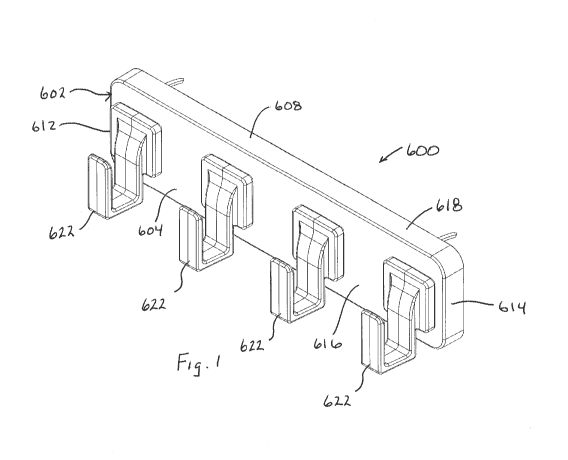
[0031] Referring to Figs. 1-3, one embodiment of a hook rail assembly 600
is
shown and includes an elongated rail member 602 having front 604, back 606,
top 608,
bottom 610, left 612 and right 614 sides. The elongated rail member as a
primary body
portion 616 surrounded by a peripheral rim portion 618 that extends rearwardly
the define a
recess 620 at the back side of the rail member. By way of example, the rail
member may
be of molded plastic construction and monolithic in form, but variations are
possible. For
example, the primary body portion 616 and the rim portion 618 may be formed
separately
and connected together, enabling a common rim portion to be used in
combination with a
number of different body portions (e.g., body portions with different numbers
of hooks
and/or body portions with differing graphic features). Forming the base member
of plastic
may facilitate more high end and detailed finishes. However, the rail member
may also be
formed of materials other than plastic.
[0032] The front side of the rail member 602 includes multiple protruding
hook
members 622. Here the hook members connect substantially along the height of
the rail
member and protrude forward, but other variations are possible. The hook
members 622
are formed separately from and connected to the rail member, but hook members
formed
monolithic with the rail member are also contemplated.
[0033] A plurality of anchor components (here just two) 628 are connected
at the
back side of the rail member, within the recess 620. Each anchor component 628
may be
of metal plate construction and includes a base plate 630 having front, back,
top, bottom,
left and right sides, and at least one wall penetrating retainer 632 extending
rearwardly
from the base plate and having a downwardly curved configuration. Each anchor
component is formed separate from the rail member 602 and is attached thereto
at the back
side utilizing cooperating structural features on each of the anchor component
and the rail
member. Each wall penetrating retainer includes a wall penetrating extent 632A
that that
protrudes rearwardly of a wall mount plane 606A of the rail member and has a
downwardly
curved configuration. In particular, the wall penetrating extent may be
arcuate in
4
CA 03000959 2018-04-04
WO 2017/078840 PCT/US2016/050101
configuration, where a center 632B of the radius of curvature R632 of the wall
penetrating
extents 632A is below and rearward of the bottom of the base plate 630 (per
Fig. 13) so as
to be located at the bottom, rear corner or edge of the rail member 602 (per
Fig. 2) once the
anchor component is installed on the rail member so that the bottom rear
corner can best
act as the pivot line for anchor installation into a wall 12 (per Figs. 15 and
16) as pressure P
is applied to the front side or the rail member to pivotally rotate the wall
penetrating extents
of the retainers into the wall and achieve the installation/mounting of the
hook rail
assembly on the wall. This geometry minimizes the energy and force required to
insert the
retainers, minimizes damage to the wall and results in small wall surface
perforations when
the hook rail assembly is removed from the wall 12.
[0034] As best seen in Figs. 4-7, the back side of the rail member 602
may include
features to create an anchor seating arrangement 640 for each of the anchor
components
628. The anchor seating arrangement retains the anchor component to the rail
member in a
desired location and orientation. In the illustrated embodiment, each anchor
seating
arrangement 640 includes spaced apart ribs 642, 644 with respective rearwardly
facing
distal edges 646, 648. The distal edge of rib 642 defines a recessed slot 650
and the distal
edge of the rib 644 defines a recessed slot 652, where the two slots 650, 652
are aligned to
receive and support the base 630 of the anchor component 628. The rib portions
at the
sides of the slots help to position and retain the anchor components against
lateral or
rotational movement during assembly. As shown, the ribs 642, 644 run
substantially
parallel to each other. Rib 654 interconnects with and runs substantially
perpendicularly
upward from the rib 642, and rib 656 interconnects with and runs substantially
perpendicularly downward from the rib 644. Thus, the ribs 654 and 656 extend
in
substantially opposite directions.
[0035] As will be described in further detail below, the wall penetrating
retainer
632 of the anchor components extends from the base and has an initial forward
progression. To accommodate this configuration, a distal edge 658 of the rib
654 is
recessed per slot 660 relative to the distal edge of the rib 642 in slot 650.
On the other
hand, the distal edge 662 of the rib 656 is not recessed relative to the
distal edge of the rib
644 in slot 652. Thus, the anchor component 628 can only be seated in the
seating
arrangement with the wall penetrating retainer 632 positioned by the rib 654.
This
configuration helps assure that the anchor components are always installed to
the rail
member in a specific, desired orientation.
CA 03000959 2018-04-04
WO 2017/078840
PCT/US2016/050101
[0036] In
terms of fixing the anchor components to the rail member, each anchor
component includes a mount opening 670 in its base 630, and each seating
arrangement
640 includes a mount hole 672 that is aligned with the mount opening 670. A
screw or
other fastener 674 passes through the mount opening 670 and into the mount
hole 672 to
secure the anchor component to the rail member, with a head of the screw
engaged with the
rear side of the anchor component base 630. As seen in Figs. 7 and 8, each
hook member
622 includes a rearwardly protruding boss 676 positioned within the rail
member mount
hole 672, where the boss 676 includes a passage 678. Upon assembly, the
threaded end of
the screw engages the passage 678 in order to secure both the anchor component
and the
hook member to the rail member.
[0037] As seen
in Figs. 8-11, the front side of the each mount hole 672 includes a
keyed configuration and the hook member boss 676 includes a similar keyed
configuration
to assure that the boss 676 can only be inserted into the mount hole 672 in a
specified,
desired orientation. The specified orientations of the mount bosses of all the
hooks may be
matched to assure similar hook member orientation on the rail member. In the
illustrated
embodiment the keyed configuration of the mount hole 672 is formed by a
central round
hole with upper and lower slot extensions 680 and 682, where a width W1 of the
upper slot
extension 680 is greater than the width W2 of the lower slot extension 682.
The keyed
configuration of the mount boss 676 includes a central round projection with
upper and
lower rib extensions 684 and 686, where a width W3 of the upper rib extension
684 is
greater than the width W4 of the lower rib extension 686. The width W3 of
upper rib
extension 684 is sized to fit within the upper slot extension 680, but not the
lower slot
extension 682. The widths of the upper and lower parts of the slot and rib
extensions could
be reversed, and other keyed configurations could also be used.
[0038]
Notably, the anchor components 628 utilized in connection with the hook
rail assembly 600 are configured to enable straightforward mounting of the
hook rail
assembly to a wall. In particular, and referring to Figs. 12-14, the anchor
component 628
includes a base 630 having front sides. In the illustrated configuration the
base 630 is
formed by a base plate (e.g., metal plate), the front side and back side are
formed by the
substantially planar front and rear surfaces of the base plate, and the top
side, bottom side,
left side and right side are formed by respective edges of the base plate. It
is recognized
that different configurations for the base 630 are possible.
6
CA 03000959 2018-04-04
WO 2017/078840 PCT/US2016/050101
[0039] A wall penetrating retainer 632 extends from the base and has a
rearwardly
protruding wall penetrating extent 632A with a primarily downwardly curved
configuration
as will be described in greater detail below. In the embodiment of anchor
component 628,
the wall penetrating retainer 632 is formed monolithic with the plate material
of the base
plate (e.g., utilizing a progressive stamping operation). In the illustrated
anchor component
628, the retainer 632 is formed by an appropriately bent portion of metal
plate and departs
from a side edge of the base plate.
[0040] In one implementation, the metal plate may be cold rolled alloy
sheet steel
(e.g., AISI 4130 per ASTM A506/507) with a thickness of between about 0.040
inches and
about 0.052 inches (e.g., no more than 0.052 inches), and the resulting anchor
component
may have a tensile yield strength of no less than 160 KSI and a minimum
elongation of 3%.
By making use of this ultra-high strength steel a thinner plate material can
be utilized to
achieve a desired load rating, enabling reduced cross-sectional size of the
wall penetrating
retainers in order to reduce required insertion force and minimize wall
damage. The
elongation characteristic assures adequate ductility after hardening.
[0041] Referring now primarily to Fig. 17, in certain embodiments, each
wall
penetrating retainer (here identified as 28) departs the base (here identified
as 14) with an
initial forward progression reflected by angle 01 and then turns back (e.g.,
with the
illustrated relatively sharp curve) to define a rearward and downward
progression along the
wall penetrating extent (here identified as 29). By way of example, angle 01
(e.g., taken
relative to a plane parallel to a mount plane 41 at the back side of the base)
may be between
about 3 degrees and about 30 degrees (e.g., between about 10 degrees and about
20 degrees
or between about 15 degrees and about 25 degrees), though variations are
possible. The
initial forward progression can be achieved by a slight forward bend in the
entire top edge
of the base as shown, or can be achieved by having only the retainers bend
forward as they
leave the top edge of the base plate. This forward progression feature is
advantageous
because it provides clearance for a generous bend retainer radius at the
juncture of the
retainer and the base plate to prevent stress cracking at this point of
maximum bending
load. In this regard, the initial portion of each wall penetrating retainer 28
that is forward
of the back side of the base curves forward and then curves rearward as shown,
and a
radius of curvature at every point along the initial portion may no less than
125% (e.g., no
less than 100%) of the plate thickness.
7
CA 03000959 2018-04-04
WO 2017/078840 PCT/US2016/050101
[0042] In order to facilitate installation of a hook rail assembly, the
wall penetrating
retainers of the anchor components can also be configured with other
advantageous
features.
[0043] For example, to facilitate manual wallboard penetration and
passage without
tools, utilizing thumb force only (e.g., applied at the thumb capture zones),
the wallboard
penetrating retainers 28 may be formed with a relatively smooth external
surface finish
(e.g., achieved by polishing, painting or plating). In this regard, the
surface of the
wallboard penetrating retainers 28 can be manufactured with or modified to a
maximum
average surface roughness of about 20 inch (e.g., in some cases a maximum
average
surface roughness of about 15 inch). In one implementation, just the
wallboard
penetrating extent of each wallboard penetrating retainers is worked,
processed or
otherwise formed to achieve this desired low surface roughness feature in
order to reduce
manufacturing cost. The latter implementation would reduce install force but
maintain
friction on the rougher portions of the penetrating retainer to resist removal
forces. The
retainers may have a polished surface finish and/or a plated surface finish
and/or a painted
finish and/or a lubricant (e.g., Teflon) incorporated into the surface finish.
[0044] Referring to Figs. 17 and 18, the distal end 28' of each wallboard
penetrating retainer 28 may include a pointed tip that is shaped to provide a
point 36 when
viewed in cross-section taken along a vertical plane running along a length of
the wallboard
penetrating retainer, where the point 36 is defined by a bevel 38 at a bottom
side of the
distal end of the wallboard penetrating retainer. In particular, in the
illustrated side
elevation it is seen that the wall penetrating extent 29 includes a concave
curved surface 43
separated form a convex curved surface 45, and lateral and opposed side
surfaces 47 that
are substantially planar and that extend between the convex curved surface and
the concave
curved surface. The bevel 38 extends from the concave surface 43 toward the
point 36 and
little or no bevel extends from the convex surface 45 toward the point 36, to
thereby place
the point 36 closer to the convex surface of the wall penetrating extent. This
type of
beveled point is advantageous because the applicants have discovered that
including a
bevel at the top side of the wallboard penetrating retainer disadvantageously
creates a
reaction force with the wallboard material that tends to cause the bottom side
of the base
plate to be pivoted out away from the front surface of the wallboard. Side
bevels 49 may
also be optionally incorporated to achieve the point 36 as shown. In one
implementation, a
lateral width W36 of the point is no more than 35% of a lateral width W29 of a
major
8
CA 03000959 2018-04-04
WO 2017/078840 PCT/US2016/050101
portion of the wall penetrating extent, and a thickness T36 of the point is no
more than
about 40% of a thickness T29 of the major portion of the wall penetrating
extent.
[0045] In this regard, proper sizing of the wallboard penetrating
retainer(s) can also
be used to achieve more user friendly performance of an anchor component. In
particular,
per Fig. 19, in some implementations when the hook rail assembly is installed
at the front
surface of the wallboard, the distal ends 28' of the wallboard penetrating
retainers 28 may
be positioned proximate to a wallboard rear surface 12B without passing
through the rear
surface. In some arrangements of this type, the distal end 28' of the
wallboard penetrating
retainer actually contacts an internal side 42 of the paper layer 44 that
defines the rear
surface of the wallboard but, again, does not pass through the paper layer 44.
The distal
end of the wallboard penetrating retainer may even cause a localized rearward
protrusion
46 in the paper layer 44 at a point of contact with the paper layer but,
again, without
passing through the paper layer 44. Arrangements of this type, in which the
wallboard
penetrating retainer is in contact with or proximate the paper layer 44
defining the rear
surface 12B without passing through that paper layer are advantageous in that
applicants
have discovered that it can take five pounds or more of additional force to
install if the
distal ends of the retainers must pass through rear paper layer 44 in order to
achieve final
anchor component seating position. Of course, in some embodiments the
retainers could
be longer and pierce the back paper layer of the wallboard.
[0046] In one example, low insertion forces for the retainer(s) of a
given hook rail
assembly may be achieved where the retainers have pointed distal ends as
described above
and a generally uniform cross-section along the remainder of the wall
penetrating extent of
the retainer, where an area of the cross-section is no more than about 2.5
mm2. In one
example, in the case retainers of rectangular cross-section, the main segment
of the wall
penetrating extent of each retainer may be on the order of 0.042 inches by
0.068 inches
(e.g., 0.042 inches thick and 0.068 inches wide), resulting in a cross-
sectional area of about
0.00286 in2 (about 1.845 mm2). In another example, the main segment of the
wall
penetrating extent may have a rectangular cross-section on the order of 0.050
inches by
0.075 inches (e.g., 0.050 inches thick and 0.075 inches wide), resulting in a
cross-sectional
area of about 0.00375 in2 (about 2.419 mm2). It may be advantageous (e.g., for
the
purpose of ease of install and/or for the purpose of limiting wall damage) to
assure that the
total retainer cross-sectional area (e.g., the combined cross-sectional area
of the two
retainers of hook rail assembly 600) is no more than about 5 mm2 (about 0.008
square
9
CA 03000959 2018-04-04
WO 2017/078840 PCT/US2016/050101
inches, or in some cases no more than about 6 mm2), where the cross-section of
each wall
penetrating extent of the retainer is taken perpendicularly to a lengthwise
axis 292 (Fig. 17)
of the retainer (which axis is curved like the retainer) and is taken at any
location along a
length of the wall penetrating extent 29 that will embed within a wall (e.g.,
a cross-section
in any of planes 294, 296 or 298). This arrangement facilitates installation
and reduced
wall hole size that must be repaired after removal.
[0047] Referring now to Figs. 20-23, another embodiment of a hook rail
assembly
100 is shown and includes an elongated rail member 102 having front 104, back
106, top
108, bottom 110, left 112 and right 114 sides. The elongated rail member as a
primary
body portion 116 surrounded by a peripheral rim portion 118 that extends
rearwardly the
define a recess 120 at the back side of the rail member. The front side of the
rail member
102 includes multiple protruding hook members 122. Here the hook members
connect at
the bottom side of the rail member and protrude forward, but other variations
are possible.
Likewise, the hook members 122 are of monolithic construction with the rail
member, but
could be formed separately and attached.
[0048] A plurality of anchor components (here just two) 128 are connected
at the
back side of the rail member, within the recess 120. Each anchor component 128
may be
of metal plate construction and includes a base plate 130 having front, back,
top, bottom,
left and right sides, and at least one wall penetrating retainer 132 extending
rearwardly
from the base plate and having a downwardly curved configuration similar to
that of the
embodiments described above. Each anchor component is formed separate from the
rail
member 102 and is attached thereto at the back side utilizing cooperating
structural features
on each of the anchor component and the rail member. The anchor components 128
may
be of similar configuration to anchor components 628 described above.
[0049] The back side of the rail member includes an anchor seating
arrangement
140 for each of the anchor components. The anchor seating arrangement retains
the anchor
to the rail member. In the illustrated embodiment, each anchor seating
arrangement 140
includes a set of vertically and horizontally spaced apart slots 142 into
which opposite
corners of the anchor component 128 are positioned when the anchor component
is in a
seated position (e.g., the position shown in Fig. 21). Here each slot 142 is
formed by bar
member 144 with an L-shaped end profile, but other configurations are
possible. Each
anchor seating arrangement 140 also includes a circumferential protrusion 146
that passes
through a circumferential opening of the base plate 130 of its respective
anchor component
CA 03000959 2018-04-04
WO 2017/078840 PCT/US2016/050101
128. This cooperative arrangement enables the anchor component 128 to be
attached to the
rail member by initially placing the anchor component onto the protrusion 146
with the
anchor in an initial position in which the base plate does not engage the
slots (e.g., the
position represented by dashed line anchor form 128' in Fig. 22). The anchor
component
can then be rotated about the protrusion 146 (in the counter-clockwise
direction of arrow
150 in Fig. 22) in order to move the anchor component into its seated
position. As seen in
illustrated embodiment of Fig. 21, the orientation of the slots of the two
seating
arrangements is opposite each other, so that one anchor component (the left in
Fig. 22)
would be rotated counter-clockwise to reach its seated position and the other
anchor
component (the right in Fig. 22) would be rotated clockwise to reach its
seated position.
[0050] In order to hold each anchor component in its seated position,
each anchor
seating arrangement 140 also includes at least one retention feature 152 that
engages with
the anchor component to inhibit rotation of the anchor component 128 from the
seated
position back to the initial position. In the illustrated embodiment the
retention feature 152
is formed by a short finger that extends from part of the rim portion 118 of
the rail member
and includes a curved or ramped surface portion 154 that interacts with the
anchor retainer
132. In particular, the anchor retainer 132 slides along the surface portion
154 during the
rotation of the anchor component into the seated position. When the retainer
132 clears the
finger, an edge 156 of the finger engages with an edge of the retainer 132 to
hold the
retainer in place. The finger 152 may flex slightly during this process.
Likewise, at least
some relative flex between each anchor component and its retention feature 152
may be
provided to enable the anchor component to be rotated from the seated position
to the
initial position.
[0051] Referring now to Figs. 24-31, another embodiment of a hook rail
assembly
200 is shown and includes an elongated rail member 202 having front 204, back
206, top
208, bottom 210, left 212 and right 214 sides. The elongated rail member as a
primary
body portion 216 surrounded by a peripheral rim portion 218 that extends
rearwardly the
define a recess 220 at the back side of the rail member. Anchor components 228
are of
similar configuration to anchor components 128, and anchor seating
arrangements 240 of
are of similar configuration to anchor seating arrangements 140 above.
[0052] The rail assembly includes a plurality of hook members 222. The
hook
members 222 are initially formed separately from and the attached to the rail
member 202.
For this purpose the rail member 202 includes a plurality of hook receiving
openings 260
11
CA 03000959 2018-04-04
WO 2017/078840 PCT/US2016/050101
through which a connecting end 270 of a hook member is positioned. In this
regard, in the
illustrated embodiment the through openings 260 and the hook members 222 are
respectively sized and shaped to enable the hook member to be connected into
the through
opening by inserting the connecting end 270 through the opening 260 at the
front side of
the rail and sliding the slot 262A to the top edge of the opening 260. The
lower flange 264
then deflects and snaps over the bottom edge of the opening 260. Once
installed, the
connecting end 270 of each hook member includes spaced apart upper and lower
retention
flanges 262 and 264 that extend beyond respective peripheral edges of the rail
member
through opening 260 (e.g., see Fig. 31). As seen in Figs. 28-30, the lower
flange 264 may
in part define a rail engaging lateral edge or corner 266 that can engage with
a lower
peripheral edge of the through opening to transfer weight of the hook onto the
rail member.
The corner 266 will also serve as a pivot about which the hook will attempt to
rotate when
loaded, in which case the upper flange 262 will engage with the back side of
the rail
member to prevent the hook from being pulled or rotated forwardly out of the
rail member.
[0053] Where the hook members are removable from the rail member, the
hook
members can be packed as separate pieces (e.g., laying down sideways in a
package that
also includes the rail member) in order to reduce space taken up by the
package and thus
reduce shipping costs.
[0054] Another embodiment of a hook rail assembly 300 is shown in Figs.
32-41
and includes an elongated rail member 302 having front, back, top, bottom,
left and right
sides. The elongated rail member as a primary body portion 316 surrounded by a
peripheral rim portion 318 that extends rearwardly the define a recess 320 at
the back side
of the rail member. Anchor components 328 are generally of similar
configuration to
anchor components 128 and 228, and anchor seating arrangements 340 have some
similar
features to anchor seating arrangements 140 and 240 above. In particular, each
anchor
seating arrangement 340 includes slots 342, bars 344 and a protrusion 346
engaged by an
opening in the anchor base plate. The seating arrangement 340 also includes a
plurality of
ribs 380 extending rearwardly on the rail member in the vicinity of the bars
344 that in part
define the slots 342 and that help guide the anchor component base plate into
the slot as the
anchor component is rotated into its seated position. The ribs 380 may have
tapered entry
edges 381 for this purpose. The ribs 380 toward the upper side of the anchor
component
also provide a strengthening of the rail member in the vicinity of the
location where
pressure will be applied during installation of the rail assembly into the
wall.
12
CA 03000959 2018-04-04
WO 2017/078840 PCT/US2016/050101
[0055] The seating arrangement 340 also includes a rearwardly projecting
feature
382 (here a pin-shaped member, though other shaped projections could be used)
that acts as
the anchor retention feature. Each base plate includes a further opening 384
that aligns
with the pin member 382 when the anchor component is in the initial position
so as to
enable the corner regions of the anchor component base plate to enter the
slots 342. When
the anchor component 328 is rotated into its seated position, the surface of
the base plate
slides over the pin (e.g., the upper end of the pin or other feature may be
ramped or tapered
for this purpose) until the edge of the base plate clears the pin 382 and
drops laterally
alongside the upper portion of the pin 382. The interaction of the pin 382 and
base plate
edge then inhibits rotation of the anchor component out of its seated position
under normal
operating conditions. Notably, each anchor component includes a set of spaced
apart
openings 384 so that the identical anchor component configuration can be used
for either a
seating arrangement with counter-clockwise anchor component seating or
clockwise
anchor component seating.
[0056] The hook members 322 are initially formed separately and then
attached to
the rail member 302. In this embodiment the through openings 360 of the rail
member are
surrounded by rib features 390 projecting rearwardly at the back side of the
rail member
that strengthen the rail member in the vicinity of hook connection. The hook
members 322
include a connecting end 370 and a hook end 372, where the connecting end is
adapted for
linear insertion through the rail member opening 360. In this regarding, the
connecting end
370 includes upper and lower retention fingers 374 and 376 that flex inward as
they
interact with the edges of the opening 360 when the connecting end is passed
from the front
side of the rail member through the opening 360. As retention tabs or flanges
378 and 379
on the fingers clear the back edge of the opening, the fingers flex back
outward so that the
tabs 378, 379 will extend beyond the perimeter of the opening to retain the
hooks on the
rail member (e.g., see Fig. 41).
[0057] It is to be clearly understood that the above description is
intended by way
of illustration and example only, is not intended to be taken by way of
limitation, and that
other changes and modifications are possible. For example, while the
illustrated hook rail
assemblies contemplate multiple hooks and multiple anchors connected to a rail
member, it
is recognized that a single anchor could be connected at the back side of a
single hook (e.g.,
a fashion hook) in a manner similar to that described above to achieve a hook
and anchor
13
CA 03000959 2018-04-04
WO 2017/078840
PCT/US2016/050101
assembly. Moreover, other variations of attachment of the anchor component(s)
to the rail
member are possible, such as overmolding or heat stacking or any other
suitable manner.
14