Note: Descriptions are shown in the official language in which they were submitted.
JOINT IMPLANTS AND METHODS
PRIORITY APPLICATION
[0001] This application claims the benefit of priority to U.S. Application
Serial
No. 62/254,282, filed November 12, 2015.
FIELD
[0002] The present disclosure relates to joint implants for promoting
bony in-growth
and associated systems and methods.
BACKGROUND
[0003] This section provides background information related to the
present disclosure,
which is not necessarily prior art.
[0004] Osteochondral lesions are a common injury to the ankle and knee
regions (as
well as other joints) that can be caused by traumatic injury (e.g., a severe
sprain).
Osteochondral lesions are injuries to the articular joint surface that affect
both the bone and
the cartilage surrounding the bone. Such lesions can be present at the ankle
joint, where the
talus meets the tibia, or at the sub-talar joint, where the talus meets the
calcaneous. In less
severe cases, osteochondral lesions may be treated by restricting activity and
simply allowing
the injured cartilage and bone to heal. However, some cases will require
surgical remedies.
Some surgical remedies include conventional bone and cartilage grafting,
debridement (i.e.
removing damaged cartilage and bone), or microfracture of the lesion. These
techniques may
be ineffective in treating larger lesions.
SUMMARY
[0005] This section provides a general summary of the disclosure, and
is not a
comprehensive disclosure of its full scope or all of its features.
1
CA 3005228 2019-07-31
CA 03005228 2018-05-11
WO 2017/083718
PCT/US2016/061627
10006] The
present inventors have recognized, among other things, that a problem to
be solved can include a solution for effective surgical treatment of large
cystic type-V lesions of
the talus. The present disclosure provides such a solution through an implant
intended for
insertion into and replacement of the damaged region of the talus bone and
cartilage that
promotes bony in-growth while also providing for an articulable joint surface.
Accordingly, the
present disclosure provides for a bone implant that can comprise a cylindrical
member and an
articulating member. The cylindrical member can extend along an implant axis
from a first end
to an opposed second end thereof. The cylindrical member can have a void
disposed therein
extending from the first end towards the second end. The cylindrical member
can comprise an
interconnected open-pore structure for promoting bone tissue in-growth. The
articulating
member can comprise an articulating portion and a core portion extending away
from the
articulating portion. The articulating member can be coupled to the
cylindrical member such
that the core portion extends into the void disposed in the cylindrical member
and the
articulating portion is positioned adjacent the first surface of the
cylindrical member and
extends radially outward from the implant axis to cover the first surface of
the cylindrical
member.
(0007] In
another example, the present disclosure provides for a system comprising a
first bone implant and a second bone implant. The first bone implant can
comprise a first
cylindrical member and a first articulating member. The first cylindrical
member can extend
.. along a first implant axis from a first end to an opposed second end
thereof. The first cylindrical
member can have a void disposed therein extending from the first end towards
the second end.
The first cylindrical member can comprise an interconnected open-pore
structure for
promoting bone tissue in-growth. The first articulating member can comprise an
articulating
portion and a core portion extending away from the articulating portion. The
first articulating
member can be coupled to the first cylindrical member such that the core
portion extends into
the void disposed in the first cylindrical member and the articulating portion
is positioned
adjacent the first surface of the first cylindrical member and extends
radially outward from the
implant axis to cover the first surface of the first cylindrical member. The
second bone implant
can comprise a second cylindrical member and an articulating portion. The
second cylindrical
2
CA 03005228 2018-05-11
WO 2017/083718 PCT/US2016/061627
member can extend along a first implant axis from a first end to an opposed
second end
thereof. The second cylindrical member can comprise an interconnected open-
pore structure
for promoting bone tissue in-growth. The outer diameter of the first
cylindrical member of the
first bone implant can be less than the outer diameter of the second
cylindrical member of the
second bone implant.
[0008] In another example, a method is provided that comprises
preparing bone
tunnels from outside of the bone to a point within the bone defect. These bone
tunnels may be
directed with the use of a guide that can contain a targeting arm on a multi-
planar positioning
jig. The target arm can be placed inside the joint at a position that is
optimized for placement
of the implant. The jig can then be positioned to contact a portion of the
same bone at a point
in which a small incision and bone tunnel can be created in order to access
the bone defect.
Bone tunnels can be created by placing guide wires and then drilling the bone
with cannulated
drills, reamers, or bone trephines once the guide wire is in place. If two
opposing implants are
prescribed, the bone tunnel for the second bone and implant can be drilled
through the initial
bone tunnel of the first bone. Also, if multiple implants are prescribed in
the second bone, the
corresponding bone tunnels can be drilled into the second bone by rotating the
joint and
repositioning the lesion and second implant site to be in-line with the first
bone tunnel in the
first bone. Additionally, multiple bone tunnels could be drilled in the first
bone by repositioning
the guide on the first bone and placing multiple guide wires and tunnels. The
bone tunnels in
the first bone may be the same size or slightly larger than the tunnel in the
second bone. This
can help make the insertion of the implant into the second bone easier.
Insertion devices can
assist with inserting the implants either through the bone tunnels or through
the joint space. It
is anticipated that final placement of the implants would occur through the
bone tunnels.
[0009] Further areas of applicability will become apparent from the
description
provided herein. The description and specific examples in this summary are
intended for
purposes of illustration only and are not intended to limit the scope of the
present disclosure.
3
CA 03005228 2018-05-11
WO 2017/083718
PCT/US2016/061627
BRIEF DESCRIPTION OF DRAWINGS
[0010] The drawings described herein are for illustrative purposes
only of selected
embodiments and not all possible implementations, and are not intended to
limit the scope of
the present disclosure.
[0011] FIG. 1A illustrates a perspective view of an exemplary bone implant
according to
at least one example of the present description.
[0012] FIG. 18 illustrates a perspective view of another exemplary
bone implant
according to at least one example of the present description.
[0013] FIGS. 2A, 2B and 2C are cross-sectional side views of bone
implants according to
at least one example of the present description.
[0014] FIG. 3 illustrates a perspective view of a bone implant
according to at least one
example of the present description.
[0015] FIG. 4 provides a side view of an implantable joint system
according to at least
one example of the present description.
[0016] FIG. 5 provides a side view of an implantable joint system according
to at least
one example of the present description.
[0017] FIG. 6 provides a side view of an implantable joint system
according to at least
one example of the present description.
[0018] FIG. 7A illustrates one exemplary guide for implanting a bone
implant.
[0019] FIG. 78 is a partial perspective view of the guide foot of FIG. 7A.
[0020] FIGS. 8A and 8B illustrate one exemplary method for implanting
bone implants.
[0021] FIG. 9 illustrates another exemplary method for implanting bone
implants.
[0022] FIGS. 10A and 108 illustrate an anterior-posterior view and a
medial-lateral view
of various examples of access points.
[0023] FIG. 11 illustrates another exemplary method for implanting bone
implants.
4
CA 03005228 2018-05-11
WO 2017/083718
PCT/US2016/061627
[0024] Corresponding reference numerals indicate corresponding parts
throughout the
several views of the drawings.
DETAILED DESCRIPTION
[0025] Example embodiments will now be described more fully with
reference to the
accompanying drawings.
[0026] The present disclosure provides for an implant for insertion
into and
replacement of the damaged region of a talus bone and adjacent cartilage, the
implant
promoting bony in-growth while also providing for an articulable joint
surface. Such implants
can be used for surgical treatment of large, cystic lesions of the talus bone
such as type-V
lesions.
[0027] As illustrated in Figure 1A-113, the bone implant 100 (or 100'
in all following
instances) can be implanted in the talus in areas where osteochondral lesions
are present. The
bone implant 100 can comprise a cylindrical member 102 and an articulating
member 104. The
cylindrical member 102 can extend along an implant axis 106 from a first end
108 to an
opposed second end 110. The cylindrical member 102 can have a void 112
disposed therein
that extends from the first end 108 towards the second end 110. The
articulating member 104
can comprise an articulating portion 114 and a core portion 116 extending away
from the
articulating portion. The articulating member 104 can be coupled to the
cylindrical member
102 such that the core portion 116 extends into the void 112 disposed in the
cylindrical
member 102 and the articulating portion 114 is positioned adjacent the first
end 108 of the
cylindrical member 102. The articulating portion 114 can extend radially
outward from the
implant axis 106 to cover the first end 108 of the cylindrical member 102. The
articulating
member 104 can be monolithic. The articulating member 104 can comprise at
least one of
polyethylene, cobalt chrome, ceramic, hydrogel, polyurethane, silicone, or
PEEK.
[0028] The articulating portion 114 can provide a surface to support
articulation of a
first bone (into which the implant 100 is implanted) and a second bone that is
adjacent to the
first bone. As illustrated in Figure 1, the articulating portion 114 can have
a generally planar
articulating surface 118. As illustrated in Figure 2A, the articulating
portion 214 of implant 200
5
CA 03005228 2018-05-11
WO 2017/083718 PCT/US2016/061627
can have an articulating surface 218a that is at least partially concave
relative to a plane
transverse to the implant axis 106. Additionally or alternatively, as
illustrated in Figure 28, the
articulating portion 214 of implant 200' can have an articulating surface 218b
that is at least
partially convex relative to a plane transverse to the implant axis 206.
Additionally, the void
212 disposed in the cylindrical member 202 and, additionally, the core portion
216 of the
articulating member 204, can extend to the second end 210 of the cylindrical
member 202.
[0029] In an additional or alternative example illustrated in Figure
18, the implant 100'
can have a helical thread 120 extending across at least a portion of the
length of the cylindrical
member 102. The helical thread 120 can be solid. The helical thread 120 can
provide for
benefits such as, for example and without limitation, initial stability,
insertion options, and the
like. In another additional or alternative example illustrated in Figure 2C,
the implant 200" can
have a threaded member 220 coupled to the second end 210 of the cylindrical
member 202.
The threaded member 220 can be formed integrally with the cylindrical member
202, can be
engageable with the cylindrical member 202, or can be a separate component
from cylindrical
member 202. The diameter of the threaded member DA can be greater than a
diameter of the
implant DB. Either or both of the helical thread 120 and the threaded member
220 can be
combined with any example of an implant disclosed herein.
[0030] The cylindrical member 102, 202 can comprise, in some examples,
a material
having interconnected open-pore structure for promoting bone tissue in-growth.
The material
can be at least one of stainless steel, titanium, titanium alloy, tantalum,
polyether ether ketone
(PEEK) and cobalt-chromium alloy. One suitable material comprises OsseoTi
porous metal
marketed by Zimmer Biomet (Warsaw, IN). OsseoTi comprises Ti6AI4V and can have
a porous
structure that generally mimics the porous structure of human cancellous bone.
OsseoTi can
be highly biocompatible and can have excellent corrosion resistance.
Additionally or
alternatively, the material can comprise Trabecular Metal, also marketed by
Zimmer Biomet
(Warsaw, IN). Such a material may be formed from a reticulated vitreous carbon
foam
substrate which can be infiltrated and coated with a biocompatible metal, such
as tantalum, by
a chemical vapor deposition ("CVD") process in the manner disclosed in detail
in U.S. Patent No.
5,282,861 and in Levine, B.R., et al, "Experimental and Clinical Performance
of Porous
6
Tantalum in Orthopedic Surgery", Biomaterials 27 (2006) 4671-4681. Such
structures can be
particularly suited for contacting bone and/or soft tissue, and in this
regard, can be useful as
bone substitutes and other implants and implant components that are receptive
to cell and
tissue ingrowth, for example, by allowing and promoting bony tissue or other
tissue growth into
the porous structure over time to enhance fixation (e.g., osseointegration)
between the implant
and surrounding bodily structures. According to various examples, the
cylindrical member 102,
202 can comprise biologics such as demineralized bone matrix (DBM), bone
morphogenetic
proteins (BMP) and antibiotics. According to other features, the cylindrical
member 102, 202
can comprise at least one of an anti-infective agent, an osteoconductive
agent, an autologous
blood product, a hydrogel, autologous cells, allogenic cells, peptides, and a
bulk allograft.
[0031] As illustrated in Figure 3, the present disclosure also
provides for a bone implant
300 that can comprise a cylindrical member 302 that can extend along an
implant axis 306 from
a first end 308 to an opposed second end 310 thereof. Cylindrical member 302
can comprise
any material or combination of materials described above with reference to
cylindrical member
102, 202. The region proximate the first end 308 of the cylindrical member 302
can comprise
an articulating portion 314. The articulating portion 314 can be formed
monolithically with the
cylindrical member 302. The articulating portion 314 can comprise a non-porous
variant of the
material of the cylindrical member 302 such as, for example and without
limitation, a titanium
alloy, a tantalum alloy, and the like. Alternatively, the articulating portion
314 can be formed
from a different material than the cylindrical member 302. For example, the
articulating
portion 314 can comprise cobalt chrome or other suitable metals. In some
examples, the
articulating portion 314 can comprise an articulating surface 318 that can
comprise a polished
metal or metal alloy. A polished articulating surface 318 can aid in
articulation of the bone
implant with less friction with adjacent surfaces (e.g., another implant or
adjacent bone), and
result in a longer lifetime of the implant.
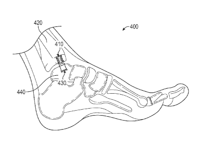
[0032] As illustrated in Figure 4, the present disclosure also
provides for a system 400
comprising a first implant 410 for implantation into a first bone 420 of a
joint and a second
implant 430 for implantation into a second bone 440 of a joint. In one
example, the system can
7
CA 3005228 2019-07-31
CA 03005228 2018-05-11
WO 2017/083718 PCT/US2016/061627
be used with an ankle. Here, the first bone 420 can be a talus and the second
bone 440 can be
either a calcaneous or a tibia. In one example, an implant or a system
comprising two implants
can facilitate articulation of the talus with the calcaneous (in which case
the talus implant will
be positioned in the lower region of the talus). In another example, an
implant or a system
comprising two implants can facilitate articulation of the talus with the
tibia (in which case the
talus implant will be positioned in the upper region of the talus). The first
implant 410 and the
second implant 430 can each comprise any of the implants described above with
reference to
Figures 1-3. Further, the first implant 410 and the second implant 430 can be
either the same
as or different from each other.
[0033] In one example, the articulating surface 412 of the first implant
410 can be at
least partially convex and the articulating surface 432 of the second implant
430 can be at least
partially concave (or vice-versa) in order to aid in more effective
articulation of the implants
with respect to one another. In other examples, one or both of the
articulating surfaces 412,
432 can be generally planar. Where the first and second bone implants 410, 430
at least
partially directly oppose one another and articulate with respect to one
another, one of the
first or second articulating surfaces 412, 432 can comprise metal and the
opposing first or
second articulating surface can comprise polyethylene. Alternatively, each of
the opposing first
and second articulating surfaces 318, 338 can comprise metal, or each can
comprise
polyethylene.
[0034] Although Figure 4 illustrates that articulating surface 412 of the
first implant 410
directly opposes the articulating surface 432 of the second implant 430, this
need not be the
case. As illustrated in Figure 5, the articulating surface 512 of the first
implant 510 can be at
least partially offset from the articulating surface 532 of the second implant
530, such that each
implant at least partially articulates in direct contact with bone or
surrounding tissue.
Additionally or alternatively, the bones of the foot could be rotated relative
to one another to
achieve alignment of the implants 520, 530 to ensure an optimal therapeutic
result.
[0035] In various other examples, three, four, five or potentially
more implants can be
used in an implantable system. As illustrated in Figure 6, a system 600 can
comprise, e.g., five
bone implants: two implants 602, 604 in a first bone of the joint, and three
implants 606, 608,
8
CA 03005228 2018-05-11
WO 2017/083718 PCT/US2016/061627
610 in an opposing bone of the joint. In this example, multiple implants can
be prepared
through a single access hole. As one example, implants 606 and 608 can be
prepared through
the access hole associated with implant 602, and implant 602 subsequently
prepared. As
another example, implants 608 and 610 can be prepared through the access hole
associated
with implant 604, and implant 604 subsequently prepared.
[0036] In another example, a drill guide 700 can be provided. The
drill guide 700 can
comprise a main body 702, a slotted sleeve 704 and a foot 708. The main body
702 can be
angularly adjustable to rotate about axis 712 to change the angle between the
foot 708 and the
sleeve 704. The main body 702 can be angularly adjustable to rotate about axis
714 to change
the angle between the foot 708 and the sleeve 704 in a second plane. The
sleeve 704 can
comprise two slotted telescoping sleeves to facilitate adjustability and
removal from guide pin
706 after the guide pin 706 is placed into bone. The foot 708 can have an
insertion end that is
open and slotted. The foot 708 can facilitate identification of the defect in
the native bone.
The guide foot can have a dimensions a and b that can each be larger than the
corresponding
implant dimensions to, for example, ensure proper spacing between multiple
guide pins and
holes for implants.
[0037] In another example, at least Figures 8A, 88, 9, and 11
illustrate one method for
implanting bone implants. A drill having a first diameter D1 can make a first
bore through a first
bone of a joint and into the second bone of a joint opposite the first bone. A
second drill having
a second diameter 02 that is greater than the first diameter can make a
counter bore into the
first bone. The second implant can have a first diameter D1 corresponding to
the first drill and
can be inserted into a second bone of a joint. The first implant can have a
second diameter 02
corresponding to the second drill and can be inserted into the first bone
subsequent to
insertion of the first implant. In one example shown in Figures 8A and 88, the
first implant 810
can be implanted in the first bone that can be a talus 820 and the second
implant 830 can be
implanted in the second bone that can be a tibia 840. In another example shown
in Figure 9,
the first implant 910 can be implanted in first bone that can be a tibia 920
and a second implant
930 can be implanted in a second bone that can be a talus 940. In another
example shown in
Figure 11, the first implant 910 can be implanted in first bone that can be a
tibia 920 and a
9
CA 03005228 2018-05-11
WO 2017/083718 PCT/US2016/061627
second implant 930 can be implanted in a second bone that can be a talus 940.
As illustrated in
Figures 1.0A and 108, the number and examples of implant access strategies are
numerous and
one or more access points can be used to implant one or more implants. Hole
placements in
Figure 10A and 1013 are exemplary only and are not intended to be limiting.
[0038] A method for implanting a bone implant, such as those configurations
shown in
at least Figures 4, 8A, 88, 9, and 10, can comprise placing wires or drill
holes from the first bone
to the second bone. To ensure clarity of disclosure, in the following
disclosure the tibia is the
first bone and the talus is the second bone (unless specified otherwise),
however any of the
recited combination disclosed herein or known in the art can be employed using
the methods
described herein. The wires or drill holes can be placed over areas of
articular defects to be
treated. The articular defect can be on either the first bone or the second
bone of the joint
(e.g., the tibia or the talus). The guide wire can be inserted into the joint
space through the
tibia. A first hole can be drilled with a cannulated drill through the tibia
to the joint space. The
wire and drill can be removed. The location of the talus defect can be
maintained in line with
the tibia hole and a second solid drill can drill into the talus to set the
depth of the second
implant. The depth of the second implant can be, for example, from about lOmm
to about
20mm. Optionally, a guide wire can be placed across the joint space and into
the talus.
Optionally, instead of the solid drill, the cannulated drill can drill through
the tibia and into the
talus to set the depth for an implant height for the second implant.
[0039] In an example where more than one implant is needed and as
illustrated in
Figure 6, a second guide pin can be used to facilitate placement of a second
pin. The same
guide or a second guide can be used for the placement of the second pin.
Additionally or
alternatively, the same tibial hole can be used to facilitate placement for a
plurality of talus
implants. In one example illustrated in at least Figure 5, the foot, with
guide pins removed, can
.. be rotated to align a location for the second talus hole with the tibial
hole and the guide. Then,
the guide pin can be placed and the second talus hole can be drilled at the
aligned location.
[0040] In another example, a modular cutter or a reamer can be
inserted into the joint
space from a small incision. A cutter can be attached to a guide pin and can
cut bone tissue to a
desired depth in the talus and the tibia. A two-sided cutter can be used or a
one-sided cutter
can be used, requiring repositioning for each hole. Such methods are disclosed
in U.S. Patent
No. 9,301,766.
[0041] In another example, a drill guide, such as the drill guide 700
illustrated in Figures
7A and 7B, comprising a drill over a pin 706 or wire can be employed. A first
drill 704a can be
used to drill a first hole through the talus and into the tibia. The second
drill 704b can have a
second diameter that is greater than the first diameter and can drill into the
tibia only. This
method allows additional fixation on the tibial implant using, for example,
one of the implants
of Figures 18 and 2C.
[0042] In another example, the joint between the calcaneous and the
talus can be
prepared and implanted similar to the talus/tibia examples above. If needed, a
guide can be
employed. The joint can be accessed and lesions identified. A guide wire can
be placed. An
implant hole or holes can be drilled. Here, the calcaneous can be over drilled
through the first
cortex if an implant with adjustment or additional fixation is to be employed
using, for example,
one of the implants of Figures 1B and 2C.
Various Notes & Examples
[0043] Example 1 is a bone implant, comprising: a cylindrical member
that can extend
along an implant axis from a first end to an opposed second end thereof. The
cylindrical
member can have a void disposed therein that can extend from the first end
towards the
second end. The cylindrical member can comprise an interconnected open-pore
structure for
promoting bone tissue in-growth. An articulating member can comprise an
articulating portion
and a core portion extending away from the articulating portion. The
articulating member can
be coupled to the cylindrical member such that the core portion extends into
the void disposed
in the cylindrical member. The articulating portion can be positioned adjacent
the first surface
of the cylindrical member and can extend radially outward from the implant
axis to cover the
first surface of the cylindrical member.
[0044] In Example 2, the subject matter of Example 1 optionally
includes wherein the
articulating member can be monolithic.
11
CA 3005228 2019-07-31
CA 03005228 2018-05-11
WO 2017/083718
PCT/US2016/061627
[0045] In Example 3, the subject matter of any one or more of Examples
1-2 optionally
include wherein the articulating member comprises at least one of polyethylene
and cobalt
chrome.
[0046] In Example 4, the subject matter of any one or more of Examples
1-3 optionally
include wherein an articulating surface of the articulating portion can be at
least partially
concave relative to a plane transverse to the implant axis.
[0047] In Example 5, the subject matter of any one or more of Examples
1-4 optionally
include wherein an articulating surface of the articulating portion can be at
least partially
convex relative to a plane transverse to the implant axis.
[0048] In Example 6, the subject matter of any one or more of Examples 1-5
optionally
include wherein the cylindrical member comprises at least one of a titanium
alloy and a
tantalum alloy.
[0049] In Example 7, the subject matter of any one or more of Examples
1-6 optionally
include wherein the void disposed in the cylindrical member extends to the
opposed second
surface, and wherein the elongate core of the articulating member extends to
the opposed
second surface of the cylindrical member.
[0050] Example 8 is a system comprising a first bone implant and a
second bone
implant. The first bone implant can comprise a first cylindrical member having
an outer
diameter and can extend along an implant axis from a first end to an opposed
second end
.. thereof. The first cylindrical member can have a void disposed therein
extending from the first
end towards the second end. The first cylindrical member can comprise an
interconnected
open-pore structure for promoting bone tissue in-growth. The first bone
implant can further
comprise a first articulating member that can comprise an articulating portion
and a core
portion extending away from the articulating portion. The first articulating
member can be
coupled to the first cylindrical member such that the core portion extends
into the void
disposed in the first cylindrical member. The articulating portion can be
positioned adjacent
the first surface of the first cylindrical member and can extend radially
outward from the
implant axis to cover the first surface of the first cylindrical member. A
second bone implant
12
CA 03005228 2018-05-11
WO 2017/083718 PCT/US2016/061627
can comprise a second cylindrical member that can have an outer diameter and
can extend
along an implant axis from a first end to an opposed second end thereof. The
second cylindrical
member can comprise an interconnected open-pore structure for promoting bone
tissue in-
growth. The second bone implant can further comprise an articulating portion
proximate the
first end of the second cylindrical member. The outer diameter of the first
cylindrical member
of the first bone implant can be less than the outer diameter of the second
cylindrical member
of the second bone implant.
[0051] In Example 9, the subject matter of Example 8 optionally
includes wherein either
or both of the first cylindrical member and the second cylindrical member can
comprise at least
one of titanium, a titanium alloy, tantalum, and a tantalum alloy.
[0052] In Example 10, the subject matter of any one or more of
Examples 8-9 optionally
include wherein the articulating portion and the second cylindrical member of
the second bone
implant can be monolithic.
[0053] In Example 11, the subject matter of any one or more of
Examples 8-10
optionally include wherein the articulating portion of the second bone implant
can comprise a
non-porous metal or a metal alloy.
[0054] In Example 12, the subject matter of any one or more of
Examples 8-11
optionally include wherein the second cylindrical member further comprises a
void disposed
therein that can extend from the first end towards the second end; and wherein
the second
implant further comprises a second articulating member comprising the
articulating portion
and a core portion that can extend away from the articulating portion, wherein
the second
articulating member can be coupled to the second cylindrical member such that
the core
portion can extend into the void disposed in the second cylindrical member and
the articulating
portion can be positioned adjacent the first surface of the second cylindrical
member and can
extend radially outward from the implant axis to cover the first surface of
the second cylindrical
member.
[0055] In Example 13, the subject matter of any one or more of
Examples 8-12
optionally include wherein an articulating surface of the articulating portion
of the first
13
CA 03005228 2018-05-11
WO 2017/083718 PCT/US2016/061627
articulating member can be at least partially concave relative to a plane
transverse to the
implant axis.
[0056] In Example 14, the subject matter of Example 13 optionally
includes wherein an
articulating surface of the articulating portion of the second articulating
member can be at least
partially convex relative to a plane transverse to the implant axis.
[0057] In Example 15, the subject matter of any one or more of
Examples 8-14
optionally include wherein an articulating surface of the articulating portion
of the first
articulating member can be at least partially convex relative to a plane
transverse to the
implant axis.
[0058] In Example 16, the subject matter of Example 15 optionally includes
wherein an
articulating surface of the articulating portion of the second articulating
member can be at least
partially concave relative to a plane transverse to the implant axis.
[0059] In Example 17, the subject matter of any one or more of
Examples 8-16
optionally include wherein at least one of the first the articulating member
and the second
articulating member can be monolithic.
[0060] In Example 18, the subject matter of any one or more of
Examples 8-17
optionally include wherein at least one of the first the articulating member
and the second
articulating member can comprise at least one of polyethylene and cobalt
chrome.
[0061] In Example 19, the subject matter of any one or more of
Examples 8-18
optionally include wherein the cylindrical member can comprise at least one of
a titanium alloy
and a tantalum alloy.
[0062] In Example 20, the subject matter of any one or more of
Examples 8-19
optionally include wherein the void disposed in the first cylindrical member
can extend to the
opposed second surface, and wherein the elongate core of the first
articulating member can
extend to the opposed second surface of the first cylindrical member.
[0063] In Example 21, the subject matter of any one or more of
Examples 8-20
optionally include wherein the void disposed in the second cylindrical member
can extend to
14
CA 03005228 2018-05-11
WO 2017/083718 PCT/US2016/061627
the opposed second surface, and wherein the elongate core of the second
articulating member
can extend to the opposed second surface of the second cylindrical member.
[0064] Each of these non-limiting examples can stand on its own, or
can be combined in
various permutations or combinations with one or more of the other examples.
In the
examples, the terms "a" and "the" are used interchangeably, such that
reference to "the bone
implant" in a given example can refer to a bone implant described in a
previous example that is
optionally combined with the given example, or can refer to a separate bone
implant entirely.
Similarly "a bone implant" can refer to a newly introduced bone implant, or to
a bone implant
described in a previous example.
100651 The foregoing description of the embodiments has been provided for
purposes
of illustration and description. It is not intended to be exhaustive or to
limit the disclosure.
Individual elements or features of a particular embodiment are generally not
limited to that
particular embodiment, but, where applicable, are interchangeable and can be
used in a
selected embodiment, even if not specifically shown or described. The same may
also be varied
in many ways. Such variations are not to be regarded as a departure from the
disclosure, and all
such modifications are intended to be comprised within the scope of the
disclosure.