Note: Descriptions are shown in the official language in which they were submitted.
CA 03005803 2018-05-18
LEANING VEHICLE
TECHNICAL FIELD
[0001] The present teaching relates to a technique for controlling a tilt
angle of a leaning
vehicle in a left direction of a body frame or in a right direction of the
body frame.
BACKGROUND ART
[0002] A known vehicle performs cornering by tilting a body frame in a left
direction or in
the right direction. For example, a vehicle disclosed in W02011/005945 (Patent
Document
1 listed below) includes a body frame supporting an engine and a shock tower
rotatably
attached to the body frame. A left front wheel and a right front wheel are
disposed at the left
and the right of a rotation axis of the shock tower. A suspension of the left
front wheel and a
suspension of the right front wheel are connected to an end of the shock
tower. The vehicle
also includes an actuator for adjusting a rotation of the shock tower with
respect to the body
frame. When the vehicle speed decreases below a threshold with the body frame
tilted, the
actuator generates a torque on the shock tower so that the body frame stands
in an upright
position. Accordingly, the frame may be easily maintained in the upright
position in low-
speed traveling.
CITATION LIST
PATENT DOCUMENT
[0003] Patent Document 1: W02011/005945
SUMMARY OF INVENTION
TECHNICAL PROBLEM
1
CA 03005803 2018-05-18
[0004] When starting traveling of a vehicle, a rider adjusts a tilt angle
of the vehicle in a
left direction or in the right direction depending on situations ahead of the
vehicle.
[0005] The present teaching has an object of providing a leaning vehicle
capable of
controlling a tilt angle of a body frame closely reflecting an intention of a
rider.
SOLUTION TO PROBLEM AND ADVANTAGEOUS EFFECTS OF INVENTION
[0006] A leaning vehicle having a first configuration of the present teaching
includes: a
body frame; and a right wheel and a left wheel arranged in a left-right
direction of the body
frame. The body frame tilts rightward when turning rightward in a left-right
direction of the
leaning vehicle, and tilts leftward when turning leftward in the left-right
direction of the
leaning vehicle. The leaning vehicle includes a linkage mechanism. The linkage
mechanism includes an arm rotatably supported on the body frame. The arm
supports the
right wheel and the left wheel. Relative positions of the right wheel and the
left wheel
relative to the body frame in a top-bottom direction of the leaning vehicle
are changed by
rotating the arm with respect to the body frame. Accordingly, the body frame
tilts in a left
direction of the leaning vehicle or in a right direction of the leaning
vehicle. The leaning
vehicle includes a left-right tilt angle control mechanism and a control
section for controlling
the left-right tilt angle control mechanism. The left-right tilt angle control
mechanism
includes an actuator for adjusting a rotation of the arm with respect to the
body frame. The
left-right tilt angle control mechanism controls a tilt angle of the body
frame in the left
direction of the leaning vehicle or in the right direction of the leaning
vehicle. The control
section controls the left-right tilt angle control mechanism to change the
tilt angle of the body
frame in accordance with an input to the leaning vehicle from a rider
concerning a tilt of the
body frame in the left direction of the leaning vehicle or in the right
direction of the leaning
vehicle while the leaning vehicle is stopped (first configuration).
[0007] With this configuration, the tilt angle of the body frame in the
left direction or in the
2
CA 03005803 2018-05-18
right direction during stop is controlled in accordance with the input to the
leaning vehicle
from the rider during stop. Accordingly, a rider's operation during stop
before start of
traveling is reflected in the tilt angle of the body frame in the left
direction or in the right
direction at the start of traveling. Thus, the rider may adjust the tilt angle
of the body frame
at the start of traveling to an angle depending on situations. Accordingly, it
is possible to
control the tilt angle of the body frame while closely reflecting a rider's
intention.
[0008] In the first configuration, the leaning vehicle may further include: at
least one wheel
disposed ahead of or behind the right and left wheels; a handlebar; and a
steering force
transfer mechanism that is rotatably supported on a front portion of the body
frame integrally
with the handlebar and transfers rotation of the handlebar to the right and
left wheels or the at
least one wheel. The control section may control the roll angle control
mechanism to change
the tilt angle of the body frame in accordance with an input to the handlebar
while the leaning
vehicle is stopped (second configuration). With the second configuration, the
rider may
control the tilt angle of the body frame in the left direction or in the right
direction during stop
of traveling by an operation of the handlebar during the stop. The rider may
control a
posture of the vehicle at start of traveling by an operation of the handlebar
during stop before
the start. As a result, it is possible to control the tilt angle of the body
frame while closely
reflecting a rider's intention.
[0009] In the second configuration, the input to the handlebar may be a
steering torque
(third configuration). Alternatively, in the second configuration, the input
to the handlebar
may be a steering angle amount (fourth configuration).
[0010] In any one of the second through fourth configurations, while the
leaning vehicle is
stopped, the control section may control the left-right tilt angle control
mechanism to cause
the body frame to tilt rightward in the left-right direction of the leaning
vehicle in a case
where the input to the handlebar is in a direction of turning rightward, and
control the left-
3
CA 03005803 2018-05-18
right tilt angle control mechanism to cause the body frame to tilt leftward in
the left-right
direction of the leaning vehicle in a case where the input to the handlebar is
in a direction of
turning leftward (fifth configuration). With the fifth configuration, the
rider may perform
control in such a manner that the tilt angle of the body frame in the left
direction or in the
right direction at start of traveling to a roll angle in accordance with an
intended turning
direction, by an operation of the handlebar during stop. As a result, it is
possible to control
the tilt angle of the body frame while closely reflecting a rider's intention.
[0011] Here, the input to the handlebar in the direction of turning rightward
refers to an
input of rotating the handlebar in a direction of causing the vehicle to turn
rightward when
viewed from the rider. The input to the handlebar in the direction of turning
leftward refers
to an input of rotating the handlebar in a direction of causing the vehicle to
turn leftward
when viewed from the rider.
[0012] In any one of the second through fifth configurations, while the
leaning vehicle is
stopped, the control section may control the left-right tilt angle control
mechanism to cause
the tilt angle of the body frame to have a degree in accordance with a degree
of a steering
angle of the handlebar (sixth configuration). With the sixth configuration, a
rider's operation
of the handlebar during stop causes the tilt angle of the body frame in the
left direction or in
the right direction at start of traveling to reach a tilt angle in accordance
with a turning
direction intended by the rider.
[0013] In any one of the first through sixth configurations, if the control
section determines
that a state of the leaning vehicle during traveling satisfies a first
condition, the control section
may cause the left-right tilt angle control mechanism to control the tilt
angle during traveling
toward stop (seventh configuration). Alternatively, the control section may
cause the left-
right tilt angle control mechanism to control the tilt angle of the body frame
in a period in at
least a part of a low-speed traveling range (variation of the seventh
configuration). The low-
4
CA 03005803 2018-05-18
speed traveling range is a speed range where the vehicle speed is lowest among
a plurality of
ranges obtained by dividing an entire vehicle-speed range except for a stopped
state.
[0014] As described above, in the configuration in which tilt angle control is
performed
during traveling toward stop or in the low-speed traveling range, the tilt
angle of the body
frame in the left direction or in the right direction is also maintained by
the left-right tilt angle
control mechanism while the vehicle is stopped in many cases. Even in such
cases, the
control section controls the tilt angle in accordance with the input to the
vehicle from the rider
during stop, and thus, the tilt angle control by the rider during stop is not
hindered by tilt
angle control by the tilt angle control mechanism. Accordingly, the tilt angle
may be
controlled during traveling toward stop, and flexibility in tilt angle control
by the rider during
stop may be obtained.
[0015] In any one of the first through seventh configurations, the control
section may
control the left-right tilt angle control mechanism to cause the tilt angle to
approach the target
value. The control section may update the target value in accordance with the
input to the
leaning vehicle from the rider concerning a tilt of the body frame in the left
direction of the
leaning vehicle or in the right direction of the leaning vehicle.
[0016] In any one of the first through seventh configurations, the control
section may set
control of the tilt angle of the body frame by the left-right tilt angle
control mechanism during
traveling and control of the tilt angle of the body frame by the left-right
tilt angle control
mechanism during stop different from each other. Accordingly, tilt angle
control may be
performed in a manner suitable for each of a period during traveling and a
period during stop.
For example, the input to the leaning vehicle from the rider serving as a
cause of tilt angle
control of the body frame during traveling may be different from the input to
the leaning
vehicle from the rider serving as a cause of tilt angle control of the body
frame during stop.
[0017] A control method by the control section in any one of the first through
seventh
5
CA 03005803 2018-05-18
configurations is included in embodiments of the present teaching. A program
of causing a
computer to perform control of the control section and a non-transitory
recording medium on
which the program is recorded are also included in embodiments of the present
teaching.
[0018] In the following description, a roll angle is the same as the
tilt angle of the body
frame in the left direction of the leaning vehicle or in the right direction
of the leaning
vehicle. A roll angle control mechanism is the same as the left-right tilt
angle control
mechanism.
[0019] A method for controlling a vehicle is also an embodiment of the present
teaching.
The vehicle in this control method includes: a body frame; a right wheel and a
left wheel that
are arranged in a left-right direction of the body frame; a linkage mechanism
including an arm
disposed between the body frame and each of the right wheel and the left wheel
and rotatably
supported on the body frame, the linkage mechanism being configured to change
relative
positions of the right wheel and the left wheel relative to the body frame in
a top-bottom
direction of the leaning vehicle and tilt the body frame in the vertical
direction by rotating the
arm with respect to the body frame; and a roll angle control mechanism that
controls a roll
angle of the body frame by adjusting a rotation of the arm with respect to the
body frame.
The control method includes the steps of: detecting an input to the vehicle
from a rider while
the vehicle is stopped; and controlling the roll angle control mechanism to
change the roll
angle of the body frame in accordance with an input to the vehicle from the
rider while the
vehicle is stopped.
BRIEF DESCRIPTION OF DRAWINGS
[0020] [FIG. 1] FIG. 1 is a left side view of an overall vehicle
according to an embodiment
when viewed from the left.
[FIG. 2] FIG. 2 is a front view of a part of the vehicle illustrated in FIG. 1
when
6
CA 03005803 2018-05-18
viewed from the front.
[FIG. 3] FIG. 3 is a left side view of a part of the vehicle illustrated in
FIG. 1 when
viewed from the left.
[FIG. 4] FIG. 4 is a plan view of a part of the vehicle illustrated in FIG. 1
when
viewed from above.
[FIG. 5] FIG. 5 is a plan view of a part of the vehicle illustrated in FIG. 1
in
rightward steering when viewed from above.
[FIG. 6] FIG. 6 is a front view of a part of the vehicle illustrated in FIG. 1
tilting
leftward when viewed from the front.
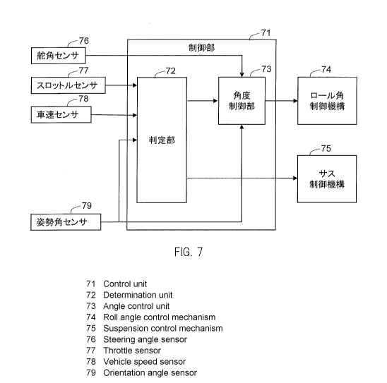
[FIG. 7] FIG. 7 is a block diagram illustrating an example configuration of a
control
system of the vehicle according to the embodiment.
[FIG. 8] FIG. 8 is a timing chart demonstrating an example of control of a
roll angle
and suspensions by the control section illustrated in FIG. 7.
[FIG. 9] FIG. 9 is a flowchart depicting an example process in which a
determination section determines start of roll angle control and suppression
of extension and
contraction of the suspensions.
[FIG. 10] FIG. 10 is a flowchart depicting an example process in which the
control
section updates a target value of the roll angle.
[FIG. 11] FIG. 11 is a flowchart depicting an example process in which the
determination section determines cancellation of the roll angle control and
the suppression of
extension and contraction of the suspensions.
[FIG. 12] FIG. 12 is a timing chart demonstrating another example of control
by the
control section.
[FIG. 13] FIG. 13 is a flowchart depicting an example process in which the
control
section performs roll angle control while the vehicle is stopped.
7
CA 03005803 2018-05-18
[FIG. 14] FIG. 14 is a view illustrating a variation of a linkage mechanism.
[FIG. 15] FIG. 15 is a view illustrating another variation of the linkage
mechanism.
[FIG. 16] FIG. 16 is a view illustrating still another variation of the
linkage
mechanism.
DESCRIPTION OF EMBODIMENT
[0021]
The inventors of the present teaching evaluated the control of a tilt (roll
angle) of a
vehicle at low speed by using an actuator. Specifically, in a case where the
body frame tilts
and the vehicle speed is below a threshold, the inventors operated the
actuator to set a body
frame in an upright position. The inventors intensively investigated a scene
where such roll
angle control is used.
[0022] The inventors focused on a control of a tilt angle of the body frame at
a start of
traveling. The inventors studied a control of maintaining the tilt angle of
the body frame in
the left direction or in the right direction near the upright position by
using the actuator until
the vehicle speed reached a threshold after the start of traveling. In this
case, after the start
of traveling, when the vehicle speed reaches or exceeds the threshold, the
control of the tilt
angle of the body frame in the left direction or in the right direction by
using the actuator is
canceled.
[0023] The inventors intensively studied a roll angle control by the actuator
and a
movement of a rider at start of traveling. Consequently, it was found that an
operation of the
rider immediately after the start varies depending on situations. For example,
control of a
vehicle posture by the rider after the start differs between a case where the
vehicle travels
straight after the start of traveling and a case where the vehicle turns
rightward or leftward
after the start.
[0024] In the tilt angle control discussed above, the body frame is maintained
near the
8
CA 03005803 2018-05-18
upright position by the actuator until the vehicle speed reaches the threshold
after the start of
traveling. After the vehicle speed has reached or exceeded the threshold, the
tilt angle of the
body frame is controlled mainly by an operation of the rider. At this time,
the rider controls
the vehicle posture depending on situations.
[0025] The inventors further concluded from the study that a rider's operation
not only at
start of traveling but also at stop of traveling before the start subtly
changes depending on
situations. The inventors found that a rider desires to tilt the vehicle
slightly from the
vertical direction at the start of traveling in some situations. Based on
these findings, the
inventors arrived at a configuration in which a tilt angle of the body frame
is controlled by
using an actuator based on a rider's operation while the vehicle is stopped.
This
configuration enables control of the tilt angle of the body frame while
closely reflecting a
rider's intention. Specifically, the inventors arrived at a configuration of a
vehicle according
to an embodiment described below.
[0026] A leaning vehicle according to the embodiment includes a body frame and
a right
wheel and a left wheel disposed in a left-right direction of the body frame.
The body frame
tilts rightward when turning rightward in a left-right direction of the
leaning vehicle, and tilts
leftward when turning leftward in the left-right direction of the leaning
vehicle. The leaning
vehicle includes a linkage mechanism. The linkage mechanism includes an arm
rotatably
supported on the body frame. The arm supports the right wheel and the left
wheel.
Relative positions of the right wheel and the left wheel relative to the body
frame in a top-
bottom direction of the leaning vehicle is changed by rotating the arm with
respect to the body
frame. Accordingly, the body frame tilts in the left direction of the leaning
vehicle or in the
right direction of the leaning vehicle. The leaning vehicle includes a left-
right tilt angle
control mechanism and a control section for controlling the left-right tilt
angle control
mechanism. The left-right tilt angle control mechanism includes an actuator
for adjusting a
9
CA 03005803 2018-05-18
rotation of the arm with respect to the body frame. The left-right tilt angle
control
mechanism controls a tilt angle of the body frame in the left direction of the
leaning vehicle or
in the right direction of the leaning vehicle. The control section controls
the left-right tilt
angle control mechanism to change the tilt angle of the body frame in
accordance with an
input to the leaning vehicle from the rider concerning a tilt of the body
frame in the left
direction of the leaning vehicle or in the right direction of the leaning
vehicle while the
leaning vehicle is stopped.
[0027] With this configuration, the control section changes the tilt
angle of the body frame
in the left direction or in the right direction in accordance with the input
to the leaning vehicle
from the rider while the vehicle is stopped. The control section uses
especially the input
from the rider concerning a tilt of the body frame in the left direction or in
the right direction
for control of the tilt angle. Accordingly, it is possible to control the tilt
angle of the body
frame in the left direction or in the right direction while the vehicle is
stopped, that is, before
the vehicle starts traveling, in accordance with a rider's operation of the
vehicle at the stop.
Consequently, the vehicle may start traveling in a posture suitable for an
operation intended
by a rider after the start. That is, a rider's intention for an operation
after the start is taken
into consideration from the input to the leaning vehicle from the rider at the
stop and is
reflected in the tilt angle of the body frame in the left direction or in the
right direction at the
start.
[0028] The inventors further studied a relationship between an input to the
leaning vehicle
from the rider at the stop and a rider's operation on the vehicle after the
start. As a result, the
inventors found that the rider tends to control a posture of the leaning
vehicle at the start by a
steering operation while the vehicle is stopped. Based on this finding, the
inventors arrived
at a configuration in which the control section controls the left-right tilt
angle control
mechanism to change the tilt angle of the body frame in the left direction or
in the right
CA 03005803 2018-05-18
direction in accordance with a steering angle of the handlebar at the stop of
the leaning
vehicle. This configuration enables control of the tilt angle of the body
frame in the left
direction or in the right direction in accordance with a rider's input of the
steering force to a
handlebar at the stop. Accordingly, the roll angle of the body frame at start
of traveling may
be adjusted to meet a rider's intention.
[0029] An embodiment of the present teaching will be described in detail with
reference to
the drawings.
[0030] In the drawings, arrow F represents the forward direction of a vehicle.
Arrow B
represents the rearward direction of the vehicle. Arrow U represents the
upward direction of
the vehicle. Arrow D represents the downward direction of the vehicle. Arrow R
represents the rightward direction of the vehicle. Arrow L represents the
leftward direction
of the vehicle.
[0031] The vehicle turns with the body frame being tilted in the left
direction of the vehicle
or in the right direction of the leaning vehicle relative to the vertical
direction. Thus, in
addition to the directions relative to the vehicle, directions relative to the
body frame are
defined. In the accompanying drawings, arrow FF represents the forward
direction of the
body frame. Arrow FB represents the rearward direction of the body frame.
Arrow FU
represents the upward direction of the body frame. Arrow FD represents the
downward
direction of the body frame. Arrow FR represents the rightward direction of
the body frame.
Arrow FL represents the leftward direction of the body frame.
[0032] The "front-rear direction of the body frame", the "left-right direction
of the body
frame", and the "top-bottom direction of the body frame" herein refer to the
front-rear
direction, the left-right direction, and the top-bottom direction,
respectively, relative to the
body frame when seen from a rider driving the vehicle. In addition, "to a side
of the body
frame" refers to the rightward or leftward direction of the body frame.
11
CA 03005803 2018-05-18
[0033] The expression "extending in the front-rear direction of the body
frame" herein
includes extending in a direction with a tilt relative to the front-rear
direction of the body
frame. In this case, a tilt of the extension direction relative to the front-
rear direction of the
body frame is often smaller than a tilt relative to the left-right direction
of the body frame and
a tilt relative to the top-bottom direction of the body frame.
[0034] The expression "extending in the left-right direction of the body
frame" herein
includes extending in a direction with a tilt relative to the left-right
direction of the body
frame. In this case, a tilt of the extension direction relative to the left-
right direction of the
body frame is often smaller than a tilt relative to the front-rear direction
of the body frame and
a tilt relative to the top-bottom direction of the body frame.
[0035] The expression "extending in the top-bottom direction of the body
frame" herein
includes extending in a direction with a tilt relative to the top-bottom
direction of the body
frame. In this case, a tilt of the extension direction relative to the top-
bottom direction of the
body frame is often smaller than a tilt relative to the front-rear direction
of the body frame and
a tilt relative to the left-right direction of the body frame.
[0036] The "upright position of the body frame" herein refers to a state where
the top-
bottom direction of the body frame coincides with the vertical direction. In
this state, the
directions relative to the vehicle coincide with the directions relative to
the body frame.
While the body frame is tilted in the left direction or in the right direction
relative to the
vertical direction, the left-right direction of the vehicle does not coincide
with the left-right
direction of the body frame. In this case, the top-bottom direction of the
vehicle does not
coincide with the top-bottom direction of the body frame, either. However,
even while the
body frame is tilted in the left direction or in the right direction relative
to the vertical
direction, the front-rear direction of the vehicle coincides with the front-
rear direction of the
body frame.
12
CA 03005803 2018-05-18
[0037] The expression "the roll angle of the body frame" herein refers to an
angle of
rotation of the body frame about the front-rear direction. The roll angle of
the body frame is
the same as a tilt angle of the body frame in the left direction of the
vehicle or in the right
direction of the vehicle. As an example, the roll angle may be expressed by an
angle of the
top-bottom direction of the body frame with respect to the vertical direction.
The vertical
direction is the same as the gravity direction.
[0038] (Vehicle Configuration)
FIG. 1 is a left side view of the entire vehicle 1 when viewed from the left.
The
vehicle 1 includes a vehicle body 2, a pair of left and right front wheels 3,
a rear wheel 4, a
linkage mechanism 5, and a steering mechanism 7.
[0039] The vehicle body 2 includes a body frame 21, a body cover 22, a sheet
24, and a
power unit 25. In FIG. 1, the body frame 21 is in an upright position. The
following
description with reference to FIG. 1 is based on a premise that the body frame
21 is in the
upright position. The vehicle 1 is a leaning vehicle. While the vehicle 1 is
turning, the
body frame 21 tilts in the turning direction.
[0040] The body frame 21 includes a head pipe 211, a down frame 212, and a
rear frame
213. In FIG. 1, a portion of the body frame 21 hidden by the body cover 22 is
indicated by
broken lines. The body frame 21 supports the sheet 24 and the power unit 25.
The power
unit 25 supports the rear wheel 4. The power unit 25 includes a driving source
such as an
engine, an electric motor, or a battery, and a device such as a transmission.
[0041] The head pipe 211 is disposed in a front portion of the vehicle 1. When
viewed
from a side of the body frame 21, an upper portion of the head pipe 211 is
disposed behind a
lower portion of the head pipe 211.
[0042] The down frame 212 is connected to the head pipe 211. The down frame
212 is
disposed behind the head pipe 211. The down frame 212 extends in the top-
bottom direction
13
CA 03005803 2018-05-18
of the body frame 21.
[0043] The rear frame 213 is disposed behind the down frame 212. The rear
frame 213
extends in the front-rear direction of the body frame 21. The rear frame 213
supports the
sheet 24 and the power unit 25.
[0044] The body cover 22 includes a front cover 221, a front spoiler 222, a
pair of left and
right front fenders 223, a rear fender 224, and a leg shield 225. The body
cover 22 is a body
part covering at least a portion of body parts mounted on the vehicle 1, such
as the pair of left
and right front wheels 3, the body frame 21, and the linkage mechanism 5.
[0045] FIG. 2 is a front view of a front portion of the vehicle 1 when viewed
from the front
of the body frame 21. In FIG. 2, the body frame 21 is in an upright position.
The
following description with reference to FIG. 2 is based on a premise that the
body frame 21 is
in the upright position. FIG. 2 illustrates a state where the front cover 221,
the front spoiler
222, and the pair of left and right front fenders 223 are detached.
[0046] The pair of front wheels 3 includes a right wheel 31 and a left wheel
32 arranged at
the right and left of the head pipe 211 (body frame 21). The linkage mechanism
5 and
suspensions (a right suspension 33 and a left suspension 35) are disposed
between the head
pipe 211 as a part of the body frame 21 and the pair of front wheels 3. That
is, the body
frame 21 is connected to the right wheel 31 and the left wheel 32 through the
linkage
mechanism 5 and the suspensions 33 and 35. The linkage mechanism 5 is disposed
below a
handlebar 23. The linkage mechanism 5 is disposed above the right wheel 31 and
the left
wheel 32.
[0047] In the example illustrated in FIG. 2, the linkage mechanism 5 is
connected to the
right wheel 31 and the left wheel 32 through the suspensions 33 and 35. The
arrangement of
the suspensions 33 and 35 is not limited to this example. For example, the
suspensions may
be disposed in a part of the linkage mechanism 5. Alternatively, the
suspensions may be
14
CA 03005803 2018-05-18
disposed between the linkage mechanism 5 and the body frame 21.
<Linkage Mechanism>
[0048] The linkage mechanism 5 of the vehicle 1 illustrated in FIG. 2 is a
linkage
mechanism of a parallel four-bar linkage (also called parallelogram linkage)
type linkage
mechanism. The linkage mechanism 5 includes an upper arm 51, a lower arm 52, a
right
side member 53, and a left side member 54.
[0049] The linkage mechanism 5 includes the upper arm 51 and the lower arm 52
(hereinafter collectively referred to as arms 51 and 52 when not specifically
distinguished)
rotatably supported on the body frame 21. The arms 51 and 52 are rotatable
about rotation
axes extending in the front-rear direction with respect to the body frame 21.
The rotation
axes are disposed at the centers of the arms 51 and 52 in the left-right
direction. That is,
intermediate portions of the arms 51 and 52 are supported by the head pipe 211
on support
parts A and D. The rotation axes of the arms 51 and 52 pass through the
support parts A and
D. The right wheel 31 is disposed at the right of the rotation axes, and
the left wheel 32 is
disposed at the left of the rotation axes. The right wheel 31 is connected to
right portions of
the arms 51 and 52 relative to the rotation axes through the right side member
53 and the right
suspension 33. The left wheel 32 is connected to left portions of the arms 51
and 52 relative
to the rotation axes through the left side member 54 and the left suspension
35.
[0050] As described above, since the right wheel 31 is connected to the right
portions of
the arms 51 and 52 relative to the rotation axes and the left wheel 32 is
connected to the left
portions of the arms 51 and 52 relative to the rotation axes, relative
positions of the right
wheel 31 and the left wheel 32 relative to the body frame 21 in the top-bottom
directions FU
and FD may be adjusted. That is, rotations of the arms 51 and 52 change
relative positions
the right wheel 31 and the left wheel 32 disposed at the right and left of the
rotation axes of
the arms 51 and 52 in the top-bottom directions FU and FD with respect to the
body frame 21.
CA 03005803 2018-05-18
When the relative positions of the right wheel 31 and the left wheel 32 in the
top-bottom
directions FU and FD change, the body frame 21 tilts in the left direction or
in the right
direction relative to the vertical direction. Accordingly, by adjusting the
rotations of the
arms 51 and 52 with respect to the body frame 21, a tilt in the left direction
or in the right
direction, that is, the roll angle, of the body frame 21 may be controlled.
[0051] The upper arm 51 includes a pair of plate-shaped members 512. The pair
of plate-
shaped members 512 is disposed ahead of and behind the head pipe 211. Each of
the plate-
shaped members 512 extends in the left-right direction of the body frame 21.
The lower arm
52 includes a pair of plate-shaped members 522. The pair of plate-shaped
members 522 is
disposed ahead of and behind the head pipe 211. Each of the plate-shaped
members 522
extends in the left-right direction of the body frame 21. The lower arm 52 is
disposed below
the upper arm 51. The length of the lower arm 52 in the left-right direction
of the body
frame 21 is equal to or approximately equal to the length of the upper arm 51
in the left-right
direction of the body frame 21. The lower arm 52 extends in parallel with the
upper arm 51.
[0052] The configurations of the arms 51 and 52 are not limited to the above
example.
For example, instead of the configuration in which the arms 51 and 52 are
constituted by the
pair of plate-shaped members, the arms 51 and 52 may be constituted by one
plate-like
member disposed ahead of the head pipe 211.
[0053] The right end of the upper arm 51 and the right end of the lower arm 52
are
connected to the right side member 53 extending in the top-bottom direction of
the body
frame 21. The right side member 53 is rotatably supported by the upper arm 51
and the
lower arm 52 on support parts B and E. The right side member 53 is rotatable
about rotation
axes passing through the support parts B and E in the front-rear direction
with respect to the
upper arm 51 and the lower arm 52.
[0054] The left end of the upper arm 51 and the left end of the lower arm 52
are connected
16
CA 03005803 2018-05-18
to the left side member 54 extending in the top-bottom direction of the body
frame 21. The
left side member 54 is rotatably supported by the upper arm 51 and the lower
arm 52 on
support parts C and F. The left side member 54 is rotatable about rotation
axes passing
through the support parts C and F in the front-rear direction with respect to
the upper arm 51
and the lower arm 52.
<Suspension>
[0055] The lower end of the right side member 53 is connected to the right
suspension 33
through a right bracket 317. The lower end of the left side member 54 is
connected to the
left suspension 35 through a left bracket 327. The right suspension 33 and the
left
suspension 35 may extend and contract in the top-bottom direction of the body
frame 21.
The upper end of the right suspension 33 is connected to the linkage mechanism
5, and the
lower end of the right suspension 33 is connected to the right wheel 31. The
upper end of
the left suspension 35 is connected to the linkage mechanism 5, and the lower
end of the left
suspension 35 is connected to the left wheel 32.
[0056] The suspensions 33 and 35 are telescopic suspensions, for example. The
suspensions may also be referred to as buffers. The right suspension 33
includes a right
outer cylinder 312 supporting the right wheel 31 and a right inner cylinder
316 disposed in an
upper portion of the right outer cylinder 312. The upper end of the right
inner cylinder 316
is fixed to the right bracket 317, and the lower end of the right inner
cylinder 316 is inserted
in the right outer cylinder 312. When the right inner cylinder 316 moves
relative to the right
outer cylinder 312, the right suspension 33 extends and contracts. The left
suspension 35
includes a left outer cylinder 322 supporting the left wheel 32 and a left
inner cylinder 326
disposed in an upper portion of the left outer cylinder 322. The upper end of
the left inner
cylinder 326 is fixed to the left bracket 327, and the lower end of the left
inner cylinder 326 is
inserted in the left outer cylinder 322. When the left inner cylinder 326
moves relative to the
17
CA 03005803 2018-05-18
left outer cylinder 322, the left suspension 35 extends and contracts.
[0057] A right rotation prevention mechanism 34 is connected between the right
bracket
317 and the right outer cylinder 312. The right rotation prevention mechanism
34 prevents
the right outer cylinder 312 from rotating about an axis extending in the
extension/contraction
direction of the right suspension 33 with respect to the right inner cylinder
316. A left
rotation prevention mechanism 36 is connected to between the left bracket 327
and the left
outer cylinder 322. The left rotation prevention mechanism 36 prevents the
left outer
cylinder 322 from rotating about an axis extending in the
extension/contraction direction of
the left suspension 35 with respect to the left inner cylinder 326.
[0058] Specifically, the right rotation prevention mechanism 34 includes a
right rotation
prevention rod 341, a right guide 313, and the right bracket 317. The right
guide 313 is
fixed to an upper portion of the right outer cylinder 312. The right guide 313
includes a
right guide cylinder 313b in a front portion thereof
[0059] The right rotation prevention rod 341 extends in parallel with the
right inner
cylinder 316. An upper portion of the right rotation prevention rod 341 is
fixed to a front
portion of the right bracket 317. The right rotation prevention rod 341 is
disposed ahead of
the right inner cylinder 316 with a part of the right rotation prevention rod
341 being inserted
in the right guide cylinder 313b. Accordingly, the right rotation prevention
rod 341 does not
move relative to the right inner cylinder 316. With relative movement of the
right inner
cylinder 316 relative to the right outer cylinder 312 in the direction in
which the right outer
cylinder 312 extends, the right rotation prevention rod 341 also moves
relative to the right
guide cylinder 313b. On the other hand, rotation of the right outer cylinder
312 about an
axis extending in the extension/contraction direction of the right suspension
33 with respect to
the right inner cylinder 316 is prevented.
[0060] The left rotation prevention mechanism 36 includes a left rotation
prevention rod
18
CA 03005803 2018-05-18
361, a left guide 323, and the left bracket 327. The left guide 323 is fixed
to an upper
portion of the left outer cylinder 322. The left guide 323 includes a left
guide cylinder 323b
in a front portion thereof
[0061] The left rotation prevention rod 361 extends in parallel with the
left inner cylinder
326. An upper portion of the left rotation prevention rod 361 is fixed to a
front portion of
the left bracket 327. The left rotation prevention rod 361 is disposed ahead
of the left inner
cylinder 326 with a part of the left rotation prevention rod 361 being
inserted in the left guide
cylinder 323b. Accordingly, the left rotation prevention rod 361 does not move
relative to
the left inner cylinder 326. With relative movement of the left inner cylinder
326 relative to
the left outer cylinder 322 in the direction in which the left outer cylinder
322 extends, the left
rotation prevention rod 361 also moves relative to the left guide cylinder
323b. On the other
hand, rotation of the left outer cylinder 322 about an axis extending in the
extension/contraction direction of the left suspension 35 with respect to the
left inner cylinder
326 is prevented.
[0062] The configuration of the suspensions is not limited to the above
example. For
example, the right suspension 33 may be configured in such a manner that two
combinations
of right outer cylinders 312 and inner cylinders 316 that move relative to
each other are
arranged side by side. In this case, similarly, the left suspension 35 may be
configured in
such a manner that two combinations of left outer cylinders 322 and left inner
cylinders 326
are arranged side by side. This configuration is a double telescopic
suspension. In this
case, the outer cylinder and the inner cylinder forming a pair of each of the
suspensions 33
and 35 are connected to each other not to move relative to each other so that
the suspensions
33 and 35 may also serve as rotation prevention mechanisms. In this case, the
right rotation
prevention mechanism 34 and the left rotation prevention mechanism 36 as
described above
are unnecessary.
19
CA 03005803 2018-05-18
[0063] <Roll Angle Control Mechanism>
The vehicle 1 includes a roll angle control mechanism 74 for controlling a
roll angle
of the body frame 21. FIG. 2 illustrates the roll angle control mechanism 74
by dotted lines.
The roll angle control mechanism 74 adjusts rotations of the arms 51 and 52
with respect to
the body frame 21. The adjustment of rotation of the arms 51 and 52 controls
the roll angle
of the body frame 21. The roll angle control mechanism 74 is connected to the
body frame
21 and to at least one of the arm 51 or the lower arm 52.
[0064] The adjustment of rotations of the arms 51 and 52 by the roll angle
control
mechanism 74 is not only for simply locking and unlocking the arms 51 and 52
but also for
controlling a rotary force. That is, the roll angle control mechanism 74 may
be configured to
adjust rotations of the arms 51 and 52 by generating a torque for rotating the
arms 51 and 52
with respect to the body frame 21 or a resistance to such a torque. For
example, the roll
angle control mechanism 74 may be configured to enable a change in the
magnitude of a force
for rotating the arms 51 and 52.
[0065] The roll angle control mechanism 74 may adjust rotations of the arms 51
and 52 so
that the roll angle of the body frame 21 reaches an arbitrarily set target
value. At this time,
the roll angle control mechanism 74 may monitor an actual roll angle of the
body frame 21 or
a torque to the arms 51 and 52, and by using a monitoring result, determine a
magnitude and
an orientation of a force for rotating the arms 51 and 52.
[0066] FIG. 3 is a left side view of a front portion of the vehicle 1 when
viewed from the
left of the body frame 21. In FIG. 3, the body frame 21 is in the upright
position. The
following description with reference to FIG. 3 is based on a premise that the
body frame 21 is
in the upright position. FIG. 3 illustrates a state where the front cover 221,
the front spoiler
222, and the pair of left and right front fenders 223 are detached. The left
side member 54
and a left transfer plate 63 are not shown in FIG. 3.
CA 03005803 2018-05-18
[0067] The roll angle control mechanism 74 includes an actuator 42 for
adjusting the
rotations of the arms 51 and 52 with respect to the body frame 21. The
actuator 42 is
connected to the head pipe 211 (body frame 21) through a support member 43.
The support
member 43 fixes the actuator 42 to the body frame 21. The actuator 42 includes
an output
member 461 that applies a rotary force to the upper arm 51 while being in
contact with the
upper arm 51. In the example illustrated in FIG. 3, the output member 461 is
an output shaft
that rotates about an axis. The output shaft of the output member 461 is
coaxial with the
rotation axis of the upper arm 51. Rotations of these output shafts are
transferred to the
rotation axis of the upper arm 51.
[0068] Although not shown, the actuator 42 may include a motor as a power
source and a
speed reducer that reduces the rotation speed of the motor and outputs the
reduced speed.
The speed reducer may be, for example, a deceleration gear that operates in
conjunction with
rotation of the motor. In this case, the output member 461 transfers rotations
of the motor
and the speed reducer to the outside.
[0069] The actuator 42 may operate based on a control signal from a control
section (not
shown) included in the vehicle 1. For example, the actuator 42 may adjust a
rotary force to
be applied to the arms 51 and 52 so that the roll angle of the body frame 21
reaches a target
value indicated by the control section. The actuator 42 may also control an
output based on
a signal from a sensor that detects a state of the vehicle 1. Examples of
sensors indicating
the state of the vehicle includes a posture sensor for detecting a posture of
the vehicle 1 and a
torque sensor for detecting a torque for rotations of the arms 51 and 52 with
respect to the
body frame. A process of determining an output of the actuator 42 based on
information
from the sensor may be executed by a control circuit or a control computer
incorporated in the
actuator 42 or may be executed by a control device external to the actuator
42.
[0070] The configuration of the actuator 42 is not limited to the above
example. For
21
CA 03005803 2018-05-18
example, the actuator 42 may be configured to be connected to at least one of
the upper arm
51 and the lower arm 52 and adjust rotation of the at least one of the upper
arm 51 and the
lower arm 52. For example, the output member of the actuator 42 may be an
axial shape
extending in a single-axis direction so that when the output member axially
contracts, the
output member applies a rotary force to the arms 51 and 52. In this case, the
actuator may
be configured in such a manner that one end of the actuator is rotatably
connected to the arms
51 and 52 and the other end of the actuator is rotatably connected to the body
frame 21. The
one end is connected to a portion away from the rotation axes of the arms 51
and 52.
Extension and contraction of the actuator in a direction connecting one end to
the other
enables the arms 51 and 52 to rotate with respect to the body frame 21. The
actuator 42 may
be a hydraulic actuator. That is, a power source of the actuator may be
electric or hydraulic.
The actuator 42 may be a damper device that applies a damping force to a
torque for rotating
the arms 51 and 52.
[0071] <Suspension Control Mechanism>
The vehicle 1 may include suspension control mechanisms that reduce extension
and contraction of the suspensions 33 and 35 (see FIG. 2). The suspension
control
mechanisms may be disposed inside the suspensions 33 and 35, for example. As
described
above, the suspensions 33 and 35 include inner cylinders 316 and 326 and outer
cylinders 312
and 322. With extension and contraction of the suspensions 33 and 35, a flow
of oil occurs
in the suspensions. In the suspensions 33 and 35, orifices that are oil
channels and
regulating valves for regulating flow rates in the oil channels are provided.
The suspension
control mechanisms may be configured to control the regulating valves.
Adjusting
mechanism for adjusting the regulating valves may be mechanical or electric.
In the case of
mechanical adjusting mechanisms, each of the mechanisms may be configured to
control the
position of the regulating valve by using a motor or a solenoid, for example.
In the case of
22
CA 03005803 2018-05-18
,
,
an electric adjusting mechanism, the regulating valves may be electromagnetic
regulating
valves. Each of the suspension control mechanisms may have a configuration
that adjusts a
magnetic fluid viscosity with a solenoid.
[0072] The suspension control mechanisms may control the regulating valves
based on a
signal from the control section of the vehicle 1. The suspension control
mechanisms control
opening and closing of the regulating valves to thereby regulate the flow
rates of oil in the
suspensions 33 and 35. The suspension control mechanisms may suppress
extension and
contraction of the suspensions 33 and 35 by reducing the flow rates. The
suspension control
mechanisms may cancel suppression of extension and contraction of the
suspensions 33 and
35 by increasing the flow rates. For example, when the regulating valves are
closed,
extension and contraction of the suspensions 33 and 35 are suppressed, whereas
when the
regulating valves are opened, suppression of extension and contraction of the
suspensions 33
and 35 are canceled (operations of extension and contraction are allowed).
[0073] The configuration of the suspension control mechanisms is not limited
to the above
example. For example, suspension control mechanisms may be provided to the
right
rotation prevention mechanism 34 and the left rotation prevention mechanism
36. For
example, in the configuration illustrated in FIG. 2, brake shoes may be
provided to guide
cylinders 313b and 323b in which the rotation prevention rods 341 and 361 are
inserted.
When the brake shoes are actuated, the brake shoes contact the rotation
prevention rods 341
and 361 and lock relative movements of the rotation prevention rods 341 and
361 relative to
the guide cylinders 313b and 323b. Each of the brake shoes may be actuated by
an actuator
such as a motor or a hydraulic actuator, for example. The actuator for the
brake shoes may
be attached to, for example, the body frame 21. The configuration of the
brakes used as the
suspension control mechanisms is not limited to the above example. For
example, the
brakes may have a configuration including a caliper or a configuration that
restricts extension
23
CA 03005803 2018-05-18
and contraction of the suspensions by breaking a parallel relationship between
the
extension/contraction direction of the rotation prevention mechanisms and the
extension/contraction direction of the suspensions.
[0074] The suspension control mechanism is provided independently of the
actuator 42 of
the roll angle control mechanism 74. In addition to the actuator 42, an
actuator for
suppressing extension and contraction of the suspensions 33 and 35 is
additionally provided.
In this manner, the power source of the suspension control mechanism may be
provided
independently of the power source of the roll angle control mechanism 74.
Accordingly,
extension and contraction of the suspensions 33 and 35 may be controlled
without constraint
of roll angle control. In addition, the roll angle control may be performed
independently of
control of the extension and contraction of the suspensions 33 and 35.
[0075] <Steering Mechanism 7>
As illustrated in FIG. 2, the steering mechanism 7 includes the handlebar 23
and the
steering force transfer mechanism 6. The steering force transfer mechanism 6
includes a
steering shaft 60 and a tie rod 67. In the example illustrated in FIG. 2, the
steering force
transfer mechanism 6 also includes the brackets 317 and 327 and the
suspensions 33 and 35.
The steering force transfer mechanism 6 is rotatably supported on the head
pipe 211 in a front
portion of the body frame 21, integrally with the handlebar 23. The steering
force transfer
mechanism 6 changes the directions of the right wheel 31 and the left wheel 32
in accordance
with rotation of the handlebar 23. That is, the steering force transfer
mechanism 6 transfers
a steering force input to the handlebar 23 with a rider's operation of the
handlebar 23, to the
right wheel 31 and the left wheel 32 through the right bracket 317 and the
left bracket 327.
[0076] The rotation axis Z of the steering shaft 60 extends in the top-bottom
direction of
the body frame 21. The handlebar 23 is attached to an upper portion of the
steering shaft 60.
The steering shaft 60 rotates about the rotation axis Z in accordance with an
operation of the
24
CA 03005803 2018-05-18
'
. ,
handlebar 23 by a rider. A part of the steering shaft 60 is rotatably
supported on the head
pipe 211. A lower portion of the steering shaft 60 is connected to the tie rod
67 extending in
the left-right direction through an intermediate transfer plate 61. The
intermediate transfer
plate 61 is relatively non-rotatable with respect to the steering shaft 60.
That is, the
intermediate transfer plate 61 is rotatable together with the steering shaft
60 about the
direction in which the steering shaft 60 extends.
[0077] The right end of the tie rod 67 is connected to the right bracket 317
through a right
transfer plate 62. The right transfer plate 62 is rotatable together with the
right side member
53 about the direction in which the right side member 53 extends.
[0078] The left end of the tie rod 67 is connected to the left bracket 327
through a left
transfer plate 63. The left transfer plate 63 is rotatable together with the
left side member 54
about the direction in which the left side member 54 extends.
[0079] FIG. 4 is a plan view of a front portion of the vehicle 1 when viewed
from above
the body frame 21. In FIG. 4, the body frame 21 is in the upright position.
The following
description with reference to FIG. 4 is based on a premise that the body frame
21 is in the
upright position. FIG. 4 illustrates a state where the front cover 221 is
detached. In FIG. 4,
the direction in which the right side member 53 extends is defined as a right
center axis X,
and the direction in which the left side member 54 is defined as a left center
axis Y. The
right center axis X and the left center axis Y extend in parallel with the
rotation axis Z of the
steering shaft 60.
[0080] As illustrated in FIG. 4, the intermediate transfer plate 61, the right
transfer plate
62, and the left transfer plate 63 are connected to the tie rod 67 through an
intermediate front
rod 641, a right front rod 651, and a left front rod 661, respectively. The
intermediate front
rod 641, the right front rod 651, and the left front rod 661 extend in the
front-rear direction of
the body frame 21, and are rotatable about the direction in which these rods
extend.
CA 03005803 2018-05-18
Accordingly, the intermediate front rod 641, the right front rod 651, and the
left front rod 661
are connected to the tie rod 67 to be rotatable about an axis extending in the
front-rear
direction.
[0081] The intermediate front rod 641, the right front rod 651, and the left
front rod 661 are
connected to the intermediate transfer plate 61, the right transfer plate 62,
and the left transfer
plate 63 through an intermediate joint 64, a right joint 65, and a left joint
66, respectively.
The intermediate front rod 641 is relatively rotatable about an axis parallel
to the rotation axis
Z with respect to the intermediate transfer plate 61. The right front rod 651
is relatively
rotatable about an axis parallel to the right center axis X with respect to
the right transfer plate
62. The left front rod 661 is relatively rotatable about an axis parallel to
the left center axis
Y with respect to the left transfer plate 63.
[0082] FIG. 5 is a plan view of a front portion of the vehicle 1 when viewed
from above
the body frame 21 in a state where the right wheel 31 and the left wheel 32
are steered
rightward.
[0083] When a rider operates the handlebar 23, the steering shaft 60 rotates
about the
rotation axis Z with respect to the head pipe 211. In the case of rightward
steering illustrated
in FIG. 5, the steering shaft 60 rotates in the direction of arrow G. With the
rotation of the
steering shaft 60, the intermediate transfer plate 61 rotates about the
rotation axis Z in the
direction of arrow G with respect to the head pipe 211.
[0084] With the rotation of the intermediate transfer plate 61 in the
direction of arrow G,
the intermediate front rod 641 of the tie rod 67 rotates about the
intermediate joint 64 in the
direction opposite to arrow G with respect to the intermediate transfer plate
61.
Accordingly, the tie rod 67 moves right-rearward while maintaining its
posture.
[0085] With the right-rearward movement of the tie rod 67, the right front rod
651 and the
left front rod 661 of the tie rod 67 rotate about the right joint 65 and the
left joint 66,
26
CA 03005803 2018-05-18
respectively, in the direction opposite to arrow G. Accordingly, the right
transfer plate 62
and the left transfer plate 63 rotate in the direction of arrow G while the
tie rod 67 maintains
its posture.
[0086]
With the rotation of the right transfer plate 62 in the direction of arrow G,
the right
bracket 317, which is relatively non-rotatable with respect to the right
transfer plate 62,
rotates about the right center axis X in the direction of arrow G with respect
to the right side
member 53.
[0087] When the left transfer plate 63 rotates in the direction of arrow G,
the left bracket
327, which is relatively non-rotatable with respect to the left transfer plate
63, rotates about
the left center axis Y in the direction of arrow G with respect to the left
side member 54.
[0088] When the right bracket 317 rotates in the direction of arrow G, the
right suspension
33, which is connected to the right bracket 317 through the right inner
cylinder 316, rotates
about the right center axis X in the direction of arrow G with respect to the
right side member
53.
Accordingly, the right wheel 31 supported by the right suspension 33 rotates
about the
right center axis X in the direction of arrow G with respect to the right side
member 53.
[0089] When the left bracket 327 rotates in the direction of arrow G, the left
suspension 35,
which is connected to the left bracket 327 through the left inner cylinder
326, rotates about
the left center axis Y in the direction of arrow G with respect to the left
side member 54.
Accordingly, the left wheel 32 supported by the left suspension 35 rotates
about the left center
axis Y in the direction of arrow G with respect to the left side member 54.
[0090] As described above, the steering force transfer mechanism 6 transfers a
steering
force to the right wheel 31 and the left wheel 32 in accordance with an
operation of the
handlebar 23 by the rider. The right wheel 31 and the left wheel 32 rotate
about the right
center axis X and the left center axis Y, respectively, in the directions in
accordance with the
operation direction of the handlebar 23 by the rider.
27
CA 03005803 2018-05-18
[0091] <Tilt Operation of Vehicle 1>
Next, with reference to FIGS. 2 and 6, a tilt operation of the vehicle 1 will
be
described. FIG. 6 is a front view of a front portion of the vehicle 1 in a
state where the body
frame 21 tilts leftward when viewed from the front of the body frame 21.
[0092] As illustrated in FIG. 2, in the upright position of the body frame 21,
the linkage
mechanism 5 forms a rectangle when the vehicle 1 is viewed from the front of
the body frame
21. As illustrated in FIG. 6, in the tilt state of the body frame 21, the
linkage mechanism 5
forms a parallelogram when the vehicle 1 is viewed from the front of the body
frame 21.
The deformation of the linkage mechanism 5 is in conjunction with the tilt of
the body frame
21 in the left direction or in the right direction. Actuation of the linkage
mechanism 5 means
that the upper arm 51, the lower arm 52, the right side member 53, and the
left side member
54 constituting the linkage mechanism 5 relatively rotate about the rotation
axes respectively
passing through the support parts A through F thereof so that the linkage
mechanism 5 is
thereby deformed.
[0093] For example, as illustrated in FIG. 6, when the rider tilts the vehicle
1 leftward, the
head pipe 211, that is, the body frame 21, tilts leftward relative to vertical
direction. When
the body frame 21 tilts, the upper arm 51 rotates about the axis passing
through the support
part A counterclockwise with respect to the body frame 21 when viewed from the
rider.
Similarly, the lower arm 52 rotates counterclockwise about the axis passing
through the
support part D. Accordingly, the upper arm 51 moves leftward relative to the
lower arm 52.
[0094] With the leftward movement of the upper arm 51, the upper arm 51
rotates about
the axis passing through the support part 13 and the axis passing through the
support part C
counterclockwise with respect to the right side member 53 and the left side
member 54,
respectively. Similarly, the lower arm 52 rotates about the axis passing
through the support
part E and the axis passing through the support part F counterclockwise with
respect to the
28
CA 03005803 2018-05-18
right side member 53 and the left side member 54, respectively. Accordingly,
the right side
member 53 and the left side member 54 tilt leftward relative to the vertical
direction while
maintaining a posture parallel to the body frame 21.
[0095] At this time, the lower arm 52 moves leftward relative to the tie rod
67. With the
leftward movement of the lower arm 52, the intermediate front rod 641, the
right front rod
651, and the left front rod 661 of the tie rod 67 rotate with respect to the
tie rod 67.
Accordingly, the tie rod 67 maintains a posture parallel to the upper arm 51
and the lower arm
52.
[0096] With the leftward tilt of the right side member 53, the right
wheel 31, which is
connected to the right side member 53 through the right bracket 317 and the
right suspension
33, tilts leftward while maintaining a posture parallel to the body frame 21.
[0097] With the leftward tilt of the left side member 54, the left wheel 32,
which is
connected to the left side member 54 through the left bracket 327 and the left
suspension 35,
tilts leftward while maintaining a posture parallel to the body frame 21.
[0098] The tilt operations of the right wheel 31 and the left wheel 32 have
been described
with respect to the vertical direction. In a tilt operation of the vehicle 1
(in actuation of the
linkage mechanism 5), the top-bottom direction of the body frame 21 does not
coincide with
the vertical direction. In the case where the description is given with
respect to the top-
bottom direction of the body frame 21, in actuation of the linkage mechanism
5, relative
positions of the right wheel 31 and the left wheel 32 relative to the body
frame 21 are
changed. In other words, the linkage mechanism 5 tilts the body frame 21
relative to the
vertical direction by changing the relative positions of the right wheel 31
and the left wheel 32
relative to the body frame 21 in the top-bottom direction of the body frame
21.
[0099] <System Configuration>
FIG. 7 is a block diagram illustrating an example configuration of a control
system
29
CA 03005803 2018-05-18
. ,
of the vehicle 1. In the example illustrated in FIG. 7, the control section 71
controls a roll
angle control mechanism 74 and a suspension control mechanism 75 based on
information
indicating a vehicle state. The control section 71 is connected to the roll
angle control
mechanism 74 and the suspension control mechanism 75 wirelessly or by wire.
For
example, the control section 71 is configured to enable transmission of a
control signal to a
driving unit of the roll angle control mechanism 74 and a driving unit of the
suspension
control mechanism 75. The driving unit of the roll angle control mechanism 74
may be, for
example, a driving unit or the like of the actuator 42 of the roll angle
control mechanism 74.
The driving unit of the suspension control mechanism 75 may be, for example,
an actuator, an
attenuating circuit, or another component of the suspension control mechanism
75.
[0100] The control section 71 is connected to a sensor for detecting a state
of the vehicle 1
wirelessly or by wire. The control section 71 receives information indicating
the state of the
vehicle 1 from the sensor. In the example illustrated in FIG. 7, a steering
angle sensor 76, a
throttle sensor 77, a vehicle speed sensor 78, and a posture angle sensor 79
are connected to
the control section 71.
[0101] <Sensor>
The steering angle sensor 76 sends, to the control section 71, a signal in
accordance
with the rotation angle and the rotation direction of the steering shaft 60.
The steering angle
sensor 76 is, for example, attached to the steering shaft 60 and detects
rotation of the steering
shaft 60 with respect to the body frame 21.
[0102] The throttle sensor 77 sends a signal in accordance with a throttle
opening degree of
the vehicle 1 to the control section 71. The throttle sensor 77 is attached to
the engine of the
vehicle 1, for example, and detects a throttle opening degree of a throttle
valve of the engine.
[0103] The vehicle speed sensor 78 sends a signal in accordance with a
traveling speed of
the vehicle 1 to the control section 71. The vehicle speed sensor 78 may
detect a rotation
CA 03005803 2018-05-18
'
speed of the wheel. In this case, the vehicle speed sensor 78 is attached to,
for example, an
axle of the front wheels 3 or the rear wheel 4 or an output shaft of a
transmission, and sends a
signal in accordance with the rotation speed of the wheel to the control
section 71.
[0104] The posture angle sensor 79 sends a signal in accordance with a roll
angle of the
body frame 21 to the control section 71. For example, the posture angle sensor
79 may be a
gyroscope for detecting a roll angular velocity and a roll angle of the body
frame 21. The
gyroscope may be a three-axis gyroscope for detecting angular velocities or
angles of a yaw
angle and a pitch angle in addition to the roll angle. The posture angle
sensor 79 is not
limited to a gyroscope. For example, the posture angle sensor 79 may be an
acceleration
sensor, a sensor for detecting rotation angles, angular velocities, or torques
of the arms 51 and
52 with respect to body frame 21, or a sensor for detecting an angle of a
pendulum hanging
from the body frame 21, a sensor for detecting a torque applied to the
actuator, or a current
detector of the actuator, or a combination of at least these two sensors.
[0105] Sensors connected to the control section 71 are not limited to the
above example.
For example, the control section 71 may receive information from an
acceleration sensor in
three-axis directions, an angular acceleration sensor for three axes, a
steering torque sensor,
an engine torque sensor, an engine revolution speed sensor, a seat pressure
sensor, or a stroke
sensor for detecting the operation amount of a brake, for example.
[0106] <Control Section>
The control section 71 includes a determination section 72 and an angle
control
section 73. The determination section 72 determines control of the roll angle
and control of
extension and contraction of the suspensions based on information acquired
from the group of
the sensors 77 through 79 and indicating the vehicle state. The angle control
section 73
controls the roll angle control mechanism based on the roll angle control
determined by the
determination section 72 and the roll angle of the body frame 21 detected by
the posture angle
31
CA 03005803 2018-05-18
sensor 79.
[0107] The determination section 72 determines whether roll angle control
during traveling
toward stop is necessary or not based on information acquired from at least
one of the group
of the sensors 77 through 79 and indicating the vehicle state. This
determination includes
determination of start or cancel of roll angle control during traveling toward
stop. For
example, the determination section 72 may determine whether roll angle control
during
traveling toward stop is necessary or not based on predetermined conditions
for the vehicle
state. If the vehicle state satisfies a first condition, for example, the
determination section 72
may determine to start roll angle control during traveling toward stop,
whereas if the vehicle
state satisfies a second condition, the determination section 72 may determine
to cancel the
roll angle control.
[0108] The state of "during traveling toward stop" is, for example, a
traveling state
determined to be highly probably stopped within several seconds. Determination
on whether
the vehicle is traveling toward stop or not is based on, for example, whether
the vehicle speed
is below a predetermined threshold or not. If the vehicle 1 shows a behavior
of traveling
toward stop, the determination section 72 determines to perform roll angle
control during
traveling toward stop. Accordingly, in a case where the vehicle increases the
speed again
from a decelerated state for stop, for example, the determination section 72
might determine
to perform roll angle control during traveling toward stop in some cases.
[0109] During traveling toward stop, the vehicle speed of the vehicle 1 is
in at least a part
of the low-speed traveling range. The low-speed traveling range refers to a
range in which
the vehicle speed of the vehicle 1 is lowest among a plurality of ranges
obtained by dividing
the entire vehicle-speed range except for a stopped state. That is, the entire
vehicle-speed
range of the vehicle 1 except for the stopped state may be divided into a high-
speed traveling
range and the low-speed traveling range. The low-speed traveling range may be
set as a
32
CA 03005803 2018-05-18
range where the vehicle speed v is higher than zero and is lower than an upper
limit VLu (i.e.,
0 <v < VLu). In this case, the high-speed traveling range is a range where the
vehicle speed
v is VLu or more and is a maximum speed Vmax of the vehicle 1 or less (i.e.,
VLu < v <
Vmax). The upper limit VLu of the low-speed traveling range is not limited to
a specific
value, and is set at a value depending on the type of the vehicle. The
threshold Th2 of the
vehicle speed for determining whether the vehicle is traveling toward stop or
not is a value of
the vehicle speed included in the low-speed traveling range.
[0110] The roll angle control during traveling toward stop may be, for
example, control of
causing the roll angle to approach a set target value. The target value is
determined by the
control section 71 based on an input to the vehicle from the rider. The
determination of the
target value may be performed by any one of the determination section 72 or
the angle control
section 73. For example, the control section 71 determines a target value in
accordance with
an input to the vehicle from the rider when the determination section 71
determines that the
vehicle state satisfies the first condition. In response to the determination
that the vehicle
state satisfies the first condition, the control section 71 detects an input
to the vehicle from the
rider. A point of time when it is determined that the vehicle state satisfies
the first condition
and a point of time when the input to the vehicle from the rider is detected
do not need to be
strictly the same.
[0111] The control section 7 may detect the input to the vehicle from the
rider from
information obtained by the group of the sensors 77 through 79 for detecting
the vehicle state.
For example, the control section 7 may use information acquired from the group
of the
sensors 77 through 79 as information indicating an input to the vehicle from
the rider or may
use the information acquired from the group of the sensors 77 through 79 for
determining an
input to the vehicle from the rider.
[0112] Examples of the information detected by vehicle-mounted sensors as an
input to the
33
CA 03005803 2018-05-18
vehicle from the rider include a vehicle speed, an acceleration, a throttle
opening degree, an
operating state of a brake, a roll angle of the body frame 21, a barycenter
shift of the vehicle,
a steering angle of the handlebar, motions of the body frame in three
directions (acceleration,
speed, and position), motions about three axes (acceleration, angular
velocity, angle), and a
pressure of a sheet. The control section 71 may also determine an input to the
vehicle from
the rider from a combination of information detected by a plurality of
sensors.
[0113] The input to the vehicle from the rider includes a case where the input
is zero.
That is, the control section 7 may determine roll angle control based on that
no input is made
from the rider to the vehicle for an event or that a value indicating an input
is zero for an
event. For example, in a case where the rider keeps the body frame 21 in the
upright
position during traveling, the detected roll angle is zero degrees, and a
change in the roll angle
over time is also zero. In such a case, the information that the roll angle or
a change in the
roll angle is zero may be used for determining an operation of the control
section 7.
[0114] In this embodiment, description will be given on a case where the
control section 71
detects the roll angle of the body frame 21 as an input to the vehicle from a
rider, as an
example. If the control section 71 determines that the state of the vehicle 1
satisfies the first
condition, the control section 71 acquires a roll angle of the body frame 21
from the posture
angle sensor 79. Accordingly, the roll angle of the body frame 21 in the case
where the state
of the vehicle 1 satisfies the first condition may be acquired. The control
section 71 sets the
acquired roll angle as a target value. The angle control section 73 controls
the roll angle
control mechanism 74 to cause the roll angle of the body frame 21 to reach the
set target
value. Accordingly, the roll angle of the body frame 21 obtained when the
state of the
vehicle 1 is determined to satisfy the first condition, that is, when the
vehicle becomes a
traveling state toward stop, is maintained. This roll angle may be maintained
at and after the
stop of the vehicle 1. Accordingly, traveling toward stop and stop of the
vehicle may be
34
CA 03005803 2018-05-18
performed in a vehicle posture in accordance with a rider's intention.
[0115] The control section 71 may update the target value of the roll angle in
accordance
with an input to the vehicle 1 from the rider after the determination that the
state of the
vehicle 1 satisfies the first condition, that is, in a period in which the
roll angle control during
traveling toward stop is performed. For example, in the period in which roll
angle control
during traveling toward stop is performed, the target value may be updated in
accordance with
an actual roll angle of the body frame 21.
[0116] Specifically, the control section 71 may control the roll angle
control mechanism in
accordance with an operation of the rider during traveling toward stop to
cause the roll angle
of the body frame 21 to approach zero degrees with respect to the vertical
direction. That is,
in a case where the rider performs an operation of causing the roll angle of
the body frame to
approach zero degrees with respect to the vertical direction in the period in
which roll angle
control during traveling toward stop is performed, the control section 71 may
control the roll
angle control mechanism in accordance with the operation of the rider to cause
the roll angle
of the body frame 21 to approach zero degrees with respect to the vertical
direction. At this
time, when the roll angle of the body frame 21 changes to approach zero
degrees from the
target value with respect to the vertical direction, the control section 71
sets the roll angle
after the change as a target value. Accordingly, control may be performed in
such a manner
that during traveling toward stop and after the stop, a rider's operation of
tilting the vehicle in
a direction in which the roll angle of the body frame approaches zero degrees
is permitted, but
a rider's operation of tilting the vehicle in the opposite direction is not
permitted.
[0117] The expression that "the roll angle of the body frame approaches zero
degrees with
respect to the vertical direction" means that, when supposing the roll angle
of the body frame
in a case where the top-bottom direction of the body frame coincides with the
vertical
direction to be zero degrees, the roll angle changes to approach zero degrees.
CA 03005803 2018-05-18
[0118] The determination section 72 determines whether extension and
contraction of the
suspensions 33 and 35 are necessary or not based on information indicating the
vehicle state
and acquired from at least one of the group of the sensors 77 through 79. This
necessity
determination includes determination on start or cancel of suppression of
extension and
contraction of the suspensions 33 and 35. For example, it may be determined
whether
suppression of extension and contraction of the suspensions 33 and 35 based on
predetermined conditions of the vehicle state. If the vehicle state satisfies
a third condition,
for example, the determination section 72 determines to start suppression of
extension and
contraction of the suspensions 33 and 35, whereas if the vehicle state
satisfies a fourth
condition, the determination section 72 determines to cancel suppression of
extension and
contraction of the suspensions 33 and 35.
[0119] The suppression of extension and contraction of the suspensions 33 and
35 may be a
mode of locking to prevent extension and contraction of the suspensions 33 and
35, for
example. Alternatively, the suppression of extension and contraction of the
suspensions 33
and 35 may be a mode of applying a resistance against a force of extension and
contraction of
the suspensions 33 and 35 or a mode of increasing such a resistance.
[0120] In at least a part of the roll angle control period during traveling
toward stop, the
determination section 72 may determine to reduce extension and contraction of
the
suspensions 33 and 35. That is, the first through fourth conditions may be set
in such a
manner that extension and contraction of the suspensions 33 and 35 are
suppressed in at least
a part of a period in which the roll angle control during traveling toward
stop is performed.
For example, by making the first condition and the third conditions the same,
the
determination section 72 may determine to start roll angle control during
traveling toward
stop and suppression of extension and contraction of the suspensions 33 and 35
at the same
time. Alternatively, by making the first condition and the third condition
different from each
36
CA 03005803 2018-05-18
other, the determination section 72 may start suppression of extension and
contraction of the
suspensions 33 and 35 and start roll angle control during traveling toward
stop at different
times. Alternatively, the determination section 72 may include start of roll
angle control
during traveling toward stop in a condition for start of suppression of
extension and
contraction of the suspensions.
[0121] The determination section 72 may perform determination in such a manner
that the
roll angle control during traveling toward stop continues after stop of the
vehicle. For
example, the second condition may be set not to cancel the roll angle control
during traveling
toward stop even when the vehicle 1 stops. For example, a condition in which
the vehicle
speed exceeds a predetermined threshold may be included in the second
condition. In this
case, if the vehicle 1 stops and then starts traveling so that the vehicle
speed exceeds the
threshold, the determination section 72 may determine to cancel roll angle
control during
traveling toward stop.
[0122] The determination section 72 may still continue suppression of
extension and
contraction of the suspensions after stop of the vehicle. For example, the
fourth condition
may be set in such a manner that suppression of extension and contraction of
the suspensions
is not canceled even when the vehicle 1 stops. For example, a condition in
which the vehicle
speed exceeds a predetermined threshold may be included in the fourth
condition. In this
case, if the vehicle 1 stops and then starts traveling so that the vehicle
speed exceeds the
threshold, the determination section 72 may determine to cancel suppression of
extension and
contraction of the suspensions.
[0123] The determination section 72 may determine whether roll angle control
during
traveling toward stop is necessary or not and whether suppression of extension
and
contraction of the suspensions is necessary or not, by using a plurality of
parameters
indicating a vehicle state. The plurality of parameters indicating the vehicle
state are
37
CA 03005803 2018-05-18
determined based on information obtained from the sensors 77 through 79. The
determination section 72 compares the parameters indicating the vehicle state
with thresholds
to thereby perform the determinations described above. These thresholds are
data indicating
the first through fourth conditions. The thresholds may be recorded in a
storage unit (e.g.,
memory) of the control section 71 beforehand. That is, the control section 71
may store data
indicating the first through fourth conditions beforehand. The determination
section 72 may
change the thresholds depending on the vehicle state.
[0124] A combination of parameters used for determining whether roll angle
control during
traveling toward stop is necessary or not may be different from a combination
of parameters
used for determining whether suppression of extension and contraction of the
suspensions is
necessary or not. At least one parameter used for determining whether roll
angle control
during traveling toward stop is necessary or not may be the same as a
parameter used for
determining whether suppression of extension and contraction of the
suspensions is necessary
or not. In this case, a threshold of the parameter used for determining
whether roll angle
control during traveling toward stop is necessary or not may be different from
a threshold of
the parameter used for determining whether suppression of extension and
contraction of the
suspensions is necessary or not.
[0125] As an example, a combination of parameters used for determining start
of roll angle
control during traveling toward stop may be constituted by the vehicle speed,
the throttle
opening degree, and the roll angle, and a combination of parameters used for
determining start
of suppression of extension and contraction of the suspensions may be
constituted by only the
vehicle speed. In this example, a threshold of the vehicle speed used for
determining start of
roll angle control during traveling toward stop may be different from a
threshold of the
vehicle speed used for determining start of suppression of extension and
contraction of the
suspensions.
38
CA 03005803 2018-05-18
[0126] If the determination section 72 determines that roll angle control
during traveling
toward stop is performed, the angle control section 73 determines control of
rotations of the
arms 51 and 52 based on the roll angle of the body frame 21 detected by the
posture angle
sensor 79. The angle control section 73 determines the magnitude and direction
of a rotary
force as control of rotation, and outputs the magnitude and direction to the
roll angle control
mechanism 74. For example, the angle control section 73 may determine the
magnitude and
direction of the rotary force applied to the arms 51 and 52 based on a target
value of the roll
angle and the roll angle detected by the posture angle sensor 79. Accordingly,
an actual roll
angle of the body frame 21 may be fed back to control by the roll angle
control mechanism.
[0127] For example, the angle control section 73 may determine the rotation
direction of
the arms 51 and 52 that reduces the difference between the target value of the
roll angle and
the roll angle detected by the posture angle sensor 79, as the direction of a
rotation to be
applied. The angle control section 73 may determine a magnitude of the rotary
force to be
applied in accordance with the difference between the target value of the roll
angle and the
roll angle detected by the posture angle sensor 79. The angle control section
73 may also
determine the magnitude of a rotary force to be applied based on a torque to
rotation of the
arms 51 and 52 with respect to the body frame 21.
[0128] The control of the angle control section 73 is not limited to the
control of reducing
the difference between the roll angle detected by the posture angle sensor 79
and the target
value of the roll angle. The angle control section 73 may determine, for
example, an
instruction value of a motor of an actuator by using a rotation speed or a
torque of the arms
with respect to the body frame and a current value of the motor.
[0129] <Roll Angle Control during Stop>
The determination section 72 determines whether the vehicle 1 is stopped or
not.
For example, in a case where the vehicle speed detected by the vehicle speed
sensor 78 is
39
CA 03005803 2018-05-18
. .
zero, the determination section 72 may determine that the vehicle 1 is
stopped. If the
determination section 72 determines that the vehicle 1 is stopped, the control
section 71
determines a target value of the roll angle during stop in accordance with an
input to the
vehicle 1 during stop from a rider. Based on the determined target value of
the roll angle
during stop and the roll angle detected by the posture angle sensor 79, the
angle control
section 73 determines control of rotation of the arms 51 and 52. The angle
control section
73 determines the magnitude and direction of a rotary force as control of
rotation, and outputs
the magnitude and direction to the roll angle control mechanism 74. The roll
angle control
mechanism 74 applies a rotary force to the arms 51 and 52 in accordance with
an output from
the angle control section 73. Accordingly, the roll angle of the body frame 21
is controlled
in accordance with the input to the vehicle from the rider during stop.
[0130] For example, if it is determined that the vehicle state satisfies a
predetermined
condition (fifth condition) while the vehicle 1 is stopped, the control
section 71 may control
the roll angle control mechanism so as to change the roll angle of the body
frame 21 in
accordance with the input to the vehicle 1 from the rider. In this case, the
fifth condition
may include another condition in addition to the stopped state of the vehicle
1. As another
condition, a state of traveling start preparation of the vehicle 1 may be
included, for example.
Accordingly, if the state of the vehicle 1 satisfies the fifth condition, for
example, the
determination section 72 may determine that the vehicle is stopped with a high
possibility of
start of traveling. That is, if the determination section 72 determines that
the vehicle is
stopped with a high possibility of start of traveling based on the fifth
condition, the control
section 71 may cause the roll angle control mechanism 74 to control the roll
angle during stop
in accordance with the input to the vehicle from the rider during stop.
[0131] The fifth condition is not limited to a specific condition, but
may be a vehicle state
serving as a basis of determination on whether to perform roll angle control
during stop or
CA 03005803 2018-05-18
not. For example, the fifth condition may include a condition that the engine
is running and
the rider is seated on the sheet 24.
[0132] The input to the vehicle 1 from the rider during stop may be detected
based on
information obtained by the group of the sensors 77 through 79 for detecting
vehicle states, in
a manner similar to that described above. In this embodiment, description is
given on a case
where an input to the handlebar during stop is detected as an input to the
vehicle 1 from the
rider, as an example. If the determination section 72 determines that the
vehicle state
satisfies the fifth condition (i.e., if the determination section 72
determines to perform roll
angle control in accordance with the rider's input during stop), the control
section 71 acquires
a steering angle of the handlebar detected by the steering angle sensor 76.
The steering
angle of the handlebar is not necessarily acquired from the steering angle
sensor 76. For
example, a torque of the steering shaft 60 detected by a torque sensor of the
steering shaft 60
(an example of a steering torque) may be acquired as an input to the
handlebar.
[0133] The control section 71 determines a target value of the roll angle in
accordance with
at least one of a direction or a degree of the steering angle of the handlebar
acquired from the
steering angle sensor 76. The angle control section 73 controls the roll angle
control
mechanism 74 so as to cause the roll angle to reach the determined target
value.
[0134] For example, in a case where the input to the handlebar is in a
direction of turning
rightward, the control section 71 may set a target value of the roll angle so
as to tilt the
vehicle 1 rightward, whereas in a case where the input to the handlebar is in
a direction of
turning leftward, the control section 71 may set a target value of the roll
angle so as to tilt the
vehicle 1 leftward. The control section 71 may set a target value in such a
manner that the
roll angle of the vehicle 1 has a degree in accordance with a degree of the
steering angle of the
handlebar.
[0135] The control section 71 may be constituted by an electronic control unit
(ECU).
41
CA 03005803 2018-05-18
The control section 71 may be constituted by a computer including a processor
and a memory
or a circuit formed on a board. In the case where the control section 71 is
constituted by a
computer, the process of the control section 71 is, for example, implemented
by reading and
executing a program from a memory with the processor. Such a program and a non-
transitory recording medium in which the program is recorded are also included
in the
embodiment of the present teaching.
[0136] The configuration of the control section 71 is not limited to the
example illustrated
in FIG. 7. For example, the control section 71 may not have the function of
controlling the
suspension control mechanism 75. The control section 71 may not have the
function of
controlling the roll angle during traveling toward stop. For example, the
determination
section 72 and the angle control section 73 may be constituted by computers
independently
of each other or circuits formed on different boards. For example, the angle
control section
73 may be incorporated in a part of the roll angle control mechanism 74.
[0137] <Operation Example>
FIG. 8 is a timing chart demonstrating an example of control of a roll angle
and a
suspension by the control section 71 illustrated in FIG. 7. In FIG. 8, the
abscissa represents
time. The ordinate represents the vehicle speed or the roll angle. The line V1
represents a
change in the vehicle speed over time, and line R1 represents a change in a
roll angle over
time. The threshold Th 1 represents a threshold of the vehicle speed for use
in determining
start of suppression of extension and contraction of the suspensions (an
example of the third
condition). The threshold Th2 represents a threshold of the vehicle speed for
use in
determining whether to start roll angle control during traveling toward stop
(an example of the
first condition). The threshold Th3 represents a threshold of a vehicle speed
for use in
determining whether to cancel suppression of extension and contraction of the
suspensions
(an example of the fourth condition). The threshold Th4 represents a threshold
of the
42
CA 03005803 2018-05-18
vehicle speed for use in determining whether to cancel roll angle control
during traveling
toward stop (an example of the second condition).
[0138] In the example shown in FIG. 8, when the vehicle speed decreases below
the
threshold Th 1 at time ti, the determination section 72 determines start of
suppression of
extension and contraction of the suspensions. At time ti, the control section
71 issues an
instruction of suppressing extension and contraction of the suspensions to the
suspension
control mechanism 75. The suspension control mechanism 75 locks the
suspensions to
prevent the suspensions from extending and contracting.
[0139] At time t2, when the vehicle speed decreases below the threshold Th2,
the
determination section 72 determines to start roll angle control during
traveling toward stop.
Although not shown, it is assumed that at time t2, the throttle opening degree
and the roll
angle have already satisfied the condition for starting roll angle control
during traveling
toward stop (first condition). At time t2, the control section 71 instructs
the roll angle
control mechanism 74 to control the roll angle during traveling toward stop.
In this
example, since Thl > Th2, after the start of suppression of extension and
contraction of the
suspensions, roll angle control during traveling toward stop starts.
[0140] The determination section 72 sets a roll angle R(t2) at time t2 as a
target value of
the roll angle during traveling toward stop. The angle control section 73
compares the roll
angle R(t2) with a roll angle Rs detected by the posture angle sensor 79. If
the signs
(positive (+) or negative (¨)) of R(t2) and Rs are the same and IR(t2)I <
IRsj, the angle control
section 73 determines a rotary force of the arms 51 and 52 in such a manner
that Rs = R(t2) is
established. Here, as an example, a roll angle in a state where the top-bottom
direction of
the body frame 21 coincides with the vertical direction (gravity direction) is
defined as zero
degrees. A roll angle in a state where the body frame 21 tilts rightward with
respect to the
vertical direction is defined as positive (+), and a roll angle in a state
where the body frame 21
43
CA 03005803 2018-05-18
tilts leftward with respect to the vertical direction is defined as negative
(¨). In this manner,
at and after time t2, the roll angle is kept at R(t2).
[0141] In
this example, since the threshold Th3 > 0, if the vehicle speed is zero, it is
determined that the condition for starting roll angle control during traveling
toward stop (first
condition) is satisfied and the condition for canceling the roll angle control
(second condition)
is not satisfied. Similarly, since the threshold Th4 > 0, if the vehicle speed
is zero, it is
determined that the condition for starting suspension suppression control
(third condition) is
satisfied and the condition for canceling the suspension suppression control
(fourth condition)
is not satisfied. Thus, after the vehicle 1 stops at time t3, roll angle
control and suppression
of extension and contraction of the suspensions during traveling toward stop
still continue.
[0142] FIG. 9 is a flowchart depicting an example process in which the
determination
section 72 determines whether to start roll angle control and suppression of
extension and
contraction of the suspensions during traveling toward stop. The determination
section 72
determines whether or not the vehicle speed is a threshold or less (Si). If
the vehicle speed
is the threshold or less, the determination section 72 determines to start
suppression of
extension and contraction of the suspensions (S2). The determination section
72 determines
whether or not each of the throttle opening degree, the vehicle speed, and the
roll angle is
within a threshold, inclusive (S3 through S5). If each of the throttle opening
degree, the
vehicle speed, and the roll angle is within the threshold, inclusive, the
determination section
72 determines start of roll angle control during traveling toward stop (S6).
The
determination section 72 records a roll angle (R(t2) in the example of FIG. 8)
when start of
the roll angle control is determined in the memory as a target value. The
angle control
section 73 issues an instruction to the roll angle control mechanism 74 so as
to hold the roll
angle of the body frame 21 at the target value (S7). The process in FIG. 9 may
be executed
by the determination section 72 in predetermined cycles.
44
CA 03005803 2018-05-18
[0143] With reference to FIG. 8 again, suppose at time t4, a rider performs an
operation of
causing a tilt of the vehicle 1 in the left direction or in the right
direction to approach zero
degrees with respect to the vertical direction (gravity direction). In this
case, the control
section 71 controls the roll angle control mechanism 74 in such a manner that
the roll angle of
the body frame 21 approaches zero degrees in accordance with the operation of
the rider.
Accordingly, the roll angle changes to approach zero degrees by an amount in
accordance
with the rider's operation (time t5). The control section 71 sets a roll angle
after the change
in accordance with the rider's operation as a new target value. Accordingly,
in the roll angle
control during traveling toward stop, the roll angle control mechanism may
control the roll
angle so as to permit motion of causing the tilt of the vehicle 1 to approach
the upright
position by a rider's operation.
[0144] FIG. 10 is a flowchart depicting a process in which the control section
71 updates a
target value of the roll angle. The control section 71 (the determination
section 72 or the
angle control section 73) determines whether the roll angle Rs of the body
frame 21 acquired
from the posture angle sensor 79 is closer to the zero degrees than the set
target value (R(t2)
in the example of FIG. 8) or not (S11). For example, the control section 71
determines
whether 1R(t2)1 > iRsi or not. If YES in Si!, the control section 71 updates
the target value
to the roll angle Rs acquired from the posture angle sensor 79 (S12). The
angle control
section 73 issues an instruction to the roll angle control mechanism 74 so
that the roll angle of
the body frame 21 is held at the updated target value (S13). The control
section 71 may
repeatedly perform the process of FIG. 10 at predetermined intervals in a
period in which roll
angle control during traveling toward stop is performed.
[0145] In the example illustrated in FIG. 10, the control section 21
compares the current
roll angle of the body frame 21 acquired from the posture angle sensor 79 with
the target
value, and if the current roll angle is closer to zero degrees (where the
vertical direction is
CA 03005803 2018-05-18
defined as zero degrees) than the target value, updates the target value
recorded on the
memory to the value of the current roll angle. The angle control section 73
controls the roll
angle control mechanism 74 in such a manner that the body frame 21 holds the
target value.
With this control, if the roll angle of the body frame 21 changes to a
direction away from zero
degrees relative to the target value, the roll angle control mechanism 74
applies a rotary force
to the arms 51 and 52 in order to return the roll angle to the target value.
On the other hand,
if the roll angle of the body frame 21 changes to approach zero degrees with
respect to the
vertical direction, the roll angle control mechanism 74 applies a rotary force
to the arms 51
and 52 in order to maintain the roll angle after the change.
[0146] With the process shown in FIG. 10, in a case where the rider stops the
vehicle on a
road tilted in the left direction or in the right direction, for example, the
rider may perform an
operation of stopping the vehicle with a slight tilt toward a peak portion of
the road surface
and, after the stop, returning the body frame to the vertical direction.
Accordingly, in
stopping the vehicle 1 on a tilt, the rider may perform an operation of
tilting the body frame
slightly to the peak portion of the road surface and then returning the body
frame to the
upright position. As a result, it is possible to perform roll angle control
following a rider's
intention that changes depending on situations.
[0147] With reference to FIG. 8 again, the vehicle 1 starts traveling at
time t6. After the
start of traveling of the vehicle 1, when the vehicle speed exceeds the
threshold Th4 at time
t7, the determination section 72 determines to cancel roll angle control
during traveling
toward stop. At time t7, the control section 71 instructs cancellation of roll
angle control
during traveling toward stop to the roll angle control mechanism 74.
[0148] When the vehicle speed exceeds the threshold Th3 at time t8, the
determination
section 72 determines cancellation of suspension suppression control. At time
t8, since Th3
> Th4 in this example, after cancellation of roll angle control during
traveling toward stop,
46
CA 03005803 2018-05-18
suppression of extension and contraction of the suspensions is canceled.
[0149] FIG. 11 is a flowchart depicting an example process in which the
determination
section 72 determines to cancel roll angle control and suppression of
extension and
contraction of the suspensions during traveling toward stop. The determination
section 72
determines whether or not at least one of the throttle opening degree, the
vehicle speed, or the
acceleration is at or above a threshold (S21 through S23). For example, if the
vehicle speed
exceeds a threshold (Th3 in the example of FIG. 8), the determination section
72 determines
to cancel roll angle control during traveling toward stop (S24). The
determination section 72
determines whether or not the vehicle speed is a threshold (Th4 in the example
of FIG. 8) or
less (S25). If the vehicle speed is at or above the threshold, the
determination section 72
determines to cancel suppression of extension and contraction of the
suspensions (S26). In
the example of FIG. 11, if it is determined that the condition for canceling
roll angle control
during traveling toward stop is satisfied, determination of canceling
suppression of extension
and contraction of the suspensions is executed. Thus, after cancellation of
roll angle control
during traveling toward stop, cancellation of suppression of extension and
contraction of the
suspensions is executed.
[0150] In the operation example of FIG. 8, extension and contraction of the
suspensions are
suppressed in a period in which roll angle control during traveling toward
stop is performed
(t2 through t7). Accordingly, in the period in which roll angle control during
traveling
toward stop is performed, responsiveness of the roll angle of the body frame
to adjustment of
rotations of the arms 51 and 52 by the roll angle control mechanism 74 is
high. Thus, in
traveling toward stop, movement of the roll angle of the body frame 21
controlled by the roll
angle control mechanism 74 may be easily converged. As a result, the roll
angle may be
controlled depending on various possible situations occurring during traveling
toward stop.
[0151] In addition, even in a case where extension and contraction of the
suspensions 33
47
CA 03005803 2018-05-18
and 35 is suppressed while the vehicle 1 is traveling toward stop, the linkage
mechanism 5 of
the vehicle 1 absorbs movement of the right wheel 31 and the left wheel 32 in
the top-bottom
direction with respect to the body frame 21. Accordingly, an increase in
vibrations of the
body frame caused by suppression of extension and contraction of the
suspensions 33 and 35
during traveling toward stop may be reduced.
[0152] In the example of FIG. 8, extension and contraction of the suspensions
are
suppressed in the entire period in which roll angle control during traveling
toward stop is
performed (t2 through t7). Alternatively, extension and contraction of the
suspension may
be suppressed in a part of this period. In this case, convergence of the roll
angle may be
improved, advantageously.
[0153] FIG. 12 is a timing chart demonstrating another example of control of
the roll angle
and the suspensions by the control section 71. In the example demonstrated in
FIG. 12, the
roll angle is controlled in accordance with the steering angle of the
handlebar in a period in
which the vehicle is stopped (time t3 through t6). That is, the determination
section 72
determines to perform roll angle control in accordance with an input from a
rider to the
vehicle 1 during stop in the period from time t3 through t6 in which the
vehicle speed is zero.
In a case where the vehicle state satisfies another condition in addition to
the condition that
the vehicle speed is zero, the determination section 72 may also determine to
perform roll
angle control in accordance with the input from the rider to the vehicle 1
during stop.
[0154] At time t51 in the period from time t3 through t6 in which the vehicle
1 is stopped,
the control section 71 detects a change in the steering angle of the handlebar
as an input to the
vehicle from the rider. At time t51, the control section 71 updates the target
value of the roll
angle to a roll angle in accordance with the steering angle of the handlebar.
The control
section 71 performs control of causing the roll angle control mechanism 74 to
operate so that
the roll angle of the body frame 21 reaches the updated target value.
Accordingly, at time
48
CA 03005803 2018-05-18
t52, the roll angle of the body frame 21 reaches the target value.
[0155] From time t52 to time t6 at which the vehicle 1 starts traveling,
the roll angle of the
body frame 21 is maintained at the target value. Since the vehicle speed is
not zero after
time t6, the determination section 21 finishes roll angle control in
accordance with the input
from the rider to the vehicle 1 during stop. After time t6, the control
section 71 does not
update the target value of the roll angle even with a change in the steering
angle of the
handlebar.
[0156] After start of traveling of the vehicle 1, at time t7, when the
vehicle speed exceeds
the threshold Th4 and the second condition is satisfied, the determination
section 72
determines cancellation of the roll angle control toward stop. After time t7,
the roll angle of
the body frame 21 changes in accordance with a rider's operation.
[0157] FIG. 13 is a flowchart depicting an example process in which the
control section 71
performs roll angle control during stop of the vehicle 1. In the example
depicted in FIG. 13,
the control section 71 determines a roll angle in accordance with the steering
angle detected
by the steering angle sensor 76 (S31). The angle control section 73 updates
the target value
of the roll angle recorded in a memory to the value determined at step S31
(S32). The angle
control section 73 issues an instruction to the roll angle control mechanism
74 so as to hold
the roll angle of the body frame 21 at the updated target value (S33). The
control section 71
may perform the process depicted in FIG. 13 in a case where a change in the
steering angle of
the handlebar is detected, for example.
[0158] Through the process depicted in FIG. 13, the roll angle during stop may
be changed
in accordance with the steering angle. Accordingly, the body frame 21 may be
tilted in
accordance with a change in the steering angle before start of traveling.
Consequently, the
vehicle may be started with the body frame 21 tilted. For example, by tilting
the body frame
to a direction in which the vehicle turns before start of traveling, the body
frame 21 does not
49
CA 03005803 2018-05-18
easily tilt outward (in the direction opposite to the turning direction) when
the vehicle turns
after start of traveling. Accordingly, the rider may easily perform a turning
operation. In
addition, the turning radius is smaller in a case where the vehicle starts
traveling with the
body frame 21 being tilted in the turning direction than in a case the vehicle
starts traveling
with the body frame 21 being in the upright position.
[0159] <Variations of Linkage Mechanism>
The configuration of the linkage mechanism 5 is not limited to the
parallelogram
linkage illustrated in FIG. 2. The linkage mechanism may include a shock tower
as an arm
that rotates with respect to the body frame, for example. FIG. 14 is a view
illustrating an
example of the linkage mechanism including the shock tower. In the example
illustrated in
FIG. 14, a shock tower 102 is attached to the body frame 101 to be rotatable
about the rotating
shaft 100. The vehicle la includes a right suspension arm 103, a left
suspension arm 104, a
right suspension 107, and a left suspension 108. The right suspension arm 103
is rotatably
connected to the body frame 101 at one end and is rotatably connected to a
right wheel 105 at
the other end. The left suspension arm 104 is rotatably connected to the body
frame 101 at
one end and is rotatably connected to the left wheel 106 at the other end. The
right
suspension 107 is rotatably connected to the right suspension arm 103 at one
end and is
rotatably connected to the shock tower 102 at the other end. The left
suspension 108 is
rotatably connected to the left suspension arm 104 at one end and is rotatably
connected to the
shock tower 102 at the other end. The actuator 109 adjusts rotation of the
shock tower 102
with respect to the body frame 101.
[0160] A configuration including no shock tower may also be employed. FIG. 15
is a
view illustrating an example configuration of the linkage mechanism including
no shock
tower. In the example illustrated in FIG. 15, the linkage mechanism includes,
as arms that
rotate with respect to a body frame 111, a pair of right arms 113u and 113d
rotatably
CA 03005803 2018-05-18
connected to the body frame 111 at one end and rotatably connected to the
right wheel 115 at
the other end, and a pair of left arms 114u and 114d rotatably connected to
the body frame
111 at one end and rotatably connected to the left wheel 116 at the other end.
In this case, a
suspension 117 is rotatably connected to the arm 113d of the pair of right
arms at one end and
is rotatably connected to the arm 114d of the pair of left arms at the other
end. An actuator
118 applies a rotary force to the right arm 112d and the left arm 114d to
thereby adjust
rotation of the right arm 112d with respect to the body frame 111 and rotation
of the left arm
114d with respect to the body frame 111. In the configuration illustrated in
FIG. 15, the
suspension 117 is also disposed between the right and left wheels 115 and 116
and the body
frame 111.
[0161] FIG. 16 is a view illustrating another variation of the linkage
mechanism. The
linkage mechanism illustrated in FIG. 16 includes a pair of right arms 123d
and 123u
connecting a body frame 121 and a right wheel 125 to each other and a pair of
left arms 124d
and 124u connecting the body frame 121 and a left wheel 126 to each other. A
balancer arm
122 is rotatably connected between the right arm 123d of the pair of right
arms and the left
arm 124d of the pair of left arms. The balancer arm 122 rotatably bridges over
the body
frame 121 with a suspension 127 interposed therebetween. An actuator 128
applies a rotary
force to the balancer arm 122 to thereby adjust rotation of the balancer arm
122 with respect
to the body frame 121.
[0162] In the example described above, the rotation axes of the arms of the
linkage
mechanism extend in the front-rear direction of the vehicle. Alternatively,
the rotation axes
of the arms of the linkage mechanism may extend in the left-right direction of
the vehicle.
As such a variation, the linkage mechanism includes a right arm supporting the
right wheel
and a left arm supporting the left wheel. The right arm and the left arm are
formed to extend
in the front-rear direction of the vehicle. The right arm and the left arm
rotate within a plane
51
CA 03005803 2018-05-18
perpendicular to the left-right axis of the vehicle. That is, the axes of
rotations of the right
arm and the left arm with respect to the body frame are in the left-right
direction of the
vehicle. One end of the right arm is rotatably supported by the body frame.
The other end
of the right arm supports the right wheel so that the right wheel is rotatable
about an axle.
One end of the left arm is rotatably supported by the body frame. The other
end of the left
arm supports the left wheel so that the left wheel is rotatable about an axle.
In this case, the
left-right tilt angle control mechanism includes an actuator for adjusting the
rotations of the
right arm and the left arm with respect to the body frame.
[0163] <Other Variations>
In the embodiment described above, the steering force transfer mechanism 6 is
configured to transfer rotation of the handlebar 23 to the right wheel 31 and
the left wheel 32.
That is, although the steering force transfer mechanism 6 is configured to
transfer rotation of
the handlebar 23 to the front wheels, the steering force transfer mechanism 6
may be
configured to transfer rotation of the handlebar 23 to the rear wheel. In the
embodiment
described above, the front wheels are the right wheel 31 and the left wheel 32
arranged in the
left-right direction, but the vehicle 1 may be configured such that the right
wheel 31 and the
left wheel 32 are rear wheels.
[0164] For example, in a case where the right wheel 31 and the left wheel 32
are rear
wheels, the steering force transfer mechanism 6 may be configured to transfer
rotation of the
handlebar to a front wheel disposed ahead of the right wheel 31 and the left
wheel 32, and
may be also configured to transfer rotation of the handlebar to the right
wheel 31 and the left
wheel 32 that are rear wheels. The another wheel disposed ahead of or behind
the right
wheel 31 and the left wheel 32 (the rear wheel 4 in the above example) is not
limited to one
wheel, and may be two wheels.
[0165] An actuator of a left-right tilt angle control mechanism in a leaning
vehicle
52
CA 03005803 2018-05-18
according to present teaching adjusts rotation of an arm with respect to a
body frame. This
actuator supplies at least one of a force for rotating the arm with respect to
the body frame or
a force against rotation of the arm with respect to the body frame. The left-
right tilt angle
control mechanism may be configured to include, for example, the actuator that
has a part
connected to the body frame and a part connected to the arm, and applies a
force for moving
these parts relative to each other.
[0166] A period in which the left-right tilt angle control mechanism performs
tilt angle
control is a period in which a force of the actuator acts on rotation of the
arm with respect to
the body frame. The force of the actuator may act as a force against rotation
of the arm in
some cases or may act as a force for rotating the arm in other cases.
[0167] A control section according to an embodiment of the present teaching
controls
execution of tilt angle control by the left-right tilt angle control mechanism
in the left-right
direction of the body frame and cancellation of execution of the tilt angle
control. In a state
where the tilt angle is controlled by the left-right tilt angle control
mechanism, the actuator
acts on rotation of the arm. That is, rotation of the arm with respect to the
body frame is
controlled by the actuator. In a state where the tilt angle control by the
left-right tilt angle
control mechanism is canceled, the actuator does not act on rotation of the
arm. That is,
rotation of the arm with respect to the body frame is not affected by the
actuator.
[0168] In the embodiment described above, the control section causes the roll
angle control
mechanism to control a roll angle in a low-speed traveling range. The roll
angle control
mechanism (left-right tilt angle control mechanism) may control a roll angle
of the body
frame (a tilt in the left direction or in the right direction) in a region
except the low-speed
traveling range (i.e., a high-speed traveling range).
[0169] In the embodiment described above, the control section updates the
target value of
the tilt angle of the body frame in the left direction or in the right
direction in accordance with
53
CA 03005803 2018-05-18
an input to the leaning vehicle from the rider. Alternatively, the target
value may be a fixed
value. For example, the control section may control the left-right tilt angle
control
mechanism in such a manner that the body frame is in the upright position
while the leaning
vehicle is traveling in the low-speed traveling range. In this case, the
target value is a value
indicating the upright position.
[0170] The control section may be configured to acquire information on the
vehicle speed
of the leaning vehicle and determine whether the leaning vehicle is stopped or
not. If the
control section determines that the leaning vehicle is stopped based on the
information on the
vehicle speed of the leaning vehicle, the control section controls the left-
right tilt angle
control mechanism to change the tilt angle of the body frame in accordance
with an input to
the leaning vehicle from the rider concerning a tilt of the body frame in the
left direction of
the leaning vehicle or in the right direction of the leaning vehicle.
[0171] The leaning vehicle according to the present teaching may include a
tilt lock
mechanism that fixes the body frame so that the body frame does not tilt in
the left direction
or in the right direction, in addition to the left-right tilt angle control
mechanism. The
control section controls the tilt lock mechanism while the leaning vehicle is
stopped so that
the body frame is fixed not to tilt in the left direction or in the right
direction. The tilt lock
mechanism locks tilt movement of the body frame in the left direction or in
the right
direction. The tilt lock mechanism includes, for example, a locking member to
be attached
to the body frame or the arms. The locking member is configured to be
switchable between
a lock state in which the locking member is in contact with both the body
frame and the arms
to prevent the arms from rotating with respect to the body frame and an unlock
state in which
the locking member is in contact with one of the body frame or the arms to
allow the arms to
rotate with respect to the body frame. The control section switches the
locking member
between the lock state and the unlock state.
54
CA 03005803 2018-05-18
[0172] In at least one of while the leaning vehicle is traveling or while
the leaning vehicle
is stopped, when the tilt angle of the body frame in the left direction of the
leaning vehicle or
in the right direction of the leaning vehicle changes to be closer to zero
degrees with respect
to the vertical direction than to the target value, the control section may
set the tilt angle after
the change as the target value. That is, it is possible to update the target
value in a case
where the tilt angle described above changes to be closer to zero degrees with
respect to the
vertical direction than to the target value in at least a part of a period in
which the leaning
vehicle is traveling, at least a part of a period in which the leaning vehicle
is stopped, or a
period overlapping at least a part of the period in which the leaning vehicle
is traveling and at
least a part of the period in which the leaning vehicle is stopped.
[0173] The control section controls the left-right tilt angle control
mechanism to cause the
tilt angle of the body frame in the left direction or in the right direction
to change in
accordance with an input to the leaning vehicle from the rider concerning a
tilt of the body
frame in the left direction of the leaning vehicle or in the right direction
of the leaning
vehicle. The control section detects the input to the leaning vehicle from the
rider
concerning a tilt of the body frame. The input to the leaning vehicle from the
rider may be
detected through a sensor mounted on the leaning vehicle. The control section
acquires,
from the sensor, information on a tilt of the body frame in the left direction
or in the right
direction in the vehicle state affected by a rider's operation, for example.
The acquired
information is information indicating an input to the leaning vehicle from the
rider concerning
a tilt of the body frame in the left direction or in the right direction.
[0174] The information indicating the input to the leaning vehicle from the
rider is
represented by a value of a physical quantity indicating a vehicle state
affected by a rider's
operation. The control section may determine (update) control of the tilt
angle of the body
frame by using the value of the physical quantity of the vehicle state. For
example, the
CA 03005803 2018-05-18
control section calculates a control value of the tilt angle of the body frame
by using the
physical quantity of the vehicle state. The control section supplies control
data or a control
signal indicating the calculated control value to the left-right tilt angle
control mechanism.
The control value may be, for example, a target value of the tilt angle of the
body frame or an
instruction value indicating an operation of the actuator of the left-right
tilt angle control
mechanism.
[0175] In a case the control section calculates an instruction value to
the actuator, a current
value indicating a current state concerning the tilt angle may be used for the
calculation.
The current value may be at least one of a tilt angle (roll angle), a change
in the tilt angle over
time (roll rate), a current or a torque of a motor as a power source of the
actuator or changes
in the current and torque over time, and a torque for rotation of the arms
with respect to the
body frame or a change in the torque over time, for example. This
configuration enables
feedback control. The control section may be configured to supply a target
value to the
actuator and calculate an instruction value in a circuit included in the
actuator, for example.
[0176] The control section may determine a target value by numerical operation
using the
physical quantity of the vehicle state affected by a rider's operation.
Alternatively, the
control section may determine a target value by referring to corresponding
data in which a
target value corresponding to the physical quantity is previously recorded.
Alternatively, a
target value may be determined by a combination of a numerical operation and
corresponding
data.
[0177] The input to the leaning vehicle from the rider may be, for example, a
physical
quantity of at least one of a roll angle (tilt angle) of the body frame, a
vehicle speed, a throttle
opening degree, a brake operation, a steering angle, a steering torque, a
clutch, or a torque
applied to the actuator. The physical quantity may be the amount of change in
this physical
quantity over time.
56
CA 03005803 2018-05-18
The control section cancels control of a tilt angle by the left-right tilt
angle control
mechanism in accordance with a change in the vehicle state caused by at least
one of a rider's
intention of causing the leaning vehicle to travel (vehicle travel intention)
or a rider's intention
of canceling tilt angle control by the left-right tilt angle control mechanism
(left-right tilt
angle control cancellation intention). The control section detects a change in
the vehicle
state by acquiring a signal or data indicating an operation of a rider or a
signal or data from a
sensor mounted on the vehicle. The control section determines whether or not
the detected
change in the vehicle state is caused by the rider's vehicle travel intention
or the left-right tilt
angle control cancellation intention. This determination may be made by, for
example,
determining whether the detected change in the vehicle state satisfies a
predetermined
condition or not. If the detected change in the vehicle state is caused by the
rider's vehicle
travel intention or the left-right tilt angle control cancellation intention,
the control section
cancels control of the tilt angle by the left-right tilt angle control
mechanism.
[0178] The control section cancels suppression of motion of a buffer device in
accordance
with the change in the vehicle state caused by at least one of a rider's
intention of causing the
leaning vehicle to travel (vehicle travel intention) or an intention of
canceling suppression of
motion of the buffer device (buffer suppression cancellation intention). The
control section
detects a change in the vehicle state by acquiring a signal or data indicating
an operation of a
rider or a signal or data from a sensor mounted on the vehicle. The control
section
determines whether or not the detected change in the vehicle state is caused
by the rider's
vehicle travel intention or the buffer suppression cancellation intention.
This determination
may be made by, for example, determining whether the detected change in the
vehicle state
satisfies a predetermined condition or not. If the detected vehicle state is
caused by the
rider's vehicle travel intention or the buffer suppression cancellation
intention, the control
section cancels suppression of motion of the buffer device.
57
CA 03005803 2018-05-18
[0179] The control section detects an input of an instruction for canceling
suppression of
the buffer device by the rider (e.g., an operation of, for example, a button,
a lever, or a switch
by the rider) to thereby acquire information indicating the intention of
canceling suppression
of motion of the buffer device. The control section detects an input of an
instruction for
canceling left-right tilt angle control by the rider (e.g., an operation of,
for example, the
button, the lever, or the switch by the rider) to thereby acquire information
indicating the
intention of canceling left-right tilt angle control of the body frame.
[0180] The control section controls a state where the buffer control mechanism
suppresses
motion of the buffer device and a state where the buffer control mechanism
cancels
suppression of motion of the buffer device. In the state where the buffer
control mechanism
suppresses motion of the buffer device, motion of the buffer device is
suppressed more
greatly than in the state where suppression of motion of the buffer device is
canceled. As an
example, the state where motion of the buffer device is locked may be a state
where motion of
the buffer device is suppressed, and a state where the lock of motion of the
buffer device is
canceled may be a state where suppression of motion of the buffer device is
canceled. As
another example, in the state where motion of the buffer device is suppressed,
the buffer
control mechanism may more greatly suppress motion of the buffer device than
in the state
where suppression of motion of the buffer device is canceled.
[0181] The linkage mechanism is disposed between the body frame and each of
the right
wheel and the left wheel. This means that the linkage mechanism is on a force
transfer path
between the body frame and the right wheel and on a force transfer path
between the body
frame and the left wheel. Thus, space where the linkage mechanism may be
placed is not
limited to space disposed between the body frame and the right wheel and space
disposed
between the body frame and the left wheel.
[0182] The body frame is a member that receives stress on the leaning vehicle
during
58
CA 03005803 2018-05-18
traveling. Examples of the body frame include monocoque (stressed-skin
structure), semi-
monocoque, and a structure in which a vehicle part also serves as a member
that receives
stress. For example, a part such as an engine or an air cleaner may be a part
of the body
frame.
[0183] The buffer device buffers motion of the right wheel and the left wheel
with respect
to the body frame. The buffer device is disposed between the body frame and
each of the
right wheel and the left wheel. This means that the buffer device is on a
force transfer path
between the body frame and the right wheel and on a force transfer path
between the body
frame and the left wheel. Thus, space where the buffer device may be placed is
not limited
to space disposed between the body frame and the right wheel and space
disposed between
the body frame and the left wheel.
[0184] The buffer device is not limited to the configuration that buffers
motion of the right
wheel and the left wheel with respect to the body frame by extension and
contraction of the
buffer device. For example, the buffer device may be configured to include a
rotating part
having one end supporting the right wheel or the left wheel in such a manner
that the right
wheel or the left wheel is rotatable about an axle and another end supported
on the body
frame in such a manner that the other end is rotatable about a rotating shaft
parallel to the
axis. In this case, the buffer device further includes a damper part for
suppressing rotation of
the rotating part. For example, the buffer device includes an oil chamber
charged with oil
for suppressing rotation of the rotating part with respect to the body frame.
The oil chamber
is fixed to the body frame. The rotating part includes a vane radially
extending from the
rotating shaft. The vane is attached to be rotatable in the oil chamber. The
buffer control
mechanism controls the flow rate of oil with the vane in the oil chamber to
thereby suppress
motion of the buffer device and cancel the suppression.
[0185] In the embodiment described above, in the low-speed traveling range,
after
59
CA 03005803 2018-05-18
. .
'
suppression of extension and contraction of the suspensions starts, control of
the roll angle by
the roll angle control mechanism starts. After the control of the roll angle
is canceled, the
suppression of extension and contraction of the suspensions is canceled. The
timing of tilt
angle control by the roll angle control mechanism (left-right tilt angle
control mechanism) and
the timing of suppression of extension and contraction of the suspensions
(suppression of
motion of the buffer device) by the suspension control mechanism (buffer
control mechanism)
are not limited to the examples described above.
[0186] For example, after control of a tilt angle of the body frame in
the left direction or in
the right direction starts, suppression of motion of the buffer device may
start. These
processes may start at the same time. After suppression of motion of the
buffer device is
canceled, control of the tilt angle of the body frame in the left direction or
in the right
direction may be canceled. These processes may be canceled at the same time.
That is,
control of the tilt angle of the body frame may start after suppression of
motion of the buffer
device and may be canceled after cancellation of suppression of motion of the
buffer device.
Alternatively, control of the tilt angle of the body frame may start after
suppression of motion
of the buffer device and may be canceled before cancellation of suppression of
motion of the
buffer device. Alternatively, control of the tilt angle of the body frame may
start before
suppression of motion of the buffer device and may be canceled after
cancellation of
suppression of motion of the buffer device. Alternatively, control of the tilt
angle of the
body frame may start before suppression of motion of the buffer device and may
be canceled
before cancellation of suppression of motion of the buffer device.
[0187] Suppression of motion of the buffer device may start before control of
the tilt angle
of the body frame in the left direction or in the right direction starts. In
this case,
responsiveness of motion of a tilt of the body frame in the left direction or
in the right
direction with respect to a force of the actuator may be enhanced.
Consequently, a change in
CA 03005803 2018-05-18
the tilt of the body frame in the left direction or in the right direction may
be converged.
[0188] In the embodiment described above, the control section continues
roll angle control
of the body frame (tilt angle control) from before stop of the vehicle to the
middle of the stop
of the vehicle. As another control example, the control section may cancel
control of the tilt
angle of the body frame at the stop of the vehicle or while the vehicle is
stopped.
[0189] In the embodiment described above, the control section continues
suppression of
extension and contraction of the suspensions (suppression of motion of the
buffer device)
from before stop of the vehicle to the middle of the stop of the vehicle. As
another example,
the control section may cancel suppression of motion of the buffer device at
the stop of the
vehicle or while the vehicle is stopped.
[0190] In the embodiment described above, the leaning vehicle performs both
roll angle
control (tilt angle control) of the body frame and suppression of extension
and contraction of
the suspensions (suppression of motion of the buffer device). The leaning
vehicle may be
configured to perform only roll angle control (tilt angle control) of the body
frame. For
example, in the vehicle 1 according to the embodiment, the suspension control
mechanism
(buffer control mechanism) may be omitted.
[0191] In the embodiment described above, roll angle control (tilt angle
control) is
performed during traveling. The roll angle control during traveling may be
omitted. That
is, the control section may be configured to perform no roll angle control
during traveling
and to perform roll angle control during stop of traveling.
[0192] The control section performs control of the tilt angle of the body
frame in the left
direction or in the right direction and suppression of motion of the buffer
device in a part or
the whole of the low-speed traveling range. A speed range where the vehicle
speed is lowest
among a plurality of speed ranges obtained by dividing the entire vehicle-
speed range (except
for a range where vehicle speed = 0) is the low-speed traveling range. In the
embodiment
61
CA 03005803 2018-05-18
,
described above, in a low-speed portion (speed range adjacent to the range
where vehicle
speed = 0) in the low-speed traveling range, the roll angle control and the
suppression of
extension and contraction of the suspensions are performed. On the other hand,
in a speed
range not adjacent to the range where vehicle speed = 0 in the low-speed
traveling range, the
roll angle control (tilt angle control) and the suppression of extension and
contraction of the
suspensions (buffer device motion suppression) may be performed. The speed
range not
adjacent to the range where vehicle speed = 0 in the low-speed traveling range
is an
intermediate portion of the low-speed traveling range or a high-speed portion
of the low-
speed traveling range (a portion including the upper limit of the low-speed
traveling range).
[0193] Some illustrated embodiments of the present teaching have been
described here.
The present teaching should not be limited to these preferred embodiments. The
present
teaching encompasses every embodiment including equivalent elements,
modifications,
deletions, combinations (e.g., combinations of features across the
embodiments),
improvements, and/or changes, conceivable by those skilled in the art based on
this
disclosure. Limitations of claims should be broadly interpreted based on terms
used in the
claims, and should not be limited to embodiments in this specification and
added in the
prosecution of this application. Such embodiments should be regarded as
nonexclusive.
62