Note: Descriptions are shown in the official language in which they were submitted.
CONTACT-LESS TAG WITH SIGNATURE, AND APPLICATIONS THEREOF
FIELD OF THE INVENTION
The present invention relates generally to contact-less tags and, more
specifically, to a
contact-less tag having a signature as well as to applications using the
properties of such a
tag.
BACKGROUND
Contact-less tags, such as radio frequency identification (RFID) tags, are
becoming
increasingly commonplace in various commercial applications, two non-limiting
examples of
which include access control and inventory management.
An RFID tag affixed to an item stores a code (e.g., a bit pattern) that is
output in contact-less
fashion to a reader, either in response to a request from the reader or
autonomously by the
tag. The reader captures the bit pattern and then an action may be taken,
depending on the
commercial application at hand. For example, in an access control scenario,
the captured bit
pattern may reveal that the person presumed to be carrying the tag (by virtue
of an
association with the bit pattern) is ¨ or is not ¨ authorized to enter a
building or operate a
vehicle. In an inventory management scenario, the bit pattern may give an
indication of
items contained on a pallet, for example, which may result in certain
decisions being taken
regarding shipping or storage of these items.
In both cases, the ease with which an RFID tag may be read by a reader enables
rapid
processing but also may lead to problems. In the access control scenario, for
example, an
RFID tag of an individual authorized to access certain property may be
interrogated and then
the bit pattern cloned for use by an impostor to gain what is in fact
unauthorized access to
such property. Similarly, in the inventory management scenario, an acquired
knowledge of
1
CA 3014582 2018-08-17
the bit pattern associated with a certain item may allow a malicious party to
gain intelligence
about inventory locations that the item's rightful owner (which may include
the manufacturer
all the way down to the retail customer) may wish to keep secret.
In both of the above scenarios, it is apparent that what is relevant to a
malicious party is the
knowledge that a certain bit pattern output by a certain RFID tag will either
give access to
property or indicate the presence of a specific inventory item. Whether the
bit pattern is
itself an encrypted version of some original data is actually of no relevance
to the malicious
party. Thus, schemes based on straightforward encryption of the bit pattern do
not mitigate
the problems mentioned above.
Against this background, there is clearly a need in the industry for a contact-
less tag having
improved properties.
SUMMARY OF THE INVENTION
A first broad aspect of the present invention seeks to provide a method, which
comprises
generating a first signature by encoding an identifier with a first additional
data set at a first
time instant; responding to a first read request from a tag reader by
releasing the first
signature; generating a second signature by encoding the identifier with a
second additional
data set at a second time instant, the second additional data set being
different from the first
additional data set; and responding to a second read request by releasing the
second
signature.
A second broad aspect of the present invention seeks to provide an apparatus,
which
comprises means for generating a first signature by encoding an identifier
with an additional
data set at a first time instant; means for responding to a first read request
from a tag reader
by releasing the first signature; means for generating a second signature by
encoding the
identifier with a second additional data set at a second time instant, the
second additional data
2
CA 3014582 2018-08-17
set being different from the first additional data set; and means for
responding to a second
read request from a tag reader by releasing the second signature.
A third broad aspect of the present invention seeks to provide a computer-
readable medium,
which comprises computer-readable program code which, when interpreted by a
computing
apparatus, causes the computing apparatus to execute a method. The computer-
readable
program code comprises first computer-readable program code for causing the
computing
apparatus to generate a first signature by encoding an identifier with an
additional data set at
a first time instant; second computer-readable program code for causing the
computing
apparatus to respond to a first read request from a tag reader by releasing
the first signature;
third computer-readable program code for causing the computing apparatus to
generate a
second signature by encoding the identifier with a second additional data set
at a second time
instant, the second additional data set being different from the first
additional data set; and
fourth computer-readable program code for causing the computing apparatus to
respond to a
second read request from a tag reader by releasing the second signature.
A fourth broad aspect of the present invention seeks to provide a device for
use in contact-
less communication with a reader, which comprises a memory configured to store
a first
signature generated by encoding an identifier with a first additional data set
at a first time
instant; and a controller configured to generate a new signature by encoding
the identifier
with a second additional data set at a second time instant, the second
additional data set being
different from the first additional data set. The controller is further
configured to cause the
new signature to be stored in the memory after the second time instant.
A fifth broad aspect of the present invention seeks to provide a device for
use in contact-less
communication with a reader, which comprises a memory configured to store a
signature that
encodes a pre-determined identifier; a transceiver configured to contactlessly
receive read
requests from the reader and to contactlessly transmit responses thereto; a
controller
configured to respond to read requests received via the transceiver by
releasing via the
transceiver a current version of the signature stored in the memory, wherein
the version of
3
CA 3014582 2018-08-17
the signature stored in the memory varies over at least two time instants
while continuing to
encode the pre-determined identifier; and a power source for powering at least
the controller.
A sixth broad aspect of the present invention seeks to provide an arrangement
of goods,
which comprises a plurality of units of an article, the units equipped with
respective
contactlessly readable tags, where each of said tags comprising a respective
memory
configured to store a respective signature. In accordance with this aspect,
the signatures
stored in the memories of said tags appear scrambled relative to one another
when read by a
reader.
A seventh broad aspect of the present invention seeks to provide a method,
which comprises
contactlessly reading a first signature from a first tag affixed to a first
unit of an article;
contactlessly reading a second signature from a second tag affixed to a second
unit of the
same article, the second signature appearing scrambled relative to the first
signature;
decrypting the first signature with a key to reveal (I) an identifier
associated with the article
and (II) a first scrambling code; and decrypting the second signature with the
same key to
reveal the same identifier and a second scrambling code different from the
first scrambling
code.
An eighth broad aspect of the present invention seeks to provide a method,
which comprises
generating a plurality of signatures, each of the signatures generated by
encrypting a common
identifier and a respective scrambling code using a common key; and loading
the signatures
onto respective ones of a plurality of contactlessly readable tags for
identification of
respective units of an article identified by the common identifier.
A ninth broad aspect of the present invention seeks to provide a method, which
comprises
obtaining a signature from a contactlessly readable tag; decrypting the
signature with a key to
obtain a candidate identifier and a scrambling code associated with the
signature; and
validating the candidate identifier based on at least one of the scrambling
code and the
signature.
4
CA 3014582 2018-08-17
A tenth broad aspect of the present invention seeks to provide a computer-
readable medium
comprising computer-readable program code which, when interpreted by a
computing
apparatus, causes the computing apparatus to execute a method. The computer-
readable
program code comprises first computer-readable program code for causing the
computing
apparatus to obtain a signature from a tag; second computer-readable program
code for
causing the computing apparatus to decrypt the signature with a key to obtain
a candidate
identifier and a scrambling code associated with the signature; and third
computer-readable
program code for causing the computing apparatus to validate the candidate
identifier based
on at least one of the scrambling code and the signature.
An eleventh broad aspect of the present invention seeks to provide a system,
which
comprises at least one tag reader configured to receive a plurality of
signatures released by a
respective plurality of tags, including a particular signature released by a
particular one of the
tags, and to cause decryption of the particular signature with a key to obtain
a candidate
identifier and a scrambling code associated with the signature; and a
processing entity
configured to effect validation of the candidate identifier based on at least
one of the
scrambling code and the signature.
A twelfth broad aspect of the present invention seeks to provide a system,
which comprises
means for receiving a plurality of signatures released by a respective
plurality of tags,
including a particular signature released by a particular one of said tags;
means for
decrypting the particular signature with a key to obtain (I) a candidate
identifier, and (II) a
scrambling code associated with the signature; and means for validating the
candidate
identifier based on at least one of the scrambling code and the signature.
A thirteenth broad aspect of the present invention seeks to provide a method,
which
comprises receiving an encrypted signature from a tag associated with an item;
determining a
dynamic parameter; obtaining a key based at least in part on the dynamic
parameter;
decrypting the signature with the key to obtain an identifier; and performing
an action related
to identification of the item, based on the identifier.
CA 3014582 2018-08-17
A fourteenth broad aspect of the present invention seeks to provide a computer-
readable
medium comprising computer-readable program code which, when interpreted by a
computing apparatus, causes the computing apparatus to execute a method. The
computer-
readable program code comprises first computer-readable program code for
causing the
computing apparatus to be attentive to receipt of an encrypted signature from
a tag associated
with an item; second computer-readable program code for causing the computing
apparatus
to determine a dynamic parameter; third computer-readable program code for
causing the
computing apparatus to obtain a key based at least in part on the dynamic
parameter; fourth
computer-readable program code for causing the computing apparatus to decrypt
the
signature with the key to obtain an identifier; and fifth computer-readable
program code for
causing the computing apparatus to perform an action related to identification
of the item,
based on the identifier.
A fifteenth broad aspect of the present invention seeks to provide a system,
which comprises
a tag reader configured to receive an encrypted signature from a tag
associated with an item;
and a processing entity configured to determine a dynamic parameter, obtain a
key based at
least in part on the dynamic parameter, decrypt the signature with the key to
obtain an
identifier, and perform an action related to identification of the item, based
on the identifier.
A sixteenth broad aspect of the present invention seeks to provide an
apparatus, which
comprises means for receiving an encrypted signature from a tag associated
with an item;
means for determining a dynamic parameter; means for obtaining a key based at
least in part
on the dynamic parameter; means for decrypting the signature with the key to
obtain an
identifier; and means for performing an action related to identification of
the item, based on
the identifier.
These and other aspects and features of the present invention will now become
apparent to
those of ordinary skill in the art upon review of the following description of
specific
embodiments of the invention in conjunction with the accompanying drawings.
6
CA 3014582 2018-08-17
BRIEF DESCRIPTION OF THE DRAWINGS
In the accompanying drawings:
Fig. 1 is a block diagram of a system comprising a reader and a tag, in
accordance with a
non-limiting embodiment of the present invention.
Fig. 2 is a block diagram showing details of the tag, in accordance with a non-
limiting
embodiment of the present invention.
Fig. 3 illustrates a decoding function implemented by a controller in the tag,
for generation of
a signature at two points in time.
Figs. 4A and 4B depict two possible functional architectures for generation of
a signature.
Fig. 5 illustrates application of an embodiment of the present invention in an
inventory
management context.
Fig. 6A shows application of a non-limiting embodiment of the present
invention in a
validation context.
Fig. 6B is a block diagram of a multi-reader architecture, in accordance with
a non-limiting
embodiment of the present invention.
Fig. 7A is a flowchart showing operation of a processing entity of Fig. 6 when
considering
tags whose signatures encode a variable scrambling code and that are encrypted
using a
common key that is known to the reader or can be determined from an index
supplied with
the signature.
Fig. 7B is a flowchart similar to that of Fig. 7A, but where the common key is
unknown to
the reader.
7
CA 3014582 2018-08-17
Fig. 8 shows application of a non-limiting embodiment of the present invention
in an
identification context when considering tags whose signatures are encrypted
using a variable
key.
Fig. 9 is a flowchart showing operation of a processing entity of Fig. 8 when
considering tags
whose signatures are encrypted using a variable key.
It is to be expressly understood that the description and drawings are only
for the purpose of
illustration of certain embodiments of the invention and are an aid for
understanding. They
are not intended to be a definition of the limits of the invention.
DETAILED DESCRIPTION
With reference to Fig. 1, there is shown a system comprising a reader 12 and a
tag 14.
Communication between the reader 12 and the tag 14 occurs over a contact-less
medium 16.
In a specific non-limiting embodiment, the contact-less medium 16 is a
wireless medium that
may include a spectrum of radio frequencies. Depending on the application at
hand, the tag
14 could be affixed to: an item for sale, goods during transportation, a
person's clothing, an
animal, a piece of equipment (including communications equipment such as
wireless
communications equipment) and so on. For its part, the reader 12 can be fixed
or mobile. In
the fixed scenario, the reader 12 could be located at any desired position
within a building,
vehicle, warehouse, campus, etc. In the mobile scenario, the reader 12 could
be implemented
in a handheld or portable unit, for example.
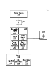
Fig. 2 shows details of the tag 14, in accordance with a specific non-limiting
embodiment of
the present invention. The tag 14 comprises a memory 202, a transceiver 204
(including an
antenna), a controller 206 and a power source 208.
8
CA 3014582 2018-08-17
The memory 202 stores a current signature 212. In addition, the memory 202 may
store a
program for execution by the controller 206, including computer-readable
program code for
causing the controller 206 to execute various steps and achieve wide-ranging
functionality.
In a non-limiting embodiment, the current signature 212 can take the form of a
bit pattern
having a certain number of bits. In accordance with an embodiment of the
present invention,
the bit pattern exhibited by the current signature 212 is dynamic, that is to
say the current
signature 212 changes over time.
The controller 206 executes various functions that allow communication to take
place via the
transceiver 204 between the tag 14 and an external reader such as the reader
12. In what
follows, communications will hereinafter be referred to as occurring with the
reader 12
although it will be appreciated that the tag 14 may communicate similarly with
other external
readers that it encounters.
As part of its functionality, the controller 206 is operative to retrieve the
current signature
212 from the memory 202 and to release the current signature 212 via the
transceiver 204.
Alternatively, depending on the computational capabilities of the controller
206, the
controller 206 can be operative to compute the current signature 212 on demand
and to
release via the transceiver 204 the current signature 212 so computed.
It is recalled that in this embodiment, the current signature 212 is dynamic.
Accordingly, the
controller 206 is operative to communicate with the memory 202 in order to
change the bit
pattern of the current signature 212 stored in the memory 202. This can be
achieved by
executing diverse functionality that will be described in greater detail later
on, and which
may include implementing functional elements such as an encryption engine 222,
a counter
230, a pseudo-random number generator 240, a geo-location module 250 and a
clock module
260, among others.
The configuration of the power source 208 and its inter-relationship with the
controller 206
depend on whether the tag 14 is categorized as "passive", "active" or
somewhere in between.
Specifically, the tag 14 may be designed as "passive", whereby transmissions
of the current
9
CA 3014582 2018-08-17
signature 212 via the transceiver 204 are effected in response to detection of
a burst of energy
via the transceiver 204, such burst of energy typically coming from the reader
12 issuing a
"read request". In this case, the controller 206 only needs to be powered
during the short
time period following the detection of the burst. In fact, the burst itself
can charge the power
source 208 for a brief period, enough to allow the controller 206 to cause
transmission of the
current signature 212 via the transceiver 204 in response to the read request.
The current
signature 212 may be extracted from the memory 202 or it may be generated on
demand,
upon receipt of the read request.
Alternatively, in some embodiments of an "active" tag, transmissions of the
current signature
212 via the transceiver 204 are similarly effected in response to detection of
a read request
via the transceiver 204. In this case, the availability of the power source
208 allows the
controller 206 to transmit the current signature 212 at a longer range than
for passive devices.
Certain active tags also have the capability to switch into a passive mode of
operation upon
depletion of the power source 208. In other embodiments of an active tag,
transmissions of
the current signature 212 are effected via the transceiver 204 at instances or
intervals that are
controlled by the controller 206. This can be referred to as autonomous (or
unsolicited)
issuance of the current signature 212. To this end, the controller 206 needs
to be
continuously powered from the power source 208.
Active and passive tags may have other features that will be known to those of
skill in the art.
In still other cases, the power source 208 (either continually storing a
charge or accumulating
a sensed charge) can be connected to the controller 206 via a switch 210,
which is optional.
The switch 210 can be toggled between a first state during which an electrical
connection is
established between the power source 208 and the controller 206, and a second
state during
which this electrical connection is broken. The switch 210 is biased in the
second state, and
can be placed into the first state. Toggling into the first state can be
achieved by a burst of
energy that is sensed at a sensor (not shown) or by use of an activation
element. In various
non-limiting embodiments, the activation element may be a touch-sensitive pad
on a surface
of the tag 14, or a mechanical component (e.g., a button). Placing the switch
210 into the
CA 3014582 2018-08-17
first state may also trigger the controller 260 to change the current
signature 212 in the
memory 202.
With reference now to Fig. 3, there is shown conceptually how the current
signature 212
stored in the memory 202 may change over time. Specifically, different
versions of the
current signature 212 (denoted SA and SB) are generated by an encoding
function 302
implemented by the controller 206. For notational convenience, the current
signature 212 is
used to denote which of the two signatures SA, SB is currently stored in the
memory 202. The
encoding function 302 generates the signatures SA and SB by encoding a common
"identifier"
(denoted ID) with a respective "additional data set" (denoted DA and DB) at
respective time
instants (denoted TA and TB). Thus, at TA, the signature SA is generated by
encoding the
identifier ID with the additional data set DA, whereas at TB, the signature SB
is generated by
encoding the identifier ID with the additional data set DB. While in this
example, two time
instants are shown and described, this is solely for simplicity, and it should
be understood
that in actuality, the current signature 212 may change many times.
The identifier ID is constant, and in one embodiment conveys information about
the item,
animal, vehicle, piece of equipment, etc., to which the tag 14 is affixed.
Examples of such
information include, without limitation: a serial number, a universal product
code (UPC), a
vehicle registration number (VIN) and a customized identifier. In another
embodiment, the
identifier ID conveys information about an expected user of the vehicle,
clothing or mobile
communication device, computer, restricted access area, network, etc., to
which the tag 14 is
affixed. Examples of such information include, without limitation: a name, an
ID number, a
driver's license number, an account number and login credentials.
In accordance with a non-limiting embodiment of the present invention, the
additional data
sets DA and DB are different, which makes both signatures SA, SB different. In
fact, the two
signatures SA, SB will appear scrambled relative to one another due to use of
the encryption
engine 222 within the encoding function 302. More specifically, the signatures
SA and SB
can be generated from the additional data sets DA and DB in a variety of ways,
two of which
will be described herein below.
11
CA 3014582 2018-08-17
First Approach
In a first approach, described with reference to Fig. 4A, the identifier ID is
encrypted by the
encryption engine 222 with a dynamic key ¨ represented by the additional data
sets DA, DB
themselves, resulting in the two signatures SA, SB. The two signatures SA, SB
will be
different because the additional data sets DA, DB are different. In fact, they
will appear
scrambled relative to one another when observed by someone who has not applied
a
decryption process using a counterpart to the keys used by the encryption
engine 222.
It will be noted that in order to make the first approach practical, the
reader 12 needs to have
knowledge of which key (i.e., which of the additional data sets DA, DB) was
used for
encryption of a received one of the signatures SA, SB, in order to effect
proper decryption and
recover the identifier I. For this purpose, in order to assist the reader 12
in identifying the
correct key to be used for decryption, and with reference again to Fig. 2, the
current signature
212 may be accompanied by an index 214 also stored in the memory 202. The
index 214
may point the reader 12 to the correct key to be used. The reader 12 may have
access to a
key database (not shown) for this purpose.
For example, consider the case where the keys (in this case, the additional
data sets DA, DB)
correspond to outputs of the pseudo-random number generator 240 having a seed
known a
priori to the tag 14 and to the reader 12. Here, at TA, the index 214 may
indicate the
sequential position in the output of the pseudo-random number generator 240
that
corresponds to the additional data set DA, while at TB, the index 214 may
indicate the
sequential position in the output of the pseudo-random number generator 240
that
corresponds to the additional data set DB. The reader 12 can then easily find
the value
occupying the correct sequential position in the output of an identical local
pseudo-random
number generator and effect successful decryption of the received signature
(SA or Su).
Alternatively, the keys (in this case, the additional data sets DA, DB) are
provided by the
reader 12. This can be done where the reader 12 (or an entity associated
therewith) decides
12
CA 3014582 2018-08-17
that a change in the current signature 212 is required. As a variant, the
reader 12 may issue a
trigger which, when received by the controller 206, causes the controller 206
to effect a
change in the current signature 212. In such cases, changes to the key (and
thus to the
current signature 212) are effected by the controller 206 in response to
triggers received from
the reader 12.
Second Approach
For other applications, the approach of Fig. 4B may be useful. Here, the
identifier ID is
augmented with differing scrambling codes (denoted CA and CB), and then
encrypted by the
encryption engine 222 with a common key (denoted K), thus producing the two
signatures
SA, SB. The "additional data set" DA used for encryption at TA is therefore
composed of the
key K and the scrambling code CA, while the "additional data set" DB used for
encryption at
TB is composed of the same key K and the scrambling code CB. The encryption
process can
be designed so that small differences (in terms of the number of bits where
there is a
difference) between the scrambling codes CA and CB will cause large
differences (in terms of
the number of bits where there is a difference) in the resultant signatures SA
and SB. Thus,
the scrambling codes CA, CB have the effect of scrambling (i.e., randomizing)
the resultant
signatures SA, SB.
The controller 206 is responsible for determining which scrambling code is to
be used to
generate a particular signature at a particular time instant. The current
version of the
scrambling code can be stored in the memory 202 and is denoted 220 for
convenience. It
will be appreciated based on the above description that the scrambling code CA
Corresponds
to the current scrambling code 220 at TA and that the scrambling code CB
corresponds to the
current scrambling code 220 at TB.
Continuing with the second approach, several classes of embodiments are
contemplated for
changing the current scrambling code 220. In a first class of embodiments
relevant to the
approach of Fig. 4B, the current scrambling code 220 is changed in a way that
can be
13
CA 3014582 2018-08-17
predicted by the reader 12, that is to say, where the reader 12 (or an entity
associated
therewith) has knowledge of how each successive scrambling code is generated.
For example, the current scrambling code 220 can be changed each time (or,
generally, each
Nth time where N? 1) that the controller 206 receives a read request or
releases the current
signature 212 in response to a read request. This can ensure that the current
signature 212 is
different each Nth time that the controller 206 receives a read request.
Alternatively, the
current scrambling code 220 is changed every the current scrambling code 220
can be
changed every set period of time (ex. every N seconds, minutes, hours, days,
etc.). The
variations in the current scrambling code 220 may governed in a variety of
ways that are
predictable to the reader 12. For example, the controller 206 may implement a
counter 230,
whose output is incremented (by a step size that can equal unity or can be
negative, for
example) after each Nth time that the controller 206 responds to a read
request received from
a nearby reader (or each N seconds, etc.). If the current scrambling code 220
is set to
correspond to the current output of the counter 230, then the scrambling codes
Cm CB used to
generate the two signatures SA, SB will differ by the step size.
Alternatively, the controller 206 may implement the aforesaid pseudo-random
number
generator 240, which produces an output that depends on one or more previous
values of the
output and on a seed. If the current scrambling code 220 is set to correspond
to the current
output of the pseudo-random number generator 240, then the scrambling codes
CA, CB used
to generate the two signatures SA, SB will differ in accordance with the
characteristics of the
pseudo-random number generator 240.
Other variants will become apparent to those of skill in the art without
departing from the
scope of the present invention.
In a second class of embodiments relevant to the approach of Fig. 4B, the
additional data sets
DA, DB are not only predicted by the reader 12 but are actually controlled by
the reader 12.
This can be useful where the reader 12 (or an entity associated therewith)
decides that a
change in the current signature 212 is required. Alternatively, and
recognizing that the key K
14
CA 3014582 2018-08-17
is common to both of the additional data sets DA, DB, the reader 12 could
supply the unique
portions of the additional data sets DA, DB, namely the scrambling codes CA,
Cs.
As a variant, the reader 12 may simply issue a trigger which, when received by
the controller
206, causes the controller 206 to effect a change in the current signature
212. In such cases,
changes to the current signature 212 are effected by the controller 206 in
response to triggers
received from the reader 12.
In a third class of embodiments relevant to the approach of Fig. 4B, it may be
desired to
change the signatures SA, SB in a stochastic way, that is to say, without the
need to follow an
underlying pattern that could be predicted by the reader 12.
For example, the controller 206 may implement the aforementioned geo-location
module
250, which is configured to output a current spatial position of the tag 14 or
of an item or
person to which it is affixed. If the current scrambling code 220 is set to
correspond to the
current output of the geo-location module 250, then the scrambling codes CA,
CB used to
generate the two signatures SA, SB will differ in a stochastic fashion.
Alternatively, the controller 206 may implement a clock module 260, which is
configured to
determine a current time. If the current scrambling code 220 is set to
correspond to a value
measured by the clock module 260 (e.g., number of milliseconds elapsed since
midnight of
the day before), then the scrambling codes CA, CB used to generate the two
signatures SA, SB
will differ in a stochastic fashion.
While the above embodiments have focused on temporal variations in the current
signature
212 stored in the memory 202 of the tag 14, it is also within the scope of the
present
invention for the current signature 212 stored in the memory 202 of two
different tags to be
different at a common time instant (e.g., at a time when the tags are being
read in bulk). This
can be referred to as spatial scrambling. More particularly, with reference to
Fig. 5, a
plurality of tags 514 are affixed to a number of units 506 of a particular
article. The units
506 may be arranged on a pallet 508, on a shelf or in a container, for
example. To take a
CA 3014582 2018-08-17
simple non-limiting example, the article in question can be a pair of denim
jeans of a certain
brand, size, style and color. Of course, the article could be any other item
of which multiple
units are available, such as a consumer product, food product, vehicle, etc.
Other
possibilities that may appear to one of skill in the art are within the scope
of the present
invention.
The tags 514 store respective signatures 510 that are each derived by
encrypting an identifier
550 (common to the tags 514) and a respective one of a plurality of current
scrambling codes
520 (different for the various tags 514) with a common key. The common
identifier 550 can
be used to identify the article in question (in this case, a pair of jeans of
a particular brand,
size, style, color, etc.). To ensure that the signatures 510 appear scrambled
while
nevertheless encrypting the common identifier 550, approaches such as the
following may be
taken.
In one non-limiting approach, a centralized entity generates unique current
scrambling codes
520 and unique signatures 510 for each of the tags 514. The tags 514 are pre-
loaded with
their respective unique signatures 510 before being affixed to the units 506.
In this approach,
the unique signatures 510 are fixed, as a result of which the tags 514 can be
greatly
simplified since they do not need to perform any processing functions.
Practically speaking,
this allows a distributor to purchase a plurality of tags 514 that have been
pre-loaded with
unique signatures 510 in order to securely identify the units 516 of a
particular article.
In another non-limiting approach, the tags 514 may each operate a respective
clock module
which, though structurally identical, may output different results, due to
differences in
oscillation characteristics (e.g., the oscillation crystals used, etc.) This
will result in
differences between the current scrambling code produced based on an output of
the clock
module of one of the tags 514 and the current scrambling code produced based
on an output
of the clock module of another one of the tags 514, albeit at the same time
instant.
In yet another non-limiting approach, different current scrambling codes 520
can be
produced as a result of the tags 514 each operating a respective pseudo-random
number
16
CA 3014582 2018-08-17
generator using a different seed, which could be pre-loaded by the above
mentioned
centralized entity.
Still other ways of making the current scrambling codes 520 different among
the various tags
514 are within the scope of the present invention.
It is noted that the signatures 510 will tend to be widely varying even if the
differences in the
current scrambling codes 520 used to generate them are small, this effect
being due to
application of an encryption process, even when a common key is used. In fact,
to an
observer not equipped with the complementary key for decryption (which may be
the same
as the common key in a symmetric encryption scenario), the signatures 510
corresponding to
the various units 506 on the pallet 508 will appear scrambled. This provides
protection
against external observers (e.g., thieves, corporate intelligence
investigators) who may have
gathered knowledge of signatures output by one or more units of the article in
the past (e.g.,
from a previous purchase ¨ or knowledge of a previous shipment¨ of the same
brand, size,
style and color of jeans) and are now on the lookout for the presence of units
of the same
article on the pallet 508. On the other hand, by using the appropriate key in
order to decrypt
any of the signatures 510, then no matter how diverse one such signature is
from another, the
common identifier 550 will be revealed alongside a stochastically derived
scrambling code.
In order to allow the reader 12 to identify the appropriate key for
decryption, each of the
signatures 510 may be accompanied by the aforesaid index 214 stored in the
memory 202.
The index 214 may point the reader 12 to the correct key for decryption. For
example, the
index 214 could be a piece of public information such as a manufacturer
identification code
or a product category, such information being common to the units 506 but
sufficiently
generic to be of little value to an outside observer. This will allow the
reader 12 (or an entity
associated therewith) to select the correct key for decryption by accessing a
table of keys (not
shown) on the basis of the index. Such an approach can be useful to accelerate
the
decryption process and reduce the incidence of false positives (successful but
inadvertent
decryption of the wrong identifier) when multiple keys are potentially
available to the reader
12.
17
CA 3014582 2018-08-17
It should also be appreciated that the signatures 510 on the various tags 514
can, in addition,
be designed to change in a dynamic fashion (as described earlier), thus
providing, in addition
to spatial scrambling of the signatures 510, temporal scrambling of the
signatures 510 that
leads to even greater security vis-à-vis external observation.
In view of the foregoing, it should thus be appreciated that a common
identifier, which is
encoded within a plurality of signatures that vary over space (for multiple
tags) and/or time
(for the same tag), can be extracted by the reader 12 (or an entity associated
therewith) by
utilizing the appropriate key for decryption. This allows the reader 12 (or an
entity
associated therewith) to perform
(I) validation of the identifier based on the signature and/or the scrambling
code; and/or
(II) an action related to identification, based on the identifier.
Both of these scenarios, which are not mutually exclusive, are now described
in some detail.
In scenario (I), a dynamic scrambling code is used in the generation of a
signature that
continually encodes the same identifier, and it is of interest to recover the
current scrambling
code to detect a potential instance of tag cloning. Accordingly, with
reference to Fig. 6A,
there is shown a system that is similar to the system of Fig. 1. In addition,
the system of Fig.
6A comprises a processing entity 610 that implements a validation operation,
as will be
described herein below. In various embodiments, the processing entity 610
referred to above
may be connected to the reader 12, or it may be a remote entity. Such a remote
entity may be
reachable over a network, or it may be integrated with the reader 12. The
system of Fig. 6A
also includes a storage entity, such as a database 602, that is accessible to
the processing
entity 610 and stores a plurality of records 604, each associated with a
respective identifier.
For the purposes of the present example, one can consider that each identifier
for which there
exists a record in the database 602 is indicative of a privilege to access
certain property or
18
CA 3014582 2018-08-17
make certain transactions, although other scenarios are possible without
departing from the
scope of the present invention.
In accordance with one embodiment of the present invention, each of the
records 604 also
comprises a field 606 indicative of zero or more scrambling codes 608 that
were encoded in
signatures which were previously received and which encoded the respective
identifier for
that record. Thus, receipt of a particular signature that encodes the
identifier in a given one
of the records 604 as well as one of the scrambling code(s) 608 stored in the
corresponding
field 606 will indicate that the particular signature has been previously
received and therefore
its instant receipt may be indicative that a cloning attempt has been made.
More specifically, with reference to the flowchart in Fig. 7A, consider what
happens
following step 710 when a signature Sx is received at a particular time
instant by the reader
12. At the time of receipt, whether the signature Sx encodes any particular
identifier or
scrambling code is unknown to the reader 12. At step 730, an attempt to
decrypt the
signature Sx is made by the processing entity 610 using a decryption key Kx.
The decryption
key Kx may be known in advance to the processing entity 610. Alternatively, as
shown in
step 720, the signature Sx may be accompanied by an index that allows the
processing entity
610 to determine the appropriate decryption key Kx. The result of the
decryption attempt at
step 730 is a candidate identifier Ix and a candidate scrambling code, denoted
Cx=
At step 740, the processing entity 610 consults the database 602 based on the
candidate
identifier Ix in an attempt to identify a corresponding record and extract
therefrom a list of
scrambling code(s) that have been received in the past in association with the
candidate
identifier Ix. For the purposes of the present example, it is useful to assume
that such a
record exists (i.e., the "YES" branch is taken out of step 740), but if there
is no such record,
this may indicate that there is a high-level failure requiring further action.
At step 750, the
processing entity 610 compares the candidate scrambling code Cx to the
scrambling code(s)
608 in the field 606 of the record identified at step 740 and corresponding to
identifier Ix.
19
CA 3014582 2018-08-17
If there is a match, this indicates that the scrambling code Cx has been used
in the past in
association with the identifier Ix. Under certain conditions, this may lead
the processing
entity 610 to conclude that the validation operation was unsuccessful.
For example, if the signature Sx was expected to change at least as often as
every time that
the tag on which it is stored was read, then the fact that the scrambling code
Cx matches one
of the scrambling code(s) 608 stored in the field 606 of the record
corresponding to identifier
Ix may lead the processing entity 610 to conclude that the validation
operation was
unsuccessful. Alternatively, if the signature Sx was expected to change every
Nth time that
the tag on which it is stored was read, then the processing entity 610 may
look at how many
of the scrambling code(s) 608 stored in the field 606 of the record
corresponding to identifier
Ix correspond to the scrambling code Cx, and if this number is greater than or
equal to N, this
may lead the processing entity 610 to conclude that the validation operation
was
unsuccessful. Alternatively still, if the signature Sx was expected to change
at least as often
as every N seconds etc., then the processing entity 610 may look at how long
ago it has been
since a matching one of the scrambling code(s) 608 was first stored in the
field 606 of the
record corresponding to identifier Ix, and if this time interval is greater
than or equal to a pre-
determined number of seconds, minutes, hours, days, etc., this may lead the
processing entity
610 to conclude that the validation operation was unsuccessful.
Where a conclusion is reached that the validation operation was unsuccessful,
the privilege to
access the property or make transactions may be revoked or at least questioned
on the basis
of suspected tag cloning.
On the other hand, if there is no match between the scrambling code Cx and any
of the
scrambling code(s) 608 stored in the field 606 of the record corresponding to
identifier Ix,
this may lead the processing entity 610 to conclude that the validation
operation was
potentially successful. In such a case, the default privilege to access the
property or make
transactions may be granted (or at least not revoked on the basis of suspected
tag cloning).
CA 3014582 2018-08-17
In accordance with an alternative embodiment of the present invention, the
field 606 in the
record associated with each particular identifier may be indicative of an
"expected"
scrambling code, i.e., the scrambling code that should (under valid
circumstances) be
encoded in a signature received from a tag that encodes the particular
identifier.
Alternatively, the field 606 in the record associated with each particular
identifier may be
indicative of an "expected" signature, i.e., the signature that should (under
valid
circumstances) be received from a tag that encodes the particular identifier.
Thus, upon
receipt of the signature Sx, if it is found to correspond to the expected
signature (or if the
scrambling code Cx is found to correspond to the expected scrambling code),
this may lead
the processing entity 610 to conclude that the validation operation was
potentially successful.
On the other hand, if there is no match between the signature Sx and the
expected signature
stored in the database 602 (or between the scrambling code Cx and the expected
scrambling
code), this may lead the processing entity 610 to conclude that the validation
operation was
unsuccessful.
It should be appreciated that in the above alternative embodiments, the
processing entity 610
may obtain knowledge of the expected scrambling code or the expected signature
by
implementing plural pseudo-random number generators for each of the
identifiers, analogous
to the pseudo-random number generator 240 implemented by the controller 206 in
a given
tag 14, which produces an output that depends on one or more previous values
of the output
and on a seed. Thus, the next output of the pseudo-random number generator
implemented
by the processing entity 610 for a given identifier allows the processing
entity 610 to predict
the scrambling code (or the signature) that should be received from a tag
legitimately
encoding the given identifier. In another embodiment, the processing entity
610 may know
what is the expected scrambling code / signature because it has instructed the
reader 12 to
cause this expected scrambling code / signature to be stored in the memory of
the tag.
In accordance with an alternative embodiment of the present invention, the
database 602
simply comprises a running list of all signatures that have been received in
the past. Thus,
upon receipt of the signature Sx, if it is found to correspond to one of the
signatures on the
list, this may lead the processing entity 610 to conclude that the validation
operation was
21
CA 3014582 2018-08-17
unsuccessful. On the other hand, if there is no match between the signature Sx
and any of the
signatures stored in the database 602, this may lead the processing entity 610
to conclude that
the validation operation was potentially successful (or at least not
unsuccessful).
It should also be appreciated that having obtained the identifier Ix, the
processing entity 610
may also perform an action related to identification of an item associated
with the particular
tag that encoded the identifier Ix.
In a first example of an action related to identification, the processing
entity 610 may simply
note the fact that the item (bearing the identifier Ix) was encountered in a
vicinity of the
reader 12. This information may be stored in a database (not shown) or sent as
a message,
for example. In an inventory management scenario, the processing entity 610
may consult an
inventory list and "check off" the item as having been located, or may signal
that the
presence of a spurious item (that is not on the inventory list) has been
detected.
In another example of an action related to identification, the processing
entity 610 may
consult another database (not shown) in order to ascertain whether the
identifier is on a list of
identifiers associated with individuals/objects permitted to access, or
prohibited from
accessing, certain property. Examples of property include, without limitation:
computing
equipment, a computer network, a building, a portion of a building, an
entrance, an exit and a
vehicle.
In another example of an action related to identification, the processing
entity 610 may
consult another database (not shown) in order to ascertain whether the
identifier is on a list of
identifiers associated with individuals permitted to effect, or prohibited
from effecting, a
transaction, which could be a financial transaction or a login to controlled
online content, for
example.
Fig. 7B shows a variant where multiple keys are possible but no index (or one
that does not
permit identification of the appropriate decryption key) is provided along
with the signature
Sx. Specifically, taking the "NO" branch after step 750 does not conclude the
validation
22
CA 3014582 2018-08-17
operation. Rather, the validation operation goes through step 770 where a next
key is
selected and then the validation operation returns to step 730, whereby steps
730 through 770
are re-executed until the earlier occurrence of (i) taking the "YES" branch at
step 750 and (ii)
exhaustion of all keys, which can result in the equivalent of taking the "NO"
branch out of
740 (i.e., this may indicate that there is a high-level failure requiring
further action).
It should be appreciated that in the above embodiments, encryption and
decryption can be
effected using various techniques known in the art, including encryption using
a symmetric
key, an asymmetric key pair, a public / private key pair, etc., as well as in
accordance with a
variety of algorithms and protocols For example, RSA and ECC are suitable
examples of
asymmetric encryption algorithms, while AES, DES, and Blowfish are suitable
examples of
symmetric algorithms. Still other possibilities exist and are within the scope
of the present
invention.
In the above example with reference to Figs. 6A, 7A and 7B, although a single
reader was
described and illustrated, it should be appreciated that it is within the
scope of the present
invention to provide a multi-reader architecture, as shown in Fig. 6B. A
plurality of readers
1012 are connected to each other and to a centralized control entity 1010 by a
network 1030,
which can be a public packet-switched network, a VLAN, a set of point-to-point
links, etc.
In such a case, the centralized control entity 1010 (e.g., a network
controller) can implement
the functionality of the processing entities 610, including encryption and
validation. To this
end, the centralized control entity 1010 maintains a master database 1020,
which includes the
equivalent of a consolidated version of various instances of the database 602
previously
described as being associated with the reader 12 in the single-reader
scenario.
Thus, decryption and validation can be performed entirely in the centralized
control entity
1010. Alternatively, certain functionality (such as decryption) can be
performed by the
readers 1012 while other functionality (such as validation) can be performed
by the
centralized control entity 1010. Still alternatively, the processing entities
610 can inter-
operate amongst themselves in the absence of the centralized entity 1010,
thereby to
implement decryption on a local basis, and the validation operation in a joint
fashion. In
23
CA 3014582 2018-08-17
such a distributed scenario, the master database 1020 can still be used, or
the processing
entities 610 can communicate with one another to share information in their
respective
databases 602.
In scenario (II), a dynamic key is used in the generation of a signature that
encodes a constant
identifier, and it is of interest to recover the underlying identifier despite
the time-varying
key. Accordingly, with reference now to Fig. 8, there is shown a system that
is similar to the
system of Fig. 1. In addition, the system of Fig. 8 comprises a processing
entity 810 that
implements an identification operation, as will be described herein below. The
processing
entity 810 may be connected to the reader 12, or it may be a remote entity.
Such a remote
entity may be reachable over a network, or it may be integrated with the
reader 12. It should
be understood that the system in Fig. 8 is being shown separately from the
system in Fig. 6;
however, it is within the scope of the present invention to combine the
functionality of both
systems.
With reference to the flowchart in Fig. 9, consider what happens following
step 910 when a
signature Sy is received from a particular tag at a particular time instant by
the reader 12.
The signature Sy is assumed to have been generated by encrypting an identifier
ly using an
encryption key that varies in a dynamic fashion. To this end, the particular
tag may have
generated the dynamic encryption key based on, for example:
- the output of the aforementioned clock module 260 (e.g., in terms
of seconds, minutes
or hours of elapsed time since an event known also to the processing entity
810);
- the output of the aforementioned geo-location module 250;
- an index;
- a seed for use by a pseudo-random number generator.
Still other possibilities are within the scope of the present invention. The
decryption key can
then be determined based on the above quantity. For example, the decryption
key could be
the above-mentioned output of the clock module or the geo-location module.
Alternatively,
the encryption key could be the output of a table or a pseudo-random number
generator (both
24
CA 3014582 2018-08-17
known to the processing entity 810) based on the above-mentioned seed, or at a
position that
corresponds to the above-mentioned index. In the latter case, the index or
seed can be
supplied along with the signature Sy.
In accordance with the present embodiment, once the signature Sy is read by
the reader 12,
the processing entity 810 is expected to determine the appropriate decryption
key, denoted
Ky. Accordingly, at step 930, the processing entity 810 first determines a
dynamic parameter
that will allow the decryption key Ky to be determined. Examples of the
dynamic parameter
include:
- the output of a clock module (which attempts to emulate the
aforementioned clock
module 260) at the time of receipt of the signature Sy (e.g., in terms of
seconds,
minutes or hours of elapsed time since a known event);
- the output of a geo-location module (which can be similar to the
aforementioned geo-
location module 250);
- the index or seed provided along with the signature Sy.
Next, at step 940, the processing entity 810 obtains the decryption key Ky
based on the
dynamic parameter determined at step 930. For example, where the dynamic
parameter
corresponds to the output of a clock module or a geo-location module, the
decryption key Ky
could be the dynamic parameter itself. Alternatively, where the dynamic
parameter is an
index or a seed, the decryption key Ky could be the output of the
aforementioned table or
pseudo-random number generator known to the processing entity 810, at a
position that
corresponds to the received index, or using the received seed.
Once the decryption key has been obtained, the signature Sy is decrypted at
step 950 using
the decryption key. This leads to extraction of the identifier ly. It is noted
that a scrambling
code was not required in this embodiment, although its use is not disallowed.
CA 3014582 2018-08-17
Having obtained the identifier Iv, the processing entity 810 proceeds to step
960, where it
performs an action related to identification of an item associated with the
particular tag that
encoded the identifier Iy.
In a first example of an action related to identification, the processing
entity 810 may simply
note the fact that the item (bearing the identifier Iy) was encountered in a
vicinity of the
reader 12. This information may be stored in a database (not shown) or sent as
a message,
for example. In an inventory management scenario, the processing entity 810
may consult an
inventory list and "check off" the item as having been located, or may signal
that the
presence of a spurious item (that is not on the inventory list) has been
detected.
In another example of an action related to identification, the processing
entity 810 may
consult another database (not shown) in order to ascertain whether the
identifier is on a list of
identifiers associated with individuals/objects permitted to access, or
prohibited from
accessing, certain property. Examples of property include, without limitation:
computing
equipment, a computer network, a building, a building, a portion of a
building, an entrance,
an exit and a vehicle.
In yet another example of an action related to identification, the processing
entity 810 may
consult another database (not shown) in order to ascertain whether the
identifier is on a list of
identifiers associated with individuals permitted to effect, or prohibited
from effecting, a
transaction, which could be a financial transaction or a login to controlled
online content, for
example.
It should be appreciated that the processing entity 810 may also perform an
action related to
validation of the identifier Iy in conjunction with the above action related
to identification.
Specifically, in accordance with one embodiment of the present invention, the
processing
entity may consult a variant of the aforementioned database 602, where each of
the records
604 now includes a field indicative of zero or more signatures which were
previously
received and which encoded the respective identifier for that record. Thus,
receipt of a
particular signature that encodes the identifier in a given one of the records
604 as well as
26
CA 3014582 2018-08-17
one of the signature(s) stored in the corresponding field will indicate that
the particular
signature has been previously received and therefore its instant receipt may
be indicative that
a cloning attempt has been made.
In the above example with reference to Figs. 8 and 9, although a single reader
was described
and illustrated, it should be appreciated that it is within the scope of the
present invention to
provide a multi-reader architecture, as in Fig. 6B.
Also, those skilled in the art will appreciate that in some embodiments, the
functionality of
any or all of the processing entity 610, the processing entity 810, the reader
12 and the
readers 1012 may be implemented using pre-programmed hardware or firmware
elements
(e.g., application specific integrated circuits (ASICs), electrically erasable
programmable
read-only memories (EEPROMs), etc.), or other related components. In other
embodiments,
the functionality of the entity in question may be achieved using a computing
apparatus that
has access to a code memory (not shown) which stores computer-readable program
code for
operation of the computing apparatus, in which case the computer-readable
program code
could be stored on a medium which is fixed, tangible and readable directly by
the entity in
question (e.g., removable diskette, CD-ROM, ROM, fixed disk, USB drive), or
the computer-
readable program code could be stored remotely but transmittable to the entity
in question via
a modem or other interface device (e.g., a communications adapter) connected
to a network
(including, without limitation, the Internet) over a transmission medium,
which may be either
a non-wireless medium (e.g., optical or analog communications lines) or a
wireless medium
(e.g., microwave, infrared or other transmission schemes) or a combination
thereof.
While specific embodiments of the present invention have been described and
illustrated, it
will be apparent to those skilled in the art that numerous modifications and
variations can be
made without departing from the scope of the invention as defined in the
appended claims
27
CA 3014582 2018-08-17