Note: Descriptions are shown in the official language in which they were submitted.
CA 03028005 2018-12-14
WO 2018/009877 PCT/US2017/041214
TITLE OF THE INVENTION
Systems to Automate Adjustment of Water Volume Release To A Toilet Bowl To
Correspond to Bowl Contents, Toilets Including the System and Related Methods
CROSS REFERENCE TO RELATED APPLICATIONS
[0001] This application claims priority to U.S. Provisional Patent Application
No.
62/359,696, filed July 7, 2016, which is hereby incorporated herein by
reference in its
entirety.
BACKGROUND OF THE INVENTION
[0002] Water conservation is rapidly becoming a concern, with both individual
consumers
and local and national governments for numerous economic and environmental
reasons.
Toilet flushing is the single highest use of water in the average home in
geographies where
water flush toilets are predominant. The average person flushes about five
times a day;
thus, toilets make up about 31% of overall household water consumption.
[0003] To aid in managing the amounts of water used, the "dual flush" toilet
was
developed. The dual flush toilet provides its users with a "low volume flush"
option
(usually about 2 to 4.5 liters) and a "high volume" flush option (usually
about 4 to about 9
liters). The option selected depends on the contents of the toilet bowl after
use, with the
flush disposal of liquid waste requiring only use of the "low volume" option
while the "high
volume" option could be used for solid waste disposal. When used properly, the
dual flush
toilet can reduce consumption of water by as much as 50%.
[0004] However, the dual flush toilet is imperfect in that selection of "low"
versus "high"
flush volume is left to the discretion of the human user, who often forgets or
becomes
confused and inadvertently uses the "high flush" volume in circumstances where
the only
low flush volume is needed.
[0005] Several prior art attempts to remove the decision from the users'
purview by
developing toilet bowls that are able to detect the toilet contents and alter
the flush have
been made. These attempts have primarily focused on use of infrared detection
systems
within or at the inlet of the bowl and/or detection of indirect data
permitting a probable
inference of the contents of the bowl, for example, the proximity of the user
to the toilet, the
usage time, and/or the presence/absence of "fecal gases."
1
CA 03028005 2018-12-14
WO 2018/009877 PCT/US2017/041214
[0006] For example, U.S. Patent No. 8,434,172 B2, titled "Dual Flush
Electronic Flush
Valve," granted May 7, 2013, describes use of an infrared sensor that
periodically "polls"
the location of the toilet user during toilet use to determine if the user is
primarily located in
a "short zone" or a "long zone" during use. If the user was predominately in
the short zone,
i.e., closer to the toilet, the system assumes that the user deposited solid
waste, and a longer
flush with more water is automatically used. If the user was predominately in
the long zone,
i.e., farther from the toilet, the system assumes that the user deposited
liquid waste and a
shorter flush with less water is automatically employed.
[0007] U.S. Patent No. 6,226,807, titled "System and Method For A Reduced
Water
Consumption Vacuum Toilet," discloses a vacuum toilet that contains a weight
sensor to
sense the amount of weight applied to the bowl of the toilet. The sensor
detects whether the
user is standing or sitting when using the toilet by measuring the presence or
absence of
weight applied to the bowl. If weight is detected, a flush control unit
connected to the
sensor commands that a standard amount of water is used to flush the toilet.
If the sensor
detects no weight (indicating that the user has stood), the flush control unit
commands a
small amount of water to be used in the flush.
[0008] In another example, U.S. Patent No. 4,707,867, titled "Toilet-Flushing
Control
Apparatus," teaches an apparatus that includes a detector (optical, heat
sensor, or other
detector that detects the presence of a user on the toilet), a delay circuit,
a judging circuit, a
first timer, a second timer, and a flush valve. The detector detects that a
person is using a
toilet, and outputs a signal which is input to the delay circuit. Upon lapse
of a
predetermined time after receiving this signal, the delay circuit supplies a
signal to the
judging circuit. When the signal of the detector lasts shorter than a
reference time, the
judging circuit determines that the toilet user has urinated. Conversely, when
this signal
lasts for the reference time or a longer time, the judging circuit determines
that the toilet
user has defecated. In the first case, the first timer is operated, and the
flush valve opens for
the time set to the first timer, thereby flushing the toilet. In the second
case, the second timer
is operated, and the flush valve opens for the time set to the second timer,
thus flushing the
toilet. The time set to the first timer is shorter than that set to the second
timer. Hence, the
toilet is flushed with a small amount of water after each urination and with a
large amount
of water after each defecation.
[0009] U.S. Patent Application No. 2008/0078014 Al, titled "Automatic Dual
Flush
Activation," discloses methods of automatically controlling the flush volume
of a flush
2
CA 03028005 2018-12-14
WO 2018/009877 PCT/US2017/041214
valve by detecting the usage time of a toilet user (i.e., the time the user
spends using the
toilet). If the usage time is determined to be "long" when compared to a set
of
preprogrammed values, a full flush volume is used. Conversely, if the usage
time is
determined to be "short," a lesser flush volume is used. The usage time is
determined by
timing the presence of the user on/near the toilet using any one of a variety
of sensor type:
infrared, capacitance, weight, thermal, motion, or combination thereof
[0010] EP 0 453 702 Al, titled "An Automatic Flushing Device for a Flush
Toilet,"
discloses an automatic flushing device for a flush toilet that includes an
infrared sensor and
an electronic circuit connected with the infrared sensor. The infrared sensor
detects the
length of time the toilet has been used and actuates the electronic circuit to
energize a coil to
move magnetically up a round block connected with a rhomboidal ball which
blocks an
outlet capable of dispensing three flush volumes. Depending on the amount of
time the user
has spent on the toilet, the tank is unblocked for the corresponding
appropriate flush
volume.
[0011] JPH 0270839, titled "Water Saving Device of Tank System Water Closet,"
describes
a device that detects whether the user has urinated or defecated, based upon
the user's stay
on the toilet, and automatically adjusts the "constitution of the flush" to
save water.
[0012] DE 19825229 Cl, granted February 17, 2000, and titled "Lavatory Flush
Regulating
System" describes a device that has a sensor unit to detect the bowl's
contents and provide
information for automatic dosing of flush water dependent upon the content.
The sensor
unit is a gas sensor that recognizes fecal gases. The sensor's signals are
processed in a
control unit, which operates a valve to supply a suitable optimum water volume
for a flush
to the lavatory bowl.
[0013] Water is also unnecessarily consumed when a toilet "runs" ¨ that is,
small amounts
of water constantly run or flow into the bowl from the tank as a consequence
of a leaky
valve, malfunctioning float arm or other malfunction. Attempts to monitor
toilets for this
malfunction have been made, for example, U.S. Patent No. 8,310,369 (the '369
patent). The
'369 patent teaches use of a sensor that produces a signal having an amplitude
corresponding to sound and/or vibration detected by the sensor, and which may
include a
piezo-electric sensor to detect or monitor leaks.
[0014] Thus, there remains a need in the art for a system that can be used in
conjunction
with a water flush toilet that automatically, without user participation,
adjusts the flow
volume of water into the toilet bowl depending on the contents or state of the
toilet bowl.
3
CA 03028005 2018-12-14
WO 2018/009877 PCT/US2017/041214
BRIEF SUMMARY OF THE INVENTION
[0015] Advantageously, the technology of the invention removes from the water
flush toilet
user the conundrum of deciding, among the possible flush volumes he can
select, which to
use depending on the contents of the toilet bowl. As a consequence, increased
water
conservation is achieved, since each flush utilizes the least volume of water
necessary to
clear the bowl of the identified waste. Similarly, the system of the invention
can be adapted
to detect, for example, a clog of the toilet bowl outlet and/or a leaking
flush valve, and
"automatically," without human intervention, reduce the volume of water flow
to the bowl
(or tank) to zero.
[0016] Specifically, the invention described herein includes a water-flush
toilet that includes
a toilet bowl that is in fluid communication with a water source and is
mounted with a
sensor system. The sensor system may include a transducer capable of
transmitting an
ultrasonic signal and receiving a return signal. The sensor system may include
a transmitter
to transmit an ultrasonic signal and a receiver to receive an ultrasonic
signal. The sensor
system is configured to measure a Time of Flight of the signal to obtain a
Time of Flight
measurement. Time of Flight (ToF) describes a variety of methods that measure
the time
that it takes for an object, particle, acoustic wave, electromagnetic wave, or
other wave to
travel a distance through a medium. In an embodiment of the invention, Time of
Flight
refers to the time it takes for a sensor signal, such as an ultrasonic signal,
to travel from and
return to the sensor or to travel from a transmitter to a receiver. A
microcontroller is
electrically connected to the sensor system and is configured to receive and
process the ToF
measurement using an algorithm to determine a bowl status. The toilet also
includes at least
one water valve that is disposed between the bowl and the water source, and
that is
electrically connected to the microcontroller for instructing the at least one
water valve to
move from a first position to a second position for a duration of time,
wherein the duration
of time corresponds to the bowl status.
[0017] Systems that can be mounted to a toilet including the sensor,
microcontroller and
optionally the at least one valve, as described above are also described.
[0018] Also included is a method of adjusting a volume of water released into
a toilet bowl
to correspond to a bowl status in a water flush toilet. In an embodiment, the
method
includes transmitting an ultrasonic signal from a transmitter that is mounted
on a toilet bowl
toward the contents of the toilet bowl and receiving the ultrasonic signal.
Upon receipt of
4
CA 03028005 2018-12-14
WO 2018/009877 PCT/US2017/041214
the signal, a ToF measurement is electronically communicated to a
microcontroller. The
microcontroller applies an algorithm that determines a bowl state
corresponding to the ToF
measurement and electronically instructs at least one electromechanically
operated valve
that is in fluid communication with the toilet bowl to move from a first
position to a second
position for a duration of time, wherein the duration of time corresponds to
the bowl status.
Upon the passage of the duration of time, the at least one electromechanically
operated
valve is moved from the second position to the first position.
[0019] Also included are methods of increasing the water conservation of a
toilet, methods
of detecting and ameliorating water waste from a malfunctioning toilet,
methods of
preventing the release of sewer gases into the environment, and methods of
monitoring
toilets in commercial applications.
[0020] According to an embodiment, a water flush toilet may include a toilet
bowl that is in
fluid communication with a water source and is mounted with a sensor
comprising that
comprises a transmitter capable of transmitting an ultrasonic signal, and a
receiver capable
of receiving an ultrasonic signal, wherein the sensor is configured to measure
a Time of
Flight (ToF) of the signal to obtain a ToF measurement, a microcontroller
electrically
connected to the sensor that is configured to receive and process the ToF
measurement to
determine a bowl status; and at least one water valve that is disposed between
the bowl and
the water source, and is electrically connected to the microcontroller for
instructing the at
least one water valve to move from a first position to a second position for a
duration of
time, wherein the duration of time corresponds to the bowl status.
[0021] According to embodiments, the water flush toilet may include a sensor
that is a
piezo-ceramic sensor. The sensor may be mounted at an exterior of the toilet
bowl. The
sensor may be mounted at an interior of the toilet bowl. The sensor may be
mounted at a
bottom center of the toilet bowl. The transmitter may be mounted on a first
side of the bowl,
and the receiver may be mounted on a second side of the bowl that is opposite
the first side.
The water valve may be an electromechanically operated valve. The water valve
may be a
solenoid valve. The water valve may be a flush valve. The water valve may be a
water
source valve.
[0022] According to embodiments, the bowl status may be selected from:
"liquid," "solids,"
and "intermediary." The bowl status may be "liquid" and the flush valve may be
moved
from a closed position to an open position for a duration of time to release a
sufficient
amount of water to clear the bowl. The bowl status may be "low water" and the
flush valve
CA 03028005 2018-12-14
WO 2018/009877 PCT/US2017/041214
may be moved from a closed position to an open position for a duration of time
to release a
sufficient amount of water to restore a water seal. The bowl status may be
"solids" and the
flush valve may be moved from a closed position to an open position for a
duration of time
to release a sufficient amount of water to clear the bowl. The bowl status may
be
"intermediary" and the flush valve may be moved from a closed position to an
open position
for a duration of time to release a sufficient amount of water to clear the
bowl. The bowl
status may be selected from "leak," "liquid clog," "solid clog," and "object."
The water
valve may be moved from an open position to a closed position.
[0023] According to embodiments, the toilet may include a secondary sensor for
detecting
the presence of a user on or in a proximity of the toilet bowl that is
electrically connected to
the microcontroller. The secondary sensor may be an infrared (IR) sensor for
detecting the
presence of a user in front of the toilet bowl. The secondary sensor may be an
infrared (IR)
sensor for detecting the deposit of bowl contents into the toilet bowl.
[0024] According to an embodiment, a system for mounting on a water flush
toilet may
include a sensor electrically connected to a microcontroller including a
transmitter to
transmit an ultrasonic signal, and a receiver to receive the ultrasonic
signal; wherein the
sensor, in use, is configured to generate a ToF measurement of the signal; and
a
microcontroller that is configured to receive and process the ToF measurement
to determine
a toilet bowl status in use and is electrically connectable to at least one
water valve of a
water flush toilet.
[0025] According to embodiments, the sensor of the system may be configured
so, in use,
the transmitter is mountable on a first side of the toilet bowl and the
receiver is mountable
on a second side of the bowl that is opposite the first side. The sensor may
be a piezo-
ceramic sensor.
[0026] According to embodiments, the system may include a secondary sensor for
detecting
the presence of a user on or in a proximity of the toilet bowl that is
electrically connectable
to the microcontroller. The secondary sensor may be an infrared (IR) sensor
for detecting
the presence of a user in front of the toilet bowl. The secondary sensor may
be an infrared
(IR) sensor for detecting the deposit of bowl contents into the toilet bowl.
[0027] According to embodiments, a method of adjusting a volume of water
released into a
toilet bowl to correspond to a bowl status in a water flush toilet may include
transmitting a
ultrasonic signal from a transmitter mounted on the toilet bowl towards a bowl
contents of
the toilet bowl; receiving the ultrasonic signal by a receiver to determine a
ToF
6
CA 03028005 2018-12-14
WO 2018/009877 PCT/US2017/041214
measurement of the signal; electrically conveying the ToF measurement to a
microcontroller
that determines a bowl state corresponding to the ToF measurement and
electronically
instructs at least one electromechanically operated valve that is in fluid
communication with
the toilet bowl to move from a first position to a second position for a
duration of time,
wherein the duration of time corresponds to the toilet bowl status; and moving
the at least
one electromechanically operated valve from the second position to the first
position, upon
passage of the duration of time.
[0028] According to embodiments, the method may include the transmitter and
receiver are
a piezo-ceramic sensor. The determined toilet bowl status may be selected
from: "liquid,"
"solids," and "intermediary." The at least one electromechanically operated
valve may be a
flush valve, the determined toilet bowl status is "liquid," the first position
is a closed
position, the second position is an open position, and the duration of time
releases a
sufficient amount of water to clear the toilet bowl. The at least one
electromechanically
operated valve may be a flush valve, the determined toilet bowl status is
"solids," the first
position is a closed position, the second position is an open position, and
the duration of
time releases a sufficient amount of water to clear the toilet bowl. The at
least one
electromechanically operated valve may be a flush valve, the determined toilet
bowl status
is "intermediary," the first position is a closed position, the second
position is an open
position, and the duration of time releases a sufficient amount of water to
clear the bowl.
The at least one electromechanically operated valve may be a water source
valve, and the
determined toilet bowl status may be selected from "leak," "liquid clog,"
"solid clog," and
"object." The first position may be an open position, the second position is
closed position,
and the duration of time is indefinite.
[0029] According to an embodiment, a method of increasing water conservation
of a water
flush toilet comprising fitting the toilet with any of the disclosed systems.
[0030] According to an embodiment, a method of detecting and ameliorating
water waste in
a water flush toilet comprising periodic activation of a monitoring cycle may
include
transmitting an ultrasonic signal from a transmitter mounted on a toilet bowl
towards a bowl
contents of the toilet bowl; receiving the ultrasonic signal by a receiver
which determines a
ToF measurement of the signal; and electrically conveying the ToF measurement
to a
microcontroller that determines a bowl state corresponding to the ToF
measurement,
wherein when the determined bowl state is "normal," the cycle is ended but
when the
determined bowl state is "leak," the microcontroller electronically instructs
at least one
7
CA 03028005 2018-12-14
WO 2018/009877 PCT/US2017/041214
electromechanically operated valve that is in fluid communication with the
toilet bowl to
move from an open position to a closed position for a duration an indefinite
duration of
time. According to an embodiment, the activation occurs once every 24 hours.
[0031] According to an embodiment, a water-flush toilet may include a toilet
bowl having
an exterior surface and an interior space; and a sensor located on the
exterior surface of the
toilet bowl; wherein the sensor is configured to identify an activity in the
interior space of
the toilet bowl. The sensor may be located on a bottom of the exterior surface
of the toilet
bowl. The sensor may be located on a first side of the exterior surface of the
toilet bowl and
a receiver located on a second side of the exterior surface of the toilet
bowl, wherein the
transmitter and receiver are located at the same axial height on the exterior
surface of the
toilet bowl. The water-flush toilet may include a microcontroller in
communication with the
sensor, the microcontroller configured to initiate a response to the activity.
The activity
identified may be a presence of a solid waste in the toilet bowl and the
response is to open a
valve to perform a high volume flush of the water-flush toilet. The activity
may be a
presence of a liquid waste in the toilet bowl and the response is to open a
valve to perform a
low volume flush of the water-flush toilet. The activity may be a leak into
the toilet bowl
and the response is to close a water supply valve. The activity may be a
presence of a low
water level in the bowl and the response is to open a water supply valve. The
activity may
be a presence of a high water level in the bowl and the response is to close
prevent a flush of
the water-flush toilet. The high water level in the bowl is due to a solid
clog in the water-
flush toilet. The high water level in the bowl is due to a line clog upstream
of the water-
flush toilet. The activity may be presence of intermediary content and the
response is to
perform a low volume flush of the water-flush toilet.
BRIEF DESCRIPTION OF THE SEVERAL VIEWS OF THE DRAWINGS
[0032] The foregoing summary, as well as the following detailed description of
preferred
embodiments of the invention, will be better understood when read in
conjunction with the
appended drawings. For the purpose of illustrating the invention, there is
shown in the
drawings embodiments that are currently preferred. It should be understood,
however, that
the invention is not limited to the precise arrangements and instrumentalities
shown. In the
drawings:
[0033] Fig. 1 is a schematic block diagram that illustrates the hardware of an
embodiment
of the system of the invention and includes a water valve.
8
CA 03028005 2018-12-14
WO 2018/009877 PCT/US2017/041214
[0034] Fig. 2 is a schematic embodying the method of the invention which
includes load
sensing and/or clog detection and corresponding adjustment of flush volume or
water flow.
[0035] Fig. 3 is a second schematic representation of the invention
illustrating a second
embodiment of the system and method of detecting various bowl statuses.
[0036] Fig. 4 is a schematic representation of a cross sectioned toilet bowl
mounted with an
embodiment of the system of the invention, wherein the sensor is configured so
that the
receiver and the transmitter are mounted on opposite sides of the exterior of
the bowl.
[0037] Fig. 5 is an ultrasonic level block diagram illustrating how a ToF
measurement is
obtained in an embodiment of the invention.
[0038] Fig. 5A is a schematic representation of a system for transmitting and
receiving a
signal through a media.
[0039] Fig. 6 is a cross section of a toilet with an intact water seal.
[0040] Fig. 7 is a cross section of a toilet where the water level has become
so low that the
water seal is no longer sufficient.
[0041] Fig. 8 is a photograph of a PVC tube secured to a ceramic tile to form
a small scale
toilet bowl as used in the load sensing experiment.
[0042] Fig. 9 is a timing diagram representative of the signal generated in
the small scale
toilet bowl when only liquid is present.
[0043] Fig. 10 is a timing diagram representative of the signal generated in
the small scale
toilet bowl when solids are present.
[0044] Fig. 11A is a partial cross section of a toilet, according to an
embodiment, with a
normal water lever.
[0045] Fig. 11B is a partial cross section of a toilet, according to an
embodiment, with a low
volume flush.
[0046] Fig. 11C is a partial cross section of a toilet, according to an
embodiment, with a full
volume flush.
[0047] Fig. 11D is a partial cross section of a toilet, according to an
embodiment, with an
overflow water level.
DETAILED DESCRIPTION OF THE INVENTION
[0048] The invention described herein relates to toilets mounted with systems
for adjusting
a water volume released into a toilet bowl depending on the status of the
bowl, i.e., the
amount and/or nature of the bowl contents, whether the outlet of the toilet
bowl is clogged,
9
CA 03028005 2018-12-14
WO 2018/009877 PCT/US2017/041214
preventing the release of sewer gases (e.g., hydrogen sulfide, ammonia,
methane, esters,
carbon monoxide, sulfur dioxide and nitrogen oxides) into the environment,
etc.
[0049] Also included are related methods, including methods of using the
system and
methods of monitoring and ameliorating water waste attributable to leaks or
other toilet
malfunctions, and a system that can, in some embodiments, be retrofitted to
existing and/or
already installed toilets to improve water conservation.
[0050] Advantageously, in an aspect, the invention permits adjustment or
restriction of
flush volume "automatically" by the system itself, wholly in the absence of
any human
intervention. As a result, greater water conservation is achieved, as human
error and/or
negligence is removed as an obstacle. In another beneficial aspect, the
invention provides a
method to periodically monitor the contents of the toilet bowl to detect the
addition of
excess water attributable to a leak or other toilet malfunction. In this
aspect of the
invention, when a "leak" state in a toilet bowl is detected, the system
automatically cuts off
the water supply to the toilet for an indefinite period of time or at least
long enough to
permit the malfunction to be identified and remedied. In this way, needless
water waste is
reduced.
[0051] The invention includes a water flush toilet that is mounted with the
system. By
µ`water flush toilet" it is meant any toilet that disposes of liquid and solid
waste by using
water dispensed from a flush valve to flush it through an outlet of the toilet
bowl to a drain
pipe to another location for disposal. Included are, for example, flush
toilets in sitting or
"Western" configuration or squat configuration, as well as siphoning toilets,
double trap
siphonic toilets, valve closet toilets, washout toilets, and/or shelf-style
toilets.
[0052] In an aspect, the invention includes a system for mounting on a water
flush toilet
and/or a toilet that can be adapted to permit automation of the selection of a
flush volume
depending on the contents of the toilet bowl and/or to permit detection of a
toilet clog, leak
or other similar malfunction and subsequent automated shut down of the water
supply.
[0053] The system includes a sensor. The sensor may include a sensor system
that includes
a sensor and an analog front end. The sensor may be capable of transmitting a
signal, such
as an ultrasonic signal, and receiving a return signal. The analog front end
may initiate the
sensor to transmit a signal toward the toilet bowl contents. The signal may
travel through
the liquid in the toilet bowl and reflect on the intersection of the liquid
and air. The
transducer may accept the reflected signal and/or note and record the absence
of the
reflected signal.
CA 03028005 2018-12-14
WO 2018/009877 PCT/US2017/041214
[0054] The sensor may alternatively include at least a transmitter and a
receiver. The
transmitter is able, in use, to generate and transmit an ultrasonic signal
toward the toilet
bowl contents. The receiver is configured to accept the signal and/or to note
and record the
absence of a signal, in circumstances where the bowl contents are such that
they attenuate or
block the signal. Since the signal and/or reflected signal may be attenuated
or absorbed by
the contents of the bowl, as used herein, the phrase "to receive a signal" in
connection with
the sensor and receiver includes recognition of the absence of a signal and/or
reflected
signal.
[0055] The sensor system is configured to use the information obtained by the
sensor about
the travel of the signal to generate a time of flight measurement ("ToF
measurement"). The
analog front end may use an algorithm to determine the ToF measurement. In
some
embodiments, the ToF measurement generated is an average ToF obtained from
several sets
of information provided by the repeated transmission/reception of a signal. In
another
embodiment, the ToF measurement may be a plurality of ToF data points taken at
time
points during toilet use and/or for a duration of time after toilet use. The
ToF measurement
may also be based on a single ToF data point.
[0056] In use, the sensor system may be mounted on the outside of the bowl or
in the
interior of the bowl. In many embodiments, it is advantageous to mount the
sensor on the
outside of the bowl so as to prevent obstruction or build-up of waste soil,
water minerals,
and/or cleaning agents. The collection of soil, minerals, and/or cleaning
agents may be
unsanitary, may reduce the effectiveness of the sensor, may interfere with the
sensing
element, and/or may deteriorate the sensing element. By locating the sensor
system on the
outside of the bowl, objects within the bowl may not interfere with the
sensing. That is, the
objects will not damage, deteriorate, or reduce the effectiveness of the
sensor.
[0057] In an embodiment, it may be preferred that the sensor is located at the
center bottom
of the toilet bowl (see, e.g., Figure 2, showing position of a sensor
underneath the toilet
bowl) or, the sensor may be configured so that a transmitter is located on a
first side of the
toilet bowl, and a receiver is located on an opposite, second side (see,
Figure 4). In various
embodiments, the transmitter and the receiver may be independently located on
the exterior
or the interior of the bowl. When the sensor (or part of the sensor) is
located exterior of the
bowl, it may be preferred in an embodiment that it is disposed such that it is
directly
adjacent to the ceramic material of the bowl, which is in turn directly
adjacent to the liquid
11
CA 03028005 2018-12-14
WO 2018/009877 PCT/US2017/041214
in the toilet bowl, which in turn interfaces directly with the environment
(air), with no
intervening spaces or layers, as shown in the schematic cross section below:
Air
Liquid
Ceramic
Sensor
[0058] Similarly, if the sensor (or part of the sensor) is located interior of
the bowl, it may
be preferred in an embodiment that it is disposed such that it is affixed
directly to the
ceramic surface of the bowl, and sits directly adjacent to the liquid in the
toilet bowl, which
in turn interfaces directly with the environment (air), with no intervening
spaces or layers,
as shown in the schematic cross section below:
Air
Liquid
Sensor
Ceramic
[0059] The sensor may be any ultrasonic sensor or acoustic-based technology
sensor known
or to be developed in the art. In an embodiment, the sensor is a piezo-ceramic
transducer.
Other sensors may be contemplated, such as, but not limited to, piezo-electric
transducers
and capacitive sensors. In embodiments where the sensor is a capacitive
sensor, the sensor
may operate by comparing changes in capacitance to determine water levels and
bowl
statuses.
[0060] The analog front end may be any device capable of initiating the sensor
to send a
signal and determine a ToF measurement of the signal. An exemplary analog
front end
(AFE) is available from Texas Instruments, Inc., 12500 TI Boulevard, Dallas,
Texas 75243
USA (e.g., TDC 1000 Ultrasonic Sensing Analog Front End (AFE) for Sensing
Applications, the contents of which are incorporated herein by reference).
[0061] The sensor system may include a time-to-digital converter. The time-to-
digital
converter may be a TDC 7200 available from Texas Instruments, Inc. The time-to-
digital
converter may convert the ToF measurement received from the analog front end
to a digital
output for transmitting to the microcontroller.
12
CA 03028005 2018-12-14
WO 2018/009877 PCT/US2017/041214
[0062] The system also includes a microcontroller, which is electrically
connected to the
sensor system. The microcontroller may be located in an upper shell of the
toilet, for
example, near an infrared (IR) sensor on the toilet. Alternatively, the
microcontroller may
be located under the bowl of the toilet or on a top portion of the tank. The
electrical
connection between the microcontroller and the sensor system (and any others
described
herein) may be by traditional hard wiring or wireless electrical connection,
via, for example
WiFi (WLAN or WPAN may be preferred), Bluetooth, BLE, WiMAX connections. The
ToF measurement generated by the sensor system (i.e., by the analog front end)
is
electronically conveyed by the electrical connection to the microcontroller.
The
microcontroller is loaded with an algorithm that permits it to receive and
process the ToF
measurement.
[0063] Once the ToF measurement is input, the microcontroller applies the
algorithm to
determine the state of the bowl ("bowl status"). The algorithm can be written
to facilitate
detection of a variety of bowl statuses since the ToF measurement generated by
the sensor
will differ depending on the state of the bowl contents (e.g., the type of
media, if any,
present in the bowl contents when the ToF measurement was taken). The bowl
contents
may be any solid, liquid, or intermediary (such as tissue), or may be the
absence of content
in the bowl. The variety of bowl statuses may be compared to a "normal"
status. The
"normal" bowl status may be determined based on a ToF measurement at a routine
water
level in the toilet bowl. The routine water level may be a predetermined water
level. The
routine water level may be predetermined based on the toilet model. The
routine water level
may be a water level sufficient to establish a water seal in the toilet. The
"normal" status
may be determined for a particular toilet model, for example, at a
manufacturing facility.
The "normal" status may be a set value (e.g., an average value) chosen from a
set of values
representing the same or similar toilet module.
[0064] It should be appreciated that the ToF measurement corresponding to each
"bowl
status," including the "normal" state, may differ from toilet to toilet,
depending on various
factors, such as bowl structure, fabrication materials and other physical
parameters that
affect the toilet bowl acoustics, as well as the type, quantity and nature of
ToF data that is
aggregated into the ToF measurement. Therefore, the algorithm applied by the
microcontroller will vary. However, at a general level the algorithm includes
a comparison
of the generated ToF measurement to a baseline set of ToF measurements that
includes ToF
measurements corresponding to each of the bowl statuses for which the
programmer wished
13
CA 03028005 2018-12-14
WO 2018/009877 PCT/US2017/041214
to assign an adjusted flush volume, including "normal" state. For example, a
programmer
may assign an adjusted flush volume to a ToF measurement that corresponds to a
leak, clog,
lower volume, etc.
[0065] The various types of bowl statuses can be referenced using any
signifiers, e.g.,
letters, numbers, symbols, etc. However, for convenience, the bowl statuses
herein are
described using simple nouns corresponding to the actual physical contents.
Exemplary
bowl statuses may include, without limitation: (i) the presence of solid waste
in the bowl
water ("solids"); (ii) the presence of liquid only in the bowl ("liquid");
(iii) the presence of
continuous water running/leaking into the bowl ("leak"); (iv) a low water
level in the bowl
("low'); (v) a high water level in the bowl resulting from, for example, a
clog of the toilet
bowl outlet (such as a line clog in a commercial application, where a clog
present in a
downstream portion of the system creates a clog in the upstream array of
toilets) ("liquid
clog"); (vi) a high water level in the bowl resulting from a solid remaining
in the toilet bowl
("solid clog"); (vii) presence of intermediary content, such as paper or
tissue in the bowl
water ("intermediary"); (viii) the presence of a non-feces solid in bowl water
(e.g.,
children's toy, cell phone, or other inappropriate object) ("object"); and
(ix) very low water
level that may permit release of sewer gases ("unsealed").
[0066] The microcontroller may be any known or developed in the art that is
capable of
processing the ToF measurement received from the analog front end to determine
the state
of the bowl ("bowl status"). The microcontroller may determine an action to be
taken by
the toilet system corresponding to the state of the bowl. The microcontroller
may send an
instruction to a flush valve, a water source valve or other valve to open,
close, or remain in
the current state based on the bowl status. Exemplary microcontrollers include
those
available from Texas Instruments, Inc., 12500 TI Boulevard, Dallas, Texas
75243 USA
(Microcontroller MSP 430) or PIC microcontroller from MicroChip of Phoenix,
Arizona.
The microcontroller may be an ARM-based microcontroller.
[0067] In the system of the invention, the microcontroller uses the ToF
measurement within
an algorithm to determine the bowl status, and electronically conveys an
instruction to a
water valve or valves in the system to deliver an appropriate flush volume to
the bowl or to
block the water source to the toilet altogether, so that no additional water
enters the toilet
bowl or tank.
[0068] In an embodiment, the valve is an electromechanically operated valve
that may be
any known or to be developed in the art. In some embodiments it may be
preferred that the
14
CA 03028005 2018-12-14
WO 2018/009877 PCT/US2017/041214
electromechanically operated valves are solenoid valves. The valve may also be
a DC
motor valve or stepper motor valve. If the embodiment involves adjustment of a
flush water
volume in response to a specific bowl status, the valve may be, for example, a
flush valve
that is disposed between the bowl and the water source (e.g., the water mains
or a water
tank) or a water source valve that supplies water to the toilet as a whole.
[0069] In an exemplary embodiment, when the algorithm determines that the bowl
contains
solid waste in the bowl contents (bowl status is "solids"), the
microcontroller electronically
instructs a flush valve or valves to move from a closed position to an open
position for a
duration of time sufficient to release a first flush volume. Correspondingly,
when the
microcontroller determines that the bowl contains liquid (bowl status is
"liquid"), it
electronically instructs the flush valve to open for a duration of time
sufficient to release a
second flush volume, and when the microcontroller determines that the bowl
contains paper
waste or other intermediary material (bowl status is "intermediary"), it
instructs the flush
valve to open for a duration of time sufficient to release a third flush
volume, and so on.
Once the appropriate volume of water has been released, the valve(s) is moved
to a closed
position, and the system resets. Thus, it can be appreciated that the system
may allow for a
customized amount of water to be flushed through the system based on the
specific contents
of the toilet bowl.
[0070] In each instance, the first, second, third, etc., volume may be
different and may be
calibrated to be just enough water ("sufficient") to clear the identified
content from the
bowl. The volume suitable (or sufficient) in each circumstance will differ
depending on the
structure of the particular toilet to which the system is mounted. However, on
average, a
volume of water sufficient to remove solids may be about 2.5 to 6 liters of
water, a volume
of water sufficient to remove liquids alone may be about 0.5 to 5 liters, and
a volume of
water sufficient to remove paper may be about 1 to 5 liters.
[0071] In an embodiment, when the microcontroller determines that the bowl is
receiving
continuous flow of water (i.e., bowl status is "leak") or contains a level of
water higher than
"normal" (i.e., bowl status is "liquid clog" or "solid clog"), it electrically
instructs a water
source valve to move from an open position to a closed position for a duration
of time. By
"water source valve" it is meant a valve that controls the flow of water into
the toilet as a
whole, not just into the toilet bowl.
[0072] In this embodiment, since the aim is for toilet overflow and/or water
waste to be
avoided until the particular malfunction is fixed, the duration of time may be
very long, e.g.,
CA 03028005 2018-12-14
WO 2018/009877 PCT/US2017/041214
1 to 5 hours, 10 hours, 24 hours, 48 hours, 72 hours, 100 hours or an
indefinite amount of
time; in any case, it may be preferred that the valve remains in a closed
position for a
sufficient time to enable the malfunction to be discovered, and repaired and
the system
reset. The system reset may be automatic based on the sensor system detecting
a "normal"
status of the bowl and sending a normal ToF measurement to the
microcontroller.
Alternatively, a user may reset the system manually, such as with a push
button.
[0073] In an embodiment, the system is able to determine when the water level
in the bowl
is very low, i.e., sufficiently low that the mechanical water seal of the
toilet may be
insufficient or altogether lost. By "mechanical water seal" it is meant the
water located in
the toilet trap that prevents sewer gases from escaping back through the bowl
outlet. As is
known in the art, the dimension of a toilet water seal is described in
vertical distance, i.e.,
the vertical distance between the trap dip and the mean level of the water.
Many modern
building codes require a water seal of a minimum vertical distance (e.g., 1.5
inches, 2
inches) between the mean water level and the trap dip to ensure the integrity
and sufficiency
of the water seal in a working system. In this way there is a physical barrier
of water
extending from the weir, through the trap and to 2 inches above the trap dip.
[0074] In this embodiment, the microcontroller is programmed to determine if
the water
level is so low that the water seal is less than the minimum vertical distance
required (bowl
status "low water"). If this condition is detected by the microcontroller, it
electronically
conveys an instruction to a water valve or valves in the system to deliver an
appropriate
flush volume to the bowl, such volume being at least sufficient to restore a
minimum
vertical distance required or desired for the water seal and therefore to
maintain the water
seal. As is appreciated by a person of skill in the art, such volume will vary
depending on
the overall dimensions of the trap and bowl.
[0075] The system may further include other secondary sensors and/or secondary
devices
that are capable of executing additional events in or near the toilet bowl. In
some
embodiments, the system may include more than one ultrasound sensor, and/or an
additional
sensor, such as, e.g., a gas detector, an infrared sensor, a float sensor (to
detect water level),
etc. In some embodiments, the secondary devices may be electrically connected
to the
microcontroller and, upon instruction from the microcontroller, execute an
additional event.
For example, before, after, or during the release of the flush valves, a
secondary device
could be instructed to dispense a cleaner, a deodorizer, an air freshener, a
directional water
16
CA 03028005 2018-12-14
WO 2018/009877 PCT/US2017/041214
stream to clean the bowl or the user, a musical ditty or other sound and/or to
turn on or off a
light or lights.
[0076] In an embodiment, the system includes a secondary sensor for detecting
the presence
of a user on or in a proximity of the toilet bowl. This secondary sensor may
be, for
example, an infrared (IR) sensor that is configured to detect the presence of
a user in front
of the toilet bowl or for detecting the deposit of content into the bowl.
[0077] In an embodiment, an infrared sensor is electrically connected to the
microcontroller; when the infrared sensor detects the presence of a user, it
electrically sends
a signal to the microcontroller, which causes the microcontroller to prompt
the transmitter
of the sensor to begin transmitting the ultrasonic signal toward the bowl
contents. In this
way, the practice of the invention and the inventive methods described herein
can be
executed in the absence of any intentional human intervention.
[0078] As is apparent from the above discussion, the invention also includes
water flush
toilets that are mounted with the system in any permutation of elements
described above.
The system can be mounted on a toilet at the manufacturer and provided to the
consumer as
an integrated product. Alternatively, in some embodiments, the system may be
provided
separately to be retrofitted on existing, pre-installed toilets. In an
embodiment, the system
may also include the electromechanically operated valves or it may include
electronically
effectuated drivers that can be used to convert a conventional mechanical
valve into one that
can be electromechanically operated for use with the system.
[0079] Methods of increasing the water conservation of a toilet that include
mounting the
toilet with any of the systems described herein are also included. For
example, when the
system is used to detect leaks, one or more valves in the toilet may be closed
to prevent
further leakage of water. Additionally, conservation of water may be achieved
through the
programming of various flush volumes, as discussed above, thus allowing the
appropriate
amount of water for the bowl contents to be delivered to the toilet.
[0080] The scope of the invention also includes a method of detecting and
preventing or
ameliorating needless waste of water by providing a way to automatically
monitor a toilet
for high water levels in the toilet bowl or near continuous lower-level
turbulence of the bowl
contents, which is indicative of a leak or the flush valve or other
malfunction. Such
methods include a periodic activation of a monitoring cycle that includes: i)
transmitting an
ultrasonic signal from a transmitter mounted on a toilet bowl toward the
contents of the
toilet bowl; ii) receiving the ultrasonic signal by a receiver that determines
a ToF
17
CA 03028005 2018-12-14
WO 2018/009877 PCT/US2017/041214
measurement of the signal; iii) electrically conveying the ToF measurement to
a
microcontroller that applies an algorithm to determine a bowl state
corresponding to the ToF
measurement.
[0081] If the algorithm applied by the microcontroller indicates that the bowl
state is
"normal," the cycle is ended. If, however, the determined bowl state is "leak"
or "high
water" or "turbulence" or similar, the microcontroller electronically
instructs at least one
electromechanically operated valve that is in fluid communication with the
toilet bowl to
move from an open position to a closed position. The valve may remain closed
until the
malfunction is identified and repaired and the system is reset. The system may
be reset
automatically based on a new ToF measurement indicating a "normal" status or
manually by
the user, as previously described.
[0082] Activation of the monitoring system may be effectuated manually or may
be
programmed to occur at various time intervals, for example, once every 24
hours, once a
week, once a month, etc. The monitoring system may be substantially
continuous, such that
a signal is transmitted and a ToF measurement recorded at programmed
intervals, including
intervals as frequent as every hour. Such substantially continuous monitoring
may detect
statuses such as "leaks" and "clogs" quickly and actuate the valves to open,
close, or remain
in the current state, or to actuate other components in the previously
described manner, until
the status is remedied. The frequency of monitoring may be based on
application. For
example, in commercial use, such as at a sports venue, the system may be
programmed to
send sensor signals frequently during a sporting event and be substantially
dormant or
asleep when the venue is vacant. In other commercial uses, such as offices or
airports, the
system may be programmed to monitor during office hours or high travel time
periods,
respectively, and remain dormant during off-hours. The microcontroller may be
programmed with use schedules determining when the sensor system is monitoring
and
asleep.
[0083] Since water turbulence may indicate water leakage or deposition of
human liquid
waste from a distance, as when the toilet is being used by a male in standing
position, the
microcontroller's algorithm may permit distinction between lower-level
turbulence (leak)
and higher levels of turbulence (standing urination). When liquid is leaking
into the toilet,
either due to a leak in the toilet or through urination by a user, there will
be an increase in
turbulence in the surface of the liquid in the toilet bowl. The sensor system
may be unable
to determine a ToF measurement when there is turbulence. The sensor system may
generate
18
CA 03028005 2018-12-14
WO 2018/009877 PCT/US2017/041214
a series of "normal" ToF measurements followed by a series of "zero" ToF
measurements
(indicating no reflected signal or no signal received by the receiver).
Therefore, the
algorithm may, for example, determine a level of turbulence corresponding to a
number of
"zero" ToF measurements. That is, the sensor system may generate an
alternating series of
"normal" and "zero" ToF measurements. Where the number of "zero" ToF
measurements
generated is high, and does not approach a steady state of "normal" ToF
measurements,
there is high turbulence, and the microcontroller may determine the bowl
status is "leak."
As the series of "normal" and "zero" ToF measurements returns to a steady
state of
"normal" ToF measurements, the system may determine liquid has been deposited
in the
toilet bowl. Based on the determined bowl status, the microcontroller may take
the
appropriate action, as previously described.
[0084] Referencing Figures 1 to 4, various aspects and embodiments are
explained with
specificity to illustrate the invention. Figure 1 is a schematic block diagram
illustrating a
hardware configuration of an embodiment of the system of the invention. In
this
embodiment, a sensor system 104 includes a sensor 100, which may be an
ultrasonic
transducer, such as a piezo-ceramic transducer. The sensor system 104 may
include an
ultrasonic analog front end (AFE) 102 that is electrically coupled with the
sensor 100. The
sensor system 104 may include a time-to-digital converter (TDC) 106, which
converts the
Time of Flight (ToF) measurement to a digital output. The TDC 106 may be
omitted and
the microcontroller 110 may include programming to perform the function of the
TDC 106.
[0085] With continued reference to Figure 1, the AFE 102 transmits a pulse to
the sensor or
ultrasonic transducer 100. The pulse causes the ultrasonic transducer 100 to
resonate, thus
emitting an ultrasonic signal from the transducer 100. As previously
described, the
ultrasonic transducer 100 may be located on an outer surface of the toilet
bowl and at the
base of the toilet bowl, near a lower portion (Figure 2). The transducer 100
may be located
below the normal liquid line of the toilet bowl. Thus, the ultrasonic signal
travels through
the liquid from the bottom of the toilet until it reaches the surface of the
liquid (i.e., the
intersection or barrier between the liquid in the toilet bowl and the air
above the liquid in the
toilet bowl). At the surface of the liquid, the ultrasonic signal is reflected
and returns back
to the transducer 100.
[0086] Referring again to Figure 1, the AFE 102 may detect the signal has
returned to the
transducer 100. The AFE may then generate a Time of Flight (ToF) measurement
corresponding to the time elapsed between the ultrasonic signal leaving the
transducer 100,
19
CA 03028005 2018-12-14
WO 2018/009877 PCT/US2017/041214
reflecting on the liquid/air barrier or other toilet bowl contents, and
returning to the
transducer 100. The ToF measurement generated by the AFE 102 may be converted
to a
digital output by the TDC 106. An exemplary AFE 102 is a TDC1000 and an
exemplary
TDC 106 is a TDC7200, both from Texas Instruments, Inc. The ToF measurement in
digital form is conveyed via serial peripheral interfaces (SPI) 108 to a
microcontroller 110.
The microcontroller 110, in this embodiment, is powered by a battery 112 via a
power
conversion module 114.
[0087] Upon receipt of the ToF measurement, the microcontroller 110 processes
the ToF
measurement by applying an algorithm to determine the bowl status. The
microcontroller
110 compares the ToF measurement to a preselected "normal" status (determined
for a toilet
module, as previously described). If the results of the algorithm indicate
that the bowl status
is other than the preselected "normal" status, the microcontroller 110
electrically conveys a
signal to an electromechanically operated water valve 116 via a digital signal
130, such as a
GPIO interface. The signal causes the valve 116 to move from a first position
to a second
position. In an embodiment, the water valve 116 may include a solenoid driver
118 to
actuate a solenoid valve 120 between the first position and second position.
The first
and/or second position may correspond to an open position, closed position,
and/or partially
open position of the valve.
[0088] Referring again to Figure 1, the embodiment may also include a
secondary sensor
122 that may be an infrared sensor capable of determining the presence or
absence of a user
in the proximity of the toilet bowl (not shown). The secondary sensor 122 may
trigger the
sensor system 104 to transmit an ultrasonic signal, as will be discussed in
reference to
Figure 2.
[0089] Figure 2 is a schematic representation of the invention illustrating
the system and
method of detecting various bowl statuses (e.g., "clog," "liquid," "solids")
and adjusting the
flush volume and/or water flow to correspond to the bowl status. In this
example, the sensor
is a piezo-ceramic sensor 228 that is located in the bottom central portion of
a toilet bowl
226. In Figure 2, a user 224 or 224' deposits solid waste or liquid waste in
the toilet bowl
226. A secondary sensor 222, such as an IR sensor, detects the user 224/224'
has left the
area of toilet (1) and sends a signal (2) indicating the event to the
microcontroller 210 (such
as microcontroller 110). The microcontroller 210 instructs (3) the signal
processor 204 to
transmit an ultrasonic signal (4). The sensor (such as transducer 100) of the
signal
processor 204 transmits the signal and receives the response signal (5). The
signal
CA 03028005 2018-12-14
WO 2018/009877 PCT/US2017/041214
processor 204 may generate a ToF measurement (for example, with an AFE 102).
The
signal processor 204 conveys the ToF measurement (6) to the microcontroller
210. The
microcontroller 210 processes the ToF measurement to determine the bowl
status, and sends
a signal to a water valve 230 to adjust the water volume and duration 216 to
correspond to
the bowl status.
[0090] Figure 3 is a schematic representation of the invention illustrating
logic flow of the
system and a method to detect various bowl statuses (e.g., "low water,"
"liquid,"
"intermediary," "solids," "liquid clog," or "solid clog"). In Figure 3, a
secondary sensor
322 that may be an IR sensor is included to activate the system when it
detects the presence
of a user near or on the toilet. The IR sensor is electrically connected to a
system 330 for
collecting and processing information. The system 330 may be the system
described with
relation to Figures 1 and 2 and may include a sensor system as previously
described. As
previously described, an ultrasonic signal is transmitted from a sensor system
and, when
possible, received to obtain a ToF measurement. The ToF measurement is
reported to the
microcontroller, which applies an algorithm to the ToF measurement to
determine the bowl
status.
[0091] A "normal" ToF measurement corresponding to the Time of Flight of the
sensor
signal from transmitter to receiver when the toilet bowl contains water at a
routine level is
preselected and loaded into the algorithm. As can be seen in Figure 3, the
microcontroller is
programmed to compare a ToF measurement returned by the analog front end of
the sensor
system to the ToF measurement at the "normal" status. When the bowl water
level is above
the routine level (arrow B in Figure 3), for example, if there is a line clog
(e.g., "liquid clog"
status), the ToF measurement may be large compared to the "normal" ToF
measurement. A
large ToF measurement may be any ToF measurement that is above the ToF
measurement
corresponding to the "normal" status. This information is electronically
conveyed to the
microcontroller. The microcontroller may actuate a water source valve to move
from an
open position to a closed position, effectively preventing any additional
water from entering
the toilet or toilet bowl.
[0092] With continued reference to Figure 3, when, for example, the bowl water
level is
below the routine level (arrow A in Figure 3), the ToF measurement may be
relatively small
compared to the "normal" ToF measurement (e.g., "water seal" status). In other
words, a
"low water level" ToF measurement of the toilet bowl containing water at a
very low level
is present in the algorithm. When the bowl water level is lower than normal
level, the ToF
21
CA 03028005 2018-12-14
WO 2018/009877 PCT/US2017/041214
measurement is relatively small compared to "normal." This information is
electronically
conveyed to the microcontroller and as a result the microcontroller may
actuate a valve to
deliver an appropriate flush volume of water to the bowl. The volume in this
instance being
at least sufficient to restore a minimum vertical distance required or desired
for the water
seal and therefore to maintain the water seal and prevent escape of sewers
gases into the
environment. The water seal may be, for example, a mechanical water seal.
[0093] When there is solid waste (e.g., "solids" or "solid clog" status) in
the liquid in the
toilet bowl (arrow C in Figure 3), the ToF measurement is 0 or near 0. The
ultrasonic signal
is attenuated, or absorbed, by the solids in the toilet bowl. Therefore, the
signal does not
reflect back to the sensor or is reflected back at a minimal level. Once this
information is
conveyed to the microcontroller, the microcontroller may determine whether the
ToF
measurement represents "solids" or "solid clog" based on historical toilet
data. Such
historical data may be, for example, whether the toilet has completed a prior
flush. If the
status is "solids," the microcontroller may actuate the flush valve to move
from a closed
position to an open position for a duration of time that permits a sufficient
volume of water
to the bowl to clear the solids from the bowl and out the toilet outlet ("a
full flush"). In
general this is about 3 to 5 liters of water, although amounts will vary
depending on the
structure of the specific toilet. This volume of water may be predetermined by
the
microcontroller. If the status is "solid clog," the microcontroller may
prevent the valve
from opening and may prevent a flush from occurring.
[0094] In a circumstance where the bowl water contains urine (e.g., "liquid"
status) alone,
the result of the algorithm may indicate several different states,
corresponding to arrows D,
E, and F in Figure 3. For example, the ToF measurement may indicate either a
ToF
measurement approximately equal to the ToF measurement at a "normal" status
(arrow D)
or a ToF measurement approximately equal to the ToF of normal state
alternating with a
ToF of 0 for the duration of toilet use (arrow E). This information, once
electronically
conveyed to the microcontroller, causes the microcontroller to actuate a flush
valve to move
from a closed position to an open position for a duration of time that permits
release of a
sufficient volume of water to the bowl to clear the urine from the bowl and
out the toilet
outlet ("a low flush"). In general, this is a volume of water that is about
three-quarters less
than the volume needed to clear solid waste. As a rule of thumb, the volume is
about 0.5 to
liters. This volume of water may be predetermined by the microcontroller.
22
CA 03028005 2018-12-14
WO 2018/009877 PCT/US2017/041214
[0095] When the bowl contains liquid waste and toilet paper or tissue (arrow F
in Figure 3),
the result of the algorithm will indicate either a ToF at or close to the ToF
of normal state
alternating with a ToF of 0 for the duration of toilet use and for a duration
after toilet use is
completed. This information, once electronically conveyed to the
microcontroller, causes
the microcontroller to instruct a flush valve to move from a closed position
to an open
position for a duration of time that permits release of a sufficient volume of
water to the
bowl to clear the urine and paper/tissue from the bowl and out the toilet
outlet ("an
intermediate flush"). In general, this is a volume of water that is less than
the volume
needed to clear solid waste. It can range from about 1 to about 5 liters
depending on the
structure of the toilet. This volume of water may be predetermined by the
microcontroller.
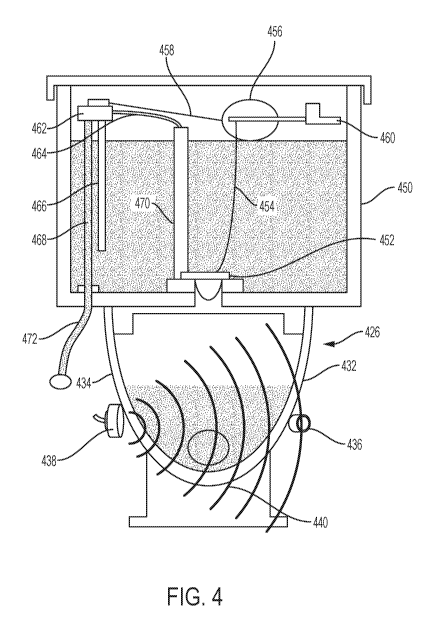
[0096] Figure 4 is a schematic illustration of a cross section of a toilet.
The toilet may
include a tank 450 and handle 460. Inside the tank 450 may be a flush valve
452, flush
valve chain 454, float ball 456, and float arm 458. The toilet may also
include an inlet valve
462, bowl refill tube 464, filter tube 466, inlet tube 468, overflow tube 470,
and supply line
472. The toilet in Figure 4 may include an alternative arrangement for the
sensor
(transducer 100 in Figure 1). The sensor may comprise a transmitter 438 and a
receiver
436. The transmitter 438 and receiver 436 may be at the same level or same
axial height on
the toilet bowl 432. The transmitter 438 and receiver 436 may be parallel,
with, for
example, the floor, the water level in the toilet, the toilet seat, or other
relative location on or
near the toilet. The transmitter 438 and receiver 436 may be piezo-ceramic
transducers. The
transmitter 438 may be located on a first side 434 of the toilet bowl 426 and
the receiver 436
may be mounted on a second side 432 of the toilet bowl 426, opposite the
transmitter 438.
As can be appreciated from Figure 4, the ultrasonic signal 440 passes through
the toilet
bowl and the toilet bowl 426 contents when traveling from the transmitter 438
to the
receiver 436. When the toilet bowl is at a state of routine water level, the
ultrasonic signal
440 traverses the toilet bowl 426 in normal state. When the toilet bowl
contents are other
than the routine water level (as described with relation to Figure 3), the
ultrasonic signal
440 may be take more or less time to traverse the toilet bowl 426. The
presences of solids
or a solid clog may absorb the ultrasonic signal (i.e., the ultrasonic signal
440 is attenuated)
and a signal may not be received by the receiver 436 or a minimal signal may
be received.
Figure 4 may include an AFE and microcontroller as previously described to
determine a
ToF measurement from the signal received at the receiver 436 and thus
determine a bowl
status.
23
CA 03028005 2018-12-14
WO 2018/009877 PCT/US2017/041214
[0097] Figure 5 is a schematic of a simple version of the system of an
embodiment of the
invention showing the interrelation of the sensor (transducer), related
circuitry, and the
microcontroller. Figure 5 depicts a schematic toilet bowl 500 where the sensor
510 is
located on a bottom, outer surface of the toilet bowl 500. The sensor 510 may
be an
ultrasonic transducer, such as a piezo-ceramic transducer, as previously
described. The
analog front end (AFE) 530 may cause the sensor 510 to resonate, thus
generating an
ultrasonic signal 550 which travels through the liquid in the toilet bowl 500.
The signal 550
reaches the target 520, which may be a barrier or separation or interface
between the fluid
and the air, and is reflected back toward the sensor 510. The sensor 510
receives the signal
550 and the AFE 530 then generates a ToF measurement which is communicated to
the
microcontroller 540.
[0098] Figure 5A is a schematic of a system according to the principles of the
present
disclosure for transmitting and receiving a signal and processing the signal
to determine a
Time of Flight measurement. The system of Figure 5A may include a sensor or
transducer
510, such as an ultrasonic transducer or piezo-ceramic transducer, as
previously described.
The sensor or transducer 510 may be electrically connected to an analog front
end (AFE)
530. The AFE 530 may initiate the transducer 510 to resonate, thus generating
a signal
550A, such as an ultrasonic signal. The signal 550A will transmit through a
first media 560
(such as, in the example of Figure 5, a liquid or water). When the signal
reaches a target
520, such as a barrier or transition between the first media 560 and a second
media 570, the
signal may be reflected back to the transducer 510 as a return signal 550B.
The target 520
may be a solid barrier or target or may be a transition between two media,
such as the first
media 560 and the second media 570. The first media 560 may be, for example, a
liquid or
water (such as is present in a toilet bowl) and the second media 570 may be,
for example, air
(such as is present above the liquid or water in a toilet bowl). The target
520 may also be
the wall of a toilet bowl; in this situation, the AFE 530 may be programmed to
ignore these
reflections and only determine a ToF measurement for signals reflected off an
object in the
toilet bowl or the liquid/air transition in the toilet bowl. When the return
signal 550B is
received by the transducer 510, the signal is communicated to the AFE 530,
which then
determines a ToF measurement from when the signal is initiated in the
transducer 510 to
when the signal is returned to the transducer 510. It can thus be appreciated
that the ToF
measurement may vary based on the media 560, 570 and the target 520 due to
ultrasonic
signals traveling at varying speeds through different media.
24
CA 03028005 2018-12-14
WO 2018/009877 PCT/US2017/041214
[0099] Figure 6 and Figure 7 show a cross section of a toilet illustrating a
situation where
the system may be used to detect and remedy a "low water" bowl status, thereby
preventing
the escape of sewer gases into the environment. Figure 6 shows a toilet bowl
626 in cross
section with water in a toilet outlet 652 and having a satisfactory water seal
644, which may
be a mechanical water seal 644 with the dimension of the mechanical water seal
being 2
inches (i.e., the vertical distance 642 ("VD") between the water surface 646
and the trap dip
648 is 2 inches). The mechanical water seal 644 prevents any sewer gases 650
from
backing up through the bowl outlet and escaping into the environment.
[00100] Figure 7 shows a cross section of a toilet where the water surface 746
in the
toilet has become so low that the VD 742 (the vertical distance between the
water surface
746 and the trap dip 748) is below zero and sewer gases 750 are egressing via
the toilet
outlet 752 and invention as, upon measurement of a "low water" level, this
information is
electronically conveyed to the microcontroller and as result an appropriate
flush volume of
water is delivered to the bowl, such volume in this instance being at least
sufficient to
restore a minimum VD for the mechanical water seal and therefore to maintain
the
mechanical water seal and prevent escape of sewer gases into the environment.
[00101] EXAMPLE 1
[00102] A small scale toilet bowl was replicated by mounting a PVC tube to a
ceramic
wall tile, as is seen in Figure 8. A piezo-ceramic sensor from STEM Inc.,
model
SMD15T21R111WL, was positioned at the bottom of the PVC tube 800 on a bottom
surface of the tile 802. The cavity of the PVC tube is filled with a volume of
water (about
1.8 kg) to achieve a first water level, "normal" 804 and a "normal" ToF
measurement is
obtained. Referencing Figure 9, when water alone is present in the cavity, the
distance
between "start" and "stop" is the Time of Flight measurement using the
calculation: Fluid
level = (TOF x Fluid Speed of Sound)/2.
[00103] In Figure 9, data from a sensor used to monitor the exemplary small
scale toilet
bowl of Figure 8 is depicted. The graph in Figure 9 is a voltage versus time
plot for the
duration of a test when the liquid is at a routine level in the toilet bowl.
The data 920
represents the raw ultrasonic signal transmitted and received by the sensor.
Data point 900
represents when the AFE sends the start pulse to the sensor and the ultrasonic
signal is
transmitted from the transducer. Data point 910 represents that the sensor has
received the
return signal or the receiver (in a transmitter/receiver sensor like Figure 4)
receives the
CA 03028005 2018-12-14
WO 2018/009877 PCT/US2017/041214
signal. The time between the start position and the stop position is recorded
and a ToF
measurement is generated. In the example, this time is approximately 60 .is
(microseconds). Thus, using the data in Figure 9, Fluid level = (601.ts x 1484
m/s)/2 =
45mm. That is, the fluid level in the bowl at the exemplary normal status is
45 mm.
[00104] Referring back to the example of Figure 8, a portion of miso paste (50
grams) is
placed in the PVC tube 800. Referencing Figure 10, a sensor signal is
transmitted and a
ToF measurement corresponding to the sensor signal is recorded. Data 1020
represents the
raw ultrasonic signal transmitted by the sensor. Data point 1000 represents
when the AFE
sends the start pulse to the sensor and the ultrasonic signal is transmitted
from the
transducer. In this example, when there are solids (e.g., miso paste) in the
cavity, there is
only a "start" because the solids attenuate (or absorb) the signal. That is,
the return signal is
not received by the sensor. Thus, the ToF measurement is the detection of the
absence of a
determinable ToF flight. A microcontroller can be programmed to make the
distinction
between a ToF of about 45mm and no determinable ToF, and associate each with a
"liquid"
status and a "solid" status, respectively.
[00105] In Figures 11A-11D, various statuses of a toilet 1100 can be seen,
according to
an embodiment. Figures 11A-11D depict a side view of a toilet 1100 with a
sensor system
1102. The sensor system 1102 may operate in a manner previously described to
communicate with a microcontroller (not depicted) to detect the status of the
toilet bowl
1104. In Figure 11A, the status may be a normal liquid level 1106 and may
correspond to
the "normal" status ToF measurement to which other statuses are compared. In
Figure 11B,
the sensor system 1102 and microcontroller may detect urine 1108 or other
light liquid in
the toilet bowl 1104. The ToF measurement may be compared to the "normal"
status (e.g.,
the ToF measurement for liquid level 1106). The microcontroller may then
actuate a valve
in the toilet 1100 to open for a specified time to perform a low-volume flush.
In Figure
11C, the sensor system 1102 and microcontroller may detect solids 1110, such
as solid
waste, in the toilet bowl 1104. The ToF measurement may be compared to the
"normal"
status (e.g., the ToF measurement for liquid level 1106). The microcontroller
may then
actuate a valve in the toilet 1100 to open for a specified time (e.g., a time
longer than the
time opened for the status of Figure 11B) to perform a full-volume flush. In
Figure 11D,
the sensor system 1102 may detect an overflow condition 1112 in the toilet
bowl 1104. The
ToF measurement may be compared to the "normal" status (e.g., the ToF
measurement for
26
CA 03028005 2018-12-14
WO 2018/009877 PCT/US2017/041214
liquid level 1106). The microcontroller may then actuate a valve in the toilet
1100 to close
until the clog 1114 or other obstruction is removed from the toilet.
[00106] As may be appreciated from the foregoing disclosure-, the system may
measure
the water level in a toilet bowl. The system may notify of an abnormal
condition requiring
user intervention. In embodiments, if the water level exceeds a predetermined
level, the
system may disable an automatic flush and notify of a potential toilet clog or
overflow
condition. In embodiments, the system may prevent or limit the water damage in
a
bathroom. The system may detect when content present in the toilet remains in
the toilet
(e.g., due to an ineffective flush) and the microcontroller may send a signal
to issue a
subsequent flush.
[00107] It will be appreciated by those skilled in the art that changes could
be made to
the embodiments described above without departing from the broad inventive
concept
thereof It is understood, therefore, that this invention is not limited to the
particular
embodiments disclosed, but it is intended to cover modifications within the
spirit and scope
of the present invention as defined by the appended claims. Although the
foregoing
description is directed to the preferred embodiments of the invention, it is
noted that other
variations and modifications will be apparent to those skilled in the art, and
may be made
without departing from the spirit or scope of the invention. Moreover,
features described in
connection with one embodiment of the invention may be used in conjunction
with other
embodiments, even if not explicitly stated above.
27