Note: Descriptions are shown in the official language in which they were submitted.
CA 03034226 2019-02-15
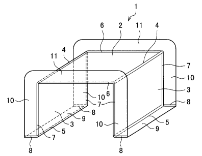
1
Description
Title of Invention
AUTOMOBILE BODY PRESS-MOLDED COMPONENT AND METHOD FOR
PRODUCING SAME
Technical Field
[0001]
The present invention relates to an automobile body press-molded component
that
can enhance the strength and the rigidity of an automobile body effectively
and a method
for producing the same. Specifically, the present invention relates to an
automobile body
press-molded component having a hat-like transverse cross-sectional shape that
includes a
top sheet, vertical walls, flanges, and ridgelines formed between the top
sheet and the
vertical walls and between the vertical walls and flanges, and a method for
producing the
.. same. The automobile body press-molded component includes outward flanges
that are
formed on at least one end portions in the extending directions of ridgelines
so as to be bent
outwardly from the vertical walls with respect to a cross section of the
component. The
automobile body press-molded component is a press-molded component formed of a
metal
sheet in which outward flanges leading to the vertical walls (hereinafter,
referred to as
"vertical wall flanges") and flanges (hereinafter, referred to as "floor
flanges") are formed
continuously and the radius of curvature of a corner portion of the vertical
wall adjacent to
the outward flange and the floor flange (hereinafter, referred to as a
vertical wall angle R)
is small. A component "formed of a metal sheet" may be a component having
steel sheet
nature or a component made of an aluminum sheet, as an example.
Background Art
[0002]
An automobile body is usually produced such that a large number of molded
panels are joined together by resistance spot welding while edge portions of
panels are
.. superimposed on each other and thus box bodies are formed, and reinforcing
members or
strengthening members are joined to important places of the box bodies by
resistance spot
welding. A member thus produced is referred to as an automobile body
structural member.
CA 03034226 2019-02-15
2
Examples of such an automobile body structural member include a floor cross
member, a
locker (a side sill), a belt line, etc. In the following description, a floor
cross member is
taken as an example of the automobile body structural member.
[0003]
The floor cross member has a press-molded, substantially hat-like transverse
cross-sectional shape composed of a top sheet, two ridgelines leading to the
top sheet
(hereinafter, referred to as "upper ridgelines"), two vertical walls
individually leading to
the two upper ridgelines, two ridgelines individually leading to the two
vertical walls
(hereinafter, referred to as "lower ridgelines"), and two floor flanges
individually leading
to the two lower ridgelines, for example. Outward flanges that are bent
outwardly with
respect to a cross section of the component are formed on end portions in the
extending
directions of the upper ridgelines and the lower ridgelines in a main body
that is formed of
a steel sheet and has the above transverse cross-sectional shape, the outward
flanges are
superimposed on a side sill inner, and then assembly is performed by
resistance spot
welding, arc welding, or the like. The floor cross member is an important
automobile
body structural member contributing to the rigidity of the car body and the
suppression of
the crushing of the cabin at the time of a lateral collision. Hence, until
now, a large number
of inventions that enhance the strength of a car body by reexamining the
shapes of members
and the structures of bonding portions between members and a large number of
inventions
regarding methods for producing members have been disclosed.
[0004]
Patent Literature 1 discloses an invention in which the performance of a
member
is enhanced by continuously forming a top sheet, vertical walls, and outward
flanges
adjacent to upper ridgelines that are provided in an end portion in the
longitudinal direction
of a press-molded product having a hat-like cross section. Patent Literature 2
discloses
an invention in which the bonding strength between a side sill and a floor
cross member is
enhanced by providing an opening in a side surface of a side sill inner and
welding together
a sill inner reinforce and the floor cross member placed in the interior of
the side sill.
Patent Literature 3 discloses an invention in which the bonding strength
between a side sill
and a floor cross member is enhanced by opening a side sill inner without
enlarging the
transverse cross section and providing a plurality of welds for bonding with
the floor cross
member.
CA 03034226 2019-02-15
3
Citation List
Patent Literature
[0005]
Patent Literature 1: JP 2015-74354A
Patent Literature 2: JP 2996031B
Patent Literature 3: JP H2-141372A
Patent Literature 4: JP 5569661B
Patent Literature 5: JP 2560416B
Patent Literature 6: JP 2554768B
Patent Literature 7: JP H7-112219A
Patent Literature 8: JP H4-118118A
Summary of Invention
Technical Problem
[0006]
Patent Literatures 1 to 3 are what are invented for the purpose of improving
lateral
collision safety. However, none of these patent literatures has an invention
focusing
attention on the magnitude of the vertical wall angle R. For example, Patent
Literature 1
shows, in its drawings, a member having a large vertical wall angle R in which
the portion
between a vertical wall flange and a floor flange is formed in a gently
continuous manner.
On the other hand, in Patent Literature 2, the vertical wall angle R is
relatively small unlike
what is shown in the drawings of Patent Literature 1. In Patent Literature 3,
the situation
of the vicinity of the vertical wall angle R is unclear. Further, none of
these patent
Literatures describes the dimensions of the vertical wall angle R in detail.
Thus, little
attention has been focused on and no detailed studies have been conducted on
the influence
of the vertical wall angle R on the performance of the member.
CA 03034226 2019-02-15
4
Solution to Problem
[0007]
The present inventors conducted extensive studies in order to solve the issue
mentioned above in view of such issues of the conventional technologies and
have obtained
findings A to D listed below, and have completed the present invention.
(A) The length of a cross-sectional line in an end portion of a member is
increased by
reducing the magnitude (the radius of curvature) of the vertical wall angle R.
Thus, the
performance (load capacity properties) of the member is improved in an axial
crushing
deformation mode, such as one inputted to a floor cross member at the time of
a lateral
collision.
(B) Specifically in (A), it is preferable that a dimension of the vertical
wall angle R be set
to less than or equal to 13% relative to the length of the cross-sectional
line in an end portion
of the member.
(C) The areas of the vertical wall flange and the floor flange increase in
association with
the reduction of the vertical wall angle R. Thus, the number of welds of spot
welding or
the length of the weld of arc welding or laser welding can be increased at the
time of
bonding to another member, and an improvement in the performance of the car
body, such
as the efficiency of bonding between members or rigidity, is achieved.
(D) A gap that may occur during bonding to another member can be filled up by
the
reduction of the vertical wall angle R. An improvement in the performance of
the car
body, such as the efficiency of bonding between members or rigidity, is
achieved.
(E) The performance of the member can be further enhanced by, in addition to
reducing the
vertical wall angle R, continuously forming the top sheet, the vertical walls,
and the
outward flanges adjacent to the upper ridgelines that are provided in an end
portion in the
longitudinal direction of the press-molded product of a hat-like cross
section.
[0008]
The present invention is as listed below.
(1)
A member including:
a top sheet;
two facing vertical walls provided on both sides of the top sheet via upper
ridgelines;
CA 03034226 2019-02-15
a top sheet flange extending on an outside of the member via a top sheet
ridgeline
of the top sheet existing on a side of an end portion of the member;
two vertical wall flanges each extending on the outside of the member via a
vertical wall ridgeline of the vertical wall extending on the side of the end
portion of the
5 member; and
two floor flanges each of which is adjacent to the vertical wall flange and
extends
on the outside of the member via a lower ridgeline that extends on an end
portion of the
vertical wall different from an end portion of the vertical wall on the side
of the end portion
of the member,
in which the vertical wall flange and the floor flange adjacent to an end
portion of
the vertical wall flange are continuous with each other, and
in the end portion of the member, a sum total ER of radii of curvature of
angles of
the vertical walls each between the lower ridgeline and the vertical wall
ridgeline and a
sum total EL of widths of the top sheet and the vertical walls in the end
portion of the
member have a relation of ER/EL < 0.13.
(2)
The member according to claim 1,
in which the radius of curvature of the angle of the vertical wall between the
lower
ridgeline and the vertical wall ridgeline is less than or equal to 20 mm.
(3)
The member according to claim 1 or 2,
in which the top sheet flange and the vertical wall flange are continuous.
(4)
The member according to any one of claims 1 to 3,
in which the vertical wall is a triangle, and
the floor flange serves also as the vertical wall flange.
(5)
A method, based on press molding, for producing a press-molded product, the
method being for producing the member according to any one of claims 1 to 4,
CA 03034226 2019-02-15
6
the method including:
a first step of molding, in a shrink flange manner, at least parts of floor
flanges and
parts of vertical wall flanges continuous to the floor flanges, in at least
two places of a
blank; and
a second step of, following the first step, molding, in a stretch flange
manner, a
top sheet flange and remaining parts of the vertical wall flanges continuous
to the top sheet
flange, in at least two places between the at least two places of the blank in
the first step.
[0009]
An object of the present invention is to provide a member like the floor cross
member of FIG. 1. However, the member dealt with by the present invention is
not limited
to a floor cross member, and the vertical wall is not limited to a quadrangle
either. For
example, as shown in FIG. 2, a press-molded product in which the vertical wall
is a triangle
is possible.
[0010]
However, when it is attempted to produce the member by press molding, the
portion between the vertical wall flange and the floor flange forms a shrink
flange portion,
and therefore wrinkles resulting from surplus wall thicknesses occur. For
example, Patent
Literature 4 describes a method for producing a member disclosed in Patent
Literature 1;
however, when a shrink flange portion between a vertical wall flange and a
floor flange is
press-molded using Patent Literature 4, wrinkles resulting from surplus wall
thicknesses
occur because tension cannot be applied to the steel sheet during press
molding.
Consequently, it has been necessary that the occurrence of wrinkles be reduced
by
providing a notch between the vertical wall flange and the floor flange or by
setting the
vertical wall angle R as large as, for example, 30 mm. Thus, even when the
floor cross
member is joined to a side sill inner via the vertical wall flanges as
described above, the
load capacity properties at the time of axial crushing upon a collision or the
like is relatively
low because the notch mentioned above or a gap caused by the large vertical
wall angle R
exists unavoidably in the vicinity of a joint portion between the floor cross
member and the
side sill. Hence, when forming an outward flange, it is necessary to perform
the molding
of a shrink flange portion while suppressing the occurrence of wrinkles in the
shrink flange
portion. Until now, a large number of inventions in which a shrink flange
portion is press-
molded without wrinkles have been disclosed. For example, Patent Literature 5
discloses
CA 03034226 2019-02-15
7
an invention in which the occurrence of wrinkles is prevented by providing a
specific shape
to a shrink flange portion in square cup drawing molding, Patent Literatures 6
and 7
disclose inventions in which a shape for absorbing an excessive line length in
a shrink
flange portion is provided to a roof panel having an opening for a sunroof,
and Patent
.. Literature 8 discloses an invention in which the occurrence of wrinkles is
suppressed by
performing molding while applying pressing force to a shrink flange portion by
using a
cam structure.
[0011]
However, for the invention disclosed by Patent Literature 5, although it can
be
.. implemented when it does not influence the external appearance or the
performance of the
product, joining becomes difficult and the load transfer capacity at the time
of collision
deformation is reduced when the specific shape is provided to a place that is
to be connected
to another component (a side sill) like in, for example, a floor cross member.
[0012]
The inventions disclosed by Patent Literatures 6 and 7 absorb a surplus line
length,
which is a cause of wrinkles and surplus wall thicknesses, by means of a
surplus wall
thickness shape set in advance. Hence, the inventions disclosed by Patent
Literatures 6
and 7 cannot be implemented when the surplus wall thickness portion
constitutes an
obstacle to the spot welding of another part, not to mention when resistance
spot welding
is performed in this advance wall thickness portion.
[0013]
Further, for the invention disclosed by Patent Literature 8, although out-of-
plane
deformation associated with buckling can be suppressed with reliability, there
is no change
to a place where shrinkage deformation concentrates and the sheet thickness
increases.
Hence, mold contact is severe in a place of an excessive wall thickness
increase, and the
durability of the mold and accordingly productivity are reduced.
[0014]
Thus, in the conventional technologies, it has been impossible to perform
press
molding without the occurrence of wrinkles between a vertical wall flange and
a floor
flange, and hence a reduction in load transfer characteristics at the time of
axial crushing
upon a collision or the like has been unavoidable.
CA 03034226 2019-02-15
8
[0015]
The present inventors conducted extensive studies in order to solve the issue
mentioned above and have obtained findings (A) to (C) listed below, and have
completed
the present invention.
(A) In a first step, shrink flange molding is performed on a blank under
arbitrary constraint
conditions and linkage portions each between a vertical wall flange and a
floor flange are
molded, and an intermediate molded product is obtained.
(B) In a second step, press molding is performed on the intermediate molded
product in
which the linkage portions each between a vertical wall flange and a floor
flange are molded,
and a press-molded component having a desired transverse cross-sectional shape
that
includes a top sheet, vertical walls, and flanges is obtained.
(C) A shape in which a top sheet, vertical walls, and outward flanges adjacent
to upper
ridgelines are continuous can be created by using inner pad molding described
later in the
second step.
[0016]
The present invention is as listed below.
(1) A method for producing a press-molded component including a first step of
performing
press molding on a blank to form the lower flange linkage portions mentioned
above in a
shrink flange manner and thereby producing an intermediate molded product
having at least
the lower flange linkage portions mentioned above and a second step of
performing press
molding on the intermediate molded product to produce the press-molded
component
mentioned above having the transverse cross section mentioned above.
Advantageous Effects of Invention
[0017]
The present invention can provide a member that exhibits high load capacity in
a
joint portion when the member is used by being joined to another member and
has received
a collision load. Further, the present invention can provide a method for
producing the
member by press molding.
CA 03034226 2019-02-15
9
Brief Description of Drawings
[0018]
[FIG. 1] FIG. 1 is an explanatory diagram of an end portion of a member.
[FIG. 2] FIG. 2 is an explanatory diagram of a different member.
[FIG. 3] FIG. 3 is an explanatory diagram showing a member according to the
present
invention.
[FIG. 4] FIG. 4 is an explanatory diagram showing another member according to
the
present invention.
[FIG. 5] FIG. 5 is an explanatory diagram of a corner portion of a member
having high
strength.
[FIG. 6] FIG. 6 is an explanatory diagram of a corner portion of a member
having low
strength.
[FIG. 7] FIG. 7(a) and FIG. 7(b) are graphs showing results of an analysis by
computer
simulation of influence of a radius of curvature R (mm) of a corner portion
between a lower
ridgeline and a vertical wall ridgeline on axial crushing characteristics in
an event in which
an impact load is applied in an extending direction of upper ridgelines and
thereby axial
crushing is brought about in a state where a member is joined to another
member via
outward flanges.
[FIG. 8] FIG. 8 is an explanatory diagram showing an analysis result.
[FIG. 9] FIG. 9 is an explanatory diagram showing an analysis result.
[FIG. 10] FIG. 10 is an explanatory diagram showing an analysis result.
[FIG. 11] FIG. 11 is an explanatory diagram showing an analysis result.
[FIG. 12] FIG. 12 is an explanatory diagram of an impact test.
[FIG. 13] FIG. 13 is an explanatory diagram of a production process based on
press molding.
[FIG. 14] FIG. 14 is an explanatory diagram showing a production apparatus 20.
[FIG. 15] FIG. 15 is an explanatory diagram showing placement of a blank
before a start
of molding in the production apparatus 20.
[FIG. 16] FIG. 16 is an explanatory diagram showing a situation of a molding
bottom dead
center of the production apparatus 20.
[FIG. 17] FIG. 17 is an explanatory diagram showing a production apparatus 30.
[FIG. 18] FIG. 18 is an explanatory diagram showing a blank before a start of
preliminary
molding in the production apparatus 30.
CA 03034226 2019-02-15
[FIG. 19] FIG. 19 is an explanatory diagram showing a blank after an end of
preliminary
molding by the production apparatus 30.
[FIG. 201 FIG. 20 is an explanatory diagram showing a production apparatus 40.
[FIG. 21] FIG. 21 is an explanatory diagram showing placement of a preliminary
molded
5 product before a start of molding in the production apparatus 40.
[FIG. 22] FIG. 22 is an explanatory diagram showing a situation of a molding
bottom dead
center of the production apparatus 40.
[FIG. 23] FIG. 23 is an explanatory diagram showing a configuration of a
production
apparatus of an example of a production apparatus 50.
10 [FIG. 24] FIG. 24 is an explanatory diagram showing a placement
situation of an
intermediate molded product in the production apparatus 50.
[FIG. 25] FIG. 25 is an explanatory diagram showing a situation of a molding
bottom dead
center in the production apparatus 50.
[FIG. 26] FIG. 26 is an explanatory diagram showing a configuration of a
production
apparatus of another example of a production apparatus 60.
[FIG. 27] FIG. 27 is an explanatory diagram showing a placement situation of
an
intermediate molded product in the production apparatus 60.
[FIG. 28] FIG. 28 is an explanatory diagram showing a situation of a ridgeline
pad in the
production apparatus 60 at a time of holding.
[FIG. 29] FIG. 29 is an explanatory diagram showing a situation of a molding
bottom dead
center in the production apparatus 60.
Description of Embodiments
[0019]
Hereinafter, (a) preferred embodiment(s) of the present invention will be
described
in detail with reference to the appended drawings. Note that, in this
specification and the
appended drawings, structural elements that have substantially the same
function and
structure are denoted with the same reference numerals, and repeated
explanation of these
structural elements is omitted.
[0020]
CA 03034226 2019-02-15
11
1. Member according to present invention
(1) Shape of member
FIG. 3 is an explanatory diagram showing a member 1 according to the present
invention, and FIG. 4 is an explanatory diagram showing another member 12
according to
the present invention. In the drawings, the single line represents an edge of
the member,
the double line a ridgeline, and the dotted line a place hidden behind the
member.
[0021]
The member 1 of FIG. 3 is a member formed of a high-tensile steel sheet in
which
the tensile strength is more than or equal to 440 MPa, preferably more than or
equal to 590
MPa, and more preferably more than or equal to 980 MPa, and the sheet
thickness is more
than or equal to 0.7 mm and less than or equal to 2.3 mm.
[0022]
The member 1 of FIG. 3 has a hat-like transverse cross section that includes a
top
sheet 2, two upper ridgelines 4, two facing vertical walls 3, two lower
ridgelines 5, and two
floor flanges 9.
[0023]
Each of the upper ridgelines 4 exists between the top sheet 2 and a vertical
wall 3.
Each of the lower ridgelines 5 exists between a vertical wall 3 and a floor
flange 9.
[0024]
The member 1 includes outward flanges on at least one end portions of the
upper
ridgelines 4 via ridgelines. A top sheet flange 11 extends on the outside of
the member
via a top sheet ridgeline 6 extending between end portions of the upper
ridgelines 4. Each
of vertical wall flanges 10 extends on the outside of the member via a
vertical wall ridgeline
7 that is adjacent to the top sheet ridgeline 6 and extends on an end portion
of a vertical
wall 3. The top sheet flange 11 and the vertical wall flanges 10 are
continuous, and the
top sheet flange 11 and the vertical wall flanges 10 constitute an outward
flange.
[0025]
Also an end portion of the vertical wall flange 10 and the floor flange 9 are
continuous via a flange ridgeline 8; and an end portion of the vertical wall
ridgeline 7, an
end portion of the lower ridgeline 5, and an end portion of the flange
ridgeline 8 are linked
together at one point.
CA 03034226 2019-02-15
12
[0026]
The top sheet flange 11 and the vertical wall flanges 10 may not be continuous
on
end portions of the upper ridgelines 4. However, the performance of the member
is
improved when the top sheet flange 11 and the vertical wall flanges 10 are
continuous on
end portions of the upper ridgelines 4. In the case where the top sheet flange
11 and the
vertical wall flanges 10 are made continuous, the degree of difficulty in
molding is
increased, and hence attention is required to the selection of the material,
the width of the
flange, etc.
[0027]
The point of difference between the member 12 of FIG. 4 and the member 1 of
FIG. 3 is that, in the member 12, the vertical wall 3 is a triangle, and the
upper ridgeline 4
and an end portion of the lower ridgeline 5 are linked together at another end
portion of the
upper ridgeline 4 where there is no vertical wall flange 10. As a result, the
top sheet flange
11 and the floor flange 9 are continuous at this other end portion. From
another point of
view, since the vertical wall 3 is a triangle, both functions of the floor
flange 9 and the
vertical wall flange 10 are present at this other end portion. In the present
embodiment,
even in the case where the vertical wall 3 is a triangle, also a configuration
in which the top
sheet flange 11 is not continuous with the floor flange 9 or the vertical wall
flange 10 is
permitted, like in the case of FIG. 3 where the vertical wall is a quadrangle.
"The vertical
wall 3 being a triangle" means that the vertical wall 3 includes three corner
portions, i.e., a
corner portion where the upper ridgeline 4 and the vertical wall ridgeline 7
cross, a corner
portion where the vertical wall ridgeline 7 and the lower ridgeline 5 cross,
and a corner
portion where the upper ridgeline 4 and the lower ridgeline 5 cross. Shapes
slightly
deviated from a triangle composed of three sides of straight lines are
permitted, such as a
.. shape in which a corner portion is round or a ridgeline runs in a zigzag
fashion.
[0028]
FIG. 5 shows a case where the strength of the B portion of FIG. 1 is high.
FIG. 6
shows a case where the strength of the B portion of FIG. 1 is low. Each of the
cross
sections of the ridgelines is bent between double lines in the drawings. An
area where the
radius of curvature of the cross section of a ridgeline is small is indicated
by an arrow.
When FIG. 5 and FIG. 6 are compared, it can be seen that the radius of
curvature R of a
corner portion of the vertical wall 3 between the lower ridgeline 5 and the
vertical wall
CA 03034226 2019-02-15
13
ridgeline 7 is increased if end portions of the lower ridgeline 5 and the
vertical wall
ridgeline 7 are dull (the radii of curvature of the bending of the cross
sections of the
ridgelines are large). If end portions of the lower ridgeline 5 and the
vertical wall ridgeline
7 are dull, that is, the radii of curvature R are large, the strengths of the
end portion of the
lower ridgeline 7 and the end portion of the vertical wall ridgeline 5 are
reduced, and the
vertical wall flange 10 and the floor flange 9 cannot be joined to another
member up to the
vicinity of the flange ridgeline 8; consequently, the load capacity and the
rigidity of the
member are reduced.
[0029]
In the member of the present invention, the sum total ER of the radii of
curvature
of corner portions of the vertical walls 3 each between the lower ridgeline 5
and the vertical
wall ridgeline 7 (vertical wall angles R) and the sum total a of the lengths
of the top sheet
ridgeline 6 of the top sheet 2 and the vertical wall ridgelines 7 of the
vertical walls 3 in an
end portion of the member have the relation of ZRJEL < 0.13. The sum total of
the widths
of the top sheet 2 and the vertical walls 3 in an end portion of the member is
the length on
the assumption that each of the angles of the vertical walls 3 and the top
sheet 2 in the end
portion is a pin angle (the radius of curvature being 0).
[0030]
When it is envisaged that the member of the present invention is used as an
automotive member, the a of the automotive member is approximately 300 mm, and
accordingly the radius of curvature of the angle of the vertical wall 3
between the lower
ridgeline 5 and the vertical wall ridgeline 7 (the vertical wall angle R) is
approximately less
than or equal to 20 mm.
[0031]
(2) Effects of member
FIG. 7(a) and FIG. 7(b) are graphs showing results of an analysis of the axial
crushing characteristics of the member 1 by computer simulation. The analysis
was
performed with a model in which an impact load in the direction in which the
upper
ridgelines 4 extend was applied in a state where the member 1 was joined to
another
member (a side sill inner) via outward flanges (the vertical wall flanges 10
and the top sheet
flange 11). FIG. 7(a) and FIG. 7(b) show the influence of the radius of
curvature R of a
corner portion of the vertical wall 3 between the lower ridgeline 5 and the
vertical wall
CA 03034226 2019-02-15
14
ridgeline 7 (the vertical wall angle R) (mm) on axial crushing characteristics
at the time of
axial crushing. FIG. 7(a) shows relationships between the crushing stroke in
the
extending direction of the upper ridgelines 4 and the load in the cases where
the radius of
curvature R is 2 mm and 20 mm. In FIG. 7(a), the solid line shows the case
where the
radius of curvature R is 2 mm, and the broken line shows the case where the
radius of
curvature R is 20 mm. FIG. 7(b) shows a relationship between the radius of
curvature R
and the maximum load (load capacity). In the cross-sectional shape of the
member 1, the
sum total a of the widths of the top sheet 2 and the vertical walls 3 in an
end portion of
the member is 300 mm. The material was simulated using a steel sheet with a
tensile
strength of 980 MPa and a sheet thickness of 1.2 mm. Since attention is
focused only on
the influence of the radius of curvature R of the corner portion of the
vertical wall 3 between
the lower ridgeline 5 and the vertical wall ridgeline 7 (the vertical wall
angle R), each of
the other angles of the top sheet 2 and the vertical walls 3 is simulated
using a pin angle
(the radius of curvature of the angle being 0).
[0032]
As shown by the graph of FIG. 7(a), it can be seen that, when the radius of
curvature R is smaller, the load particularly in an early period of the
collision is larger;
further, as shown by the graph of FIG. 7(b), the maximum load (load capacity)
becomes
higher as the radius of curvature R becomes smaller. Thus, the member 1 can
improve
load transfer characteristics (collision performance) at the time of axial
crushing upon a
collision or the like as the radius of curvature R of the corner portion of
the vertical wall 3
between the lower ridgeline 5 and the vertical wall ridgeline 7 (the vertical
wall angle R)
(mm) becomes smaller.
[0033]
FIG. 8 shows a comparison of load capacity (the maximum load) when the height
of the vertical wall 3 and the width of the top sheet 2 of the member 1 of
FIG. 3 were altered.
In both cases, the sum total EL of the widths of the top sheet 2 and the
vertical walls 3 in
an end portion of the member is 300 mm. FIG. 8 is the result of an analysis in
which a
case where an impact load was inputted to a member 1 formed of a material with
a tensile
strength of 980 MPa and a sheet thickness of 1.2 mm in the direction in which
the upper
ridgelines 4 extend was simulated. For ER/EL on the horizontal axis of the
graph of FIG.
8, the radius of curvature R of the corner portion of the vertical wall 3
between the vertical
CA 03034226 2019-02-15
wall ridgeline 7 and the lower ridgeline 5 (the vertical wall angle R) was
altered. The
lengths of the vertical wall ridgeline 7 and the top sheet ridgeline 6 were
altered while the
sum total EL of the lengths of the vertical wall ridgelines 7 and the top
sheet ridgeline 6
was kept fixed, but a change was not seen in terms of the load capacity being
improved in
5 ER/EL < 0.13.
[0034]
FIG. 9 shows a comparison of load capacity (the maximum load) when the length
of the cross-sectional line was altered without changing the ratio between the
lengths of the
vertical wall ridgeline 7 and the top sheet ridgeline 6 of the member 1 of
FIG. 3. In FIG.
10 .. 9, the height of the vertical wall 3 and the width of the top sheet 2
are equal. The
conditions of the analysis of FIG. 9 are the same as those of FIG. 8. The
length of the
cross-sectional line was altered without changing the ratio between the width
of the top
sheet 2 and the width of the vertical wall 3 in an end portion of the member,
but a change
was not seen in terms of the load capacity being improved in ER/EL < 0.13.
15 [0035]
FIG. 10 shows the result of an analysis in which the radii of curvature R of
the
corner portions of the vertical walls 3 each between the vertical wall
ridgeline 7 and the
lower ridgeline 5 of the member 1 of FIG. 3 (the vertical wall angles R) were
altered. In
the model of the analysis of FIG. 10, the radii of curvature R of the corner
portions of the
vertical walls 3 each between the vertical wall ridgeline 7 and the lower
ridgeline 5 (the
vertical wall angles R) were altered while the sum total a of the widths of
the top sheet 2
and the vertical walls 3 in an end portion of the member 1 was kept to be 300
mm and
ER/EL was kept to be 0.13. That is, the radius of curvature of one vertical
wall angle R
was altered while the sum of the one vertical wall angle R and the other
vertical wall angle
R was kept fixed. The conditions of the analysis of FIG. 10 are the same as
those of FIG.
8. The horizontal axis of the graph of FIG. 10 represents the radius of
curvature R of the
corner portion of a vertical wall 3 between a vertical wall ridgeline 7 and a
lower ridgeline
5 (a vertical wall angle R). When ER/EL is fixed, a large change was not seen
in load
capacity even when the radii of curvature of the angles of the vertical walls
3 were changed.
CA 03034226 2019-02-15
16
[0036]
From the results of FIG. 8, FIG. 9, and FIG. 10, it can be seen that the
member 1
has high load capacity (maximum load) in the case where ER/EL < 0.13,
regardless of the
transverse cross-sectional shape of the member 1.
[0037]
FIG. 11 shows a comparison of the maximum load when the width of the vertical
wall 3 and the width of the top sheet 2 in an end portion of the member 12 of
FIG. 4 were
altered. In both cases, the length of the cross-sectional line L is 300 mm.
The material
of the member 12 is the same as the material of the analysis of FIG. 8. In the
analysis, a
case where, as shown in FIG. 12, the member 12 was placed in a hat-shaped
material and
an impact load was inputted from the top sheet surface of the hat-shaped
material was
simulated. Thus, a result in which the load capacity was improved in ER/EL <
0.13 was
obtained similarly to FIG. 8.
[0038]
For the member 12 of FIG. 4, the analysis of FIG. 12 was performed also on
models corresponding to FIG. 9 and FIG. 10; then, results similar to the
results of the
member 1 were obtained. That is, in the member I of FIG. 3 and the member 12
of FIG.
4, high load capacity (maximum load) is exhibited in the case where ER/EL <
0.13,
regardless of the shape of the flange 11 (the width of the vertical wall 3,
the width of the
top sheet 2, or the vertical wall angle R in an end portion of the member).
[0039]
Although the shapes are different, the member 1 of FIG. 3 and the member 12 of
FIG. 4 have a common feature of exhibiting high load capacity (maximum load)
in the case
where ER/EL < 0.13.
[0040]
2. Production apparatus and production method for members 1 and 12
In the case where a member of the present invention (the member 1 or the
member
12) is produced by press molding, the production may be performed by two
steps. A first
step molds, in a shrink flange manner, the floor flanges 9 and parts of the
vertical wall
flanges 10 that are continuous to the respective floor flanges 9 via the
respective flange
ridgelines 8. A second step is performed following the first step, and molds
the top sheet
flange 11 and the remaining parts of the vertical wall flanges 10 that were
not molded in
CA 03034226 2019-02-15
17
the first step and that are continuous to the top sheet flange 11. FIG. 13
shows a sequence
of steps in the case where a member of the present invention is produced by
press molding.
In the first step, an intermediate molded product 27 is produced from a blank
26 or 34.
Examples of the production method include Case 1-1 where a production
apparatus 20 is
used and Case 1-2 where a production apparatus 30 is used to produce a
preliminary molded
product 35 and a production apparatus 40 is used to produce an intermediate
molded
product 27 from the preliminary molded product 35, and either method is
possible. In the
second step, the member 1 or the member 12 is produced from the intermediate
molded
product 27. Examples of the production method include Casse 2-1 where a
production
apparatus 50 is used and Case 2-2 where a production apparatus 60 is used, and
either
method is possible.
[0041]
(1) Case 1-1 (first step; production apparatus 20)
An apparatus 20 performs press molding on a blank 26 to form, in a shrink
flange
manner, the floor flanges 9 and parts of the vertical wall flanges 10 that are
continuous to
the respective floor flanges 9 via the respective flange ridgelines 8, and
produces an
intermediate molded product 27.
[0042]
FIG. 14 is an explanatory diagram showing the production apparatus 20. FIG.
15 is an explanatory diagram showing the placement of the blank 26 before the
start of
molding in the production apparatus 20. FIG. 16 is an explanatory diagram
showing a
situation of the molding bottom dead center based on the production apparatus
20, in which
a description of a punch 21 is omitted for easier viewing of the drawing.
[0043]
As shown in FIG. 14, the production apparatus 20 includes a punch 21,
protrusion-
provided dies 22, and a pad 23. The protrusion-provided dies 22 are arranged
facing the
punch 21. The protrusion-provided die 22 integrally includes a bending tool 25
having a
protrusion portion 24. The bending tool 25 may be a separate body from the die
22.
[0044]
In the production apparatus 20, as shown in FIGS. 14 to 16, the protrusion
portions
24 press portions of the blank 26 corresponding to the flange ridgelines 8,
earlier than
portions of the bending tools 25 other than the protrusion portions 24 press,
and thereby
CA 03034226 2019-02-15
18
perform stretch flange molding to cause the places to be molded into the
flange ridgelines
8 to undergo shear deformation. Thus, the production apparatus 20 molds the
blank 26
into an intermediate molded product 27 including the flange ridgelines 8. A
part 28 of the
intermediate molded product 27 supposed to be molded into the top sheet flange
11 may
not be molded by the production apparatus 20.
[0045]
Reasons why the occurrence of wrinkles is suppressed in the flange ridgeline 8
and its surroundings by this method will now be described.
[0046]
By using the protrusion portion 24 to precedingly press at least part of the
portion
to be molded into the flange ridgeline 8, a difference in deformation speed
occurs between
the precedingly pressed region and other regions. Hence, factors for a shear
deformation
field in the portion to be molded into the flange ridgeline 8 can be enhanced
with reliability.
[0047]
In other words, this is because, by using the bending tool 25 including the
protrusion portion 24, a deformation factor of the flange ridgeline 8 is
changed from a factor
for a shrink flange deformation field (the strain ratio 13 (E2/e1) < -1; a
wall thickness
increase) to a factor for a shear deformation field (the strain ratio 13
(62/61) -1; no sheet
thickness change). In addition, surplus wall thicknesses that may occur in the
flange
ridgeline 8 are pushed out to the surroundings and are dispersed. By these,
wrinkles that
may occur in the flange ridgeline 8 and its surroundings and excessive sheet
thickness
increases can be suppressed effectively.
[0048]
The pressing by the protrusion portion 24 is preferably performed on the
position
of the center in the perimeter direction of the flange ridgeline 8, but may be
performed on
a position deviated from the position of the center in the perimeter direction
of the flange
ridgeline 8.
[0049]
The height h (mm) of the protrusion portion 24 provided on the surface of the
bending tool 25 preferably satisfies Formula (1) below with respect to the
radius of
curvature rf (mm) of the bending of the flange ridgeline 8. This is because,
if the height
h of the protrusion portion 24 is less than (0.5 x rf), the effect of forming
a shear
CA 03034226 2019-02-15
19
deformation field in the flange ridgeline 8 to suppress the increase in sheet
thickness will
be small; and if the height h is more than (3.5 x rf), damage to the
protrusion portion 24
may be caused.
0.5 x rf < h < 3.5 x rf ........ (1)
[0050]
Thus, in the first step, the production apparatus 20 uses the punch 21, the
protrusion-provided dies 22, and the pad 23 to mold the blank 26 into the
intermediate
molded product 27, through a process in which the protrusion portions 24 press
portions
corresponding to the flange ridgelines 8 earlier than portions other than the
protrusion
portions 24 press.
[0051]
(2) Case 1-2 (first step; production apparatus 30 and production apparatus 40)
FIG. 17 is an explanatory diagram showing a production apparatus 30 used in
Case
1-2. FIG. 18 is an explanatory diagram showing a blank 34 before the start of
preliminary
molding in the production apparatus 30. FIG. 19 is an explanatory diagram
showing a
preliminary molded product 35 produced by being subjected to preliminary
molding by the
production apparatus 30. FIG. 17 to 19 illustrate a half of the production
apparatus 30.
In FIG. 18 and FIG. 19 of the production apparatus 30, a description of a die
31 is omitted
for easier viewing of the drawings.
[0052]
The production apparatus 30 includes dies 31, pads 32, and punches 33 arranged
facing the dies 31 and the pads 32; and performs press molding on a blank 34
to mold
portions corresponding to the floor flanges 9, and produces a preliminary
molded product
35.
[0053]
FIG. 20 is an explanatory diagram showing a production apparatus 40. FIG. 21
is an explanatory diagram showing the placement of the preliminary molded
product 35
before the start of molding in the production apparatus 40. FIG. 22 is an
explanatory
diagram showing a situation of the molding bottom dead center based on the
production
apparatus 40. In FIGS. 21 and 22, a description of a punch 36 is omitted for
easier viewing
of the drawings. The diagram at the upper right of FIG. 21 shows the punch 36
with the
broken line.
CA 03034226 2019-02-15
[0054]
The production apparatus 40 molds the preliminary molded product 35 into an
intermediate molded product 27. Tools included in the production apparatus 40
are a
punch 36, dies 37 arranged facing the punch 36, out-of-plane deformation
suppression tools
5 38 that are arranged in the vicinities of portions corresponding to the
flange ridgelines 8 so
as to face the punch 36, and a pad 39. At the start of molding, using these
tools, portions
of the preliminary molded product 35 corresponding to the flange ridgelines 8
are molded
while the preliminary molded product 35 is pressed and restrained by the punch
36 and the
pad 39; and an intermediate molded product 27 is molded.
10 [0055]
During press molding, portions of the preliminary molded product 35
corresponding to the floor flanges 9 are restrained by the out-of-plane
deformation
suppression tools 38 and side surfaces of the punch 36, and thereby the out-of-
plane
deformation of these portions during molding is suppressed.
15 [0056]
The out-of-plane deformation suppression tool 38 is placed while a gap
obtained
by, as necessary, adding a clearance to the sheet thickness of the preliminary
molded
product 35 is provided from a side surface of the punch 36.
[0057]
20 Specifically, the out-of-plane deformation suppression tool 38 is
preferably placed
facing a surface of a portion of the preliminary molded product 35 that
corresponds to the
floor flange 9 during press molding, so as to have a gap of a prescribed
distance x in the
sheet thickness direction of the preliminary molded product 35. As a result,
the out-of-
plane deformation of the portion corresponding to the floor flange 9 can be
suppressed with
reliability. The prescribed distance x is prescribed by Formula (2): 1.00 x t
< x < 1.40 x t
(provided that t represents the sheet thickness (mm) of the preliminary molded
product 35
and x represents the distance (mm)).
In addition, the sheet thickness in the flange ridgeline 8 and its surrounding
region
where the sheet thickness is increased from the sheet thickness before press
molding of the
preliminary molded product 35 is set not to exceed, even at the maximum, 1.5
times the
sheet thickness before press molding mentioned above. To suppress mold galling
during
molding, it is preferable to provide a minute gap. When the sheet thickness is
thin, the
CA 03034226 2019-02-15
21
occurrence of out-of-plane deformation is significant; thus, it is preferable
that the portion
between the out-of-plane deformation suppression tool 38 and the punch 36 have
a gap of
a prescribed distance x in the sheet thickness direction of the preliminary
molded product
35. The prescribed distance x is prescribed by Formula (3): 1.03 x t < x <
1.35 x t
(provided that t represents the sheet thickness (mm) of the preliminary molded
product 35
and x represents the distance (mm)).
The out-of-plane deformation suppression tool 38 may be provided at the die
37,
but is not limited to this example. It is sufficient for the out-of-plane
deformation
suppression tool 38 to be able to restrain a portion of the preliminary molded
product 35
corresponding to the floor flange 9. Hence, the installation position of the
out-of-plane
deformation suppression tool 38 is not limited to a specific position.
Further, the out-of-
plane deformation suppression tool 38 may be placed as a lower mold, not
attached to an
upper mold.
[0058]
Thus, the production apparatus 30 uses the pads 32, the dies 31, and the
punches
33 to perform press molding on a blank 26. Thereby, a preliminary molded
product 35 in
which portions corresponding to the floor flanges 9 are molded is produced.
Next, the
production apparatus 40 uses the punch 36, the dies 37, the out-of-plane
deformation
suppression tools 38, and the pad 39 to mold portions of the preliminary
molded product
35 corresponding to the flange ridgelines 8, and thereby molds an intermediate
molded
product 27.
Although not shown, in the first step, press molding may be performed while a
blank 26 or 34 is pressed by, together with the dies 22 or 31, blank holders
arranged facing
the dies 22 or 31.
.. [0059]
(3) Case 2-1 (second step; production apparatus 50)
FIG. 23 is an explanatory diagram showing the configuration of a production
apparatus 50. FIG. 24 is an explanatory diagram showing a placement situation
of the
intermediate molded product 27 in the production apparatus 50. FIG. 25 is an
explanatory
diagram showing a situation of the molding bottom dead center in the
production apparatus
50. In FIG. 25, a description of a die 53 is omitted.
CA 03034226 2019-02-15
22
As shown in FIGS. 23 to 25, the production apparatus 50 includes a punch 51
including an inner pad 52 that is placed so as to be able to freely enter and
exit a punch top
portion 51a and a die 53 placed facing the punch 51 and supporting a die pad
54.
In the second step, the second apparatus 50 uses the inner pad 52 and the die
pad
54 to start press molding while separating the intermediate molded product 27
from the
punch top portion 51a. In more detail, an intermediate molded product 27 or 40
is
sandwiched by the inner pad 52 and the die pad 54 in a state where the inner
pad 52 is kept
protruding. Next, the die 53 is moved downward, the die 53 pushes the die pad
54, the
intermediate molded product 27 or 40 and the inner pad 52 are pushed by the
die pad 54,
and molding progresses. At the molding bottom dead center, the inner pad 52
enters a
state of being housed in the punch 51. Thereby, portions of the vertical wall
flanges 10 in
the member 1 or 12 that were not molded in the first step, the top sheet
flange 11, and the
upper ridgelines 4 can be molded.
[0060]
(4) Case 2-2 (second step; production apparatus 60)
FIG. 26 is an explanatory diagram showing the configuration of a production
apparatus 60. FIG. 27 is an explanatory diagram showing a placement situation
of the
intermediate molded product 27 in the production apparatus 60. FIG. 28 is an
explanatory
diagram showing a situation of a ridgeline pad 63 in the production apparatus
60 at the time
of holding. FIG. 29 is an explanatory diagram showing a situation of the
molding bottom
dead center in the production apparatus 60. In FIG. 29, dies 62 are omitted.
[0061]
As shown in FIGS. 26 to 29, the second apparatus 60 includes a punch 61, dies
62
placed facing the punch 61, and a ridgeline pad 63 that pushes portions to be
molded into
places in each of which an end portion of the top sheet ridgeline 6, an end
portion of the
upper ridgeline 4, and an end portion of the vertical wall ridgeline 7 are
linked together.
[0062]
In the second step, the production apparatus 60 uses the ridgeline pad 63 to
perform press molding. The ridgeline pad 63 pushes portions of the
intermediate molded
product 27 that are to be molded into places in each of which an end portion
of the top sheet
ridgeline 6, an end portion of the upper ridgeline 4, and an end portion of
the vertical wall
ridgeline 7 are linked together. In this way, end portions of the upper
ridgelines 4, the top
CA 03034226 2019-02-15
23
sheet ridgeline 6, and the top sheet flange 11 are molded. Next, the dies 62
are moved
toward the punch 61, and the upper ridgelines 4 are molded in the intermediate
molded
product 27. Thus, the member 1 or 12 is produced. Thereby, portions of the
vertical
wall flanges 10 in the member 1 or 12 that were not molded in the first step,
the top sheet
flange 11, and the upper ridgelines 4 can be molded.
Reference Signs List
[0063]
1 member
2 top sheet
3 vertical wall
4 upper ridgeline
5 lower ridgeline
6 top sheet ridgeline
7 vertical wall ridgeline
8 flange ridgeline
9 floor flange
10 vertical wall flange
11 top sheet flange
12 member (a vertical wall being a triangle)
26 expansion blank
27 intermediate molded product