Note: Descriptions are shown in the official language in which they were submitted.
CA 03128090 2021-07-27
WO 2020/160439 PCT/US2020/016161
SYSTEM AND METHOD FOR INTRAOPERATIVE, NON-INVASIVE NERVE
IDENTIFICATION USING SNAPSHOT POLARIMETRY
CROSS-REFERENCE TO RELATED APPLICATIONS
100011 The present application claims priority to U.S. Provisional Application
No.
62/800,185, filed February 1, 2019, the teaching of which is incorporated by
reference herein
in its entirety for all purposes.
BACKGROUND
100021 A nerve is defined as a bundle of fibers composed of neurons. It
connects the body
parts and organs to the central nervous system and transmits sensory and motor
information
via electrical and chemical signals. Neuropathy or nerve damage can present as
various
symptoms depending on the location and type of nerves that are affected. Among
them,
motor nerve injury occurring during surgery would be disastrous. Facial nerve
injury during
head and neck surgery results in facial paralysis including asymmetry of
facial expression,
difficulty eating or drinking, loss of blinking control, and drooping of the
mouth on the
affected side. Damage of the recurrent laryngeal nerve (RLN) during
thyroidectomy could
induce paresis or palsy of the vocal cord. Injury of the RLN of both sides
cause airway
obstruction, and might result in the requirement for a tracheostomy. Pelvic
nerve injury after
radical rectal cancer surgery can cause urinary dysfunction (-27%) or sexual
dysfunction
(11-55%).
100031 At present, nerve identification and avoidance of iatrogenic trauma
relies heavily on
the surgeon's knowledge of anatomy and experience of delicate dissection
techniques.
Despite best efforts to preserve nerves, accidental nerve injuries are
sometimes inevitable.
Reports show that 17% of the total number of reported nerve injuries occur
unexpectedly
1
CA 03128090 2021-07-27
WO 2020/160439 PCT/US2020/016161
during surgical interventions, which indicates a substantial number worldwide.
This is mainly
due to the difficulty in differentiating nerves from the surrounding tissues
such as fat,
lymphatic tissues, small blood vessels, and other connective tissues, which
have similar
colors. In the case of tumors, nerve tissue is embedded within the tumor
tissue. In particular,
smaller branches of nerves are extremely hard to identify intraoperatively by
the naked eye
because of the complexity of their distributions and orientations.
[0004] The foregoing "Background" description is for the purpose of generally
presenting
the context of the disclosure. Work of the inventor, to the extent it is
described in this
background section, as well as aspects of the description which may not
otherwise qualify as
prior art at the time of filing, are neither expressly or impliedly admitted
as prior art against
the present invention.
BRIEF DESCRIPTION OF THE DRAWINGS
[0005] A more complete appreciation of the disclosure and many of the
attendant advantages
thereof will be readily obtained as the same becomes better understood by
reference to the
following detailed description when considered in connection with the
accompanying
drawings, wherein:
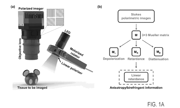
100061 FIG. IA is a schematic that shows a mechanism of the practical
polarimetric imaging
method. (a) System schematic of the overall platform. (b) Calculation flow to
derive the
birefringence map from the output of the linear polarizer array camera. Mesh
rectangle in (a)
illustrates the positions and orientations of the polarization filters for
each 4-pixel block;
[0007] FIG. 1B is a schematic of the overall platform for real-time snapshot
imaging. A
trigger command may be sent to concurrently activate the illumination system
on and initiate
camera data acquisition. Therefore, the switching of three different linearly
polarized
2
CA 03128090 2021-07-27
WO 2020/160439 PCT/US2020/016161
illuminations can be synchronized with camera acquisition in a single cycle.
In this way, real-
time snapshot imaging and birefringence map processing can be realized;
100081 FIG. 2 is a schematic that shows a performance evaluation of the
imaging method
described herein on phantoms. (a) Expected (lower left) and measured (right)
Mueller matrix
from imaging a horizontally oriented linear polarizer; a monochromatic image
of the
polarizer is also shown (upper left). (b) Expected (lower left) and measured
(right) Mueller
matrix from imaging a vertically oriented linear polarizer; a monochromatic
image of the
polarizer is also shown (upper left). (c) Monochromatic image of birefringent
and normal
plastic films on a tissue-mimicking pad and (d) birefringence map of the films
acquired using
the method described herein;
100091 FIG. 3 is a schematic that shows RGB images (left) and birefringence
maps (right) of
four different regions that include nerves in anesthetized rats. Nerves were
carefully pre-
identified before polarimetric imaging was performed (green arrows, overlaid
on both the
RGB and birefringence images). Results from different-sized femoral nerves are
shown in (a)
and (b). (c) The main branches of the phrenic nerves are shown in (c), and (d)
shows
subsidiary branches of the same;
10010j FIG. 4A is a schematic that shows RGB images and birefringence maps of
four nerve
regions in pigs in situ. Nerves were carefully pre-identified before
polarimetric imaging
(green arrows, on both the RGB and birefringence images (a) RGB image and (b)
birefringence map of a region with a branch of the superior laryngeal nerve
within it. (c)
RGB image and (d) birefringence map of small peripheral nerve branches
surrounded mostly
by fat tissue. Red diamonds in (a) and (b) indicate fat tissues;
[0011] FIG. 4B is a schematic that shows RGB images and birefringence maps of
(a)
superior laryngeal nerve (SLN) in a swine neck and (b) femoral nerves in a
right leg of a
swine in vivo;
3
CA 03128090 2021-07-27
WO 2020/160439 PCT/US2020/016161
100121 FIG. 5 is a flowchart for a nerve identification process according to
one example; and
100131 FIG. 6 is an exemplary block diagram of a computer according to one
example.
DETAILED DESCRIPTION
10014[ Referring now to the drawings, wherein like reference numerals
designate identical or
corresponding parts throughout several views, the following description
relates to a system, a
device, and associated methodology for intraoperative non-invasive nerve
identification. A
full field birefringence map is obtained and used to highlight nerve
structures in an operative
field.
[0015] Electrical nerve stimulation has been used to identify nerves. However,
even blunt
dissection may lead to severe nerve injury, and the use of an electrical probe
is invasive and
can create distractions during surgical procedures. Fluorescent markers can be
a good
alternative to highlight nerve structures but no suitable dyes are as yet
clinically available,
and there are concerns about procedural complexity and the potential toxicity
of the use of
fluorescent markers intraoperatively. Significant advances in nerve
identification have been
demonstrated using optical coherence tomography (OCT) imaging; however,
although OCT
allows high-resolution deep-penetration 3D mapping, the images have a small
field-of-view,
and it requires a bulky sophisticated optical system, making it of limited
practical use during
operations.
[0016] Polarimetry has been widely used in biomedical applications and this
technique holds
great potential to address the unmet challenge of intraoperative nerve
imaging. Nerves
possess intrinsic anisotropic structures within the myelin and demonstrate
strong
birefringence, which points to a straightforward way to characterize and
visualize them.
Capitalizing on analysing the polarization of detected photons, poIarimetfic
imaging allows
direct measurement of birefringence without any invasive procedures. There
have been
4
CA 03128090 2021-07-27
WO 2020/160439 PCT/US2020/016161
numerous promising methods using polarimetric imaging for tissue
characterization, but the
published studies have thus far been limited to ex vivo conditions,
potentially due to system
complexity and other restrictions such as motion artifacts.
[0017] Conventionally, polarimetry requires multiple repeated data acquisition
steps and
processing to calculate Mueller and Stokes matrices. Thanks to recent
technological
advances, a compact camera with four sets of linear polarizer arrays is
commercially
available, permitting fast, high-definition polarimetric imaging via simple
snapshots.
Exploiting this camera, we have developed a practical polarimetric imaging
method that
allows a fast Mueller polarimetric analysis and can process birefringence maps
over the entire
field of view (FONT) in near real-time. The method was intraoperatively tested
by identifying
various nerves in rodents in vivo and in swine in situ. The results show that
sciatic and
phrenic nerves in rats can be clearly identified by exhibiting their intrinsic
bands-of-Fontana
structures. We also demonstrate that in pigs the platform could differentiate
superior
laryngeal nerves (SLN) and peripheral nerves from surrounding tissues by
mapping the
birefringence. With future improvements in processing speed, this practical
polarimetric
imaging method could potentially provide a useful tool for intraoperative
nerve visualization.
100181 Figure 1A(a) depicts the system setup for Mueller polarimetric imaging
using a linear
polarizer array camera. The polarimetric camera is used as a polarization
state analyser
(PSA), and a simple polarization state generator (PSG) is also applied using a
motorized
linear polarizer. The polarimetric camera consists of a filter with a
pixelated linear polarizer
array in front of the sensor. As shown in the dash-outlined rectangle in Fig.
1A(a), the sensor
and filter were carefully aligned so that every four adjacent pixels of the
sensor is precisely
overlaid by four different tiny linear polarizers, of which the angles of the
axes are 0 , 450
,
90 , and 135 degrees, respectively. The first three elements of a Stokes
vector, which
represent the entirety of the polarization state except the circularity, can
be directly measured.
CA 03128090 2021-07-27
WO 2020/160439 PCT/US2020/016161
Although complete Stokes vectors could become measurable by adding a
controllable
retarder, it would increase the complexity of the system and thus make it less
practical. In
consequence, we can only resolve a 3 x 3 Mueller matrix for each set of 2 x 2
pixels, but this
is nonetheless sufficient to reveal important polarization information about
the tissues,
including their birefringence. Moreover, reducing the Mueller matrices also
significantly
reduces the requirements for the PSG, which consists of a low-power LED, a
motorized
rotator, and a linear polarizer, in our system. In an embodiment, the PSG may
include one or
more low-power LEDs and one or more linear polarizers. The PSG generates
polarized-light
illumination, with linear polarization angles of 00, 450, and 900,
respectively, to derive the 3
x 3 Mueller matrices for each set of 2 x 2 pixels. A wavelength of the
illumination source
may be selected to ensure good penetration capacity and to minimize
interference with vision
of a surgeon. In an embodiment, the wavelength of the illumination source may
be between
400 nm and 2500 nm. In an example, the wavelength of the illumination source
may be 730
nm. Three snapshots of the polarimetric camera are needed for each of the
three different
polarized illuminations. After the pixel-wise Mueller matrices are derived, an
established
polar decomposition method can be applied to calculate the phase retardance
between the fast
and slow axes of the birefringence (Fig. 1A(b)), which should be positive
overall in nerves
due to their fibrillar structure.
100191 Fig. 1B provides further details regarding the system setup. In
particular, this figure
additionally illustrates a circuitry that permits real-time imaging by
triggering signals to an
illumination system and a camera, synchronously. The illumination light source
includes
coaxial, three different linearly polarized filters with predetermined angles.
A circuitry can
send the trigger signals to control the timing of taking snapshot images from
the camera and
the switching of polarized light sources. In this manner, the real-time
acquisition is achieved
and it eliminates motion artefacts that may be introduced by the subject.
There are several
6
CA 03128090 2021-07-27
WO 2020/160439 PCT/US2020/016161
ways to achieve the switching of the polarizations. One way is to use one
light source and one
polarimetric filter, for example, a linear polarizer, and rotate the filter
before taking each
snapshot at a fast rate. Another way is to use multiple light sources that are
co-axially aligned
and equipped with three linearly polarized filters in front of each light
source. The angles of
the linearly polarized filters are fixed and predetermined corresponding to
the desired angles
of 00, 45 , and 900, respectively. Therefore, the rapid switching of the
linearly polarized
illumination can be achieved by triggering the polarized light sources at
predetermined speed.
100201 See Methods for more technical details about the system setup and
calculation flow.
100211 We used phantoms to examine the feasibility of the system and test its
performance;
first of all, the goal was to check that only minor birefringence was induced
by the optical
components in the optical setup. We used a linear polarizer (LPVISE100-A,
Thorlabs,
U.S.A.), with extinction ratio ¨18000:1 at 730 nm, placed on top of white
paper as the object.
We compared the derived Mueller matrices using the polarimetric camera and the
theoretical
matrices for the polarizer oriented at approximately 0 and 90 (Fig. 2(a) and
2(b)). The
comparison of these two results indicates good agreement between the measured
and
theoretically expected values of the elements in the Mueller matrices. The
minor mismatches
could perhaps result from an imperfect installation of the setup or some small
diattenuations
within it. The overall good performance validates the feasibility of this
polarimetry design.
100221 To further test the birefringence detection performance of the system,
we used
conventional plastic and birefringent films to mimic non-birefringent and
birefringent tissues
respectively. The two pieces of these films are very similar in dimensions,
with thicknesses
for both of ¨70 gm. We placed the films on a commercial soft-tissue mimicking
pad (3-
DMED, U.S.A.) and employed the polarimetric imaging method described herein to
visualize
their differences. The fast axis of the birefringent film is parallel to one
of its edges. As
shown in Fig. 2(c) and 2(d), although in the monochromatic images the two
pieces of film
7
CA 03128090 2021-07-27
WO 2020/160439 PCT/US2020/016161
look very similar to each other, a significant difference in their
birefringence properties can
be detected. This experimental result indicates that the polarimetric imaging
method
described herein is capable of mapping birefringence with adequate
sensitivity.
[0023] As a first test of the nerve identification method, we carried out in
vivo experiments
on anesthetized rats. We first focused on nerves which are easily recognized
by experienced
surgeons and animal handlers. Conventional RGB photographs were also taken at
the same
time, for reference and comparison. After the confirmation of stable
anaesthesia, we carefully
exposed the femoral nerve¨a part of the sciatic nerve, and a peripheral nerve
with motor
neurons¨with the inguinal ligaments. Polarimetric imaging was then performed.
A high-
magnification zoom lens was used for imaging so that the FOV and magnification
could be
conveniently adjusted; its working distance was approximately 22 cm for all
the tests. Strong
positive birefringence can be detected from both nerves and smooth muscle
(Fig. 3(a) and
3(b)), as the smooth muscle also consists of massive fibrillar structures.
Nevertheless, the
bands of Fontana, which is a feature unique to peripheral nerves, were clearly
revealed by the
birefringence map. The detection of bands of Fontana can therefore be used as
a strong
indicator of the location of a nerve, isolating the nerve structure from any
muscle-induced
birefringence background signals. By applying this strategy, we were able to
easily identify
all the femoral nerves using the birefringence maps.
[0024] We also performed polarimetric imaging on parts of the phrenic nerves
using a larger
FOV after surgical dissections on the necks of the rats were performed to
expose them.
Similar phenomena were observed. Although strong birefringence was also
detected here
from the surrounding smooth muscles, we were easily able to identify the
nerves by
visualizing the bands of Fontana (Fig. 3(c)). The birefringence map also
demonstrates that
nerves that are significantly separated in space can be identified
simultaneously. To test the
imaging performance with higher magnifications for smaller nerves, we traced
the phrenic
8
CA 03128090 2021-07-27
WO 2020/160439 PCT/US2020/016161
nerves to their subsidiary branches near the neck and collected a polarimetric
image (Fig.
3(d)) with a small FOV. The results show that two sections of the small
subsidiary branches
of the nerves are detectable by their birefringence. Bands of Fontana in the
upper branch can
be clearly observed, while they are unclear in the other branch; this could be
because the
epineurium is thicker for certain parts of nerves, so that it becomes more
difficult to reveal
the fine structure beneath it.
100251 Polarimetric images were collected from small SLN branches in swine in
situ. We
first carefully dissected the pigs to expose the major branches of the SLN on
the neck. From
the major branches, we traced the nerve to identify downstream branches of the
SLN. Then
we acquired the birefringence map of this region. Pronounced birefringence was
observed
from the major nerve branch in the map (Fig. 4A(b)). In contrast, the tissue
indicated by the
red diamond-shaped marker in Fig. 4A(a) and (b), which could be composed of
fat, has
overall very low or negative birefringence values. Although the nerve and the
other tissue
have very similar colours in terms of RGB values as shown in Fig. 4A(a), our
imaging
method was able to differentiate them with high contrast. We also tested this
imaging strategy
on the porcine pelvis, in which there are many small branches of peripheral
nerves
underneath fat tissue. We cautiously identified two small branches of the
nerves based on
anatomical knowledge and the experience of our surgeons, and then imaged them
using the
polarimetry system. Similar to our previous result, even though the nerves and
fat look very
similar in the RGB images (Fig. 4A(c)), our imaging and analysis system was
able to
distinguish the nerves from the surrounding tissues (Fig. 4A(d)).
[00261 With reference now to Fig. 4B, a live animal study was performed with
consideration
to animal motion, including breathing. Figure 4B illustrates representative
results that show
RGB images and birefringence maps of superior laryngeal nerve (SLN) in a swine
neck and
femoral nerves in a right leg of a swine in vivo. Fig. 4B(a) shows that the
SLN identified by
9
CA 03128090 2021-07-27
WO 2020/160439 PCT/US2020/016161
an expert surgeon (green arrow) during dissection and imaged on both the RGB
and
birefringence map in real-time. Fig. 4B(b) shows that the femoral nerves are
identified by an
expert surgeon (green arrows) and imaged on both the RGB and birefringence map
in real-
time without motion artifacts. The results clearly show that the SLN from
surrounding
thyroid tissue and the femoral nerves in a swine can be highlighted by the
real-time
birefringence map acquired from Fig. 1B system.
100271 Nerve damage during surgery is unfortunately still a significant cause
of morbidity
and loss of decease of life. One of the reasons for this is the difficultly in
isolating nerve
structures from surrounding tissues by the naked eye. This work demonstrates
the capability
of snapshot polarimetry to intraoperatively distinguish nerves from
surrounding tissues.
Encouraged by the availability of a fast and compact polarimetric camera, we
developed a
practical imaging method for intraoperative nerve identification. Mapping of
birefringence
was achieved via three snapshots of the camera to highlight the fibrillar
structures of nerves
as contrast against the surrounding tissue. To this end, we have made the
important first step
of proving this concept and demonstrating the feasibility of our simple system
setup, which
can be easily adapted for surgery. Unlike other techniques that have been used
to identify
nerves, snapshot polarimetry is non-invasive, less interruptive with no risk
of nerve damage
than neuromonitoring device, which is clinically available but invasive and
takes more times
with interruption of the surgical workflow. Potential clinical applications
will include
identification of facial nerves during head and neck surgery, differentiation
of RLN during
thyroidectomy and patent ductus arteriosus (PDA) ligation, and visualization
of pelvic nerve
during pelvic organ surgery, where nerves are commonly surrounding by blood,
fat and other
connection tissues.
100281 Future developments in the fast switching of polarized illumination and
in multi-
modality imaging could further increase acquisition speeds and reduce
interference from
CA 03128090 2021-07-27
WO 2020/160439 PCT/US2020/016161
unwanted birefringent tissues To minimize image-contrast interference from
smooth
muscles, an alternative could he to utilize another imaging modality, such as
hyperspectral
imaging, to separate them from nerves via their reflectance spectrum.
Quantitative analysis of
birefringence in the surgical field could also help to reduce the
interference, as the retardance
of nerves could be quantitatively different from others. Considering its easy
mechanism and
the promising performance in our study, this novel method holds great
potential for real-time
non-invasive and convenient nerve visualization. In other implementation,
neuromonitoring
in vivo to further characterize the sensitivity and specificity of the system
may be used.
100291 Methods
100301 Setup of the platform
100311 The practical imaging platform (Fig. 1A(a)) employs a newly released
CMOS linear
polarizer array camera (BFS-U3-51S5P-C, FLIR, U.S.A.). The camera can provide
a
resolution of 2448 x 2048 with a maximum frame rate of 75 frames/s. It
consists of a
monochromatic polarized sensor in which each individual pixel has its own
polarizing filter,
oriented to 00, 450, 90*, or 135 and arranged in repeating two-by-two-pixel
blocks of the
same, as shown by the dash-outlined rectangle in Fig. 1A(a). Each Stokes
vector needs to be
calculated based on the detected intensities of the four pixels, thus the
resolution of the
birefringence map is 1224 x 1024. A high-magnification lens (Zoom 7000,
NAVITAR,
U.S.A.) is attached to the camera for imaging. For the illumination, a 730-nm
LED (M730L4,
Thorlabs, U.S.A.) is combined with a linear polarizer (LpvisEi 00-A, Thorlabs,
U.S.A.) to
generate polarized input light. As indicated above, the illumination may be
provided by one
or more light sources and one or more linear polarizers, the one or more light
sources having
adjustable wavelengths between 400 Tun and 2500 nm. The linear polarizer is
mounted on a
motorized rotator (PRM1Z8, Thorlabs, U.S.A.) to control the polarization.
Though it can be
appreciated that other rates of rotation may be appropriate pursuant to
requirements of a
11
CA 03128090 2021-07-27
WO 2020/160439 PCT/US2020/016161
given application, the rotator for each study herein was operated to rotate at
a predetermined
rate of 45 per second. All the components are mounted on an aluminium bread
board, which
is fixed on a rigid steel arm (MG61033, Noga, Israel) for intraoperative use.
To operate the
system and run the algorithm to derive the birefringence maps, a Python
program was
developed to control the camera and motorized rotator, and to perform imaging
processing on
a connected laptop (OMEN 15, HP, U.S.A.). The entire procedure to acquire one
birefringence image required about 10 s, which included -6 s for rotating the
polarizer and -4
s for calculation.
[0032] Derivation of the Mueller matrix and extraction of phase retardance
[0033] Given the character of the polarizer array, the Stokes vector S for
each 4-pixel block
can be calculated directly, based on its definition as:
H + V
[0034] s= H -V ,
F + F-
100351 where H, V, F + and F- are the intensities acquired from the pixels for
which the
orientations of the polarizers are 0 , 45 , 90 , and 135 respectively. Since
we can only
determine three elements of S, the Mueller matrix M is transformed into a 3 x
3 matrix, and
for each block we can write
[0036] MS in = Sou t,
[0037] where Sin and Sout are the Stokes vectors of the illumination and
detected light. Three
different input polarization states are used, which are selected to be H, V,
and F+ . An
expression for M can then be derived:
1 1 1 11
[0038] M = [S outl 5out2 Sout3] 1 0 - 1 .
0 1 0
[0039] S
- outl, 5out2, and 5out3 represent the three respectively acquired Stokes
vectors when
H, V. and F + are used as the polarizations of the illuminating light.
12
CA 03128090 2021-07-27
WO 2020/160439 PCT/US2020/016161
[0040] After the Mueller matrix is obtained, a polar decomposition method can
be applied so
that M can be decomposed into a sequence of three solvable matrix factors,
[0041] M =MAMRMD,
[0042] where MA, MR, and MD represent the depolarization, retardance, and
diattenuation
parts of M respectively. MR can be derived, and the phase retardance 8 between
the fast and
slow axes of the birefringence can be determined using the elements of MR:
[0043] cos (6) = 4(itl R(2,2) + R(3,3))2 + R(2,3) ¨ M R(3,2))2 ¨ 1,
[0044] in which MR(x,y) denotes the element in xth column and yth row. In our
study,
cos (8) is used as the retardance value for the construction of the
birefringence maps.
[0045] Animal experiment protocols
[0046] For in vivo studies on rats, male and female 250-350 g Sprague-Dawley
rats (ri = 2)
from Charles River Laboratories (Wilmington, Massachusetts, U.S.A.) were used
for this
experiment. A 3-min inhalation of 4% Isoflurane was used for sedation and
restraint.
Anaesthesia was maintained using intramuscular injections of Xylazine (2
mg/kg) and
Ketamine (75 mg/kg). All procedures were performed at the animal research
facility under
institutional animal care and use committee under approved protocol (IACUC
#30597). After
ensuring sterile conditions, femoral nerve and phrenic nerves were carefully
dissected and
exposed at their junctions with the inguinal ligament and clavicle level,
respectively. Both
nerves were imaged using a snapshot camera in vivo.
[0047] For the in situ studies on swine, female Yorkshire 10-kg pigs (n = 2)
from Archer
Farms (Darling, Maryland, U.S.A.) were used. The pigs were sedated by
intramuscular
injection of xylazine-ketamine anaesthetic and a 3-min inhalation of 4%
Isoflurane was used
and maintained for anaesthesia. After ensuring sterile conditions, the skin
was cut from the
lower jaw tip to the caudal throat and, together with the subcutaneous fat
tissue (separated,
distinctly light white adipose tissue), moved laterally. The ventral portion
of the superficial
13
CA 03128090 2021-07-27
WO 2020/160439 PCT/US2020/016161
neck muscle was exposed. RLN and SLN were dissected and targeted for the
imaging. Small
branches of peripheral nerves inside fat tissues around skin were exposed and
the data were
collected for nerve differentiation from surrounding fat tissues. The
ventilation was paused
for snapshot imaging and euthanized by administering Beuthanasia (1 ml per
4.5kg of body
weight) through ear vein following our approved protocol (1ACUC #30591)
strictly. We
confirmed the death by checking for respirations and heart tones.
100481 FIG. 5 is a flowchart for a nerve identification process 500 according
to one example.
At S502, imaging data of a target area illuminated via the illumination system
described
herein and captured via the camera described herein are obtained.
100491 At S504, the imaging data are processed using a processor to obtain a
birefringence
map. At S506, the birefringence map of the target area including indicia of a
nerve structure
is output.
100501 The processor may be in the camera, in the illumination system, or
implemented in
circuitry of a display. The processor may also be a computer or a server
(e.g., a cloud server)
connected to the system via a network.
100511 The network 102 is any network that allows the computer, camera,
illumination
system, display, and/or third party device to communicate information with
each other.
Suitable networks can include or interface with any one or more of a local
intranet, a PAN
(Personal Area Network), a LAN (Local Area Network), a WAN (Wide Area
Network), a
MAN (Metropolitan Area Network), a VPN (Virtual Private Network), or a SAN
(storage
area network). Furthermore, communications may also include links to any of a
variety of
wireless networks, including WAP (Wireless Application Protocol), GPRS
(General Packet
Radio Service), GSM (Global system for Mobile Communication), CDMA (Code
Division
Multiple Access) or TDMA (Time Division Multiple Access), cellular phone
networks, GPS
14
CA 03128090 2021-07-27
WO 2020/160439 PCT/US2020/016161
(Global Positioning System), CDPD (Cellular digit packet data), Bluetooth
radio, or an IEEE
802.11 based radio frequency.
[0052] The features of the present disclosure provide a multitude of
improvements in the
field of medical imaging. In particular, a snapshot polarimetry system is
described as a
potential real-time, non-invasive surgical vision tool for guiding surgeons
during surgery to
recognize the unidentifiable nerve tissues with situational awareness. The
imaging technique
described herein can provide such information to surgeons intraoperatively
with minimal
interruption of the surgical workflow. We demonstrated the feasibility of
intraoperative nerve
identification with excellent contrast through in vivo animal studies both in
rats and pigs,
which offers the possibility of truly non-invasive imaging in clinical
settings. It holds a great
promise for improving surgical outcomes and reducing rates of iatrogenic
injuries.
[0053] In one implementation, the functions and processes described herein may
be
implemented by a computer 626. Next, a hardware description of the computer
626
according to exemplary embodiments is described with reference to FIG.6. In
FIG. 6, the
computer 626 includes a CPU 600 which performs the processes described herein.
The
process data and instructions may be stored in memory 602. These processes and
instructions
may also be stored on a storage medium disk 604 such as a hard drive (HDD) or
portable
storage medium or may be stored remotely. Further, the claimed advancements
are not
limited by the form of the computer-readable media on which the instructions
of the inventive
process are stored. For example, the instructions may be stored on CDs, DVDs,
in FLASH
memory, RAM, ROM, PROM, EPROM, EEPROM, hard disk or any other information
processing device with which the computer 626 communicates, such as a server
or computer.
[0054] Further, the claimed advancements may be provided as a utility
application,
background daemon, or component of an operating system, or combination
thereof, executing
in conjunction with CPU 900 and an operating system such as Microsoft Windows
,
CA 03128090 2021-07-27
WO 2020/160439 PCT/US2020/016161
UNIX , Oracle Solaris, LINUX , Apple macOSO and other systems known to those
skilled in the art.
[0055] In order to achieve the computer 626, the hardware elements may be
realized by
various circuitry elements, known to those skilled in the art. For example,
CPU 600 may be a
Xenon or Core processor from Intel Corporation of America or an Opteron
processor
from AMID of America, or may be other processor types that would be recognized
by one of
ordinary skill in the art. Alternatively, the CPU 600 may be implemented on an
FPGA,
ASIC, PLD or using discrete logic circuits, as one of ordinary skill in the
art would
recognize. Further, CPU 600 may be implemented as multiple processors
cooperatively
working in parallel to perform the instructions of the inventive processes
described above.
[0056] The computer 626 in FIG. 6 also includes a network controller 606, such
as an Intel
Ethernet PRO network interface card from Intel Corporation of America, for
interfacing with
network 624. As can be appreciated, the network 624 can be a public network,
such as the
Internet, or a private network such as LAN or WAN network, or any combination
thereof and
can also include PSTN or ISDN sub-networks. The network 624 can also be wired,
such as
an Ethernet network, or can be wireless such as a cellular network including
EDGE, 3G and
4G wireless cellular systems. The wireless network can also be WiFie,
Bluetooth , or any
other wireless form of communication that is known.
[0057] The computer 626 further includes a display controller 608, such as a
NVIDIA
GeForce GTX or Quadro graphics adaptor from NVIDIA Corporation of America
for
interfacing with display 610, such as a Hewlett Packard HPL2445w LCD monitor.
A
general purpose I/0 interface 612 interfaces with a keyboard and/or mouse 614
as well as an
optional touch screen panel 616 on or separate from display 610. General
purpose I/O
interface also connects to a variety of peripherals 618 including printers and
scanners, such as
an OfficeJet or DeskJete from Hewlett Packard .
16
CA 03128090 2021-07-27
WO 2020/160439 PCT/US2020/016161
10058l The general purpose storage controller 620 connects the storage medium
disk 604
with communication bus 622, which may be an ISA, EISA, VESA, PCI, or similar,
for
interconnecting all of the components of the computer 626. A description of
the general
features and functionality of the display 610, keyboard and/or mouse 614, as
well as the
display controller 608, storage controller 620, network controller 606, and
general purpose
I/0 interface 612 is omitted herein for brevity as these features are known.
100591 Obviously, numerous modifications and variations are possible in light
of the above
teachings It is therefore to be understood that within the scope of the
appended claims, the
invention may be practiced otherwise than as specifically described herein.
[0060] Embodiments of the present disclosure may also be as set forth in the
following
parentheti cal s.
[0061] (1) A system for nerve identification, the system comprising a camera
including a
sensor, and a filter having a linear polarizer array, an illumination system
configured to
illuminate a target area with polarized light illumination, the polarized
light illumination
having at least one predetermined polarization angle, the illumination system
including one
more light sources, and one or more polarizer filters, and a processor
configured to process
imaging data obtained from the camera, and output a birefringence map of the
target area
including indicia of a nerve structure.
[0062] (2) The system of (1), wherein the filter and the sensor are aligned
and every
predetermined number of pixels of the sensor overlays a predetermined number
of linear
polarizers of the linear polarizer array.
[00631 (3) The system of either (1) or (2), wherein the predetermined number
of pixels is
four and angles of axes of the linear polarizers are 00, 45 , 900, and 1350
.
100641 (4) The system of any one of (1) to (3), wherein the one or more light
sources are low
power light emitting diodes.
17
CA 03128090 2021-07-27
WO 2020/160439 PCT/US2020/016161
[0065] (5) The system of any one of (1) to (4), wherein each of the one or
more polarizer
filters is a linear polarizer coupled to a motorized rotator, the motorized
rotator being
configured to rotate the linear polarizer at a predetermined rate.
[00661 (6) The system of any one of (1) to (5), wherein the camera is
configured to obtain at
least three shots of the target area, each associated with a position of the
linear polarizer.
[0067] (7) The system of any one of (1) to (6), wherein the predetermined rate
of rotation of
the linear polarizer is at least 45 per second.
[0068] (8) The system of any one of (1) to (7), wherein each of the one or
more polarizer
filters is a linear polarizer with a fixed polarization angle.
[0069] (9) The system of any one of (1) to (8), wherein the at least one
predetermined
polarization angle is one or more of 0 , 45 , and 90 .
[0070] (10) The system of any one of (1) to (9), wherein the one or more light
sources are
configured to emit light having an adjustable wavelength.
[0071] (11) The system of any one of (1) to (10), wherein the one or more
light sources are
configured to emit light having a wavelength between 400 nm and 2500 nm.
[0072] (12) The system of any one of (1) to (11), wherein the processor is
further configured
to determine a Mueller matrix associated with each predetermined polarization
angle based
on the imaging data, determine a phase retardance based on the Mueller matrix,
and
determine the birefringence map based on the phase retardance
[0073] (13) The system of any one of (1) to (12), wherein the system is
configured for
intraoperative, non-invasive surgery and/or semi-or fully autonomous surgery.
[0074] (14) The system of any one of (1) to (13), wherein the processor is
configured to
perform real-time processing of the imaging data received by the camera.
[0075] (15) The system of any one of (1) to (14), wherein a view of the camera
has an
adjustable spatial resolution.
18
CA 03128090 2021-07-27
WO 2020/160439 PCT/US2020/016161
[0076] (16) A method for nerve identification using a system that includes a
camera
including a sensor, and a filter having a linear polarizer array, an
illumination system
configured to illuminate a target area with polarized light illumination, the
polarized light
illumination having a at least one predetermined polarization angle, the
illumination system
including one or more light sources, and one or more polarizer filters, the
method comprising
processing imaging data obtained from the camera, and outputting a
birefringence map of the
target area including indicia of a nerve structure.
[0077] (17) The method of (16), wherein the filter and the sensor are aligned
and every
predetermined number of pixels of the sensor overlays a predetermined number
of linear
polarizers of the linear polarizer array.
[0078] (18) The method of either (16) or (17), wherein the predetermined
number of pixels is
four and angles of axes of the linear polarizers are 00, 45 , 900, and 135 .
[0079] (19) The method of any one of (16) to (18), wherein the one or more
light sources are
low power light emitting diodes.
[0080] (20) The method of any one of (16) to (19), wherein the each of the one
or more
polarizer filters is a linear polarizer coupled to a motorized rotator, the
motorized rotator
being configured to rotate the linear polarizer at a predetermined rate.
[0081] (21) The method of any one of (16) to (20), wherein the camera is
configured to
obtain at least three shots of the target area, each associated with a
position of the linear
polarizer.
[0082] (22) The method of any one of (16) to (21), wherein the predetermined
rate of
rotation of the linear polarizer is 45 per second.
[0083] (23) The method of any one of (16) to (22), wherein each of the one or
more polarizer
filters is a linear polarizer with a fixed polarization angle.
19
CA 03128090 2021-07-27
WO 2020/160439 PCT/US2020/016161
[0084] (24) The method of any one of (16) to (23), wherein the at least one
predetermined
polarization angle is one or more of 0 , 450, and 90 .
[0085] (25) The method of any one of (16) to (24), wherein the one or more
light sources are
configured to emit light having an adjustable wavelength.
[0086] (26) The method of any one of (16) to (25), wherein the one or more
light sources are
configured to emit light having a wavelength between 400 nm and 2500 nm.
100871 (27) The method of any one of (16) to (26), further comprising
automatically
adjusting the adjustable wavelength of the one or more light sources based on
lighting
conditions.
[0088] (28) The method of any one of (16) to (27), further comprising
determining a Mueller
matrix associated with each predetermined polarization angle based on the
imaging data,
determining a phase retardance based on the Mueller matrix, and determining
the
birefringence map based on the phase retardance.
[0089] (29) The method of any one of (16) to (28), wherein the system is
configured for
intraoperative, non-invasive surgery and/or semi-or fully autonomous surgery.
[0090] (30) The method of any one of (16) to (29), wherein the processor is
configured to
perform real-time processing of the imaging data received by the camera.
[0091] (31) The method of any one of (16) to (30), wherein a view of the
camera has an
adjustable spatial resolution.
[0092] (32) A method for nerve identification, the method comprising obtaining
raw
polarimeteric data from a target area associated with each of a plurality of
illumination
polarization, converting the raw polarimetric data into a birefringence map,
and outputting a
graphical representation of the birefringence map.
[0093] (33) The method of (32), wherein the birefringence map is an enhanced
contrast
birefringence map.
CA 03128090 2021-07-27
WO 2020/160439 PCT/US2020/016161
[00941 (34) The method of either (33) or (34), further comprising separating
nerving using
reflectance.
[0095] Thus, the foregoing discussion discloses and describes merely exemplary
embodiments of the present invention. As will be understood by those skilled
in the art, the
present invention may be embodied in other specific forms without departing
from the spirit
or essential characteristics thereof. Accordingly, the disclosure of the
present invention is
intended to be illustrative, but not limiting of the scope of the invention,
as well as other
claims. The disclosure, including any readily discernible variants of the
teachings herein,
defines, in part, the scope of the foregoing claim terminology such that no
inventive subject
matter is dedicated to the public.
[0096] The above disclosure also encompasses the embodiments listed below.
Other
alternative embodiments include that which can be embodied in the disclosures
provided
herein in this application and implemented by hardware identical to or similar
to that
described in Fig. 6.
21