Note : Les descriptions sont présentées dans la langue officielle dans laquelle elles ont été soumises.
WO 91/11009 PGT/US91/00179
APPARATUS AND METHOD FOR DETECTING CONTRABAND
~ ~ OSING FAST NEOTRON ACTIVATION
Backcrround of the Invention
The present invention relates to nuclear-based
contraband detection systems, and mare particularly to an
apparatus and method for detecting contraband concealed
within a container, such as a suitcase, parcel or other
abject. As used herein, the term "contraband" includes,
but is not limited to, explosives, drugs, and alcohol.
There is a pressing need in the airline
industry for a system and/or method that expeditiously
scans luggage and parcels to detect explosive material.
It is obvious that in the use of such a system or method,
the probability of explosive detection must be
reassuringly high. Furthermore, bedause of the large
number, close to two million pieces of luggage; that are
checked and/or carried daily onto aircraft across the
2o country, the occurrence of false alarms should be
sufficiently rare in order to avoid nuisance to the
public.
There is a similar urgent need in the customs
and law enforcement fields for a like system and method
that reliably detects other contraband material, e.g.,
drugs, hidden within parcels or baggage in transit across
international borders. Such a system and/or method must
also demonstrate a high probability of detection and a
s low probability of false alarms.
To meet these challenges, highly sensitive,
n specific, fast, and non-intrusive detection techniques
must be applied. The appropriate nuclear based
CA 02046896 2001-04-18
-2-
techniques satisfy these requirements. They provide
means for rapid and non-intrusive interrogation of
objects and, when properly designed, assure negligible
biological hazard.
Diagnostic nuclear techniques in general
involve use of two highly penetrating radiations
(neutrons and gamma rays) which enable one to detect
concealed explosives or other contraband materials. The
radiations act as follows: An appropriately fashioned
primary radiation excites atomic nuclei within a
designated volume of an object. The excited atomic
nuclei subsequently relax, emitting electromagnetic or
particle~radiation that is characteristic of the nuclear
species. The analysis of the emitted spectrum thus
facilitates the detection of a particular substance _
within the object, e.g., explosives or illegal drugs.
That is, if the emitted spectrum includes radiation of a
given energy, then the presence of a particular element
within the object can be inferred. Thus, a particular
spectrum showing characteristic radiation lines of
particular intensities serves as a "signature" that
identifies the presence of a particular chemical element
within the object being examined. Identifying the
chemical elements and/or chemical compounds within an
object thus involves identifying the corresponding
signatures that are present in the radiations emitted
from the material as described, e.g., in Gozani, ctive
Nondestructive Assay of Nuclear Materials, United States
Nuclear Regulatory Commission, NUREG-CR-0602, SAI-FM-2585
(1981).
It is common practice to use neutrons as the
primary radiation and to measure the ensuing gamma-ray
spectra for the non-intrusive diagnostic purposes. U.S.
Patent 3,832,545, for example, discloses nuclear-based
explosive detection systems that make use of neutrons of
mainly thermal energies. In contrast, European Patent
CA 02046896 2001-04-18
-3-
publication EP-O-227-497-A1 discloses a nuclear-based
explosive detection system wherein fast neutrons of
energies from 7 to 15 million electron volts (MeV) are
employed. Disadvantageously, the thermal neutron based
detection systems provide, for practical purposes,
primarily only one signature of the four cardinal
constituents of explosives (i.e., the elements hydrogen,
carbon, nitrogen, and oxygen), namely the signature of
nitrogen (and possibly hydrogen). The fast neutron based
.10 detection system, on the other hand, may provide
signatures of all four ingredients of explosives, or
other contraband, thus enhancing the interrogating power
of the fast neutron contraband detection systems.
It must be observed, however, that simply
obtaining the signatures of the constituent elements of a
specified contraband does not necessarily indicate that
such contraband is present in the object under
investigation. This is because many benign materials
(non-contraband) also include such elements. A great
diagnostic advantage may thus be obtained when a three-
dimensional image of the distribution of element
densities within the interrogated body is also formed, as
such image may help further distinguish contraband from
non-contraband. A suitable three-dimensional image for
this purpose may advantageously be obtained by performing
a section-by-section neutron irradiation of the object,
and by performing a computer-based analysis of the energy
and intensity of the signals that are produced from each
section. Such analysis requires the judicious
positioning of gamma-ray detectors around the object, as
taught in Applicant's Canadian Patent No. 1,302,591,
issued June 2, 1992.
A viable contraband detection system should
meet several requirements. These requirements include:
(1) the detection of explosives or other contraband
WO 91/11009 PCT/US91/00179
2~~~'~~~
should be independent of the specific configuration of
the explosive or contraband (i.e., the explosive or other
contraband must be detected regardless of its shape: (2)
the examination of the object must be non-intrusive in
order to assure maximum privacy of the contents of the
object under investigation and maximum throughput of
objects through the system: (3) the detection system must
provide a high probability of detection, i.e., a high
detection sensitivity, and a low rate of false alarms;
(4) the detection technique must be non-hazardous to the
objects being interrogated, the operating personnel, and
the environment: and (5) the detection system must be
reliable, easily operated and maintained, and capable of
functioning in a variety of environments.
It is noted that non-nuclear explosive
detection systems are also known in the art, some of
which are mentioned in the above-cited patent
application. However, to date, these non-nuclear systems
by themselves have not been able to comply with the above
requirements.
Nuclear-based explosive detection systems, on
the other hand; are able to address most of the needs of
a viable detection system'as set forth above, but
existing nuclear-based systems still fall short in some
areas: The present invention advantageously addresses
specific improvements in the nuclear-based detection
field that overcome the shortcomings of the prior art
systems. Such improvements can be better appreciated and
understood by first reviewing the relevant properties of
explosives, and then assessing the shortcomings of the
prior art detection ystems in detecting such explosives.
(It is to be emphasized, of course, that explosives are
just one example of a particular type of contraband that
could be detected using the present invention.)
Explosives may generally be divided into 6
types:
CA 02046896 2001-04-18
-5-
1) Nitroglycerine based dynamite,
2) Ammonium nitrate based dynamite,
3) Military explosives, (Composition-4, TNT,
PETN, and picric acid)
4) Homemade explosives, (made, e..,g., of
fertilizer, fuel oil),
5) Low order powders, (black, and smokeless
powder), and
6) Special purpose explosives, (lead
azide, lead styphanate, mercury fulminate,
and blasting gel). '
The physical properties and the elemental compositions of
these explosives are summarized in Table 1. One finds that
the nominal density of explosives is typically 1.6 g/cm3
and ranges from 1.25 g/cm3 to 2.0 g/cm3 and more, and the
predominant elemental components are hydrogen, carbon,
nitrogen, and oxygen. Reading Table 1, one should keep
in mind that an explosive must have a minimum propagation
thickness in order to be effective, thus requiring
minimum sizes of contiguous explosive bodies.
U.S. Patent 4,756,866 (Alvarez) teaches an
explosive detection system that uses an inert tracer,
e.g., deuterium, implanted in explosives at the time of
their manufacture. The illicit traffic in explosives is
then detected by irradiating the luggage and parcels with
photons of energy greater than 2.223 MeV and detecting
neutrons resulting from the photo-disintegration of the
implanted deuterons. The main drawbacks of this approach
are (1) a global consent among manufacturers of
explosives would be required to add adequate amounts of
deuterium to the explosives, and (2) some explosives,
e.g., black powder (which contains no hydrogen) and the
homemade explosives, would escape detection.
Another nuclear technique suggested in the art
for detecting explosives involves recognizing that
nitrogen is the major component in explosives, see Table
WO 91/11009 PCT/US91/00179
-6-
1, and then using the production of radioactive '3N (t»Z =
lOm, positron emitter) in the ~4N(y,n) process, induced by
photons of energy greater than 10.~ MeV, and the
subsequent detection of annihilation radiation
(facilitating the positron emission tomography), to
identify the presence of nitrogen. However, the
prohibitive factor associated with this technique is the
large radiation doses (on the order' of krad/kg) that are
inevitably delivered to the irradiated objects, which
radiation doses create an unacceptable hazard to the
public.
A related nuclear technique that overcomes, or
at least minimizes, the aforementioned radiation problem
is based on activation of nitrogen with thermal neutrons,
as taught, e.g., in the aforementioned U.S. Patent
3,832,545 (Bartko). This invention. draws heavily on the
fact that the ~4N(n,~) process, initiated with slow
neutrons, may give rise to prompt gamma-ray photon
emission of precisely 10.8 MeV, thus greatly facilitating
its detection. In the Bartko patent, organic
scintillators are used as gamma-ray detectors, with the
result that a rather moderate source position resolution
(i.e., a poor image of the nitrogen distribution), and a
low detection efficiency are obtained.
A still further prior art nuclear-based
technique for detecting explosives is referenced in
European patent publication EP O-227-497-Al. This
document describes an explosive detection system based on
inelastic scattering of 7-14 MeV (fast) neutrons. The
3 0 fast neutrons are produced in the 31-i (d, n) 4He reaction with
a pulsed deuteron beam, and the prompt gamma-rays due to
the neutron interactions are detected with a solid state
diode [HPG], outputs of which are appropriately timed.
An analysis of the prompt gamma-ray spectra provides an
indication of the concentrations of elements in the
irradiated objects. In particular, it is stated that the
W0 91/11009 PGT/US91/00179
~~=C
measurement of the ratio of the intensities of the prompt
gamma-ray transitions in '4N to the intensities of
transitions) in ~6~ yields information regarding the
presence of explosive materials.
Although the specifics of the fast neutron
invention described in the European patent document are
very scant, from the description given it appears that
the nitrogen to oxygen ratio is used as the sole
indicator of the presence of an explosive material, and
the carbon signal is ignored. This appears to be due to
the fact that the carbon signal is :represented by a very
broad line in the,radiation spectrum, caused by the
considerable recoil velocity of carbon nuclei and the
short lifetime of the 4.44 MeV level in ~2C, and this
broad line is difficult to measure using high resolution
solid state detectors of the type proposed.
Another deficiency associcited with the fast
neutron device cited in the European document appears to
be the necessity of using rather long irradiation times
of the objects under examination, resulting in a
relatively slow throughput time of ithe explosive
detection system. This long irradi<~tion time is due in
large part to the inherently low dei~ection efficiency of
the high resolution solid state gamma-ray detectors,
created by two technical limits of i~hese detectors: (1)
the relatively small active volumes (e.g.,less than 100
cm3) of the detectors, and (2) the upper bandwidth of the
detectors, resulting in maximum count rates less than 105
Hz. What is needed therefore is a fast neutron system
that is not encumbered by these detE:ction limitations.
Even if a fast neutron system is obtained that
overcomes these identified deficiencies, however, there
are still other adverse affects associated with the use
of fast neutrons that must be addressed before a viable
contraband detection system based on fast neutron
activation may be realized. For example, the energy
WO 91/11009 ~ , ~ PGT/US91/00179
_8_
resolution of gamma-ray detectors of intrinsic germanium
deteriorates after a fluence of ~ 10'° n/cm2 of fast
neutrons, and a detector annealing cure must be applied
or detectors replaced. The invention disclosed in the
European patent document teaches, for example, the use of
a shadow shield of tungsten and borated polyethylene in
order to reduce this neutron dose. However, assuming the
length of the indicated shadow bar to be 0.5 m, it is
estimated that this amount of shielding will result in an
.10 attenuation factor greater than 2.6x10⁻³. At this level
of attenuation, and assuming that a d+T neutron source of
yield of 10~z n/second is employed, it can be shown that
the availability of the detector unit will be limited to
less than 47 hours. Unfortunately, this is an
unacceptably short time for a viable contraband detection
system.
W0 91/11009 . PCT/US91/00179
~0 f"1 ~D !"1 d P1 1l1 N O ~ ~ O
r1 1~1 ~ t'1 CO d O th ~ 1
O ~ 1,. P ~D ~0 ~
~ N O
N d ~
x d
u~ ' o co 0 0 0 .. o
a1 ~ O O O ~.~ Gyp. 2
R
xy
IO1 '~ d ~f1 O N W~1 f~t 1~ CC v0 O N
Pf CO tD ~D 0~ O N N N ~ d IC1 d
~ O h y0 1~1 d
, = O
. . . d 1. m
C, O y-! O ~ t~ N in If1 N
,~ . . . . . o
d a ~~ ~~ ~ ~~ ~ ~ o, N
.~ ...1
> ~ c~ c d v eh o N
O N d ~ ~ ~ d r~I N rl rl
~ W y-1 ~ rl N O 1 N ,..1 ~"1 Pf N
d
..~ x
aw
U
d d P1 N f~ P ~ O tD
O N d O
0aO ~N NIt1 N NdNNOrIdN
N ~ ~
ri
~.1 O ~ ~j ~p ep e~f .~ N 1 1l1 O
IQ E 1D a 1~ 1 O P V' ~O 1'~ O ~ N C~
V y, ~ .~a .~r ~ .-~ .i .r eh
.i
H
x
'~ .a v b ~ ~o w ~ ~ ~c ~s ~o ~o
",~ ..a ..a .,~ ..a .., .., ..a .,., ...~ .;,
'~ °~ ~ 0 0 0 0 0 0 0 0~ 0 0 0
a a a u~ u~ vi N m v~ v~ v~~ v~ m cn
N
~.
ac y
d
.,. as i~ ..
.c ~ ~ o ~i
. ~ a ~ ~.. ma m o i:
~' a d
.,,, ,,, +~ G
Z w m x b~ o ~ ,~ u~ ~ .., m
ae o ~ ..
O' iQ y
~.1 ~ w W z ~ dn m ~ V
,~" ~ ~ ~ m 'Tn ~ ~ H V ~~ H
WO 91/11009 PCT/US91/00179
-10-
o~ o~
N Il1 IC! N
tA O O O O O O
~
m
r~
va
a
~
xy
oa
GW1 ~0 N ~ ~ N
d1 I O O
~ ' ~ ~ ~
! N
_ ,d w
y
b C~
d a
O
m m O
...1d) ~ N ~ ~ N ~
' !'1
.,r ! .
1
G it
m
G~ 0~ d f~ ~0
61
~
~ '';O
~ N N N1 10
ri~1 N
O
~
ri
~x
m a
as
;~
. 3 1.
w
m ~ ~ ,,~ 1. 1 1'
O
~
e~~~ rr v~ les e~
W N
O
~0 ID
O
N r1 . t~
a a ~0 CD . I~ .-I
~ .
a o ~ v
a
m ~o 0
>
V
~, ,
H
N
p .,a ,.~
i ~~ 'O b 'a 'O b 'C3
'O 'O
r 1 vi rl -..1 .d '1 ri
1 .-1
.~1
'J~ ~, ri '-1 rl r1
ri 0 0
a y ~ 0 0 N ~
o 0
~ ~ N N
N N
~!
ra O4 LL C
tn .a
E
N
e~ a
~ ~ '
O O d m m ~ l~
~I d
..-1
.i U
N ~ ~
b 0 O
eb
U '~ U
O
p . m ~ x ?~
d
~ 8 U b ~ :~ x U
~j ~ d -~
1 ~ ~ EH xH 0.
V
V ~
WO 91/11009 PCT/US91/00179
~t .
'
~
.
,
M O O
eh 10 ~ tf7~0~0 ~D
1 N N O
P
tf1
e'1~' N Il
~O
O O O O O O O M
O
~ U
d
y
~r
~
1a
f'fO rl r1 N O O O
O
_
M ~D N ~D ~!
~
LL M V' N '~
f.l
f~
'C3 C O O 0~ aD a'~t Iff O
C 0~
rt m N VD ~D
O .
C ~ N N .-1N f~
C Il1
' 1-1 dl
i0
y .., .
c ym
u m n o
> m o m ~ ~ v~ ~
W
N co n ov e~r a
~ W M
..t ~ D .t c~ M ~Dvo aD '~
O ~
i.
pr
,..,
x
~
t~1 b
W
V
E , N
w
N O P Pf P !~ 0~
1~1
p, ~ ~I ~D ~! 1~1C~lff a0
C 1~1
"~
a
~
.. ...., .. ....
b e~ e~1e1 N ~ n.1 O tf1
E a0
N N
~
rl r1 r1 ~ rlr1
v v v v v v r1 of
ri
F~
2
D
.d'a a 'C
"~
...r..r..~..,,.a.., .,., .,a
.a
rl rl r~ ~ .ari .l ri
m-1
~ ~ ~ C
c~ N c~ t~ t t t
c~
V
f.,
...
~
C
p, ..~
al
C fr
S.~
a v
>.
y 3
s
~
O
t
~
d
C
d
~
CI
4; ~
~
~
m
~.
.
-~
~ ~ ~
V y 0 ~ . m
~ p
a
~ m ~
O V 3 N Z ~ W ZN
a
WO 91/11009 PCT/US91/00179
,a~"~~12
0 0 0 ~ o 0 0, o
a, ~
o ~
ao O
s
O O O O " .. O O O
a a
yb
A~
-..r d
x~
co a o ~ o 0 0~ o
4 d ~ ~ ~ O a ~r
O !'f If1
Z
.-. '~ J.~
m a ~ N O O O O O O O O
N
-.i t~ b
U ~ > t~ P I~ ~D a' O O
.
ev ~n in ~ ,.°°, e°,~ n v
,,, yo, o m ao ao m
or .~
,~ x
m aw
~w
H ~ o .~ .,
,~ ac .mn
~ O i. ~ ~ av ~ n .-~ ..~ ~o
~ s~
o~ ov ~n
a~ o~
a ~ 0 0 0 ..r ~ .~ ,., ~ ~n
> o ~n ~ ~ . ~ ~ ~ ~
V ~ ~ N p~ ,~ cm-1 O
m
N
(/~ O O
Z
47 .a b
.,.~ .rl
~ r~i eWi r~ ri r~
~ inl c°n c°n ~°n v°~ c°n c°n a a ~n
a
N
x
.~
0
x
0
U
t
a ~ 4
~ m ~
o d °' ~k a m ~. a
a°~a°~a°,aa~o~.~sw~'n
WO 91/110119 PCT/US91/00179
,.
-13-
Summary of the Present: Invention
The present invention makes use of the well
known'principle that interactions cof fast neutrons with
atomic nuclei give rise to prompt gamma-ray lines that
are unique signatures of the nuclear species. By
properly measuring these gamma-ray spectra one can obtain
a non-invasive means indicating thE: density of the gamma-
ray sources, i:e., the density of t:he atomic nuclei of
elements that constitute the irradpLated object.
To this end, the present invention is directed
to an apparatus and method for intE:rrogating an object
with fast neutrons of energy greatE:r than 6:7 MeV, a.nd
measuring the ensuing gamma-ray spE:ctra to detect
contraband, such as explosives. The apparatus of the
invention includes: (1) means for producing a neutron
I5 beam: (2) means for moving the intE:rrogated object
stepwise or continuously relative t:o the beam, whereby
the nuclear interactions of the hic;hly penetrating
neutrons within the irradiated volume of the object give
rise to the characteristic gamma-rays; (3) measurement
2o means for determining the energy and intensity of the
resulting gamma-rays; and (4) procEasing means for: (a)
generating three-dimensional image: of the distributions
of the gamma-ray sources, and (b) determining whether the
distributions of sources indicate t:he presence of
25 specified contraband.
The method of the present invention includes:
(a) generating a beam of fast neutrons: (b) irradiating
an object to be investigated with t:he beam of fast
neutrons in order to produce a gamnna-ray spectra having
30 spectral lines characteristic of the elements contained
within the object; (c) measuring the spectral lines of
the gamma-ray spectra to determine the'density and
distribution of the atomic nuclei c>f the elements
contained within'the object; (d) comparing the measured
35 density and distribution of the atomic nuclei of the
a
WO 91/11009 PCT/US91/OOI79
-14-
elements within the object with the known density and
distribution of the atomic nuclei of the elements ,
characteristic of contraband; and (e) determining that
contraband is present within the object when the
comparison indicates a substantial match.
The preferred application of the present
invention is directed to the detection of concealed
explosives in luggage or baggage being loaded onto
airplanes. However, numerous other applications also
exist, as all contraband material produces a
characteristic gamma-ray spectra that are emitted from an
object being examined when irradiated with the fast
neutrons.
In operation, fast neutrons from a suitable
fast neutron source are directed to the examined object,
e.g., luggage, or other container, where the neutrons are
allowed to interact with the atomic nuclei of the
elements within the object. A conventional conveyor
belt, or equivalent system, is used to move the object in
front of the neutron beam, thereby controlling the volume
of the object that is irradiated. In one embodiment, the
source of fast neutrons may include a neutron beam
collimator to define and limit the irradiation volume of
the object, and an auxiliary neutron shield to attenuate
the neutrons in other than desired neutron beam
direction(s). Advantageously, by combining the
collimation of neutrons into, e.g., a fan beam with the
steady or stepwise motion (via conveyor) of the object in
front of the neutron beam, and by employing arrays of
gamma-ray detectors as described below, a three
dimensional mapping of the nuclear densities is achieved.
The measurement means, or method of measuring,
associated with the invention includes arrays of gamma-
ray detectors that allow a high throughput of
interrogated items to be maintained. The gamma-ray
detectors are preferably scintillation crystals coupled
W0 91/11009 PCT/US91/00179
-15-
to photomultipliers. This combinal~ion allows the
resulting gamma-ray spectra to be measured with
sufficient energy resolution to ac<:urately ascertain the
presence and intensity of the gamin<~-ray lines that are
signatures of, e.g., hydrogen (H), carbon (C), nitrogen
(N), oxygen (O), and, in some instances chlorine (C1).
Such detectors are coupled to appropriate processing
circuitry, which circuitry convert:-the signal pulses put
out by the photomultipliers to digitized pulses suitable
0 for computer processing. (A pulse putout by a
photomultiplier indicates the detecaion of a particular
gamma-ray, with the height of the'pulse providing an
indication of the energy of the gamma-ray.)
In addition to the array: of gamma-ray
detectors mentioned above, the mea.~urement means
preferably also includes at least c>ne neutron detector
positioned on the side of the object being irradiated
opposite the neutron source: Such neutron detector
advantageously measures those neutrons that pass through
the object, thus providing an indication of the density
of atomic nuclei within the object similar to
conventional neutron radiography techniques.
The processing means include a decision
analysis ba ed on statistical methods (e. g., discriminant
analysis) or an artificial neural ~~ystem, or other expert
system. Such processing facilitate, a low false alarm
rate. Unlike the prior art thermal: neutron detection
system, where only one elemental signature, e.g., of
nitrogen, is obtained from the irraadiated object, the
3o processing means,of the present invention focuses on the
occurrence of multiple unique signatures of the light
elements, e.g., H, C, N, O, and (ins some instances) C1.
It is the occurrence of a particular combination of these
elements that characterizes the composition of a
particular contraband material, e,g~, explosives. Thus,
the presence of contraband within the object under
WO 91/11009 PGT/US91/OOI79 '
-16-
investigation is better ascertained by determining the
occurrence of the combination of the referenced light
elements. This determination is further enhanced by
including an analysis of the densities and three-
s dimensional distributions of such elements as obtained
from the arrays of gamma-ray detectors and the neutron
detector(s).
As indicated, the ultimate contraband/non-
contraband decision is based on statistical methods, such
as a statistical discriminant analysis; or alternatively,
by employing an electronic neural network, trained on
large pools of objects with varying contents. Either
type of processing, or a combination of both types of
processing, may be readily carried out using one or more
programmable digital computers, thereby securing a high
probability of detection of contraband while assuring a
low frequency of false alarms, and while further
maintaining a high degree of flexibility in the manner in
which the processing is effectuated.
In an alternative embodiment of the invention,
a conventional X-ray system is added to the nuclear
explosive detection system in order to produce an
ordinary electron density image of the luggage or other
parcel and its contents. A simple knowledge-based
algorithm then incorporates both the nuclear and the
electron density distributions in order to enhance the
performance of the total detection system.
It is a primary feature of the present
invention to provide a nuclear-based non-invasive
detection system that can accurately and rapidly
determine the presence of concealed contraband, such as
explosives, within a closed object.
It is another feature of the invention to
provide such a detection system that accurately
identifies the presence of hydrogen, oxygen, carbon
and/or nitrogen, including a three-dimensional
WO 91/11009 PGT/US91/00179
-17.
distribution of such elements,within the object being
investigated.
Yet another feature of the invention provides
for the detection of contraband wit-.hin a closed object
regardless of the shape of the contraband within the
object, thereby allowing, for example, sheet explosives
to be detected as well as more conventional cylinder-
shapedexplosives.
Still another feature of the invention provides
for a contraband detection system that yields a high
probability of detecting specified contraband within the
closed objects subjected thereto, while at-the same time
ensuring a low probability of falsE: alarms, all while
maintaining a high throughput of;objects through tl~e
system.
A further feature of the invention provides a
nuclear-based contraband detection system that is easy
and safe to operate, the system being non-hazardous to
the interrogated objects, operating personnel, and the
environment.
Brief Description- of Drawinc~s_
The above and other features and,advantages of
the present invention will be facilitated with reference
to the following exemplary description- hereof presented
in connection with the accompanying drawings, wherein:
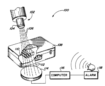
FIG. 1 is a simplified schematic diagram of a
nuclear-based contraband detection system:
FIG. 2 is a schematic spectrum of prominent
gamma-rays with energies greater than 1 MeV that are
emitted in bombardments of hydrogery:, carbon, nitrogen and
oxygen with a steady beam of l4 Me« neutrons:
FIGS. 3A-3C are,represent:ative energy spectra
obtained from various materials that have been irradiated
with a beam of 14 MeV neutrons:
WO 91/11009 PCT/US91/00179
-18-
FIG. 4 illustrates a schematic representation
of the principal hardware components that may be included
in a contraband detection system in accordance with one
embodiment of the present invention;
FIGS. 5A and 5B schematically illustrate the
basic components of the nuclear-based detection system of
the present invention, which components are used to
interrogate objects suspected of containing contraband
using gamma-ray spectroscopy based on the inelastic
scattering of fast neutrons, with the embodiment in FIG.
5A not including a narrow collimator, and the embodiment
in FIG. SB including such a collimator; and
FIG. 6 is a schematic diagram showing one
example of the flow of data and controls used in the
embodiments of the present invention.
Detailed Description of the Invention
The following description is of the best mode
presently contemplated of carrying out the invention.
This description is not to be taken in a limiting sense,
but is made merely for the purpose of describing the
general principles of the invention. The scope of the
invention should be determined with reference to the
claims.
For the sake of greater clarity in the
description of the present invention, a particular
embodiment providing for the fast detection of concealed
explosives is described. However, embodiments of the
present invention in the detection/control of other
substances/materials are easily carried out by those
skilled in the art of nuclear spectroscopy using the
herein described apparatus and methods. For example, any
material having a characteristic radiation "signature"
(e. g., resulting from a specific combination,
concentration, and/or arrangement elements) as a result
of inelastic scattering of fast neutrons, could be
WO 91/11009 PGT/US91/00179
-19-
identified using the methods and apparatus described
herein.
The present invention is based on the
phenomenon that fast neutrons of MeV energies induce
prompt gamma-ray transitions from the low lying levels in
target nuclei. Advantageously, the corresponding cross
sections are reasonably large, and for instance in the
case of 'ZC, ~4N, and '60 are greater than the neutron
radiative capture cross sections at thermal neutron
energies. However, because the neutron incident energy
must exceed the excitation energy of the nuclear level to
be excited, the neutrons must have energies greater than,
e.g., 6.7 MeV if :measurements of the gamma-ray
transitions in X60-with 14 MeV neutrons are contemplated.
Rising the neutron energy;too high is counter-productive
because the number of the reaction channels increases
rapidly, thereby often causing reduction of the desired
cross section, and also initiating the production of many
undesirable delayed radioactivities as a side effect.
However, for practical reasons, it is preferable to use,
a.g., 14 MeV neutrons, as the input beam in the gamma-ray
spectrometry analysis performed by the present invention.
Advantageously, there are readily available generators of
14 MeV neutrons, and he production of the desired gamma-
.25 ray lines is satisfactory at this bombarding neutron
energy. Also, there is available a great body of
evaluated data on interactions of 14 MeV neutrons with
nuclei;; which facilitates the assessment of
the densities of the target nuclei and the design of
efficient biological shielding for use with the l4 MeV
neutrons.
As an overview of the present invention,
reference is made to FIG. 1, where a simplified schematic
diagram of a nuclear-based explosive detection system 100
is illustrated. The system includes a neutron generator
(ion accelerator) source 102 that produces beams of
WO 91/11009 PGT/US91/00179
-20-
neutrons 106. The neutron source 102 may include a
collimator 104, or equivalent structure, that directs the
neutron beams 106 towards a desired object, such as
luggage 108, so as to irradiate a specified section of
the luggage with neutrons. The probing neutrons interact
with the explosive material 110, placed inside the
luggage 108, and induce it to emit gamma rays. The
number and energies of the emitted gamma rays are
measured in a detector 114.
Certain elements of interest, such as hydrogen
(H), carbon (C), oxygen (O) and nitrogen (N), show up in
the energy spectrum as peaks (lines of interest) at .
particular positions in the measured spectrum. By using
appropriate processing circuits, the presence or absence
of such energy peaks is monitored using a computer 116.
If prescribed signatures of such elements are found to be
present within at least one particular small subsection
of luggage volume, or " voxel", of the luggage 108, such
finding suggests that explosives are present in that
voxel of the luggage. In such instance, an alarm 118 is
triggered. This alarm (which may be audio and/or visual)
alerts operating personnel that explosive material 110
may be present within the luggage 108.
Advantageously, by limiting the triggering or
sounding of the alarm only to situations where specific
combinations and densities of prescribed elements are
present, as determined by appropriately monitoring and
processing the spectrum of the gamma rays, a high
probability of detection (PD) of the explosive material
can be obtained while maintaining a low probability of
false alarms (PFA).
The above description (presented in connection
with FIG. 1) is, of course, greatly simplified.
Nonetheless, it illustrates to those less familiar with
gamma-ray spectroscopy the manner in which the present
WO 91/11009 PGT/US91/00179
-21-
invention non-invasively detects a ;specified type of
contraband, such as explosives, witlhin a closed object.
For those having more familiarity with gamma-
ray spectroscopy; reference is next made to FIG. 2 where
there is shown a schematic, spectrum of prominent gamma-
ray -with energies greater than 1 MeV that are emitted in
bombardments of hydrogen, carbon, nitrogen and oxygen
with a steady beam of l4 MeV neutrons. The cross
sections of these atomic nuclei for the production of the
indicated gamma-ray lines are plotted on the logarithmic
scale in units of 10'Z~ cmz (millibarws) : (The concept of
nuclear cross sections is well understood by those
skilled in nuclear spectroscopy, arn3 is fully described
in the literature, see, e.g., Gozan.i, Active
Nondestructive Assay of Nuclear Materials, su ra; at
pages 36-40.) The spectral lines :labelled l, 3, 6, 8
(minor part), 9; ll, and 13 are due to nitrogen. The
spectral lines labeled 4, 5; 7, 10, 12, and 14 are due to
oxygen. The spectral line 8 is due to carbon.
Similarly, the spectral line labeled 2 is due to
hydrogen, this line resulting from<:radiative capture of
neutrons by hydrogen. (Note, that °the intensity of this
particular line is set arbitrarily :in FIG. 2.)
To illustrate the manner :in which the
information presented in FIG. 2 is °to be read, a basic
understanding of the manner in whiclh nuclear interactions
occur and the corresponding measurements are made is
helpful:. The relevant literature fiully documents such
interactions and measurement echni;~ues, see, e.g:,
Gozani, Active Nondestructive Assav of Nuclear Materials.
Principles and Applications, supra; Knoll, G,F.;
Radiation Detection and Measurement, John Wiley & Sons
(1979). When a neutron enters a given material, e.g.,
nitrogen, it has-some probability to collide with an
atomic nucleus, depending upon the cross section of
target nucleus and the neutron incident energy. A gamma-
WO 91/11009 PCT/US91/00179
-22-
ray is emitted only when a given amount of energy is
transferred to the target nucleus. Appropriate detectors
can be positioned to absorb such gamma-rays and to
measure their energy. The probability that an
interaction will occur (and hence the probability that a
gamma-ray will be emitted) significantly increases with
the fluency of neutrons.
Thus, with reference to FIG. 2, the heavy
spectral lines, e.g., lines 2, 3, 8, 9 and 10 reflect the
fact that gamma-rays with the indicated energies are more
likely to occur when the identified elements having the
indicated nuclear cross sectional areas are bombarded
with 14 MeV neutrons. The lighter spectral lines, e.g.,
lines 1, 4, 5, 6, 7, 11, 12, 13 and 14, indicate that
gamma-rays at the indicated energy levels may also occur,
but not as frequently. Said another way, most of the
gamma-rays emitted from hydrogen, carbon, nitrogen and
oxygen when irradiated with 14 MeV neutrons will appear
as strong spectral lines 2, 3, 8, 9, and 10; while lines
1, 4, 5, 6, 7, 11, 12, 13 and 14 will be rather weak, or
not measurable for technical reasons.
In contrast to FIG. 2, which shows a schematic
spectrum of emitted gamma-rays from carbon, hydrogen,
nitrogen and oxygen that would be measured assuming ideal
measuring equipment and conditions, FIGS. 3A through 3C
show actual gamma-ray spectra measured using realistic
(non-ideal) measuring equipment and conditions when
various samples, many of which contain combinations of
hydrogen, nitrogen, carbon, and/or oxygen, are irradiated
with 14 MeV neutrons. Note that the vertical axis of the
spectra shown in FIGS. 3A through 3C is measured in
"counts", where one count indicates the detection of a
pulse (due to gamma ray interaction in the scintillator)
of the particular energy indicated on the horizontal
axis. These figures are useful to show the versatility
of the present invention in being able to identify the
WO 91/11009 PGT/US91/00179
~~~~~~~
-23-
"signatures" of different'types of-contraband. (Here, a
"signature" of a material comprisesc the characteristic
types,-intensities; and energies o!: the-radiation, e.g.
gamma-rays, emitted by -that material when- irradiated with
fast neutrons.) These.figures'also illustrate the
difficulty in recognizing a specified signature due to
background or instrumental noise treat appears in the
spectrum.
Referring next to FIG. 4, a schematic
representation of the principal hardware components that
may be included in a contraband detection system in
accordance with one embodiment of the present invention
is illustrated. A source of fast neutrons 130 directs a
beam l32 of neutrons towards an object 134, the contents
of which are to be investigated. In a preferred
embodiment, a collimator 136 shapes the neutron beam 132
to assume a desired cross sectional: shape at the point
where it strikes the object 134. As shown in FIG: 4, for
example, the cross sectional shape of the beam 132 may
assume that of a narrow rectangle 1.38 at the point where
it strikes the object 134:
The object 134 is carriedl past the beam 132
within a shie3ded chamber 135 on a conveyor belt 140, or
equivalent parcel-carrying mechanism. The conveyor belt
140 is driven by a motor 142 in a continuous or step-wise
fashion. The conveyor belt l40 continues to carry the
object 134 through a chamber of a conventional X-ray
system 150 wherein a source of X-rays-152 and a
corresponding detector (not shown) are used to produce an
ordinary electron density image of the object and its
contents.
It is noted that while the X-ray system 150 is
shown as a separate system from the. nuclear portion of
the invention (e. g:, chamber 135), such physical
separation is shown only for clarity. A particular
embodiment of the invention may include the nuclear and
WO 91/11009 PCT/US91/00179
-24-
X-ray portions of the invention within the same physical
housing.
An array 144 of gamma-ray detectors are
selectively positioned around the object 134 as it is
irradiated by the neutron beam 132 within the nuclear
chamber 135. In one embodiment, this array forms a C-
ring that surrounds three sides of the object as it is
irradiated, as shown in FIG. 4. (Note in FIG. 4 that
only an upper portion of the C-ring detector array 144 is
visible.) An alternative embodiment, refer for instance
to Fig. 58, utilizes arrays of detectors~that form bars
positioned "fore",and "aft" of the interrogated sample.
Still other embodiments utilize a detector array that
comprises a full ring that completely surrounds the
object as it is irradiated. In addition to the array of
gamma-ray detectors 144, at least one neutron detector
146 is placed behind the object 134 in alignment with the
source of neutrons 130. This neutron detector 146 thus
registers mainly neutrons that manage to pass through the
chamber 135 and the object 134 without interacting
substantially with any intervening atomic nuclei.
Appropriate control circuits 148 interface with
the above-described components. The control circuits, in
turn, are monitored or driven by a suitable computer 154.
The computer 154 includes conventional input/output
devices, such as a keyboard 156, a terminal display
screen 158, and/or a printer (not shown). Additional
devices 160, such as a non-volatile memory (e.g., disk or
tape memory) may also be coupled to the computer 154, as
required, in order to facilitate operation of the system
to collect and/or retrieve or track the historical data
that may be needed to assure a fast and reliable system
performance relative to detection of various contraband.
For example, it is contemplated that one such additional
device 160 that may be coupled to the main computer 154
is an auxiliary computer, adapted specifically to
CA 02046896 2001-04-18
-25-
interface with personnel who operate the detection
equipment.
In operation, the object 134 is irradiated by
the beam 132 in sections or slices as the object moves
past the beam. The gamma-rays resulting from, the
interaction of the neutrons with atomic nuclei in the
irradiated slices of the object are detected in the
gamma-ray detector array 144. The intensity of the
neutrons that pass through the chamber 135 and object 134
are measured by the neutron detector 146. The number of
gamma-rays of specified energies detected by each
' detector in the array provides a measure of the amount of
the particular element present within the irradiated
voxel of the object. By combining this information from
all of the detectors, as well as by considering the
number of neutrons that pass through the object (fluence
of neutrons), both spatial and density distributions of
the particular elements within the irradiated object are
obtained. (Note, as used herein, "spatial" distribution
refers to the location of a particular elements) within
a defined space. A "density" distribution refers to the
amount of a particular element that is present at a given
location within the given space.) Such spatial and
density information thus allows a three-dimensional
spatial and density image of the elemental (nuclear)
constituents of the object to be derived. The nuclear
spatial and density information thus obtained may be
further enhanced by combining it with the electron
density information obtained from the X-ray system 150.
If such combined spatial and density information suggests
the presence of contraband, the object is flagged for
further investigation (e. g., diverted off of the conveyor
belt for a manual search).
As indicated in FIG. 4, it is preferred that
the neutron beam 132 be directed toward the interrogated
object 134 using a collimator 136. The collimator 136
WO 91/11009 PCT/US91/00179
_26_
may be of conventional design, and is comprised of
neutron scattering, and absorbing materials of densities
that ensure a desired tailoring of the cross section of
the beam, including the reduction of the neutron flux
impinging on the gamma-ray detectors. The gap of the
collimator thus defines, e:g., a narrow fan-shaped beam
of source neutrons that bombard a known section or volume
element, i.e., of the interrogated object. The use of,
e.g., several collimators 136 advantageously allows a set
of fan-shaped neutron beams to be generated, thus
facilitating the building of independent irradiation
stations and assuring greater economy of the source
neutrons, if so desired. Further, by directing the
shaped beam only to a desired section or voxel of the
object, the neutron irradiation is maintained more
homogeneous throughout the section or voxel than would be
possible if the unrestricted neutron beam irradiated the
entire object.
FIGS. 5A and 58, show schematic illustrations
of two embodiments of the basic components used by the
nuclear-based portion of the present invention. The
embodiment of FIG. 5B includes a neutron beam collimator
136, while the embodiment of FIG. 5A provides almost no
collimation. The latter may be inferior to the former in
spatial definition, but requires a weaker neutron source.
Except for that difference, the two embodiments are
essentially the same and will thus be described jointly.
It is noted that like parts or elements of FIGS. 5A and
58 utilize the same reference numerals as like parts or
elements of FIG. 4.
In FIGS. 5A and 5B, the neutron source 130
comprises a fast neutron generator 170 surrounded by a
biological shield 172. The neutron source may be any of
several commercially available generators of fast
neutrons, e.g., a D+T (deuterium plus tritium) generator,
such as the model A711 generator made by Kaman Nuclear of
WO 91/11009 PCT/US91/00179
-27-
Colorado, the TN46 or TN26 neutron generators made by
Sodern (France), or any other suitable neutron generator,
such as a D+D (deuterium plus deuterium) generator, a
D+Be (deuterium plus beryllium) generator; or a H+Li
(light hydrogen plus lithium) generator. The biological
shield 172 is used to shield operating personnel from
radiation that may be potentially harmful. It may be
made from-any of several suitable substances, commonly
known and used for shielding in the nuclear art, and is
typically a composite material made of several
substances, such as boron wax, polyethylene, and heavy
metal -(e. g., lead, bismuth, or tungsten).
As previously described, 'the collimator 136,
when used (FIG. 5B), forms the beam 132 of neutrons into
a desired cross sectional shape. Preferably, this will
be a fanned shape (out of the drawing plane in FIGS. 5A
and SB) that ensures irradiation of a desired volume 138
( hown in cross-hatch) of the object 134. Even where the
collimator is not used (FhG. 5A), the shielding 172 still
limits the irradiated front area of the object 134 so as
to define a somewhat predictable volume slice or portion
138'. The wavy arrow 174 schematically shows the path of
the gamma-rays that result from neutron interaction at
point 176 in the irradiated volume 138 of the object 134.
A plurality of detectors 178, 179, 180 and 181
are schematically shown in FIGS: 5A and/or 5B as
representative of the detectors that are included in the
detector arrays 144 used with the present invention. In
a preferred embodiment, these detectors are gamma-ray
scintillation detectors that surround the object 134
under investigation. Preferably the detectors 178 and
181 are either stacked (out of the plane of the drawing)
in arrays that form two C-shaped rings; or in two 0-
shaped rings, in which case the detectors 178 and 180 are
included in the same O-shaped ring, as are the detectors
179 and 181. Each of the detectors 179-181 is surrounded
8
WO 91/11009 PGT/US91/00179
-28-
by an appropriate detector shield 182. Alternatively,
arrays of detectors may be used that form straight bars,
positioned, e.g., behind the object. Further, it is
mandatory for radiological reasons that the entire
facility be shielded with an additional biological shield
184.
As indicated above in FIGS. 4, 5A and 5B, the
prompt gamma-ray lines that ensue from irradiation of the
object 134 with fast neutrons are measured by gamma-ray
detectors. In embodiments of the present invention
directed to the detection of explosives, scintillators
are used as the gamma-ray detectors. For example, one
type of.scintihlator that may be used to detect gamma-
rays is an inorganic scintillator crystal, such as sodium
iodide (NaI(T1)) or bismuth germanate (BGO).
Advantageously, scintillator detectors provide
satisfactory spectral resolution in measurements of
gamma-ray lines that indicate explosives, as indicated in
Table 1 and Figure 2. In accordance with that which has
been learned by the applicants of the present invention
from experiments carried out with 14 MeV neutrons in
realistic conditions, the preferred set of spectral
lines, i.e., the spectral lines that comprise the
signatures of explosive constituents, include lines 2, 3,
8, 9, and 10. See FIG. 2.
An important feature of the present invention
is the ability of the processing circuitry, included in
the control circuits 148 and the computer 154 (FIG. 4) to
generate or create three-dimensional images of the
density distributions of specified constituents of the
contraband of interest. For example, where the
contraband is explosives, three-dimensional (3-D) images
of the explosive constituents H, C, N, and O contained
within the object 134 are obtained. These distributions
are obtained from the measurements of the signature
gamma-ray lines which originate in the geometrically
CA 02046896 2001-04-18
-29-
well-defined small volume elements (voxels) of the
irradiated object 134. This 3-D mapping is achieved by
utilizing the well known effect of the combined solid-
angle and detection efficiency of finite size
scintillation crystals, i.e., suitably choosing the sizes
and shapes of the crystals, their positions versus the
voxels, the opening gap of the neutron beam collimator,
and the stepwise or continuous motion of the object
relative to the neutron beam used to ensure its complete
and homogeneous inspection.
As is known to those skilled in the nuclear
arts, a scintillator is any material capable of emitting
low energy photons (in the visible and near visible
range) when high energy radiation, e.g., gamma-rays,
interacts therewith. In the case where an inorganic
scintillator crystal, such as NaI, is used, a faint
visible light results when the crystal is struck with a
gamma ray. This light is converted to an electrical
pulse by a photomultiplier tube. The voltage of the
2o pulse is proportional to the energy of the gamma ray.
Thus, the processing circuitry used with the scintillator
detector arrays) of the present invention must be
capable of measuring and counting the pulses, and hence
the gamma-rays. Several problems are encountered in
performing this task, especially if the count rates are
high. These problems, and a preferred solution thereto,
are described in Drndarevic, et al., "A Signal Processor
for High Counting Rate Gamma Ray Spectroscopy with
NaI(Tl) Detectors," .IEEE, Proceedings of Nuclear Science
(February 1988 ) .
Using pulse handling circuits such as those
described in the referenced article, count rates greater
than 105 Hz may be used. Such high count rates
advantageously permit prompt elemental analysis of the
WO 91/11009 PCT/US91/00179
-30-
object to be performed, thereby maintaining a suitable
fast throughput for the contraband detection system.
A further feature of the present invention is
to include one or more neutron detectors 146 in addition
to the gamma-ray detectors included in the detector
arrays) 144. The use of such a neutron detectors)
enables the measurement of the flux of fast neutrons at
the detector position(s). In turn, such neutron flux
measurement provides an indication of the density of the
atomic nuclei of the material through which the neutrons
have passed. Combining this density information for all
of the voxels of the irradiated object thus allows a
three dimensional image of the nuclear density of the
object to be performed, as is commonly done.while
performing neutron radiography. This neutron radiography
image may be combined with the three dimensional image of
the density of the constituent elements of the object
obtained from the gamma ray detectors. When such images
are further combined with the two-dimensional electron
density image obtained from the conventional X-ray system
150, the probability of detecting specified contraband
(without falsely alarming on benign materials) is
significantly enhanced.
In one embodiment of the present invention, the
investigated moving object 134 is interrogated in a
"once-through-pass" of the object through the irradiating
cavity 135. In another embodiment, the investigated
moving object 134 is interrogated in a double irradiation
regime with interchanged top-bottom sides.
As indicated in FIG. 4, the present invention
utilizes various electronic sensors or controls and
processing circuits 148 to perfona its function of
irradiating an object and analyzing the resulting
radiation to determine its constituent elements and their
distribution. In order to illustrate the organization of
the corresponding software used in the computer 154 to
WO 91/11009 PGT/US91/00179
-31-
interface with such control and/or processing circuits,
reference is next made to FIG. 6 where there is shown a
schematic diagram showing one example of the flow of data
and controls used in the embodiments of the present
invention.
A central processing unit (CPU) module 190
resides at the heart of he contraband detection system.
Clnce valid signals from the detectors and sensors have
been acquired, the CPU module 190 carries out or controls
~10 the analysis of the data from the detectors/sensors. It
then delivers the results to module 192, which is
dedicated to data merging and decision making. For
decision making, module 192 uses the method of
Statistical Discriminant;Analysis, or an Artificial
Neural System (ANS), e.g., an electronic neural network.
CPU module 190 further issues the signals that control
the subsystems, i.e., modules 194-199.
Module 194 in FIG: 6 represents the gamma-ray
detectors, e.g., the detectors l78-181 (FLGS. 5A and 58),
and includes circuitry that governs the electronic
signals from the gamma-ray detectors and the various
control circuits that adjust and monitor the electrical
settings of these detectors:
Module l95 represents the circuitry, including
controls, associated with the standard or position
sensitive neutron detector(s), such as the neutron
detectors) 146 (FIGS. 4, 5A and 5B), used to perform
neutron radiography analysis of the object under
investigation.
Module 196 represents the actuators and
controls or mechanical devices used with the present
invention, e.g., the conveyor belt drive motor 142,
diverters, and safety doors. Diverters are used to
divert objects off of the conveyer belt when a
determination i made that the object contains specified
contraband. Safety doors are used to protect operating
a
WO 91/11009 PCT/US91/00179
-32-
personnel from radiation that might otherwise escape from
the irradiation room.
Module 197 represents the neutron generator
130, and the various control circuits used to control the
operation of the neutron generator 130.
Module 198 represents the systems radiological
controls, i.e., those controls used throughout the system
to ensure the system is safe for operating personnel, and
that the induced radioactivity in the interrogated items
l0 is not exceeding prescribed levels. Such radiological
controls are standard in the nuclear industry.
Module 199 represents ah optionah conventional
X-ray subsystem, such as the X-ray system 150 shown in
FIG. 4, that provides digitized images of electron
density distributions in the object.
Module 192 contains the software that supports
the final data analysis and decision regarding the
character of the contents of the object under
investigation. This module facilitates e.g.,
construction of the 3-D image of distributions of H, ~ZC,
~4N, and X60 nuclei, and merging these nuclear density
distributions with the electron density maps obtained
with the X-ray subsystem module 199, and with the
radiographs obtained with the neutron radiography
detectors 195. In addition, Module 192 provides a means
whereby the user can interact with the system, and
provides a means for status displays and the updating of
historical record files.
Advantageously, the present invention may
include multiple processors within the CPU module 190,
the data evaluation module 192, or any other modules
shown in FIG. 6, which multiple processors are designed
to operate in parallel, thereby significantly reducing
the processing time required to perform an analysis of a
given object. In turn, such reduced processing time
further allows the rate at which objects can be passed
WO 91/11009 PCT/US91/00179
~=~~~
-33-
through the contraband detection system (the"throughput"
rate) to be increased.
It is further noted that the use of parallel
processors also allows some functions of the indicated
modules to be combined or omitted, and the data and
control parts to be rerouted or deleted. Hence, it is to
be understood that the system organizational diagram
shown in FIG. 6 is not necessarily the only scheme of
data and/or control flow in the embodiments of the
,10 present invention, as numerous alternative and/or
equivalent schemes could readily be fashioned by those
skilled in the art.
As thus described, it is seen that the
contraband detection system of the. present invention
provides a nuclear-based non-invasive detection system
that accurately and rapidly determines the presence of
concealed contraband, such as explosives, within a closed
object. In particular, for the disclosed embodiment, the
detection system accurately identifies the presence of
one or more of the elements hydrogen, oxygen, carbon
and/or nitrogen, and/or other elements (e. g., chlorine):
and further generates an image of the three-dimensional
density distribution of such elements, or otherwise
provides information on the spatial and density
distributions of such elements, within the object being
investigated. Such an image advantageously allows
contraband to be detected regardless of the shape that
the contraband assumes within the abject. By including
within the system both gamma-ray and neutron detectors,
a 30 as well as a conventional X-ray system, it is thus
possible for the system to exhibit a high probability of
detecting specified contraband, while at the same time
ensuring a low probability of false alarms, all while
maintaining a high throughput of objects therethrough.
Such system is easy and safe to operate: and, as it turns
WO 91/11009 PGT/US91/00179
-34-
out, is non-hazardous to the interrogated objects,
operating personnel, and the environment.
While the invention herein disclosed has been
described by means of specific embodiments and
applications thereof, numerous modifications and
variations could be made thereto by those skilled in the
art without departing from the scope of the invention set
forth in the claims.