Note : Les descriptions sont présentées dans la langue officielle dans laquelle elles ont été soumises.
WO 94/25915 ~ ~~ PCTIUS94I04462
Holographic Operator Interface
Background of the Invention
The present invention relates generally to a holographic operator
interface to electronic or electromechanical devices such as data processing
units or computers and, more particularly, to a holographic operator
interface where there is no tangible physical contact between the operator
and the control elements of the operator interface as the input devices are
holographic images of the keys or other customarily touch-activated tangible
input devices. Operator interaction is detected through electromagnetic or
other means, thereby obviating the need for direct physical contact with a
solid input object or surface.
There are many methods and devices available for entering data and
commands into computers, such as pushbuttons, keyboards, trackballs, mice
and light pens. All of these input devices share a common disadvantage in
that they require tangible physical contact by the user of the computer or
electronic device. The repetitive physical effort required to operate solid
keyboards has been shown to cause or promote physical maladies, including
carpal tunnel syndrome. Even where only one person uses the input device it
is inherently subject to wear and damage because of the mechanical aspects
of these input devices. Where many individuals use an input device
throughout the day, such as in a bank's automated teller machine, problems
of normal wear and tear are exacerbated by constant use, a potentially
inhospitable environment and hygiene concerns. These hygiene concerns are
particularly relevant in sterile environments such as a hospital operating
WO 94/25915 PCT/US94104462
2
room where it is desirable to control electronic equipment without physical
contact that may compromise sterility. These standard input devices share an
additional disadvantage in that one input device cannot be commonly used to
control several electronic devices without physically disconnecting and
reconnecting the input devices, thereby necessitating the use of several
similar input devices rather than one remotely connected input device.
Additionally, changing the notation or arrangement of the input devices is
generally impractical because of the problems inherent in replacing keycaps
or altering a keyboard arrangement.
Electromechanical keyboards and keypads are the most common
operator interface for inputting data and commands into electronic devices
such as computers. However, these devices are unsuitable for certain
environments and it is considered desirable to reduce the use of
electromechanical relays because of their inherent problems. Furthermore,
they have been shown to cause or promote the aforementioned physical
maladies in part because they require the repeated application of physical
pressure. Previous attempts to provide operator input without using
electromechanical devices have included a "Keyboard With Immobile Touch
Switches," U.S. Patent No. 3,372,789, issued March 12, 1968 to H. Thiele et
al. and a "Motionless Data Input Key," U.S. Patent No. 3,340,401, issued
September 5, 1967 to J. E. Young. The devices disclosed in these patents,
while eliminating the need for electromechanical relays, still require the
user
to physically touch the input device to actuate it.
Although holographic images are used in other operator interfaces,
they are used as visual output devices (displays) rather than as input
devices.
Head-up displays such as those used in aircraft or the "Holographic Head-Up
Control Panel" described in U.S. Patent No. 4,818,048 issued April 4, 1989 to
G. Moss exemplify this use of holograms in output devices. In these
implementations of operator interfaces the holographic image provides
information and feedback responsive to the operator's actuation of solid
controls separate and distinct from the holographic image.
This invention is directed toward providing a means by which an
CA 02160245 2003-12-30
67529-113
- 3 -
operator may control one or more devices without touching a
solid control object or surface while still interacting with
familiar controls that are visually perceived, such as a
keyboard.
Summary of the Invention
According to the present invention, there is
provided a control arrangement for allowing an operator to
control an electronic device comprising: an image generator
for generating a holographic image of a physical control
panel of the electronic device; an actuation detector for
determining a section of the holographic image which is
selected by the operator; and a signal generator for
receiving the determination of said actuation detector and
providing input signals to the electronic device which
correspond to input signals from said physical control panel
as a result of this determination.
Also according to the present invention, there is
provided a method for inputting data to an electronic device
to be controlled by an operator comprising the steps of:
producing a holographic image of a physical input device
that is customarily actuated to provide input to the
electronic device; determining a series of sections of the
holographic image which are selected by the operator in a
logical sequence; and providing input signals to the
electronic device which correspond to input signals from
said physical input device as a result of said
determinations thus allowing the operator to use familiar
physical input device control methods while avoiding
physical contact with the physical input device.
Embodiments of the present invention provide an
interface between an operator and a device to be controlled.
CA 02160245 2003-12-30
67529-113
- 3a -
The operator interface includes an input interface that
permits the operator to input data and commands into a
device such as a computer without requiring physical
contact. The input interface includes a holographic image
of a physical input device -- the operator activates the
input interface without physically touching a solid control
surface. The input interface is activated when the user
passes a finger or pointer through the holographic image of
a key or other input device. Operator actuation is detected
through electromagnetic radiation or sound energy, allowing
the operator to use familiar key controls while avoiding
physical contact.
The input interface incorporates a three-
dimensional holographic image of a keyboard or other input
device projected from a hologram of the input device. The
hologram may be either a reflection hologram or a
transmission hologram, the type of hologram used dictating
the relative position of the light used to project the
three-dimensional holographic image.
The operator interface may optionally include an
output interface, such as a conventional video display used
in personal computers.
Brief Description of the Drawings
FIG. 1 is a schematic functional representation of
a holographic operator interface according to the principles
of the invention.
FIG. 2 is a schematic representation of an image
generator used in the operator interface of FIG. 1.
CA 02160245 2003-12-30
67529-113
- 3b -
FIG. 3 is a schematic representation of a first
embodiment of an input actuation detector used in
conjunction with the image generator of FIG. 2.
FIG. 4 is a schematic representation of a second
embodiment of an
21~'~~~j
WO 94/25915 PCT/US94104462
4
input actuation detector.
FIG. 5 is a schematic representation of the relative position of a
hologram, a holographic image, and an illumination source for use in the
image generator of FIG. 2.
S Detailed Description
FIG. 1 schematically illustrates a holographic operator interface 2
between an operator 1 and a device 3 to be controlled by the operator 1.
Device 3 may be an electronic device such as a computer or any other
device into which it is desired to provide user input through a keyboard,
keypad or other input device and which may provide visual or other output to
the operator. Such devices can include automatic teller machines, electronic
cash registers, personal computers, calculators, data entry keypads, system
controls, weapons systems, musical instruments, electronic testing equipment,
video recorders, televisions, telephones and switchboards.
The operator interface 2 includes an input interface 20, which includes
a holographic image generator 200, an actuation detector 300, and a signal
generator 400. The operator interface 2 may optionally include an output
interface 25, which can include a display 500.
The holographic image generator 200 generates a holographic image
of an input device such as a keyboard. The operator can see the image of
the input device and actuate the input interface 20 by penetrating the image
with a finger or other pointer. Actuation detector 300 senses the operator's
physical indications, determines which part of the input device image the
operator actuated, and conveys that information to the signal generator 400.
Signal generator 400 incorporates the means needed for communication
between actuator detector 300 and the device 3. Signal generator 400
provides input signals to the device 3 which may, for example, correspond to
standard input signals from electromechanical keyboard or keypad input
devices. Thus, the operator's manipulation of the image generated by the
image generator 200 is ultimately conveyed by signal generator 400 to the
device 3 that the operator wishes to control
WO 94/25915 ~ ~ PCTIUS94104462
S
Each of the functional components of the operator interface 2 may be
physically separated from each other and from the device 3 -- the image
generator 200 need only generate an image that is physically accessible to the
operator 1, and the display 500 need only be visible to the operator. Thus,
the image generator may be physically separated from the actuation detector
300, so that the sensing of the operator's manipulation of the image may be
done remotely. The actuation detector may be physically combined with or
separated from the signal generator 400, which in turn may be combined with
or separated from the device 3. The display 500 may be combined with or
separated from any of the other components. Information to be
communicated between the actuation detector 300, signal generator 400, and
device 3, and between device 3 and display 500, may be communicated via
any suitable data link (indicated in FIG. 1 as links 305, 405, and 505). Each
such data link may include any suitable means for communicating data, such
as a mufti-conductor wire or an infra-red or radio frequency link of the kind
commonly used for microcomputer keyboards and entertainment device
remote controls.
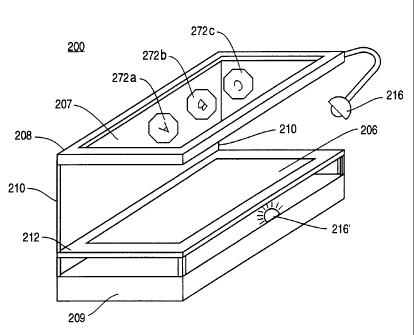
As illustrated schematically in FIG. 2, image generator 200 provides
an intangible input device in the projected holographic image 207 of an input
device recorded in hologram 206. The image may include images of
individual keys 272a, 272b, and 272c. Hologram 206 is disposed on body 209
(such as by mounting on a support 212, which may be transparent if a
transmission hologram is used). Holographic image 207 is projected above
hologram 206 and body 209 such that holographic image 207 appears
approximately coplanar with an image frame 208 supported on the mounting
body 209 by suitable supports 210. The image frame 208 may provide a wrist
rest for the operator, and may support an upper illumination source 216.
Alternatively, a lower illumination source 216' may be used, as described
below. Mounting body 209 may also house the actuation detector 300 and/or
the signal generator and their associated electronics, a power supply, and
any other related equipment.
As is well known in the art, a hologram is a photographic record of
WO 94/25915 ~ PCTIUS94/04462
6
the interference pattern formed by two light beams, a reference beam
directed toward the photographic film and an object beam reflected from the
object to be shown in the hologram. When a hologram is illuminated by a
reconstruction beam, it produces a real image (which appears to be between
the plane of the hologram and the viewer) and a virtual image (which
appears to be behind the plane of the hologram). As illustrated in FIG. 5, it
is preferred that the holographic image 207 produced from the hologram 206
by reconstruction beam 266 appear to the operator (the operator's eye being
represented schematically in FIG. 5 at 10) to be located between the
operator and the hologram 206, so that the operator can "touch" the
holographic image 207 without encountering the hologram 206. Thus, it is
preferred that the holographic image 207 be a real image.
However, with a conventionally-developed hologram, the real image
appears to be inverted (i.e. a mirror image) -- it is thus pseudoscopic. This
may be undesirable for an image of an operator interface such as a keyboard.
However, a true, or orthoscopic, real image may be produced by a process of
double inversion whereby a second hologram is made of the pseudoscopic
real image of a hologram of an actual object. The resulting real image from
the second hologram, being a pseudoscopic image of a pseudoscopic image
from the first hologram, is therefore orthoscopic. Hologram 206 is preferably
formed pursuant to this procedure so as to create an orthoscopic image of
the input device. The procedures for forming such a hologram can be found
in known reference works such as "Optical Holography" by Collier et al.,
Academic Press, New York (1971), "Three-Dimensional Imaging Techniques"
by Okoshi, Academic Press, New York (1976), and "Optical Holography:
Principles, Techniques and Applications" by Hariharan, Cambridge University
Press, Cambridge (1984).
Holographic image 207, projected from hologram 206, is an
orthoscopic real image of the input device and is disposed so as to be
approximately coplanar with image frame 208. As the artisan will recognize,
if hologram 206 is a transmission hologram, the illumination source 216'
providing the reconstruction beam 266 for holographic image 207 is
WO 94/25915 ~ ~ ~ ~ ~ l~ ~ PCT/US94/04462
7
positioned behind hologram 206 relative to the operator, whereas if hologram
206 is a reflection hologram the illumination source 216 is positioned on the
same side of the hologram as the operator. As is well known in the art,
conventional holograms require a coherent reconstruction beam, while other
types of holograms are viewable in incoherent white light. Thus, if the
hologram 206 is a white-light hologram, the illumination source 216 may be a
source of incoherent light, such as a halogen lamp, while if the hologram 206
is a conventional hologram, the illumination source 216 must be a source of
coherent light, such as a laser.
The placement of the illumination source 216 may also vary with the
physical configuration of the input interface 20 and the environment in which
it is operated. For example, if the image generator 200 is to be stationary
(as, for example, if it is used with a bank's automated teller machine), the
illumination source may either be mounted to the base 209 or may be
mounted remotely from the base, such as on the device 3, or on a nearby but
separate structure. If the image generator is to be movable, the illumination
source 216 should be mounted in a fixed relationship to the image generator
so that the incident angle of the reconstruction beam on the hologram
remains fixed.
Techniques for generating a holographic image from either a
transmission or reflection hologram are well known in the art and can be
found, for example, in the above listed reference works. Techniques for
creating and viewing rainbow holograms are described in "White Light
Transmission/Reflection Hologram Imaging" in "Applications of Holography
& Optical Data Processing" by Benton, ed. Marom et al., Pergamon Press,
Oxford (1977).
The operator 1 is thus presented with a holographic image 207 of an
input device. The operator interacts with the image by passing a finger or
pointer through the apparent plane of the image 207. Detection and
interpretation of operator interaction with the holographic image 207 is
performed by the actuation detector 300. As described above, the actuation
detector may be connected to, or may be physically separated from, the
WO 94!25915 ~ ~ ~ PCTlUS94/04462
8
image generator 200. In the preferred embodiment, the image generator 200
and actuation detector 300 are physically integrated.
As illustrated in FIG. 3, the actuation detector 300 may consist of an
optical detection matrix 311 integrated with image frame 208. Image frame
208 is formed as a rectangular polygon approximately coplanar with and
peripherally encompassing holographic image 207. Optical detection matrix
311 consists of photoemitters 312 and corresponding photoreceptors 313
arranged such that two or more mutually perpendicular detection beams 314
and 315 are blocked when the operator actuates a unique element (such as
individual keys 272a, 272b, or 272c) of the input device by "touching" the
corresponding portion of the holographic image 207. The identity of the
intersected detection beams can be correlated with the key that has beefs
actuated by any suitable technique, such as be reference to a look-up table.
Such an optical detection matrix (but using a physical keyboard) is described
in U.S. Patent No. 4,884,073 issued November 28, 1989 to A. Souloumiac.
In an alternative embodiment, actuation detector 300 may incorporate
a laser measuring device utilizing measuring techniques such as the real-time
three dimensional optical scanning device described in the "3-D Active Vision
Sensor," U.S. Patent No. 4,593,967, issued June 10, 1986 to P. Haugen, the
disclosure of which is hereby incorporated by reference. This technique
involves measuring the distance to an object (or a series of points on an
object) by reflecting a laser beam from the object. As illustrated in FIG. 4,
such a laser scanning device 350 thus detects operator interaction by scanning
the region bounding the holographic image 207 (as defined, for example, by
the image frame 208) with a scanning laser beam 360 in a raster pattern.
The scanning beam 360 will be reflected by any physical object in its path,
and a reflected beam 370 will be returned to the laser scanner 350. As
described in Ha, ugen, the location of the reflecting object can be determined
by the relative angle between the beams.
The laser scanner 350 may be configured to disregard any reflected
beam 370 from an object that is nearer to the operator than the plane of the
image 207. However, the presence of a physical object (such as the
WO 94/25915 ~ ~ '~ PCT/US94/04462
9
operator's finger, indicated in FIG. 4 as 11) sensed by the laser scanner 350
that is closer to the scanner than the plane of the image would be interpreted
as an operator interaction with the holographic image. The position of the
object would then be correlated with the key (such as 272a) that has been
actuated by any suitable technique, such as described above for the optical
detection matrix 311.
As the artisan will recognize, the rate at which the laser scanner 350
scans the plane of the holographic image 207 should be sufficiently high to
ensure that the momentary intrusion of a pointer or the operator's finger
through any virtual key will be detected. Similarly, the relative orientation
of
the laser scanner and the holographic image 207 are important. The laser
scanner will be most readily able to determine the location of the intruding
physical object if the plane of the holographic image 207 is most nearly
perpendicular to the scanning beam 360 from the actuation detector 300.
The location of the object within the plane of the image cannot be readily
determined if the plane of the image is parallel to the scanning beam.
The laser scanner 350 may be disposed either adjacent the image
generator (such as on the base 209) or may be remote from the image
generator (such as on the device 3). In the latter case, if the position of
the
image generator 200 will not be fixed relative to the laser scanner 350, some
means should be provided for defining the relative location and orientation
of the holographic image 207 and the laser scanner so that the laser scanner
can determine when a object has penetrated the plane of the image and
which portion of the image has been penetrated.
One suitable technique is to use the image frame 208 as a reference
frame. Again, image frame 208 is formed as a rectangular polygon
approximately coplanar with and peripherally encompassing holographic
image 207. The frame is readily detectable by the laser scanner, provided
that the frame is within a region to be scanned by the detector. Since the
dimensions of the frame are known, the orientation of the frame relative to
the beam of the detector can be determined. The location of any physical
intrusion through the plane of the image can then be determined and
WO 94/25915 ~ ~ ~ ~ ~ j PCT/US94/04462
correlated with the key actuated by the operator. The scan rate of the
detector and the region it is to scan should be selected so that the image
frame 208 will not be moved outside of the scan region between scans for an
anticipated movement velocity.
5 Other suitable techniques for detecting operator actuation of the
image 207 include ultrasonic or infrared ranging techniques (such as are used
in autofocus cameras), or other laser ranging techniques such as those
described in "Interferometric Metrology: Current Trends and Future
Prospects" by P. Hariharan at Proceedings of the SPIE, vol. 816, pp. 2-18,
10 Bellingham, SPIE (1987).
Operator interface 2 may be used to provide input to several devices.
Hologram 206 may be interchanged on image generator 200 so as to generate
holographic image 207 particularly corresponding to a particular device to be
controlled. Actuation detector 300 and signal generator 400 may be
integrated into each device 3 or designed so as to correctly interpret a
plurality of input devices. As the artisan will recognize, alternative
permutations may be utilized to provide multiple inputs to multiple devices 3
from a single operator interface 2.
The operator interface 2 may optionally include an output interface
25, which, as described above, may include a display 500. The display 500
may be a conventional video display device, such as a liquid crystal display
(LCD) of the type commonly found in personal computers and portable
video games. The video display may be mounted to the device 3 or may be
physically separated from it. For example, where proximate operator
feedback in a conventional relationship with the operator input device is
desired, the display may be mounted on the body 209 of the image generator
200, which may be physically separated from, and movable relative to, the
device 3. In either arrangement, video signals to the display 500 would be
transmitted from the device 3 via data link 505.