Note : Les descriptions sont présentées dans la langue officielle dans laquelle elles ont été soumises.
1 ' , . ' . ~
~ W096/03846 2195941 r~-~o~
MULTI-NODAL DIGITAL TELEPl~ONE DISTRIBUT10N SYSTEM
n~k~uulld of the Invention
The present invention relates generally to the field of digital telephone
systems.
It is desirable to implement a telephone d~ ;"" system which reduces the
number and length of the wires required to cormect a multitude of telephone units to
a telephony switching device, such as a Private Automatic Branch Exchange (PABX).
Traditionally, a "star" topology has been used with a PABX at the center with radial
~,--,. ~ I;....i to each telephone unit. However, the "star" topology is not practical for
10 all situations, because of the number and length of wires that are required.
Further, in order to enable a ~ ipli~ y of telephone units to ~ with
a central telephony switching device, and vice versa, a ~ protocol which
enables point to multi-point ~ must be selected. Common n~lwulki.lg
protocols of the prior art, such as Ethernet and Token Ring protocols, enable point to
multi-point ~ but are optimized for data l ~ . and not for voice
delivery. These data i networks are U,,,l ~.. ' ,:. ;. in their ;.. r.. ~.;
delivery rates. The ~ ' quality of the I rates of these types of
networks is not commonly a problem in data 1.~ systems, because it is not
critical to the data receiver that the data be received at a specific instant in time.
However, these variations in delivery rate are detrimental to voice ~ . ." because
they result in l..,.L rt l~ delays in the ~:u~L;ull.
Therefore, it would be desirable to provide a telephone .l;~l. il .u; ;.... system which
connects a nurnber of telephone units to a central telephone control unit and does not
suffer from unwanted delays in the llr - ~ of the voice ;. r.. ,-~;, . through the
system.
Summarv of the Invention
A multi-nodal digital telephone rlictrih -fin~ system of the preferred Pmho~1imrnf
allows multiple telephone or data . ... --\:~ ~' ;- 'll devices to use a single connection to
a main digital telephony switching device, such as a Private Automatic Branch
Exchange (PABX). A telephone ~ system utilizing the preferred
21 ~594 1
Wl) 96103846 . ~ ' 2 I ~
c..,l-o~ 1 of the multi-nodal di~gital telephone d ~ J;'~ system of the present
invention comprises a main telephony switching device, and a plurality of telephony
control units, wherein each of the telephony control units is cormected to at least one
telephone unit. A data link, comprising at least one data channel and a plurality of
voice channels, cormects the telephony control units to the main telephony switching
system in a daisy chain ~ The multi-nodal telephone .1~ ,., system of
the preferred 1 1.~..l;....1 is based on P 'lloop" topology, where at least one daisy
chained cormection of the telephony control units is comnected to the telephony control
switch, which is a node on the loop. In addition, 8 detecting circuit is colmected to the
data link to determine if the at least one data channel and at least one voice channel is
to be received at the telephony control unit. The detecting circuit delays the
of at least one data cha, nel without delaying the ~ of the at
least one voice channel.
A method of controlling the multi-nodal digital telephone ~" ' ' system is
disclosed. In a preferred r ' - " t, one data channel on the data link is used to
connect each of the telephony control units to each other and to the main telephony
switching device, t~s creating the "loop" topology. Control data from the telephony
control unit or main telephony switching device, is transmitted on the data char,nel of
the data link to each of the telephony control units. The data channel at each of
telephony control units is sampled to receive the ~ on the data channel. The
sampled control data on the data channel is decoded to determine if the data isdestined
for the telephony cvntrol unit that intercepted the data. If the message is mtended for
the L.~l~,~,ptill~ telephony control unit, the unit ret~uns the message for processing. If
the message is not intcnded for the ~ /.hl~ telephony control unit, it sends it on to
the next telephony control unit in the daisy chain. The control data from the last
telephony control unit in the daisy chain is sent to the main telephony switching device
on the data link for processing by the main telephony control switch. As each
telephone unit checl~s the message to determine if the message is intended for the unit,
the message is delayed. Delaying the data channel is not significant, as the user is
usuaily urable to detect the delays in cnll set up tirne and . " However, if
similar delays were allowed on the voice chalmels, the user would detect such delays
=
~ W096/03846 ~ ~ 3 219594~ r~u~ 2i~
in the r ~ Lull. Therefore, once the data channel sets up a telephone call, it assigns
one of the voice channels to the telephony control unit. The voice; ~r ~ received
by the main telephony control switch is i ' on the assigned voice channels of
the data linl; to the telephony control unit that initiated the call without being
S intercepted by the other telephony control units. This direct connection of the voice
channel with the telephone control units prevents the delays in the voice r- . .. ,;~
which exist in the data chalmel.
In the preferred ~ , the digital telephone ~ t,;~ ;,,,, system is
in a cul~ ,;..1 airplane for passenger use. The reason for the multi-
nodal approach in a ~ ' airplane ellvll~ is to reduce the amount of wire
rcquired to connect a multitude of stations to a PABX. The reduction of wiring is
important in an aircraft Cll~;lUIIIII.~, where wiring space and weight allowance is
limited. Further, the installation of a phone system into an airplane is a very
Cl ~ ' ' task due to the close quatters in an airplane. Therefore it is desirable to
reduce the amount of wires that are used to connect the telephone system.
Brief De~crinti~ of the Drawings
Figure I a block diagram of a preferred, I ' of a telephone ~ u ;' ,..1;....
system.
Figure 2 is a block diagram of a Cabin T~' ' Unit connected to
a Zone Telephony Box which is in turn connected to a plurality of Seat TelephonyBoxes.
Figure 3 is a diagram of the layers of the, protocol on the D-
channel.
Figure 4 is a block diagram of the circuitry of the Seat Telephony Box.
Figure S is a bloclc diagram of the circuitry of the Seat Telephony Module.
Figure 6 is a diagram of the sofnvare layers; ~ t I in the Seat Telephony
Module.
Figure 7 is a ladder diagram which illustrates an example of the steps that occur
from call initiation to call c"mrlPti"n
?~959~1
w0 96103846 ; . - f ~ ' 4 ~ 8
Detailed Description of the Preferred ~ .}~ tS
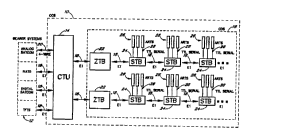
Figure I il}ustrates a block diagram of an exemplarv digital,
system in which the multi-nodal digital telephone riieiTihlTti~n system is ;.. l L .. ,t.. l
In the preferred ~ .. l.. ,l the multi-nodal digital telephone .I;~ - system is
S ;..llll.... n J in a f ~ l airplane for passenger use. In the ~ ' aircraft
cl.~..ul.lll.,llL, the overall digital ~ system is referred to as 8 cabin
system (CCS) 10, which is designed to prctvide igh quaiity voice and
data f ...... .~ ;... to, ~ ' aircraft passengers. The /u~ .t~c of the CCS 10
preferably cormects multiple voice snd fax/data chasnels to a plurality of
0 ICI,~ ~ 7/~ h ~ 7 12 on board the aircraft which establish a connection to
worldwide ~ ;11.. networks, or bearer systems utilizing the preferred
~ ..l.o.l; . .; of the telephone l1ietih~tinn system. Preferably, the CCS 10 provides
access to multiple bearer radio systems via the on board ICl.,..;~l;~h.. - ' ..- T' ~' 12 such
as a North American Telephone System ~NATS), Satellite T-' Systems
(SATCOM), and Terrestrial Flight Telephone Systems (TFIS). The CCS 10 preferablycompri~s a cabin i~' unit (CIIJ) 14 and a cabin d:~ ;l ;.... system
(CDS) 16. The CDS 16 provides the necessrry interfaces between each of the
telephone units used by the pas~ngers on the aircraft and the CTU 14. The CTU 14is an intelligent telephony switch that controls and routes telephone calls between the
passengers and the bearer systems 12.
The CTU 14 is a digita, telephony switching device which controls and routes
calls to and from the telephone units on the aircra* to one of the external bearer
systems. The CTU 14 ~ , Private Automatic Branch Exchange ~PAe,X)
r~ ;lY which is commonly used in multiple l;ne C~ teiephone
~ ~ - The CTU 14 provides thenecess~ry interfaces to, voice
and data 1".. ~.. : .. ~ from the internal aircraft telephone system to the external bearer
systems via a Primary Rate Interface (PRI~. Preferably, the CTU includes
u~ill~ly three to fifteen Counsel of European Posts and Telegraph (CEPT) El
PRI interfaces 18 to . with the ~ 12 of the digital bearer
systems, such as the NATS, digital SATCOM. and TFTS systems, and at least one
four-wire analog interface 20 to c.. , ~ with the analog 1~ of
~ W0~6/03846 i ~ 2195941 r~.,u~s/os~o
the analog bearer systerms, sudh as the analog SATCOM system.
As illustrated m Figure 1, the CDS preferably comprises at least one Zone
Telephony Box (ZTB) 22 and may comprise up to eight ZTBs. Each ZTB 22is
connected to the CTU 14 via a data link 18. In a preferred e l " t, each ZTB 22
S is connected to the CTU 14 via an El interface 18. Each ZTB 22is connected to at
least one telephony control unit, or Seat Telephony Box (STB)24 via a data link, such
as an El interface 18. In turn, each STB is connected to at least one Arrn Rest
Telephone (ART) 26 via a TTL serial com ection and analog, to the ear and
mouth pieces on the Imes 28. More preferably, up to three ARTs 26 can be connected
to each STB 24. Ad~ t. e~ ly~ utilizing the CDS 16 of the present invention an
ART 26 can be provided at every seat on the airplane. This enables a greater number
of passengers to have access for initiating telephone calls than many prior art systems.
In the preferred be " t, the ZTB 22, as illustrated in Figure 2, does not
include any telephony elc~,l" The telephony electronics are located on the STBs
24 and on the CTU 14. The ZTB 22is utilized for wire i amd power
~li~ih~hnn to the STBs 24 amd their respective ARTs (Figure 1). For wiring
Cv~ fi~ ,C the STBs24 are comnected in daisy chain loops to the ZTB 22. From theZTB 22, a loop 30is connected to a first STB 24 via an El interface
18; and in tum, the first STB 24is connected to a second STB 24 which is in turnconnected to a third STB24 which is in turn connected to further STBs24 umtil the end
of the chain is reached. At the last STB 24 in a chain, a loopback plug 32is provided
to comnect the outgoing transmit messages from the STB 24 to return wiring
in the STB 24. For cv..~, the return wiring is routed through each
of the STBs24 via the return wiring to the ZTB 30 and ultirnately to the
CTU 14. However, as will be understood by those of skill in the art instead of looping
the wiring through each of the STBs24 it is possible to connect the output of the last
STB 24 in each chain directly to the input of the CTU 14. However, in a typical
airplane C~l~;ll it is preferable to reduce the amount of wiring required, therefore
the loopback method is preferred over the direct connection of the last STB 24 in the
chain to the CTU 14.
Preferably, the ZTB 22 comprises up to four ~;1~1~11~1...1..~;11.1 Ioops 30 of STBs
Wo 96fO3846 1~ ' - 6 2 t ~ 5 9 4 I r~ Gi21b
24 which are indicated on Figure 2 as STB LOQP 0, STB LQOP 1, STB LQOP 2 and STBLoop 3. In the preferred ~ V ~ twenty STBS 24 may be comnected to STB
Loops O and 2 and twenty STBS 24 may be cormected to STB LOOPS 1~md 3; thus forty
STBS 24 are preferably connected to each ZTB 22. However, up to sixty four STB5
24 may be connected to and addressed by each ZTB. AS Will be recogni~ed by one of
skill in the art, additional STBS 24 may be added to each ZTB 22 by increasing the
number of address spaces reserved to address the ZTBS 22.
AS illustrated in Figure 2, it is possible to think of the ~ from the
CTU 14 to each of the STBS 24 and back to the CTU 14 as a single large IQOP which
is routed through the ZTB 22. In addition, the ZTB 22 transfers power from a power
supply 33 to each of the STBS 34 and their respective ARTS (Figure 1) Dlong a set of
power d;~ ' wires. With regard to power iictrih~ n, the ZTB 22 preferably
routes 115 VAC at 400 Hz from a power supply through the ZTB 22 to the STBS 24.
The STBS 24 in turn provide power to their respective ARTS. In an alternate
~.. l.U.ii~ power is provided directly to each of the STBs 24 from the airplane's
power supply. With regard to the between the CTU 14 and the STBS
24, an El i ~ (Tx) pair from the CTU 14 is preferably routed through the ZTB
22 along the dotted internal connection iine to STB Loop 0. In the preferred
t~ , tne power hnes are routed on a cable 34 which also contains the
.. "".. .: -~i,.. wiring. The STBS 24 in each of the STB IOOPS 3Q are configured in
a daisy chain, whereby the first STB 24 in STB LOOP O receives data on its receiver
(Rx) pair f rom the CTU's Tx pair 35;) and sends ciata to the next STB 24 in the loop
30 on its Tx pair ~to ihe next STB'S Rx patr). The last STB 24 in a IQOP has a
loopback plug 32 attached to it that routes the Tx pair coming from the last STB 24
2~ back through ail of the STBs 24 in the IDOP 30 on a return cable 36 through passive
c...,..~ on each STB 24. Once ~e Tx pair in STEi LDOP O is routed back to tbe
ZTB 22, it is cormected to the frst STB 24 in the next STB IOOP 30 via a cable 34.
The El 1,.... ,.. signal finally emerges from the last STB 24 in the last STB IOOP
30, such as STB LOOP 3. The last El i signal is routed back to the CTU
14 on the ZTB's Tx pair in a retnrn cable 36 to the CTl;i~s Rx pair 38. Therefore, in
order to enable proper connection of the STBS 24 to the CTiJ 14, if one of the STB
~ wo 96/03846 ~ 5 9 4 ~ 2 1 o
loops 30 on the ZTB 22 does not have any STBs 24 then a loopback plug 32 must beplaced on the ZTB to STB loop cormector to complete the El circuit.
As discussed above, a primary rate interface such as a CEPT El interface is usedto connect the CTU l4 through the ZTBs 22 to the STBs 24. The CEPT E1 interface
5 is based on utilizing two twisted p~urs of wires to connect two devices to each other
thus forn~ing a point-to-point interface. The clocking, and bit stream protocol for the
CEPT E1 interface is described in Re.,.. "... l~ .. G.703 of the lr
Telegraph & Telephone C~ ' ~., Committee (CCITT), as is well known to tbose
of skill in the art and is hereby ;A~ d by reference. The interface is run at 2048
Kilo-bits per second (Kbps). The bit stream is broken up into 32 channels, each
providing 64 Kbps throughput. Ofthe thirty-two channels available on the El interface,
a first charmel is used for framing the ~ , i.e., delimiting each frame. The
sixteenth channel on the E1 interface, also referred to as the D-channel, is utilized as
the signaling link between the CTU and each of the STBs to request and negotiate call
setup or call clearing and other signaling activities. The other thirty cha.-nels, referred
to as Bearer channels or B-charnels, are used as: linlcs to transfer voice,
voice-band data, and packet data from the ARTs to the CTU and ultimately to the
bearer systems. A.l~ ,,. v ~ly, by utilizing the E1 interface up to thnrty of the ARTs
may be utilized at the same time, because thirty B-channels are available to connect
telephone calls. This is a sigmficant advantage over the prior art systems whichenabled fewer telephone units wbich shared the same wiring to be operated at the same
time.
In order to keep track of the ~...,. - - - - - ;....S on tne D-channel, link access
protocol over the D-Channel (LAP-D) is utilized. As illustrated in
Figure 3, the traditional model for depiction of a ~ , protocol is to use a
"stack" model, where each logical layer of the protocol is shown as a "box"t with the
stacked on top of each other, from the bottom, up. The .,-- ,.". ~ protocol on
the D-channel is broken up into a plurality of layers, the first layer (L1) or physical
layer 44, the second layer (L2~ or the data link layer 44 and the third layer (L3) or the
network layer 46. As indicated above, the physical layer 44 is described by the CEPT
El standard, which is hereby ih~ ' by reference. In the preferred . .. ,ho.l;,,.. .,l
= ~
5 9 4 1
wos6~3s4~ 8 2 1 9 ~ 1&
the data link layer 45 of the protocol is described in the CCITT R~-.. l-~;,
Q.921, which is hereby i.l~vll ' by reference. Thc network layer of the preferred
is described in CCITT R~ - Q.931, which is hereby
;11~ VIIJVl~ by reference. The above protocol standards which have been ;... A ~by reference are well known to those of skill in the art. The collection of the CEPT El
physical layer 44, the Q.921 data link layer 45 and the Q.931 network.layer 46 is
sometimes referred to as the ISDN protocol. In addition to the standard portions of the
protocol, the STBs 24 include a soflware layer which enables severnl STBs 24 on a
loop to use the same physical medium to ~ with each other. This software
prograrn layer, which will be described in more detail later, is called a Medimn Access
Control (MAC) layer and provides the point tv multi-point ~ . . .L,. .- .1 of the telephone
~li~ih~lti~n system. As described bdow in association with Figure 6~ the MAC layer
is located between the physical layer and the data link layer. The MAC layer performs
the arbitration among all of the STBs 24 on the loop which want to use the D-channel
for signalling.
Figure 4 illustrates a block diagram of the clectronics rcsidcnt on each of the
STBs 24. The elcctronics provided on each STB 24 preferably comprises a Seat Powcr
Module (SPM) 40 and a Scat Telephony Modulc ~STM) 42. As described above,
power lines 48 and El i lines 18 are routed from the ZTB (Figure 2) to a
first STB in a loop. The power lincs 48 from the ZTB are routed to the SPM 40 which
converts the A/C power received from the ZTB to DC power. The SPM 40 routes the
DC power to the respective ARTs along line 50 and to the STM 42 along line 52. The
El lines 18 from the ZTB are routed to the STM 42. The STM 42
controls the telephony functions of the ARTs. Links are set up between each of the
ARTs to the STM 42 to transmit and receive voice ;,.r.. ~f; - data and command;.,r.. ,- ;.. tolfrom the ARTs along lines 62 and 64. Outgoing El d~da from the STM
42 on lines 68 as well as the power from the Seat Power Module 40 on lines 48 are
routed to an external connector on the STB 24 and are transmitted along lines 72, 48
lc~ ly to the next STB in the cham or to the CTU if the STB is the last module
30in the chain.
Figure 5 illustrates a more detailed functional block diagram of the hardware on
21 9594 1
~ wo 96103846 . ~ 18
the Seat Telephony Module (STM) 42. The El interf~e 18, i.e., the Rx t,.- ~"pairs 74 and the Tx 1~ , pairs 76, is connected to the STM 42 via a reiay 78.
The relay 78, when set, enables the El interface 18 to connect to the hardware of the
STM 42. However, if the STM 42 is not r, ..1:....~ properly or if it is desired to
disable the STM 42 functions for a group of users, the relay 78 can be opened and the
El 18 connection is terminatcd.
Assuming that the El interface 18 is connected through the reiay 78, the
i.,r.". ~;.". on the iRx pair 74 is received by El interface hardware 80. The Elinterface hardware 80 preferably comprises a framer 82 and an LIU 84. The input Rx
signal on the line 74 is transmitted first to the framer 82. The framer 82, typicaily a
crystai and associated logic, is utilized to dirfu.~ e~h of the charmels as they are
received from the El interface 18. The Rx signal is then transmitted to the LIU 84,
which converts the El signais from the voltage level required for E1 l~ to
a voltage level that is acceptable to the hardware in the STM 42. After the El interf~e
hardware 80 converts the bit stream received from the E1 interface 18 to signals that
are . ~ by the STM 42, the El interface hardware 80 sends the signals
received on the D-channel to the CEPT El transmit and receive (XCVR) hardware 85.
The CEPT XCVR 85 utilizes the High Level Data-link Control (HDLC) protocol, which
describes how to assemble a collection of octets, i.e., 8-bit values, to form a complete
HDLC message. The HDLC interiupt hardware acts in association with the XCVR 85
to interrupt a III;~.IUI./IV-,-~...Jl 86 when a complete message is received. Preferably, the
HDLC interrupt hardware is resident on the 1118,1U~/IU~,~,...,V~ 86. In the preferred
..,1 ~o~l .. ,.. ,l a Motorola 68302 IllI~lU~/lU~ )l which bas tne HDLC interrupt hardware
on the VIJI U~ DDVI is utilized.
Referring also to Figure 6, the CEPT XCVR 85 preferably comprises a receive
(Rx) queue 87 and a transmit (Tx) queue 88. The Rx queue 87 collects the data
received on the D-channel and groups the data into the HDLC message packet format
which is readable by a l.l;~,lU~JlU-,.,..~.Ji 86. The Tx queue 88 receives messages from
the ~liwvlJlu~aDvl 86 via the XCVR Tx queue service request routine (XCVR SQR)
89 and transfers the next available message m the Tx queuc 88 imto the .I~ lu~ e bit
stream format required by the t,.---- -l: ~ ... standard. Once a complete message has
2~ a~oA 1
W096/0384~ . r~."Ja. .c,~i& ~
been received by the Rx queue 87 on the CEPT XCVR 8~, an XCVR initiated HDLC
interrupt service routine (XCVR ISR) 90 is initiated. The MAC layer software 91
running on the ~ UlJIV~ ...Ul 8G determines if tne message received from the
D-channel is intended for this STM 42. If tbe message received by the STM 42 is
intended for the STM 42, the XCVR ISR 90 stores the message until the
IlI;~.lU~llU~.~.,vl 86 is avaiLable to act on the message. If the message receiYed is not
intended for this STM 42, &e XCVR ISR 90 on tne llllk.lU~lU.,~ .II 86 routes themessage to the XCVR SQR 91, for delivery to the Tx queue 88. The message is stored
in the Tx queue 88 until the D-channel becomes available. Once the D-charmel
becomes available, tbe message is sent through the LIU 84 and framer 82 im order to
adjust the voltage and clocking of the signal to the El standard of i and the
message is sent along Tx pairs 76 of the El 18 to the next STB.
The MAC lsyer 91 may be ~ Sd in at least two distinct operational
modes: the store-and-forward mode and the polling mode. In the preferred ~ _L
the MAC layer 90 is ,' ' in the store-and-forward operational msde. In the
stsre-and-forward mode, each STB 24 intercepts all D-channel messages. When a
complete HDLC me~sage is received by the XCVR RX queue 87, the XCVR intelrupt
service routine 90 is invoked ts move the message from the XCVR RX queue 87 to the
MAC layer queue 9t in the UIJIV~_..Ul. The intercepted message from the upstreamSTB 24 (closest ts the CTU) are looked at by the MAC layer 91. If the packet is a
broadcast message, ~i.e., if the message is sent to all of the STBs 24, the message is sent
to the L2 layer 92~ and a copy of the message is put back on the XCVR Th' queue 88
via the XCVR SQR 89 for ~ the du.. STB 24 (ts the next STB).
If the message is addressed to this STB 24, the MAC layer 91 sends it directly to the
L2 layer 92. If the message is not addressed ts this STB 24, it is put back into the TX
queue 88 via the XCVR SQR 89~ In all cases, the XCVR TX sueue 88 will remove
a message from the~head of the queue (least recent~ and send it out on the D-channel
once it is available. Therefore, in the store-and-forvard mode the messages on the D-
charmel will be delayed by each STB 24 for some period of time. Presently, the
~ delay caused by the STB 24 checking to see if the D-channel message is
intended for it and then passing the i"r.. A;"" onto the next STB 24 is 16 frames.
~1 ~594t
~ WO 96/03846 , ~ I / L ~, ', ~ 16
In an alternate ~ ' " t, the MAC layer 91 is . ' ' in tne polling
mode. In polling mode, tbe XCVR hardware 85 will "spy" on tbe D-channel by
~cf~nhlinz local copies of the messages received from an upstream STB 24, and
passing t. e D-channel bit stream through Imh~ r~ With each received message, aninterrupt will invoke the XCVR irterrupt serYice routine 90 which will send the
message to the MAC layer 91. The MAC layer 91 will look for a polling message
addressed to the STB 24. Any other message not addressed to this STB 24 is thrown
away. Once a polling message addressed to tbis STB 24 is received from the CTU 14,
the MAC layer 91 will instruct the XCVR hardware 85 to intercept all D-charmel
messages until further notice. It will also instruct the XCVR SQR 89 for the XCVR
TX queue 88 to commence its ~ operation for the next queued message.
While in this mode the MAC layer 91 will retransmit all messages from
upstream STBs 24 which are not addressed to tnis STB 24 by putting them on the
XCVR TX queue 88. If a broadcast message is received, it is copied and passed to L2
layer 92 as well as forwarded to the next STB 24. If the broadcast message received
is an order to go into store-and-forward mode by the CTU 14, then tbe MAC layer 91
will assume tbe Store and Forward mode until further notice. Otherwise, if a Polling
message addressed to another STB 24 is received, the MAC layer 91 instructs the
XCVR hardware 85 to go into "spy" mode, and instructs the XCVR SQR 89 for the
XCVR TX queue 88 to cease 1-~ g any more messages. In the poling mode, the
CTU 14 is constaDtly switching between each STB 24 as it polls for data. During the
time period that the STB 24 is polled, the STB 24 is constantly 1.~ ;..g its data
until the CTU 14 polls the next STB 24.
Regardless of the ultimate operational mode of the MAC layer 91, during the
system i" ~ ;"", the CTU 14 utilizes the store-and-forward mode to broadcast a
.~5;DhaLiull request to all the STBs 24. During the ~ ha~iul~ request, each STB 24
informs the CTU 14 that it is operable and where it is located on the loop. This is
~- - u.l.~ by each STBs 24 in turn sending their response to the 1~ tldtiUII request,
along with the responses from the other upstream STBs 24 to the CTU 14. Once hhel~g;.~ iUII is completed, all STBs 24 are assigned Terminating Endpoint Identifiers
(TEls), i.e., addresses on the loop. At this point, the MAC layer 91 will remain in the
95~94 1
w0 96/03846 12 , ~ .,r~
store-and-.~orward mode for tne remainder of the system operation, unless the CTU 14
indicates otherwise.
In order to enter the polling mode, the CTU 14 will broadcast a commence
polling message to all STBs 24. Thc MAC layer 91 will then instruct the XCVR
hard-vare 85 to only "spy" on the D-channel traffllc, as described above. The MAC
layer 91 v.~ill still assemble and send a copy of the received messages to thc XCVR RX
interrupt service routine 90, but it does this in parallel with other STB 24 vhich are
also listening to the D-channel. Also in polling mode, tbe XCVR service request
routine 89 for the TX queue 88 will be instructed not to send any other ;..f.
dun~ ~l to other STBs 24.
Regardless of the mode that the MAC layer 91 is operating m, if the mcssage
is intended for the STB 24, the STB 24 transfers the message to the link Q.921 L2 layer
92. Once the L2 layer 92 is available, the L2 layer 92 acts on the message. If the
message received by the L2 layer 92 also requires action by the Q.931 L3 layer 93, the
message is stored until the IlI;~lUJJlU~vUI 86 has the ~~ r to act on the Q.931
L3 layer 93 of the software. Once the L3 layer 93 be~aomes available, the L3 layer 93
acts on the mwsage. If the message received by the Q.931 L3 layer 93 also requires
action by the ~ ';.... layer (not shown), then the l.._lVIJ~U~....Ui 86 saves the
message until the r. ,~' Iayer is able to act on the message. Once the upper-most
layer has completed ~the required action on the message, if a response to the CTU 14
is required, the resp~se message is sent back down through the software layers until
the MAC layer 91 is reached. The message is received at the MAC layer 91 and sent
to the XCVR SQR 89 for i via the XCVR TX queue 88 to the El interface
18.
Referring back to Figure 5, in addition to the D-channel int~rf~rinf, the
fi~lu~Jlul.. J ~Ul 86 receives and transmits signals from the ARTs 26. Preferably, the
IIIIL~IU~/IU~ UI 86 is connected to each of the ARTs via a TTL UART 94. When a key
on the telephony keypad is depressed on the handset, the ART sends a signal to the
STB, which is received by the UART 94 on the ~TM 42. Once a s;gnal is received by
the UART 94, the UART 94 interrupts the Illl~lUylU~ UI 86 with a message in an
~ ASCII format from the ART. If the message received OD the UART 94 from the ART
~ w0 96~038~6 ~ 2 t 9 5 9 4 1 r~ c l j~ O
requires action by the CTU 14, such as a call initiation sequence or a call discoMect
signal, the Illi.,lUJJlU.,I,~Ol 86 processes the UART message and sends an ayl~
message to the CTU 14 on tbe D-channel, as indicated above. The additional hardware
on the STM 42 is preferably used to transmit voice and modem data from the ART 26
through the El interface 18 to the CTU. 14 Preferably, a c~d.,ld~cod~ . (CODEC) 95
is com~ected to each of the ARTs at one end and to a Time Division M~
(TDM) 85 at the other. Preferably, the CODEC 95 converts voice data, which is anaudio signal, to a digital signal that can be processed by the TDM 98. The CODEC 95
also converts the digital signals received from the TDM 98 to audio voice signals,
which are i ' to the ARTs. Preferably, the TDM 98 controls tbe receipt and
delivery of the voice data to/from the ARTs from/to the CTU 14. Further, a modem/fax
port on each ART is connected to a CODEC loop detector 96 for translating the analog
signals to digital signals and visa versa. The CODEC loop detector 96 is also
coMected to the TDM 98. Preferably, the TDM g8 is an Extended Phone Interface
Chip (EPIC~. such as a Siemens PEB-2055. Additionally, the UIJIU.,.,~JI 86 is
connected to external control logic 100, flash memory 101, and RAM memorv banks
102. F nally, the STM 42 includes passive wiring that routes the return signals, i.e.,
receive ('.'~) and transmit (Tx) p~urs 104, which are routed from the last STB in the
loop back to the ZTB. Therefore, the Rx pairs that are received by the STM 42 on the
return route are i " 'y routed to the Tx pairs on the STM 42 and then to the next
STB via the E1 interface. Ultimately, the message is routed back to the CTU.
When a call has been initiated, the CTU assigns one of the B-chaMels to the
STM 42 for i audio data to and from the ARTs. The CTU sends a message
on the D-channel to the STB indicating the chaMel ~ei~nm~nt The TDM 98 on the
STM 42 that initiated the call then activates a hardware connection between the
CODEC g5 assigned to the ART that initiated the call and the El interface hardware
80 in ~IC,.J~ t;UII for the receipt of the ~ from the assigned B-chaMel.
The E1 interf~e hardware 80 on the STM 42 monitors the signals l..~ . .1 on the
El interface 18 and looks for data on its assigned B-channel. Data bits on the
B-chaMels that are not assigned to the STM 42 are transmitted through the STB with
only a one frame delay which is caused by the El interface hardware 80 on the STM
W096/03846 ~ I =' i 14 L 3 ~ J ~
42 checking eûch B-channel as it passes through the STB to determine if thc channel
is assigned to this STB. As soon as the ;..r."...,.~ . is received by the STM 42 on thc
assigned B-channel, it is ' '~, converted to the proper format, i.e., voltage and
clock rate7 by the El interface hard vare 80 which can be received by the TDM 98.
The B-charmel ;.. r~.. - ;.. is routed through the TDM 98 to the uylJlu~ , CODEC
95 that is connected to the ART that initiated tho call. Preferably, the i..r .. ;.... on
the B-channel is routed tbrough the El interface hardware 807 the TDM 987 and the
CODEC 95 hardware to the ART without sigmficant delays. Vo;ce data received at the
ART is routed through the dedicated CODEC 95 to the TDM 98 and is i ' '
from the TDM 98 to the El interface hardware 80 for irnmediate connectiûn to thededicated B-channel for receipt by the CTU. By proving direct routing of the incoming
assigned B-channel signals through the hardware and by or ly ..lt.l~~ g the B-channel
for one clock cycle per STB to determine if the; r~ -7l, is intended for this STB,
the voice ;..rl- ...~ can be received and transmitted through the system without any
notable delay to the user.
Referring also to Figure 7, a ladder diagram is provided to illustrate an example
of the steps that occur from call initiation to call rrmr1~inn Typically7 the phone call
is initiated on the ARl' by a passenger who completes a series of initiation steps7 such
as pressing the on button7 entering a credit card number, etc. The initiation message
lû6 from the ART 26 is sent to the STB by signals received through the UART 94.
The UART 94 interrupts the llfi~ UV~I 86, which receives the call initiation
message 106 frûm ~e ART 26. The IllI~.lUlJlU~7vl 86 processes the
received from the ART 26 and transmits a phone call request message 108 to the
D-channel Tx queue on the CEPT XCVR 85. Once the D-channel becomes available,
the message from the CEPT XCVR 85 is transmitted through the LIU 84 and the
frarner 82 in order to adjust the voltage and clocking of the signal to the El standard
of 1l. .~... - ... The phone call request 108 is then sent on the D-channel from the
initiating STB 24 to the next Cul~.utin;; STB 24 on the El transmit (Tx) pair. The
next STB 24 reads in the message 108 on the D-channel through its receive (Rx) pair
of lines. The messa~e 108 on the D-channel is sent to the framer 82 and the LIU 84
to transfer the message to a voltage level and frequency that can be received by the
~ ~ 2195941
~ W096/03846 ' i ~ 5 r~,u,. ,~lX
STB 24. The message 108 is collected by the receiving queue on the CEPT XCVR 85.When a complete message has been received, the HDLC generates an interrupt to the
Illl~.IU~JIU~....Ol 86, which runs an interrupt service routine to decode the message 108.
Once it is determined that the message 108 is not destined for this STB 24, the
S Illh~lU~/lU~ aVI 86 sends the message lû8 to the transmit queue on the CEPT XCVR
85. Once the D-channel becomes available, the message 108 is sent through the LIU
84 and framer 82 and through the Tx pairs on the STB 24 to the next STB 24. Thisprocess of message checking by each STB 24 continues until the message is received
by the CTU 14.
The CTU 14 processes the initiate phone call request 108 and assigns one of the
B-channels as the t media for the call. In this example, the CTU 14 assigns
chalmel 17 to the call request of the initiating STB 24. The CTU 14 sends a message
on the D-channel to the first STB 24. As described above, the first STB 24 checks to
see if the message 110 on the D-channel is intended for its receipt. After the STB 24
determines that this message 110 is not intended for it, the first STB 24 sends the
message 110 out on the D-channel to the next STB 24. The message 110 traYels
through each of the STBs 24 until it reaches the requesting STB 24.
Once the message 110 reaches the initiating STB 24 on the D-channel, the
~II;-~IUI.IIU~ Vl 86 on the STB 24 determines the message 110 is intended for it. The
III;~.IUI~IU-~ 86 processes the message from the CTU 14 and determines that the
B-channel on charmel 17 is assigned to the call. The ll i~.lvl~lu.,C..~I 86 sends the
channel assignment ;"r~ 1;..., to the TDM 85. The TDM 85 sends a message to the
El interface hardware 80 indicating that all i..r~ received on channel 17 is to
be directly routed to the TDM 85. The TDM 85 in effect sets up a hardware
connection between the CODEC 95 assigned to the initiating ART 85 and tne El
interface hardware 80 m ~l~ ~dliuil for the receipt of the ~;.... , 8~ - ;..,. on charmel
17.
With this connection made, a message 112 is sent to the ART 26 to indicate a
call can be made on the assigned channel. Next, the passenger dials the requested
phone number 11-4. on the ART which is sent to the STB 24 via the TTL serial
interface. The phone number 114 is received by the UART 94 and is sent to the
- ~ 2~ 95~4
WO 96103846 ~6
III;~,IU~IU~ VI 86. The ~ V,U~V~.C~vl 86 trnnsfers the dialing; r-, X.." to tho
Q.931 software. The Q.931 sofiwaro sends tho dialing i .f~ . to the Q.921 layer.The Q.921 layor sends the dialing i.r,.". ;-- to the CEPT XCVR 85. From tho
XCVR 85 the data is sent to the El interfaco hardware 80 and then on the D-charmel
S of the El 18. As discussed abovo, tho phono number mcssago 116 from tho initiating
STB 24 is sent along tho loop to next subsequont STB 24, whoro it is A~tl~rmin~A~ that
tho messago 116 is not intended for that STB 24. The STB 24, in turn, sends the
messago 116 on to the other STBs 24 in the chain until it reaches the CTU 14. Once
the CTU 14 receives the phone number message 116, it establishes a connoction with
the external bearer system. Once the connection is made, the CTU 14 transmits the
connecting i.,r,.,.. ~;.... 118 on the D-charnel to the first STB 24, which passes the
connecting; f"..,-l;.... 118 on until the initiating STB 24 roceives the connection
i ,.rl,. ., - i ,., 118 on the D-channel.
The cormection i~ ;.... 118 received by the initiating STB 24, informs the
IS STB that the listenor can use tho assigned B-channol, i.o., channel 17. While the call
is connected, all voice and data j"c"", ;,~" 122 regarding the current call is sent to
from the ART 26 and through each Or the STBs 24 along the B channel, i.e., channel
17, to the CTU 14 and vice versa until thc call is A' .. -- .. '.. 1 However, as discussed
above, the STBs 24 that nre not assigned to the B-charmel ' ly reroute the
;, . r .. ", - .;". . on the B-channel to the next STB 24 and ever~ally to the CTU 14 causing
an i ~.g,.;r;.~." dolay in the ~ of the voice i ,f .. x,
After the c~ Liu-l has ended, the user initiates a terminate call sequence on
the ART 26; for example, the user presses the LND key on the handset. This
.,.. message 124 is sent on the TTL serial channel to the STB 24. The data is
received by the UA~.T 94 on the STB which interrupts tho Illl~IU~ .,JI 86. Tho
u. Vl".J~ -~" 86 procossos tho message 124 from tho ART 26. The IIII~IU~J~U~_..Jl
86 transmits a terrminate message 128 on the D-channel to the CTU 14. Tho mossago
128 is recoivod by oach of tho subsequent STBs 24. Once the STB 24 deterrnines that
the message 128 is not intended for it, it will pass the message 126 along the chain
until the message 126 is received by the CTU 14. Tho CTU 14 will terminate tho call
with the bearer system.
J3C,~ 21~941
~ W0 96J03X46 ~ r t7 ~ 2111
Next~ the CTIJ 14 sends a message 128 to the STB 24 indicating that the
reserved B-channel, i.e., channel i 7 in this case, is d ' and therefore available
for other users. The first STB 24 receives this message 128 and determines that the
message 128 is not intended for it. The STB 24 sends the message 128 to the nextSTB 24 in the chain. Once the initiating STB 24 receives the message 128, the
...;~ v~,.u ~ - .. 86 receives and process the message 128. The Illi~lU,UIU~ .JI 86 sends
a signal to the TDM 85 and to the El interface hardvvare 80, indicating that theecignmPnt of channel 17 to the STB 24 should be i ' The TDM 85 will break
the link between the CODEC 95 and the El interface 18 tbat was reserved fûr channel
17 l-.. .~.. .: . . .. ..~
Ad~ ~J.- ~l~, the CDS of the present invention reserves one of the
B-chamlels for each telephone Cu~ dtiul. that is initiated. By preventing other STB's
from il.t~,l.uluL,..g the voice 1.. .--..~ on the B channel for an extended length of
time I .y and unwanted delays in the voice, - are :" '
Further, by using a primary rate interface, such as an El ~ ; - . interface, the data
deliverv rate is fixed, so the voice ~ is delivered at a predictable rate. By
providing an interface vith a known data delivery rate, problems associated with;- delivery timesofvoice messages are eliminated. These l I
delays are common with other packet networks, such as Ethernet and Token Ring
systems. In additior., by ~" _ the number of devices that inte~upt the voice
unwanted delays, which cause difficulty in telephony . are
reduced to 1 t~ Ievels in the system. Other messages that are not a part of the
audio ~ul~ l~Lion are delivered along a separate data charmel, i.e., the D-channel,
which is i................. ~ulJk~ c~ However, such delays are generally acceptable in data delivery.
Further, the loop crnf~, ' of the Cabin Distribution System (CDS) reduces the
number of wires required to connect the telephony system of the present invention.
The present invention may be embodied in other specific forms without
departing from its spirit or essential cl.~t.,.;~Li.,~. The described c...l,o," are to
be considered in all respects only as illustrative and not restrictive. The scope of the
invention is, therefore, indicated by the appended claims rather than the foregoing
11, e~ipti~n All changes which come ~vithin the meaning and range of e.~LIivc.l~.ll.,~ of
W~ 96103846 ~ 1 ~ ';
18 ~ I r~J,,
the claims are to be embraced within ~eir scope.