Note : Les descriptions sont présentées dans la langue officielle dans laquelle elles ont été soumises.
CA 0222211~ 1997-11-24
W 096/38667 PCT~US96/O~?qO
HELICAL TURBINE FOR POWER AN~ PROPULSION SYSTEMS
FI~LD OF THE INVENTION
This invention relates to turbines and more particularly
to turbines capable of unidirectional rotation under
multidirectional fluid flows for use with hydro-pneumatic,
hydro, wind, or wave power systems.
BACKGROUND OF THE INVENTION
A unidirectional turbine is a turbine capable of
providing unidirectional rotation from bidirectional or
reversible fluid flow, such as in tidal estuaries or from
shifting wind directions. Generally, three basic types of
unidirectional reaction turbines are known, the Wells
= turbine, the McCormick turbine, and the Darrieus turbine.
The Wells reaction turbine is a propeller-type turbine
that comprises a series of rectangular airfoil-shaped blades
arranged concentrically to extend from a rotatable shaft, as
shown in Fig. 1. Typically, the turbine is mounted within
a channel that directs the fluid flow linearly along the axis
of the rotatable shaft. The blades are mounted to extend
radially from the rotatable shaft and rotate in a plane
perpendicular to the direction of fluid flow. Regardless of
the direction in which the fluid flows, the blades rotate in
the direction of the leading edge of the airfoils, which, in
Fig. 1, is counterclockwise.
The Wells turbine is capable of rapid rotation. The
~ outer ends of its blades move substantially faster than the
flowing air, causing high noise. Also, its efficiency is
relatively low, because the effective surface area of the
airfoil-shaped blades is limited to the outer tips, where the
linear velocity is greatest. The blades cannot capture a
substantial amount of the available energy in the fluid
CA 0222211~ 1997-11-24
W 096/38667 PCTrUS96/04340
flowing closer to the shaft.
The McCormick turbine comprises a series of V-shaped
rotor blades mounted concentrically between two series of
stator blades, as shown in Fig. 2. The rotor blades are
mounted for rotation in a plane perpendicular to the
direction of fluid flow. The stator blades direct fluid flow
to the rotor blades. To achieve unidirectional rotation with
bidirectional fluid flow, the outer stator blades are open
to fluid flowing from one direction, while the inner stator
blades are open to fluid flowing from the opposite direction.
The McCormick turbine is more quiet and could be more
efficient than the Wells turbine. However, its rotational
speed is too slow for direct operation of an electric
generator. Its configuration is also complex and expensive
to manufacture.
The Darrieus machine is a reaction turbine with straight
airfoil-shaped blades oriented transversely to the fluid flow
and parallel to the axis of rotation, as shown in Fig. 3.
The blades may be attached to the axis by circumferential end
plates, struts, or by other known means. In some variations,
the blades are curved to attach to the ends of the axis. A
Darrieus reaction turbine having straight rectangular blades,
mounted vertically or horizontally in a rectangular channel,
has been placed directly in a flowing body of water to
harness hydropower. The Darrieus turbine rotates with a
strong pulsation due to accelerations of its blades passing
through the higher pressure zones in the fluid that lowers
the efficiency of the turbine.
Thus, a need still exists for a quiet, efficient,
uniformly rotational, simple, unidirectional turbine that can
operate at high speeds.
SUMMARY OF THE INVENTION
The present invention provides a unidirectional helical
turbine capable of achieving high speeds needed for
industrial electric generators. The turbine comprises a
CA 0222211~ 1997~ 24
W U96138667 PCTAUS96~434
-- 3
working wheel having a plurality of airfoil-shaped helical
blades mounted transversely to the direction of fluid flow
for rotation in a plane parallel to the direction of fluid
flow. The blades extend between two supporting members, such
as a pair of parallel discs, mounted on a rotatable shaft.
The blades rotate in the direction of the leading edge of the
airfoil, regardless of the direction of fluid flow.
The helical configuration ensures that a portion of the
blades are always positioned optimally with respect to the
fluid flow, thereby creating maximum thrust to spin the
turbine. The continuous helical blades provide a continuous
speed of rotation uninterrupted by accelerations and
decelerations that accompany the Darrieus turbine as the
blades pass the least and most efficient thrust zones. The
skewed leading edges of the helical configuration further
reduce resistance to the turbine rotation. The helical
blades are operable with or without a channel to direct the
fluid flow.
In a further embodiment, a cylindrical distributor is
provided within the helical blades, to channel the fluid to
the blades of the turbine, thereby increasing the fluid
velocity near the blades and the power output of the helical
turbine. The helical turbine combined with the cylindrical
distributor attached to the turbine may also be used as an
apparatus for lifting or lowering bodies such as submarines
or submersible barges.
The helical turbine may also be provided with multiple
layers or rings of concentrically arranged helical blades.
The blades of adjacent rings are shifted circumferentially
such that they do not overlap each other in the fluid flow.
~ That is, the inner blades are positioned within the spaces
between the outer blades. The multilayer arrangement
~ increases the torque and power output.
In a case when the helical turbine is used with a
hydro-pneumatic energy converter, a channel interconnects a
pair of chambers in which air is alternately compressed and
CA 0222211~ 1997-11-24
W 096/38667 PCTrUS96/04340
expanded due to the alternate filling and emptying of the
chambers with water. The alternate compression and expansion
causes the air flow to alternate in direction through the
connecting channel. The helical turbine, mounted in the
channel, is in this manner able to capture the energy in the
flowing air and convert it to rotary mechanical energy. The
turbine is connected to an electric generator for generation
of electrical energy. No additional gearing speed increaser
is usually required, since the turbine rotates fast enough
for conventional generators.
In a hydro application, the helical turbine may be
mounted in a vessel located in a current of about 5 feet per
second or greater, such as in a tidal channel. The turbine
is located below the surface of the water, where the current
velocity is greatest, and is retained in that location by
virtue of the vessel's rise and fall with the water. The
helical turbine embodiment is particularly suited to this
application. A housing to channel the flow to the turbine
may by provided if desired, but is not necessary if the
current velocity is sufficiently great. The turbine is
connected to a suitable electric generator, which may be
mounted on the vessel in a water tight chamber. The turbine
can also be used in conventional applications, such as in
dams.
The helical turbine is also efficiently configured in
a modular form comprising, preferably, two or more helical
blades in spirals extending from one end to the other. For
wind power applications, a plurality of modules is arrayed,
vertically or horizontally, on rotatable shafts which are
supported by lightweight structures anchored to the ground
by guy wires. The optimally designed modules provide
unidirectional and uniform, non-oscillating rotation in any
non-zero angle between the turbine shaft and wind direction.
The helical turbine is also useful to provide propulsion
or supplement engine-driven propulsion of a marine vessel
utilizing the power of ocean waves. The helical turbine is
CA 0222211~ 1997-11-24
W 096138667 PCTrUS96104340
-- 5
operable under the multidirectional oscillations of ocean
waves and can develop a substantial axial torque useful in
~he propulsion of marine vesselsO
DESCRIPTION OF THE DRAWINGS
The invention will be more fully understood from t~e
following detailed description taken in conjunction with the
accompanying drawings in which:
Fig. 1 is a schematic illustration of a prior art Wells
turbine;
Fig. 2 is a schematic illustration of a prior art
McCormick turbine;
Fig. 3 is a schematic illustration of a prior art
Darrieus turbine;
Fig. 4 is a cross-sectional side view of a helical
turbine according to the present invention;
Fig. 5 is a frontal view of a helical turbine accordi~g
to the present invention;
Fig. 6 is a cross-sectional view along line VI-VI of
Fig. 5;
Fig. 7 is a cross-sectional view along line VII-VII of
Fig. 5;
Fig. 8 is a schematic cross-sectional side view of a
turbine according to the present invention illustrating zones
of thrust efficiency;
Fig. 9 is a fragmentary view of a single turbine blade
of the embodiment of Fig. 5 illustrating resolution of the
thrust force on the blade;
Fig. 10 is a schematic illustration of the turbine of
the present invention in operation in a hydro-pneumatic power
= ~ system;
Fig. 11 is a perspective view of a system mounted on a
catamaran for harnessing hydro energy according to the
present invention;
Fig. 12 is a frontal view of the system of Fig. 11;
Fig. 13 is a side view of the system of Fig. 11;
CA 0222211~ 1997-11-24
W 096/38667 PCTrUS96/04340
Fig. 14 is a schematic view of a helical turbine module
of a further embodiment of the present invention;
Fig. 15 is a schematic view of an array of the turbine
modules of Fig. 14 arranged vertically;
Fig. 16 is a schematic view of an array of the turbine
modules of Fig. 14 arranged horizontally;
Fig. 17 is a front view of a further embodiment of a
helical turbine of the present invention embodying a
cylindrical distributor;
Fig. 18 is a cross-sectional side view of the helical
turbine of Fig. 17;
Fig. 19 is a side view of a marine vessel propulsion
system of the present invention;
Fig. 20 is a front view of the propulsion system of Fig.
19; Fig. 21 is a schematic view of an array of turbines
connected via a transmission to a single generator;
Fig. 22 is a cross-sectional side view of a multilayer
helical turbine of the present invention;
Fig. 23 is a schematic front view of a multilayer
helical turbine of the present invention;
Fig. 24 is a schematic view of a helical turbine and
cylindrical distributor used to maintain flotation of a
submerged object by developing a lifting force;
Fig. 25 is an end view of the helical turbine and
submerged object of Fig. 24; and
Fig. 26 is a schematic view of a helical turbine as a
wind sail for a marine vessel.
PETAILED DESCRIPTION OF THE INVENTION
A helical turbine according to the present invention is
shown in Figs. 4, 5 and 14. The turbine 10 comprises a
plurality of airfoil-shaped helical turbine blades 12
supported for rotation on a rotatable shaft 14 by one or more
turbine blade support members 16. The airfoil-shaped blades
may be formed from any suitable material, such as a steel or
plastic material. The blade support members 16, which, in
CA 0222211~ 1997-11-24
W 096138667 PCTrUS96rO4340
the embodiment shown, comprise parallel, circular discs, are
fixedly mounted in spaced relation on the rotatable shaft 14
~ such that rotation of the blades 12 and discs 16 causes the
shaft 14 to rotate as well. The blades 12 are fixedly
S mounted to extend helically from one disc 16 to the other
disc 16 and are spaced radially from the rotatable shaft 14.
The blade support members may comprise other configurations,
cuch as a single central disc, radial spokes, or the likeO
The turbine 10 may be free in a fluid flow or may be
mounted inside a channel 20 or duct. The channel, if
provided, generally comprises opposed side walls 22,24, a top
wall 26, and a bottom wall 28 which form a passage 30 for
directing the flow of fluid to the turbine. The shaft 14 is
oriented transversely to the flow of fluid through the
channel and is mounted for rotation, for example, via
= bearings in the side walls of the channel. Also, with the
helical configuration, it is possible to eliminate the
channel entirely if desired.
Each helical blade 12 has an airfoil shape with a
leading edge 36 and a trailing edge 38 oriented transversely
to the flow of fluid. Preferably, the blades are formed with
a suitable airfoil profile, as is known in the art. The
blades 12 are mounted at the outermost diameter of the
circular discs 16 and are generally oriented to lie along a
circle defined by the outer diameter of the discs such that
the chord of each airfoil generally but not necessarily forms
the chord of an arc of the circle. Any number of blades may
be provided.
Referring to Fig. 4, fluid flowing in the direction of
arrows 40 along the channel 20 causes the turbine 10 to
rotate in the direction of the leading edge 36 of the blades
as shown by arrow 42. Similarly, fluid flowing in the
oppocite direction along the channel 20 also causes the
turbine to rotate in the same direction, the direction of the
leading edge 36 of the blades 12. As is apparent, the
turbine rotates in a plane parallel to the flow of fluid.
CA 0222211~ 1997-11-24
W O 96/38667 PCTrUS96/04340
The blades 12 should be spaced radially as far from the
rotatable shaft 14 as practicable to capture the greatest
amount of energy in the flowing fluid. The skewed leading
edges 36 further reduce resistance to the turbine rotation.
The helical blades may be divided into two halves 102a,
102b, as shown in Fig. 5, in which one half is a left-handed
helix and the other half is a right-handed helix. In this
manner, the components of the thrust force which extend
parallel to the shaft 14 cancel each other out, as discussed
further below. However, all left-handed or all right-handed
helixes or any other suitable helical configuration may be
provided if desired. The blades are fixedly attached at
their ends to extend transversely from one disc to the other
disc, creating a non-solid, fluid transmitting cylinder. In
addition, any suitable number of radial spokes 110 may be
provided which extend perpendicularly from the rotatable
shaft to each blade at spaced intervals. Such radial spokes
increase the integrity and structural strength of the system.
Alternatively, the blade support members may comprise other
configurations, such as a single central disc, radial spokes
alone, or the like.
In addition, a portion of the blades 12 are always
positioned in the most efficient zones of the fluid pressure,
thereby creating ~i~um thrust to spin the turbine. Two
least efficient thrust zones, near the top and bottom walls,
and a most efficient thrust zone, near the center, are
depicted in Fig. 8 merely for illustrative purposes. It will
be appreciated that in actuality the efficiency of the thrust
varies continuously from a minimum at the top to a maximum
at the midpoint to a minimum at the bottom, with no abrupt
break therebetween. In this manner, the blades rotate
continuously at a constant speed, without the accelerations
and decelerations which accompany turbines in which the
blades pass discontinuously through the most efficient and
least efficient thrust zones.
A resolution of the thrust force exerted on each blade
CA 0222211~ 1997-11-24
W 096/38667 PCTAUS~6fO~3~0
is illustrated in Fig. 9. The thrust A exerted on each blade
12 is perpendicular to the leading edge 36 of the blade. The
component B, perpendicular to the rotatable shaft 14, is the
working component of the thrust A, the component which pushes
the blade with respect to the shaft. The component C,
parallel to the rotatable shaft 14, exerts a force parallel
to the shaft on the shaft bearings. By providing two halves
with oppositely directed helixes, as shown in Fig. 5, these
components cancel each other out, thereby minimizing wear on
the shaft bearings. The angle y, the angle made by the
leading edge of the blade with respect to the shaft depends
on the particular application.
The helical turbine is particularly suitable for hydro
applications where strong water currents develop, and may be
installed on a vessel, as discussed further below, or in the
body of any low-head dam in a river. The helical turbine is
also suitable for harnessing wind and wave energy, as
discussed below.
In a further embodiment of the present invention shown
in Figs. 17 and 18, a distributor 206 comprising a generally
cylindrical tubular member is provided in the turbine between
the helical blades 202 and the shaft 214 to extend the length
of the turbine between the turbine supports 208. The
distributor 206 is disposed circumferentially about the shaft
214 and concentric with the helical blades 202. The
distributor 206 redirects the fluid streams inside the
turbine toward the outside rotating blades as indicated by
arrows 210, thereby increasing the fluid flow near the blades
and improving helical turbine efficiency and power output.
The distributor can be fixed to the shaft to rotate with the
~ blades (discussed further below) or it can remain motionless
with respect to the blades, for example by providing suitable
bearings between the distributor and support discs. If
mounted for rotation, the cylindrical distributor can be
mounted to rotate with the same angular velocity of the
blades or a different angular velocity, as would be known by
CA 0222211~ 1997-11-24
W 096/38667 PCTrUS96/04340
-- 10 --
those skilled in the art.
A small scale helical turbine was tested with and
without a distributor both in water and wind tunnels. The
turbine was made from an epoxy-type resin. The test results
indicate that turbine velocities and power output are
substantially improved with inclusion of the fluid
distributor. A more than double increase in efficiency can
be achieved in some applications compared with a turbine
without a distributor. Although shown in Fig. 17 with the
helical turbine of the present invention, the cylindrical
distributor can also be used with the Darrieus turbine.
As shown in Figs. 22 and 23, the helical turbine may
also be provided with multiple layers or rings 220, 222 of
concentrically arranged helical blades. Fig. 22 illustrates
two rings, each having three helical blades. Fig. 23
schematically illustrates two rings each having two helical
blades. Although two rings are shown, any suitable number
of rings may be provided. Similarly, any suitable number of
blades per ring may be provided. The spirals of blades of
adjacent rings may be, but are not necessarily shifted with
respect to each other to avoid shielding the inner blades by
the outer blades. The multilayer arrangement provides
greater torque and higher power. The multilayer helical
turbine is operable under the high water heads found in
conventional power plants, since the multiple rings increase
resistance to the water flow maintaining high water pressure.
The helical turbine of the present invention is shown
in Fig. lO in operation in association with a hydro-pneumatic
power generation system, such as that disclosed in U.S.
Patents Nos. 5,074,710 or 5,222,833. As generally described
above, the system comprises two water chambers 71, 72
interconnected by ingress and egress ports 73, 74, 75, 76 on
common shafts. As the water level 77, 78 in the two chambers
alternately rises and falls, air in the space above the water
level is alternately compressed and expanded. The air flows
through the channel 20 interconnecting the two chambers,
CA 0222211~ 1997-11-24
W ~96138667 PCTAUS96/O J~ tO
alternating directions in synchronism with the rising a~d
falling water levels.
The turbine 10 of the present invention is mounted
within the channel. The flowing air causes the turbine to
rotate as described above. When the flow of water through
the chambers reverses, the flow of air through the channel
also reverses. However, the turbine continues to rotate in
the same direction. During the air flow cycle, the air flo~s
in a first direction and the speed of the air increases ~o
a ~x; um.
The turbine is connected in any suitable manner to an
electric generator 79 for generating electricity. The
turbine can reach speeds of 1800 or 3600 rpm with water heads
of as low as one or two feet. Thus, the system is suitable
for generating power on rivers of small grades where high
dams are not applicable.
The helical turbine of the present invention may be
installed on a vessel 120, as shown in Figs. 11 through 13.
The vessel 120 rises and falls with the fluctuating water
level 122, ensuring that the turbine remains always at the
area of greatest velocity. A catamaran installation is shown
in Figs. 11 through 13, although any type of vessel or raft
may be used. A helical turbine 124 according to the present
invention, such as described in reference to any of the
embodiments described herein, is mounted to extend between
two pontoons or hulls 126, 128 of the catamaran and oriented
perpendicularly to the current flow, illustrated by arrows
130. The turbine 124 is mounted below the water's surface
122, so that all of the turbine is submerged. Water flowing
= 30 past the turbine blades 132 causes the blades 132 and shaft
134 to rotate, as discussed above.
Generally, the turbine is mounted either in a housing
136 having a turbine chamber such as described above or
without a housing. The housing, if employed, may have front
and back openings 138 therein to allow the current flow 130
to pass through the housing 136 and past the turbine blades
CA 0222211~ 1997-11-24
W O 96/38667 PCTrUS96/04340
132. The housing may be mounted to the pontoons 126, 128 in
any suitable manner. However, in some applications, such as
if the current velocity is sufficiently great, the housing
may not need to be provided. The shaft 134 may be connected
to an electric generator 140 in any suitable manner, such as
by a belted trAn~m;~cion 142. As shown, the electric
generator may be housed in a suitable water tight chamber 144
on the vessel if desired.
In a further embodiment, the helical turbine can be
efficiently configured as an optimal unit or module and
combined in a modular array to harness water or wind power.
The power available from a prior art propeller turbine is
proportional to the circumferential velocity of the blades,
which increases with distance from the turbine shaft. Thus,
prior art turbines are traditionally designed with a maximum
diameter. However, the size of such prior art turbines is
limited by their strength and possibility of structural
failures caused by centrifugal forces and vibrations when the
diameter becomes too large. The helical turbine is
advantageous in this regard, since its available power is
proportional to a frontal rectangular area equal to the
product of its diameter and its length, and the length is not
related to angular velocity or centrifugal forces. A
relatively small helical turbine module can be optimized for
airfoil profile, angular velocity, diameter, and length, and
an entire power system can be assembled from such modules.
Such a power system can exploit a common shaft and generator
for a number of modules and is simple to build and maintain.
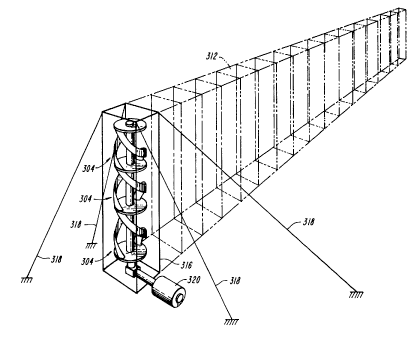
A suitable helical turbine module 304 is shown in Fig.
14. The module comprises one or more helical blades 302
arranged in a spiral about a central shaft 314. Generally,
at least two helical blades are used. The blades are
attached to a turbine support, such as one or more discs 308
or radial spokes, which is connected to the central shaft
314, as discussed above. Preferably, the blades are made
from a material which is strong and lightweight, such as
CA 0222211~ 1997-11-24
W ~96~38667 PCTAUS96/04340
aluminum or fiberglass, and may be hollow if desired.
Fig. 15 illustrates a turbine module 304 such as in Fig.
14 combined in an array for harnessing wind power, in which
the fluid flow can be multidirectional. The modules are
stacked vertically end to end. Preferably, the modules are
arranged with the direction of the spirals alternating, such
that one module is left handed and an adjacent module is
right handed. A plurality of vertically stacked modules are
arrayed adjacent to each other to provide a wall 312 of
turbine modules. Each vertical stack may be supported in any
suitable manner. For example, structural members may be
arranged to form a lightweight rectangular frame or truss
216, such as an antenna-type structure, around the vertical
stack and anchored to the ground by guy wires 318. Any
desired number of modules may be provided in any desired
number of vertical stacks. One or more electrical generators
320 are provided in communication with the vertical shafts.
A generator may be individually associated with each shaft,
or plural shafts may be connected via a suitable transmission
to a single generator, as shown in Fig. 21. The array of
modular turbines may be located in any suitable windy
location, as is known in the art, for example for locating
traditional windmill-type wind farms.
A further modular embodiment is shown in Fig. 16, in
which turbine modules 304 such as in Fig. 14 are arranged in
a horizontal configuration. A plurality of horizontally
disposed shafts 322 are arrayed vertically in a plane and
supported at their ends by suitable truss members arranged
to form a lightweight frame 324. The frames are anchored to
the ground with guy wires 326. A plurality of generators are
supported by the frames in communication with the shafts.
Any desired number of modules may be provided in any desired
number of rows. The rows may be of any desired length, and
any suitable number of frames may be provided to support the
desired length.
The array of modular helical turbines is advantageous
CA 0222211~ 1997-11-24
W O 96/38667 PCTrUS~610~10
- 14 -
since it exploits 100% of the rectangular swept cross-
sectional area of the blowing wind as well as being
self-starting. Traditional propeller-type wind turbines in
contrast, must be rotated to face the wind direction and
sweep a circular cross-sectional area. The helical turbines
provide a uniform non-oscillating rotation, as compared to
the prior art Darrieus turbines. The turbines provide
unidirectional rotation for any wind direction except
parallel or nearly parallel to the shaft, for which case no
or very little power can be developed. Also, birds are
likely to perceive the array of rotating helical turbines as
a solid wall, minimizing the danger of collisions, or the
turbine modules can be screened to prevent collisions with
birds. The modular system and lightweight frames provide for
structural strength and simplicity in assembly and
maintenance.
The modular helical turbines are useful in other
applications, such as in tidal straight or reversible water
currents with no dam construction, or in ultra low-head (less
then ten feet) hydropower plants, in, for example, rivers,
canals, or tidal estuaries. The modules can be used for
small power sources in ocean currents to supply lights or
other ocean electrical apparatus. In conventional power
plants, the modular helical turbine can be combined in long
chains or arrays, which is not possible with conventional
propeller type turbines.
The helical turbine of the present invention is also
useful to provide propulsion or supplement engine-driven
propulsion of a marine vessel utilizing the power of ocean
waves. The helical turbine is operable under the
multidirectional oscillations of ocean waves. Thus, the
helical turbine can develop an axial torque useful in the
propulsion of marine vessels.
As shown in Figs. 19 and 20, a helical turbine 400 as
described above is mounted along each side 402, 404 of a ship
406 below the water line 408. A propeller 410 is mounted in
CA 0222211~ 1997-11-24
W 09613~667 PCTAUS9G~
any suitable manner to the end of each turbine's shaft.
Although two turbines are shown, any number, including one,
could be used. The turbines provîde unidirectional rotation
independent of the directions of the waves' oscillations.
The turbines are aligned along the ship 406 to provide a
forward direction of motion. The longer the turbine's
length, the greater the amount of wave power that can be
harnessed. The length of the turbines are limited only by
the length of the ship.
The helical turbines 400 are beneficial as a propulsion
source or supplement, since they are not polluting, are
quiet, and conserve fuel required by the ship's engines.
~lso, the turbines stabilize the ship~s rocking by utilizing
the wave energy.
The helical turbine in a vertical orientation may also
be used as a wind sail for a ship. As shown in Fig. 26, a
suitable number of helical turbine modules 601 are attached
to the deck of a vessel 602 by a lightweight frame 603
anchored by guy wires 604. In this case, a suitable
transmission 605 for interconnection to a horizontal shaft
and propeller 606 are provided.
Lifting or lowering of an object in water can also be
accomplished with the helical turbine in combination with the
cylindrical distributor mounted for rotation with the turbine
shaft. The rotating cylinder develops a lifting or lowering
force depending on the direction of rotation. For example,
if the cylinder is rotating such that its upper surface is
moving in the direction of the current flow, the relative
velocity of the upper surface with respect to the current
flow increases and the pressure thereon decreases, while the
- relative velocity of the lower surface decreases and the
pressure thereon increases. Thus, a lift force is developed
on the cylinder. Similarly, if the cylinder rotates in the
opposite direction in the same direction of current flow, a
lowering force is developed on the cylinder.
Accordingly, relative to a flowing current of water, the
CA 0222211~ 1997-11-24
W 096/38667 PCTrUS96/04340
rotating cylinder, driven by the helical turbine, can be used
to raise or lower an object in water. No additional motor
is needed to rotate the cylinder. For example, as shown in
Figs. 24 and 25, a tug boat 501 dragging a plurality of
helical turbines 502 and cylinders 503 attached to the sides
of a submerged object such as a cargo barge 504 can be used
to maintain floatation of or tow the submersible barge
without an engine to drive the turbines. The barges can be
relatively long and large to hold large amounts of cargo and
can be larger than the tug boat.
The invention is not to be limited by what has been
particularly shown and described, except as indicated by the
appended claims.