Note : Les descriptions sont présentées dans la langue officielle dans laquelle elles ont été soumises.
CA 02373636 2001-11-09
WO 00/67641 PCT/US00/12877
-1-
SURGICAL CLAMP DEVICES ADD METHODS ESPECIALLY USEFUL IN
CARDIAC SURGERY
This application is related to U.S. Provisional Application Serial
No. 60/133,653, filed May 1 1, 1999, and claims the benefit thereof under
35 U.S.C. ~ 120.
Field of the Invention
The present invention generally relates to devices and methods
for performing surgical procedures involving vessels such as the aorta and,
more specifically, to clamping devices and methods particularly useful
during cardiac bypass surgery and other cardiovascular procedures that
involve temporarily arresting the heart.
Background of the Invention
During coronary artery bypass surgery, a surgeon bypasses an
obstructed artery by shunting or redirecting flow from a large vessel, such
as the aorta, to a part of the obstructed artery beyond the point of the
obstruction. A variety of conduits or tubes may be used as grafts to carry
this bypass blood flow. For example, the patient's own arteries and veins
may be harvested or other artificial conduits may form the bypass.
CA 02373636 2001-11-09
WO 00/67641 PCT/US00/12877
-2-
During a typical bypass procedure, or any procedure which
requires the heart to be stopped and placed on bypass such as Atrial Septal
Defect (ASD) repair or valve repair, the heart and lungs of the patient are
taken out of circulation by clamping the aorta and preventing retrograde
flow of blood through the aortic valve into the left ventricle of the heart.
Blood from the patient is redirected through a conventional heart-lung
machine. More specifically, the surgeon places an aortic cross-clamp
between the aortic valve and the first vessel of the aortic arch. While this
procedure prevents blood from entering the heart, it also prevents
oxygenated blood from perfusing the coronary arteries and thus places the
heart into cardiac arrest in a controlled manner. The heart like other organs
needs oxygenated blood to function when the blood supply is stopped to
any organ it will begin to necrose or die. In order to stop the heart to
repair
defects without allowing the muscle to necrose, a liquid solution was
developed called cardioplegia. Often, cardioplegia is administered between
the aortic clamp and the heart through a separate infusion cannula to
perfuse the arrested heart muscle. Cardioplegia is a liquid solution which
usually contains potassium and is designed to maintain viability of the
arrested heart muscle. If the aortic valve of the patient is functioning
properly, the valve will seal against this flow of cardioplegia and allow the
cardioplegia to enter the patient's coronary arteries surrounding the heart
muscle. The area of the aorta between the aortic valve and the first arch
vessel is a principle location for attaching proximal ends of the coronary
bypass grafts.
CA 02373636 2001-11-09
WO 00/67641 PCT/US00/12877
-3-
During heart surgery, the risk of stroke increases with the age
of the patient. At age 70 and above, the risk of stroke or brain disfunction
during surgery approaches about 15%. The cause of this problem is not
entirely clear, but increasing evidence suggests the occurrence of embolism,
or movement of dislodged plaque, from the aorta into the arch vessels and
on to the brain during heart surgery. Increasing evidence is implicating the
aortic cross-clamp in the production of embolic debris.
Many devices have been developed to trap dislodged plaque
debris before the debris is able to lodge in smaller arteries. For example,
surgeons deploy nets and filters in the arteries and veins to trap and remove
these emboli before they lodge in downstream arteries and vessels. Few
devices or improvements have been directed to reducing the root cause of
plaque dislodgment, there by reducing the risk of stroke. Plaque or calcium
deposits can be hard and brittle. These deposits occur naturally throughout
our life and form on the interior wall of many vessels, including the aorta.
The vessel wall being flexible can be manipulated with a rigid clamp to close
off the flow of blood by pinching the vessel between the flat jaws of an
aortic cross clamp. Cross clamps have been designed to pinch and grip the
slippery exterior surface of the vessel. However, if inflexible calcium
deposits are present under the clamp the squeezing of the aortic tissue can
these deposits the plaque.
Many types of clamps or intra-aortic balloon occlusion devices
have been developed and some attempt to reduce the amount of debris
created during aortic or other vessel clamping processes. As one measure
CA 02373636 2001-11-09
WO 00/67641 PCT/US00/12877
-4-
used to reduce the amount of trauma during a clamping operation, soft jaws
or pads have been used as exterior clamping surfaces. Unfortunately, even
soft jaws will fold and. severely compress the aorta. Therefore, dislodgment
of plaque remains inevitable. When the aorta is compressed flat to form the
necessary seal, the opposed aortic walls are parallel and therefore subject to
moderate compressive forces. Along these walls, the load spreads out over
a relatively large area with little elastic stretching of the tissue. However,
where the aortic wall turns 180° at each of the compressed corners or
folds
and the aortic tissue at those corners is subject to massive compression and
stretching forces. Plaque deposits at these corner locations, which may
include hard or soft calcium deposits, can easily fracture and dislodge from
the aortic wall.
Another type of clamping device, known generally as an intra-
aortic balloon which is placed by a femoral cannula, inflates within the aorta
to make full circumferential contact with the internal aortic wall surfaces.
Often, the balloon will stretch the aortic wall as it occludes the blood flow.
Like the external clamps, the balloon can dislodge hard or soft plaque from
the aortic wall. The balloon dislodges plaque by extending and separating
the soft flexible intimal lining of the aortic or vessel wall from the
inflexible
and often brittle plaque.
Due to various problems in the area of cardiovascular and
vascular procedures in general, and especially bypass procedures, it would
be desirable to provide clamping apparatus and methods designed to reduce
the occurrence of embolism during surgery. In addition, with existing
CA 02373636 2001-11-09
WO 00/67641 PCT/US00/12877
-5-
devices the surgeon must find physical space on the aorta to place three
separate components, i.e., the cardioplegia cannula, the cross clamp and
the aortic or bypass cannula. There is only a short distance of aortic vessel
between the aortic valve and the first arch vessel in which to make the
proximal graft connections, with three separate devices this valuable space
is used up with inefficient components. Therefore, a consolidation of the
hardware opens up space on the aortic vessel that can be used by the
surgeon to place graft vessels. Therefore, a long felt and unrealized need
must be addressed by efficiently combining components while reducing the
trauma to the vessel wall.
Still further, the surgeon must make incisions in the aorta for
both the aortic or bypass cannula and the cardioplegia cannula to gain
access to the interior of the vessel. Each of these incision sites must be
closed with sutures, such as purse string sutures when the cannulas are
removed. In addition to the time it takes to place the sutures and install the
cannulas each site is a prospective cause for leaks or tears in the aortic
wall. As well as breaking plaque from the aorta while sealing/suturing these
access sites. Further reduction of these risks is advantageous.
Summary of the Invention
In one aspect, the present invention provides a clamping device
for occluding a vessel during a surgical procedure. The clamping device
includes an internal core portion having a distal end with a sealing surface
and opposite side surfaces comprising sealing surfaces adapted to be
CA 02373636 2001-11-09
WO 00/67641 PCT/US00l12877
-6-
inserted transversely into the vessel through an incision in a wall of the
vessel. An external clamping portion is provided and extends on the outside
of the vessel. At least. one of the core portion and the external clamping
portion is movable with respect to the other to clamp the wall of the vessel
between the sealing surfaces of the internal core portion and the external
clamping portion. In accordance this aspect of the invention, the core
portion is movable relative to the external clamping portion to adjust the
length of the core portion within the vessel and to seat the distal sealing
surface of the core portion against a portion of the vessel wall generally
across from the incision. The distal sealing surface of the core portion is
preferably rounded to further prevent fracturing plaque during a clamping
procedure. The internal core portion and the external clamping portion may
extend substantially perpendicularly across the vessel or at other desirable
or necessary transverse angles across the vessel.
The external clamping portion is slidably movable along the
core portion in the preferred embodiment but other types of movement may
be used as well. The external clamping portion more specifically comprises
first and second pivotally connected vessel engagement arms. These arms
have clamping surfaces configured to receive and clamp the vessel and the
core portion therebetween when brought together to a clamped position.
At least one activating member and, more specifically, a pair of activating
members couple the arms together in the form of a scissor linkage which
moves the arms toward and away from one another and simultaneously
moves the core portion relatively longitudinally with respect to the arms. In
CA 02373636 2001-11-09
WO 00/67641 PCT/US00/12877
_7_
this manner, as the arms come together to a clamped position, the core
portion moves distally farther into the vessel preferably until the distal
sealing surface engages against the vessel wall generally across from the
incision. In the preferred embodiment, the arms move relatively proximally
back toward the core portion due to the action of a scissor linkage. The
activating members preferably comprise manually-operable members
configured to be squeezed together to facilitate this clamping and sealing
action both inside and outside the vessel. Respective connecting elements
on the first and second vessel engagement arms and the core portion
connect the arms to the core portion, preferably in a removable manner. In
the preferred embodiment, the connecting elements are C-shaped clips on
the activating members which receive respective bosses on the core portion
with a slight snap fit.
A ratchet mechanism is coupled with the vessel engagement
arms and locks the arms in a fixed position relative to one another and
further allows selective application of clamping pressure to the vessel. A
ratchet release is also provided for providing release of the clamping
pressure.
In another aspect of the invention, the core portion further
includes at least one lumen for delivering a fluid from outside the vessel to
within the vessel. More preferably, the core portion further includes two
lumens for separately delivering blood and cardioplegia fluid to opposite
sides of the core portion. These lumens may be separate cannulas
extending into the core portion or integrally formed hollow spaces in the
CA 02373636 2001-11-09
WO 00/67641 PCT/US00/12877
_g_
core portion or a combination of both as in the preferred embodiment. The
internal core portion may further include a valve mechanism for selectively
allowing fluid flow within the vessel between opposite sides of the internal
core portion. As examples, the valve may include a slide member or a
rotatable member used to regulate fluid flow.
The internal core portion preferably includes an inner portion
having a first hardness and an outer portion having a second hardness less
than the first hardness for contacting internal wall portions of the vessel.
The outer portion includes the opposite side surfaces of the core portion
which oppose sealing surfaces on the external clamping portion and include
the sealing surface at the distal end of the core portion. For example, al)
opposed sealing surfaces of the core portion and the vessel engagement
arms may be comprised of a soft polymeric material such as medical grade
foam.
In another aspect of the invention, the distal ends of the vessel
engagement arms are curved toward one another to present curved inner
clamping surfaces configured to engage an opposing, rounded outer surface
of the vessel across from the incision when the first and second vessel
engagement arms are clamped in position on the vessel. The distal ends of
the arms preferably include mating tips configured to engage one another in
the clamped position. The mating tips preferably provide a self-centering
action to longitudinally align the arms with each other in the clamped
position. Since the distal mating tips mate together, the vessel cannot
CA 02373636 2001-11-09
WO 00/67641 PCT/US00/12877
_g_
bulge outwardly at this location and leakage past the core portion in
therefore prevented at the distal end of the core portion.
As another aspect of the invention, a sealing member is
provided on the internal core portion and includes a sealing surface
configured to seal against the vessel within the incision. Preferably, the
sealing member is retained for movement along the internal core portion to
provide an adjustment feature depending, for example, on the size of the
vessel. The seal member is preferably retained on the core portion with a
dynamic seal, such as an O-ring, allowing sliding movement. At least one
seating surface extends on the sealing member for seating an adjustment
member, such as a sliding tube, associated with a purse string suture
applied around the incision. This feature allows the adjustment member or
tube to be pushed against the sealing member to hold the sealing member in
place within the incision. Typically, an adjustment tube associated with the
purse string suture is clamped in position after tightening. This action will
also fix the sealing member in its sealed position within the incision and
inhibit fluid leakage from the vessel.
As another optional manner of providing longitudinal movement
of the internal core portion, the core portion may be formed from a plurality
of sections with at least one section being longitudinally adjustable relative
to another to adjust the length of the core portion within the vessel.
A method of occluding the vessel in accordance with the
invention generally includes making an incision in a wall of the vessel;
inserting an internal core having a distal tip through the incision and into
the
CA 02373636 2001-11-09
WO 00/67641 PCT/iJS00/12877
-10-
vessel; moving the core into the vessel until the distal tip contacts an
interior portion of the vessel wall generally across from the incision;
placing
an external clamp on an exterior side of the vessel wall; and moving at least
one of the internal core and the external clamp toward the other to clamp
the vessel wall between the external clamp and opposite sides of the
internal core and between the distal tip of the core and the clamp.
The method can further include introducing fluid into the vessel
through the internal core and, more specifically, introducing first and second
fluids on opposite sides of the internal core. The moving step can further
comprise moving the interior core relative to the clamp into the vessel. The
method can further include engaging the wall of the vessel at the incision
with a seal member disposed on the internal core. The seal member may be
slid along the internal core and into the incision. After clamping, a valve
mechanism may be operated to regulate fluid flow from one side of the core
to the other.
These and other objects, advantages, and features of the
invention will become more readily apparent to those of ordinary skill in the
art upon review of the following detailed description of the preferred
embodiments, taken in conjunction with the accompanying drawings.
Brief Description of the Drawings
Figure 1 is a perspective view illustrating various elements of a
conventional bypass procedure.
CA 02373636 2001-11-09
WO 00/67641 PCT/US00/12877
-1 1
Figure 2 is a cross sectional view of the aorta and cross clamp
shown in Figure 1 schematically illustrating full clamping of the aorta with
the cross clamp.
Figure 3 is a fragmented cross sectional view showing the
aorta after the cross clamp has been released.
Figure 4 is a perspective view showing the installation of a
clamping and fluid introduction device constructed in accordance with the
invention preparing to be introduced into the aorta.
Figure 5 is a longitudinal cross sectional view of the clamping
and fluid introduction device with a core portion thereof being inserted into
the aorta.
Figure 6 is a fragmented, cross sectional view of the clamping
and fluid introduction device with the core portion fully inserted into the
aorta.
Figure 7 is a longitudinal cross sectional view of the clamping
and fluid introduction device in the fully inserted position and showing the
outer clamping members fully engaged with the outside of the aorta.
Figure 8 is a partially fragmented, cross sectional view taken
generally along line 8-8 of Figure 7.
Figure 9 is an exploded perspective view with the core portion
and outer clamping portion longitudinally sectioned to show various details
thereof.
Figure 9A is a partially fragmented, perspective view of the
distal tip of the core portion enlarged to show various details thereof.
CA 02373636 2001-11-09
WO 00/67641 PCT/US00/12877
-12-
Figure 10 is a perspective view of an alternative embodiment
illustrating a core portion with a slide valve.
Figure 1 1. is a cross sectional view taken generally along line
1 1-1 1 of Figure 10.
Figure 12 is a perspective view illustrating another alternative
core portion having a slide valve and a lengthwise adjustment feature.
Figure 13 is a perspective view illustrating another alternative
core portion having a rotatable butterfly valve.
Figure 14 is a cross sectional view taken along line 14-14 of
Figure 13 and showing the clamping device and core portion applied to the
aorta.
Detailed Description of the Preferred Embodiments
The present application is related to U.S. Provisional
Application Serial No. 60/133,653, the disclosure of which is hereby
incorporated by reference herein in its entirety.
In order to place a patient on a heart-lung machine to operate
on a non-beating or arrested heart, the surgeon must gain access to the
heart. Once the surgeon has opened the sternum and gained access to the
heart, the patient must be placed on the heart-lung machine. One must
first have a basic understanding of the circulatory system to understand the
bypass operation. The inferior and superior vena cava bring non-
oxygenated blood to the right atrium of the heart, which is essentially a
holding compartment. The non-oxygenated blood is then transferred into
CA 02373636 2001-11-09
WO 00/67641 PCT/US00/12877
-13-
the right ventricle of the heart, which is a pumping station. The non-
oxygenated blood is pumped from the right ventricle to the lungs for
oxygenation. Once the blood has been oxygenated in the lungs, it is
returned to the heart into the left atrium. Like the right atrium, the left
atrium is also a holding compartment. The oxygenated blood is then
transferred into the left ventricle. The left ventricle is/ a high-pressure
pump
that pumps the oxygenated blood into the ascending aorta, which carries
the blood throughout the body.
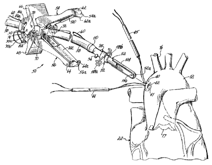
Referring to Figure 1, in a conventional bypass procedure or
any procedure that requires the surgeon to arrest the heart the surgeon will
place a cannula (not shown) into the right atrium to divert the non-
oxygenated blood flow from the body into the heart-lung machine. The
surgeon must create access for the blood to return to the body once it has
completed an oxygenation cycle in the heart-lung machine. Figure 1 shows
a purse string suture 10 in the ascending aorta 12 around the location of an
incision 14 just proximal to the first arch vessel 16. Incision 14 is located
between arch vessel 16 and aortic valve 17. The surgeon will make the
incision 14 within the boundary of the purse string suture 10. A bypass
cannula 18 is secured and sealed within incision 14 by purse string suture
10. This bypass cannula 18 returns oxygenated blood from the heart-lung
machine to the patient. As further shown in Figure 1, a conventional cross
clamp 20 is used between the bypass cannula 18 and the patient's heart
22. A second purse string suture 23 and cannula 24 is installed between
the cross clamp 20 and heart 22. Cannula 24 is used to administer
CA 02373636 2001-11-09
WO 00/67641 PCT/US00/12877
-14
cardioplegia to maintain the viability of heart 22 and includes a vent 26
used later for degassing the heart during start-up.
Figures 2 and 3 show how existing cross clamps 20 seal the
aorta 12. These clamps 20 force the internal or intimal wall surfaces 12a
of the aorta 12 together thereby preventing blood flow past clamp 20.
Plaque 30 at the apex 32 of the fold cracks and separates from the intimal
wall 12a of the aorta 12. As shown in Figure 2, aorta 12 deforms and
flattens in directions both parallel and transverse to its length. As Figure 3
shows, once the aorta 12 is opened by removing clamp 20, dislodged,
fractured plaque 30 is free to flow within the bloodstream 27 and
potentially to lodge in a smaller downstream vessels and cause an
embolism.
As Figure 4 illustrates, practicing the present invention will
preferably involve installing two purse string sutures 40, 41 about an
incision 42 in preparation for placing a patient on a heart-lung machine.
Two purse string sutures 40, 41 are used to provide a backup in case one
fails. As further illustrated in Figure 4, a two-part clamping device 50,
constructed in accordance with a preferred embodiment of the invention,
includes an elongate internal core portion 52 having a curved distal end
52a' having respective curved distal ends 54a, 56a shaped in a generally
complementary manner to distal end 52a of core portion 52 and external
clamping pieces 54, 56. The purse string sutures 40, 41 are used to seal
the aorta against core portion 52. When core portion 52 is removed, the
purse string sutures 40, 41 are used to permanently seal incision 42. It will
CA 02373636 2001-11-09
WO 00/67641 PCT/US00/12877
-15-
be appreciated that clamping device 50 preferably requires no additional
incisions or larger incisions other than those typically made during bypass
surgery. In this regard., and as detailed below, clamping device 50 can
include a bypass input cannula 58 and a cardioplegia (CP) input cannula 60.
Bypass input cannula 58 allows oxygenated blood to return to the patient's
aorta 12 from the heart-lung machine (not shown), while cardioplegia may
be administered to heart 22 on an opposite side of clamping device 50
through CP input cannula 60.
Referring now to Figures 4-9A, two-part clamping device 50
further includes a pair of vessel engagement arms 62, 64 each pivotally
connected to one another, as well as pivotally connected to respective
activating members 66, 68. More specifically, arms 62, 64 and activating
members 66, 68 are pivotally coupled in a scissor-linkage arrangement.
Arms 62, 64 are pivotally connected together at respective front pivots 70,
72 and activating members 66, 68 are pivotally connected together at
respective rear pivots 74, 76. A pair of upper pivots 78, 80 pivotally
connect arm 62 to activating member 66 and a pair of lower pivots 82, 84
pivotally connect arm 64 to activating member 68. For reasons to be
discussed below, and as apparent by reviewing Figure 5 in comparison to
Figure 7 respectively illustrating the open and closed positions of arms 62,
64, rear pivots 74, 76 will move in a forward direction toward the distal
ends 54a, 56a of clamping pieces 54, 56 and arms 62, 64 when activating
members 66, 68 are manually squeezed together by the surgeon.
Respective ratchet members 86, 88 extend from activating member 66 and
CA 02373636 2001-11-09
WO 00/67641 PCT/US00/12877
-16-
respective ratchet members 90, 92 extend in opposed relation to ratchet
members 86, 88 from activating member 68. Ratchet members 86, 88,
90, 92 have respective ratchet teeth 86a, 88a, 90a, 92a which engage as
shown in the figures to retain vessel engagement arms 62, 64 in the
clamped position shown in Figure 7. The distal tips 62a, 64a of arms 62,
64 are contoured as best shown in Figure 4 to provide a self-centering
action as arms 62, 64 are brought to the closed position shown in Figure 7.
Core portion 52 includes oppositely extending bosses 94, 95
which are received with C-shaped clips or retainers 97, 99 preferably with
a slight snap fit. A connector 1 10 is provided on core portion 52 for
connecting bypass cannula 58. A seal member 1 12 is slidably retained on
an outer surface of core portion 52 and slidably engages the outer surface
of the core portion 52 with an O-ring seal 1 14. Seal member 1 12 includes
a stepped-down portion 1 16 having an outer surface which sealingly
engages aorta 12 at incision 42 to inhibit fluid leakage from aorta 12 as
best shown in Figure 8. Seal member 1 12 includes oppositely extending
ears 1 18a, 1 18b having surfaces for seating respective tubes 44, 45 used
to tighten purse string sutures 40, 41 . Due to this feature, tubes 44, 48
may also be used to push against or retain seal member 1 12 within incision
42. For cushioning the clamping action of device 50 on aorta 12, a soft
cover 120, 122 is provided on each arm 62, 64 and an opposed cover 124
is provided on core portion 52 extending in opposed relation to linings 120,
122 on opposite side surfaces of core portion 52 and further covering the
distal tip of core portion 52 as shown in Figure 8. These covers 120, 122,
CA 02373636 2001-11-09
WO 00/67641 PCT/US00/12877
-17-
124 may be formed of any suitable medical grade, relatively soft material
such as foam, soft polymers, bladders, etc. In the preferred embodiment,
covers 120, 122, 124 are formed from closed cell foam, while the
remaining harder portions of core portion 52 and arms 62, 64 are molded
from polycarbonate. Thus, cushioning is provided at all clamping contact
points between the wall of aorta 12 and the respective inner surfaces of
arms 62, 64 and outer surfaces of core portion 52. Figure 9A shows that
core portion 52 is preferably injection molded and assembled from first and
second halves 126, 128 forming a hollow interior space 130. Ribs 132,
134, 136 are formed within hollow space 130 and function to evenly
distribute blood flow from bypass cannula 58 through an opening 144 in
core portion 52 and to prevent high blood flow impinging on and dislodging
plaque 30. The distal end of core portion 52 includes a recess 138 and a
mating boss 140 for connecting the two halves 126, 128 together. A
distal chamber 142 is formed in core portion 52 and includes an opening
146 for delivering cardioplegia to the opposite side of core portion 52
relative to opening 144. A wall 148 separates distal chamber 142 from
hollow space 130 and receives cardioplegia cannula 60 for the delivery of
cardioplegia. A retainer 150 is formed in hollow space 130 and retains
cardioplegia cannula 60 in place within hollow space 130.
Figures 10 and 1 1 illustrate an alternative core portion 160 as
another aspect of this invention. More specifically, core portion 160
includes a slide valve member 162 movable back-and-forth within core
portion 160 as designated by' arrow 163. Core portion 160 is usable in
CA 02373636 2001-11-09
WO 00/67641 PCT/US00/12877
-18-
conjunction with, for example, clamping device 50 with the outer clamping
pieces 54, 56 previously described, as shown in phantom lines. Slide valve
member 162 includes an actuating member 164 at a proximal or outer
position relative to the vessel being clamped and usable manually to push or
pull slide valve member 162. A bypass cannula 166 and a cardioplegia
cannula 168 are provided to respectively supply blood and cardioplegia fluid
to first and second internal spaces 160a, 160b within core portion 160.
Core portion 160 is used in generally the same manner to provide
cardioplegia and blood to the aorta, as described above, but slide valve
member 162 allows the surgeon to gradually restrict or increase blood flow
as opposed to immediately starting or stopping blood flow. This is
especially useful while placing a patient on a bypass or heart lung machine
or taking the patient off of the bypass or heart-lung machine. Core portion
160 is preferably formed from an inner hard layer and an outer softer layer
as previously described.
Figure 12 illustrates another alternative core portion 180
including a slide valve member 182 and an actuating member 184 as
generally described with respect to Figures 10 and 1 1. Core portion 180
may be used with clamping devices as generally described above, although
the clamping device has been deleted for clarity. A bypass cannula 186
and a cardioplegia cannula 188 provide blood and cardioplegia fluid to
internal sides of core portion 190 on either side of slide valve member 182
as in the embodiment of Figures 10 and 1 1. Also, the soft outer layer of
core portion 180 has been removed for clarity. The main difference
CA 02373636 2001-11-09
WO 00/67641 PCT/US00/12877
-19-
between core portion 180 and core portion 160 is that core portion 180 is
comprised of a first section 190 and a second section 192. Sections 190,
192 are connected for.lengthwise adjustment through recesses 190a, 192a
and bosses 190b (only one shown). This allows core portion 180 to be
length adjusted during insertion into a vessel, such as the aorta, and
thereby tailored to the size of a particular patient's vessel or aorta.
Figures 13 and 14 illustrate another alternative core portion
200 incorporating a butterfly valve member 202 which is rotatably actuated
by an actuating member 204. Actuating member 204 may then be
operated manually by a surgeon to gradually rotate butterfly valve member
202 between the closed position shown in solid lines in Figure 14 and the
full opened position shown in phantom lines. A blood inlet 206 and a
cardioplegia fluid inlet 208 are provided in core portion 200 to allow inflow
of blood and cardioplegia fluid on opposite sides of butterfly valve member
202 when in the closed position shown in Figure 14. This blood may be
introduced directly through actuating member 204 or through other suitable
conduits coupled with inlets 206, 208. Core portion 200 again preferably
comprises a hard inner layer 212 and a softer outer layer 210. Figure 14
further illustrates clamping pieces 54, 56 operating in conjunction with core
portion 200 similar to the previously described embodiments.
Operation
As shown in Figure 4, an incision 42 is first made in aorta 12
between the first arch vessel 16 and aortic valve 17. First and second
purse string sutures 44, 45 are placed about incision 42. Clamping and
CA 02373636 2001-11-09
WO 00/67641 PCT/US00/12877
-20-
fluid delivery device 50 is prepared and held in the open or unclamped
position shown with cannulas 58, 60 and core portion 52 extending
between arms 62, 64. In this position, padding 124 on core portion 52 will
oppose each padded surface 120, 122 of arms 62, 64. As shown in Figure
5, core portion 52 is inserted into aorta 12 through incision 42 until, as
shown in Figure 6, seal member 1 12 engages aorta 12 within incision 42.
Seal member 1 12 may be slid along core portion 52 until stepped portion
1 16 is fully contained within aorta 12. A seal is established between the
outer surface of stepped portion 1 16 such that fluid is inhibited from
leaking out of the interior of aorta 12 at this location. Also, O-ring 1 14
prevents fluid from leaking out of aorta 12 between core portion 52 and
seal member 1 12.
Figure 7 illustrates the fully clamped position of arms 62, 64
on the outside of aorta 12 and the position at which core portion 52 has
been fully inserted into aorta 12 until a distal sealing surface 52a engages
intimal wall 12a and any plaque 30, (illustrated schematically as a
continuous layer, although typically formed as separate deposits, at that
location). Padding 120, 122 along the inner surfaces of distal ends 54a,
56a directly opposes padding 124 at distal end 52a and lies on the outside
of aorta 12 as shown. This forms a gradual curved transition area, as
opposed to a sharp fold or apex, and inhibits the fracture of plaque in this
area. As activating members 66, 68 are squeezed together from the
position shown in Figure 5 to the position shown in Figure 7, C-shaped
retainers 97, 99 move in a forward direction and, therefore, push bosses
CA 02373636 2001-11-09
WO 00/67641 PCT/US00/12877
-21-
94, 95 also in a distal direction. This direction, as viewed in Figure 7 is to
the right. At the same time, forward pivots 70, 72 move proximally and
this pulls distal ends 54a, 54b toward distal end 52a for establishing a tight
seal. This is due to the scissor linkage action and distal movement of rear
pivots 74, 76 as activating members 66, 68 are squeezed together. As
members 66, 68 are squeezed together, ratchet teeth 86a, 90a and 88a,
92a engage one another to lock arms 62, 64 in the clamped position. To
release the arms, finger engagement portions 90b, 92b of ratchet members
90, 92 may be squeezed together to disengage the corresponding ratchet
teeth 90a, 92a from respective ratchet teeth 86a, 88a.
While clamping and fluid delivery device 50 is in the clamped
position, as shown in Figure 8, adjustment tubes 44, 45 of purse string
sutures 41, 40 are pushed in a distal direction and seat against ears 1 18a,
1 18b. This simultaneously tightens purse string sutures 40, 41 and pushes
seal member 1 12 completely within incision 42 to the sealed, fully engaged
position shown. At this stage, cardioplegia fluid may be administered
through cannula 60 and bypass blood may be input through cannula 58 and
into hollow space 130. Cardioplegia fluid will enter distal chamber 142 and
exit through opening 146 to flow into aorta 12 on one side of core portion
52, while blood will flow through opening 144 into the opposite side of
aorta 12 to circulate through the patient's body. Ribs 132, 134, 136 will
prevent the high pressure blood flow from impinging with great force on the
inner walls of aorta 12 and, therefore, functions as another manner of
reducing separation of plaque 30 from the inner wall of aorta 12.
CA 02373636 2001-11-09
WO 00/67641 PCT/US00/12877
-22-
When one of the embodiments shown in Figures 10-14 is
utilized, core portion 160, 190 or 200 may be used to regulate blood flow
to and from the heart,. especially during the procedures of placing the
patient on a heart-lung machine and taking the patient off of the heart-lung
machine.
While the present invention has been illustrated by a
description of a preferred embodiment and while this embodiment has been
described in some detail, it is not the intention of the Applicants to
restrict
or in any way limit the scope of the appended claims to such detail.
Additional advantages and modifications will readily appear to those skilled
in the art. The various features of the invention may be used alone or in
numerous combinations depending on the needs and preferences of the
user. This has been a description of the present invention, along with the
preferred methods of practicing the present invention as currently known.
However, the invention itself should only be defined by the appended
claims, wherein we claim: