Note : Les descriptions sont présentées dans la langue officielle dans laquelle elles ont été soumises.
CA 02424551 2003-04-23
STENT AND STENT-GRAFT
FOR TREATING BRANCHED VESSELS
BACKGROUND OF THE INVENT10N
Field of the Invention
The present invention is a radially self expanding stmt and stent-graft for
treating bifurcated
and other branched vessels of a patient, and methods for manufacturing and
implanting the stem
and stmt-graft.
Description of the Related Art
Medical prostheses frequently referred to as stems and stmt-grafts are well
known and
commercially available. These devices are used within body vessels of humans
and other animals
for a variety of medical applications. Stents and stem-grafts are, for
example, used to repair (i e.,
treat) abdominal aortic aneurysms. An abdominal aortic aneurysm is an enlarged
(i.e., dilated) and
weakened diseased area of the portion of the aorta between the renal artery
branch (i.e., the
location at which the renal arteries meet the aorta) and the iliac bifurcation
(i.e., the location
downstream from the renal artery branch at which the aorta branches or divides
into the iliac
arteries). Stenosis, a narrowing and occlusion of the aorta typically caused
by tissue buildup. also is
often present at these aneurysms- Aneurysms and stenosis at the carotid artery
bifurcation (i.e., the
location at which the common carotid artery branches into the internal carotid
artery and the
2 0 external carotid artery) are also treated with stents and stent-grafts.
The Parodi U.S. Patent 5,591,229 is directed to an aortic graft for repairing
an abdominal
aortic aneurysm. Briefly, the graft includes an elongated tube having first
and second ends, and
securing means for securing the first end of the tube to the aorta. The
securing means is an
expandable thin-walled member with a plurality of slots parallel to the
longitudinal axis of the
2 5 member. The thin-walled member is configured for delivery in an unexpanded
and undeformed
diameter state with an inflatable balloon within the member. After being
intraluminally delivered to
the site of the aneurysm, the balloon is inflated to radially extend the thin-
walled member to an
expanded and deformed diameter state. The first end of the thin-walled member
is thereby secured
to the aorta. Deflation of the balloon causes it to be disengaged from the
thin-walled member and
3 0 permits its withdrawal.
A graft for treating an aneurysm which extends above the renal arteries is
shown in Figure 7
of the Parodi patent. This graft includes a thin-walled securing member which
is interconnected to
70238-24D
CA 02424551 2003-04-23
the tube by at least one flexible connector member. The
flexible connector member spans the part of the aorta
adjacent the renal arteries so that blood flow through the
renal arteries is not obstructed.
There remains, however, a continuing need for
stems and stmt-grafts for treating branched vessels.
Improved stents and stmt--grafts for treating abdominal
aortic aneurysms and/or stenosis at the carotid artery
bifurcation would be especially useful. For example, stents
and stmt-grafts capable of remaining fixed within a
branched vessel as the diseased area of_ the vessel expands
would be desirable. Since accurately positioning a stmt
and stmt-graft in a branched vessel can be challenging, a
device of this type that can be relatively easily
repositioned would a7.so be desirable. In general, stem s
and stmt-grafts having different characteristics enable
medical personnel to select a device most suitable for the
treatment of the particular indication of the patient.
S~T1~2ARY OF THE INVENTION
The present invention provides a vascular gra:Et
adapted for placement in a primary blood vessel and suited
to bridge a vessel side branch, comprising: a tubular
structure defining an outer surface, a first portion of the
outer surface being sized to contact and support the blood
vessel on one side of the side branch, and a second portion
of the outer surface being sized to contact and support. the
blood vessel on the other side of the side branch, the
tubular structure defining an aperture for alignment wwth
the side branch so as to permit blood flow between the blood
vessel and the side branch;
-2-
70238-24D
CA 02424551 2003-04-23
wherein the first and second portions are separated across a
gap and further including at least one bridging member
traversing the gap and connecting the first and second
portions so as to prevent relative axial separation of th.e
two portions after implantation, the aperture being defined
between the bridging member and the first and second
portions.
The invention also provides a vascular graft
adapted for placement in a primary blood vessel and suitE~d
to bridge a vessel side branch, comprising: a tubular
structure defining an outer surface, a first portion of the
outer surface being sized to contact and support the blood
vessel on one side of: the side branch, and a second portion
of the outer surface being sized to contact and support the
blood vessel on the other. side of the side branch, the
tubular structure defining an aperture for alignment wi.t:h
the side branch so as to permit blood flow between the blood
vessel and the side branch; wherein the tubular structure
comprises a flexible graft body and a support stmt, and
wherein the flexible graft body is only provided in one of
the first. or second portions, the other portion being
defined solely by the stmt.
The invention further provides a vascular graft
adapted for placement in a primary blood vessel and suited
to bridge a vessel ride branch, comprising: a first tubular
structure sized to contact and support the blood vessel on
one side of the side branch; a second tubular structure
sized to contact and support the blood vessel on the other
side of the side branch; and at least one bridging member
connecting the first and second tubular structures so as to
-2a-
7 0 2 3 8 - 2 4 D ~ 02424551 2003-04-23
define an aperture in the vascular graft sized for blood t:o
flow through between the blood vessel and the side branch,,
wherein at least one of the first and second tubular
structures comprises a flexible graft body and a support
stmt, and wherein the flexible graft body is only provided
in one of the first or second tubular structures, the other
tubular structure being defined solely by the stmt.
-2b-
CA 02424551 2003-04-23
BRIEF DESCRIPTION OF THE DRAWINGS
Figure 1 is an ivustration of a portion of an aorta in which stents and stent-
grafts in
accordance with the present invention can be implanted.
Figure 2 is an illustration of a stent in accordance with a first embodiment
of the present
mvent~on.
Figure 3 is a detailed illustration of a portion of the stent shown in Figure
2, showing one of
the filaments of the renal artery branch section wound around a filament of
the fixation section-
Figure 4 is an illustration of the stent shown in Figure 2 after implantation
in the portion of
the aorta shown in Figure 1.
Figure 5 is an illustration of a stent in accordance with a second embodiment
of the present
invention.
Figure 6 is an illustration of a stmt in accordance with a third embodiment of
the present
invention.
Figure 7 is an illustration of a stmt-graft in accordance with a fourth
embodiment of the
present mvent~on.
Figure 8 is an ivustration of a stem-graft in accordance with a fifth
embodiment of the
present mvent~on.
Figure 9 is an illustration of a stmt-graft in accordance with a sixth
embodiment of the
present invention.
2 0 Figure 10 is an illustration of a portion of a carotid artery in which
stems and stent-grafts in
accordance with the present invention can be implanted.
Figure 11 is an illustration of a stent-graft in accordance with a seventh
embodiment of the
present invention.
Figure 12 is an illustration of the stent-graft shown in Figure 11 after
implantation in the
2 5 portion of the carotid artery shown in Figure 10.
Figure 13 is an illustration of a stent-graft in accordance with an eighth
embodiment of the
present invention.
DETAILED DESCRIPTION OF THE PREFERRED EMBODIMENTS
3 0 Figure 1 is an illustration of a section of a diseased abdominal aorta 12
which can be treated
by the aortic stmt and stent-graft of the present invention. As shown, renal
arteries 14A and 14B
extend from the aorta 12 at renal artery branch 16. Downstream from (i.e., on
a first side of) the
renal artery branch 16 is the iliac bifiucation 20 at which the aorta 12
divides (i.e., branches) into
-3-
CA 02424551 2003-04-23
iliac arteries 18A and 18B. The stent and stent-graft of the present invention
can be used to treat a
diseased portion 26 of the aorta 12 which is located between the renal artery
branch 16 and the iliac
bifurcation 20. The diseased portion 26 is represented in Figure 1 by an
aneurysm (i.e., a weakened
and expanded-diameter section). Although not shown in Figure l, the aneurysm
or other disease
attributes (i.e., indications) of the aorta 12 being treated can extend all
the way to the renal arteries
14A and 14B, andlor beyond the iliac bifurcation 20 into the iliac arteries
18A and/or 18B. .As
described in greater detail below, the stent and stent-graft of the present
invention can make use of
a portion 24 of the aorta 12 which is typically relatively healthy, and
located upstream from the
renal artery branch 16 (i.e., on a second side of the renal artery branch and
opposite the branch
from the diseased portion 26). Arrows 22 are included in Figure 1 to
illustrate the direction of
blood flow through the aorta 12, renal arteries 14A and 14B and iliac arteries
18A and 18B.
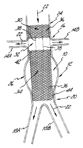
' Aortic stmt 10, a first embodiment of the present invention, is shown in
Figure 2. Stent 10
is a tubular device and includes an upstream or fixation section 30, renal
artery branch section 32
and downstream or diseased aorta section 34. Fixation section 30 and diseased
aorta section 34 are
formed from two sets of oppositely-directed, parallel, spaced-apart and
helically wound elongated
strands or filaments 36. The sets of filaments 36 are interwoven in an over
and under braided
configuration intersecting at points to form an open mesh or weave
construction. Methods for
fabricating stent structures such as fixation section 30 and diseased aorta
section 34 are generally
known and disclosed, for example, in the Wallsten U. S. Patent 4,655,771 and
the Wallsten et al.
2 0 U.S. Patent 5,061,275. In the embodiment of stent 10 shown in Figure 2,
the fixation section 30
and diseased aorta section 34 are formed from structures which are
substantially similar vrith the
exception of their length. Other embodiments of the invention described below
include fixation and
diseased aorta sections which are formed from stent structures having
different characteristics.
Renal artery branch section 32 is formed by filaments 38 which have their
opposite ends 40
2 5 connected to filaments 36 of the fixation section 30 and diseased aorta
section 34. Six filaments 38
(only four are visible) which are parallel to the longitudinal axis and
equally spaced aromd the
circumference of the stem 10 are shown in Figure 2. As perhaps best shown in
Figure 3, the
opposite ends 40 of the filaments 38 are connected to the fixation section 30
and diseased aorta
section 34 by being wound around the filaments 36 of the fixation and diseased
aorta sections. The
3 0 ends 40 of the wound filaments 38 can extend at an acute angle with
respect to a longitudinal axis
of the stmt 10, and toward the diseased aorta section 34, to form a barb which
can help anchor the
stent 10 to the aorta 12 or other vessel in which the stent is implanted. In
other embodiments (not
shown) the filaments 38 of the renal artery branch section 32 can be attached
to the fixation section
-4-
CA 02424551 2003-04-23
30 and diseased aorta section 34 by other known or methods such as welding. As
is evident from
Figure 2, the porosity of the renal artery branch section 32 is greater that
that of the fixation section
30 and the diseased aorta section 34 (i.e., the density of the filaments 36 in
the fixation and dis~"ased
aorta sections is greater than the density of the filaments 30 in the renal
artery branch section).
Stent 10 is shown in its expanded or relaxed state in Figure 2, i.e., in the
configuration it
assumes when subjected to no external loads or stresses. The filaments 36 are
resilient, perntitting
the radial compression of the fixation section 30 and diseased aorta section
34 of stent 10 into a
reduced-radius, extended-length configuration or state. The renal artery
branch section 32 can also
be radially compressed into a reduced-radius configuration or state along with
the fixation sec,~tion
Z 0 30 and diseased aorta section 34, thereby rendering the stent 10 suitable
for delivery to the diseased
aorta treatment site through a body vessel (i.e., transluminally). Stent 10 is
also self-expandable
from the compressed state, and axially flexible.
A wide variety of materials can be used for the self expanding stent filaments
36 and 38.
Commonly used materials include Elgiloy~ and Phynox~ spring alloys. Elgiloy~
alloy is available
from Carpenter Technology Corporation of Reading Pennsylvania- Phynox~ alloy
is available from
Metal Imphy of Imphy, France. Other materials used for self expanding stmt
filaments 36 and 38
are 316 stainless steel and MP3 SN alloy which are available from Carpenter
Technology
Corporation and Latrobe Steel Company of Latrobe, Pennsylvania, and
superelastic N~tinol alloy
which is available from Shape Memory Applications of Santa Clara, California.
2 0 Conventional or otherwise known devices for delivering self expanding
stems can be used
to deliver stent 10 to a diseased aorta 12. Delivery devices of these types
are, for example,
disclosed in the Wallsten et al. U.S. Patent 4,732, I 52, Burton et al. U_S.
Patent 5,026,377., Heyn et
al. U.5. Patent 5,201,757, and Braunschweiler et al. U.S. Patent 5,484,444.
Briefly, the delivery
devices (not shown) can include an elongated and flexible inner tube having
proximal and distal
2 5 ends. The stent I 0 is forced into its reduced-radius compressed state
around the distal end of the
inner tube, and constrained in the compressed state by an outer tube which
surrounds the inner tube
and stmt 10. A deployment mechanism which can be actuated from the proximal
end of the
delivery device retracts the outer tube with respect to the inner tube,
thereby allowing the stmt 10
to self expand into engagement with the inner wall of the aorta 12.
3 0 The assembled delivery device is inserted percutaneously into the femoral
artery and
directed through the artery until the distal end with the constrained stent I
O is positioned at the
diseased portion 26 of the aorta 12. The deployment mechanism is then actuated
to allow the stent
I 0 to self expand into engagement with the aorta 12. Figure 4 is an
illustration of the stmt 10
CA 02424551 2003-04-23
implanted into the aorta 12 shown in Figure l . As shown, fixation section 30
is located at and
engaged with the relatively healthy portion 24 of the aorta 12 immediately
opposite the renal
arteries 14A and 14B from the iliac branch 20 Renal artery branch section 32
is located at the
renal artery branch 16 and extends across the locations at which the renal
arteries 14A and 14B
open into the aorta 12. The diseased aorta section 34 of the stmt 10 extends
across the diseased
portion 26 of the aorta 12, and therefore provides additional strength for
this vessel. In a similar
manner, the support provided by diseased aorta section 34 can help maintain a
diseased aorta open
in the presence of stenosis (not shown in Figures 1 and 2) which would
otherwise reduce the blood
flow capabilities of the vessel.
In the embodiment shown in Figure 4, the diseased aorta section 34 of stent 14
extends
from a location immediately downstream from the renal arteries 14A and 14B to
a location
immediately adjacent to the iliac arteries 18A and 18B. A first end 42 of the
diseased aorta section
34 adjacent to the renal artery branch section 32 is expanded radially
outwardly into engagement
with the inner walls of the aorta 12 adjacent to the renal arteries 14A and
14B. A second end 44 of
the diseased aorta section 36 is expanded radially outwardly into engagement
with the inner walls
of the aorta 12 adjacent to the location at which the iliac arteries I 8A and
18B intersect the aorta.
As shown, the diseased portion 26 of aorta 12 between the portions at which
ends 42 and 44 of the
section 34 engage the aorta (i_e., the aneurysm) is weakened and extends
outwardly beyond the
stmt I0. Under this and other similar conditions the amount of anchoring
support provided by the
2 0 relatively small surface area engagement of the ends 42 and 44 with the
diseased portion 26 of the
aorta 12 may not be su~cient to securely maintain the stent section 34 in its
implanted position.
Fixation section 30 of the stmt 10, through its engagement with the relatively
healthy
portion 24 of the aorta 12 and its interconnection to the diseased aorta
section 34 by filaments 38,
provides substantial anchoring support for the diseased aorta section. The
fixation section 30
2 5 thereby enhances the positional stability of the implanted diseased aorta
section 34. This enhanced
positional stability is achieved without substantially restricting blood flow
to the renal arteries 14A
and 14B since the material density of the renal artery branch section 34
(i.e., the density of filaments
38 of stent 10) is relatively low. As used in this document, the term
"porosity' also refers to the
density or spacing of the filaments 38 (e.g., the amount of open space between
the filaments with
3 0 respect to the amount of space occupied by the filaments). Additional
anchoring support for the
stent 10 is provided by the barbed-type ends 40 offilaments 38 which engage
the interior wall of
the aorta 12.
-b-
CA 02424551 2003-04-23
A stmt 10 for implantation in the aorta 12 of an average size adult patient
can be between
about 5 cm and 15 cm in length and have an expanded state diameter between
about 2 cm and 5
cm. The fixation section 30 can be between about 1 cm and 5 cm in length. The
renal artery
branch section 32 can be between about 1 cm and 5 cm in length. The diseased
aorta section :34
can be between about 4 cm and 15 cm in length. These dimensional ranges can of
course be larger
and smaller to accommodate the anatomy of larger and smaller patients.
Features and characteristics of the fixation section 30 can be varied to
change the amount
of anchoring support being provided. For example, the amount of anchoring
support will increase
with increasing length of the fixation section 30 (due to increased surface
area of engagement), with
l0 increasing braid angle 8 of filaments 36 (illustrated in Figure 2, due to
increased radial force
generated by the section), and with increasing diameter (e.g., an outwardly
flared end) and/or
stiffness of filaments 36 (due to increased radial force of the section).
Conversely, these and other
characteristics of the fixation section can be decreased or otherwise varied
to decrease the amount
of anchoring support provided by the fixation section 30. The force exerted by
the fixation :>ection
1 S 30 on the aorta, and therefore the amount of anchoring support being
provided, is the summation
of the radial pressure exerted over the surface area of the section. The
amount of anchoring
support can therefore be varied by changing the radial pressure and surface
area characteristics of
the fixation section 30.
The amount of anchoring support to be provided by the fixation section 30, and
the:
2 0 features and characteristics of the fixation section to provide the
support, can be optimized and
selected to suit the indications of the particular diseased aorta 12 in which
the stent 10 is to be
implanted. For example, the relative amount of anchoring support to be
provided by the fixation
section 30 will often depend upon the amount of positional support that the
diseased aorta section
34 is capable of generating in connection with the aorta 12 in which it is
implanted. In the example
2 5 shown in Figure 4, for example, the diseased aorta section 34 generates at
least some anchoring
support where its ends 42 and 44 engage the aorta 12. Diseased aortas that are
relatively more or
less healthy than that shown at 12 in Figure 4 may be suitable for use with
stents 10 having a
fixation section 30 which provides less or more anchoring support,
respectively, than the fixation
section shown in Figure 4. The manner by which the fixation section 30 is
configured to 'provide
3 0 the desired amount of anchoring support can depend on the nature (e.g.,
relative health) of the
portion 24 of the aorta 12 in which the fixation section is to be implanted.
For example, if the
portion 24 of aorta 12 in which the fixation section 30 is to be implanted is
relatively weak, it may
_,_
CA 02424551 2003-04-23
be advantageous to provide a fixation section which generates relatively low
radial forces, but
which is relatively long to achieve the desired anchoring support.
Stent 210, a second embodiment of the present invention, is illustrated in
Figure 5.
Features of stent 210 which are similar to those of scent 10 shown in Figure 2
are indicated by like
reference numbers, and have similar characteristics. As shown, the stent 210
includes fixation
section 230. renal artery branch section 232 and diseased aorta section 234.
Sections 230, 232 and
234 are all formed from self expanding, braided filament stmt structures of
the type described
above. Stent 210 can be manufactured from a unitary braided filament stent
structure by cutting
and removing selected filaments from the portion of the structure to form the
renal artery branch
section 232. The density of the braided filaments 236 in the renal artery
branch section 232 is
thereby reduced from the density of the filaments in the fixation section 230
and the diseased aorta
section 234. By way of example, stents such as 210 can be formed from thirty-
eight to ninety-six
filaments 236 (each of which is an individual wire andlor a pair of wires),
with fifty to seventy-five
percent of these filaments being cut and removed from the original structure
to form the renal artery
branch section 232. Stent 210 can be implanted in a manner similar to that of
stent 10 and
described above.
Stent 310, a third embodiment of the present invention, is illustrated in
Figure 6. Features
of stent 310 which are similar to those of stent 10 shown in Figure 2 are
indicated by like reference
numbers, and will have similar characteristics. As shown, the stmt 310
includes fixation s~tion
2 0 330, renal artery branch section 332 and diseased aorta section 334.
Sections 330, 332 and 334 are
all for7ned from self expanding, braided filament stem structures of the type
described above. The
braid angle 8 of the filaments 336 (and therefore the density and radial
force)of the fixation section
330 is Beater than the braid angle 8 of the filaments in the renal artery
branch section 332 and the
diseased aorta section 334. In the embodiment shown, the braid angle A of the
filaments :336 in the
renal artery branch section 332 and the diseased aorta section 334 are
substantially similar. Stent
310 can be manufactured as a unitary braided filament structure by changing
the braid angle during
manufacture at the location corresponding to the intersection of the renal
artery branch section 332
and the fixation section 330. The braid angle can also be changed by changing
the braiding mandrel
diameter, and by heat treating the stent at a given diameter. Stent 310 can be
implanted in a patient
3 0 in a manner similar to that of stmt 10 and described above.
Stent-graft 410, a fourth embodiment of the present invention, is illustrated
in Figure 7.
Many features of stent-graft 410, and in particular fixation section 430 and
renal artery branch
_g_
CA 02424551 2003-04-23
section 432, are similar to those of stent 10 described above, are indicated
by like reference
numbers, and will have similar characteristics. A primary difference between
stent 10 and stent-
graft 410 is that the stent-graft includes a tubular graft cover 450
incorporated on the diseased
aorta section 434. The illustrated embodiment of stent-graft 410 includes a
diseased aorta section
434 formed from a braided filament stent structure of the type described above
with reference to
scent 10, and a separately fabricated graft cover 450 which is attached to the
stent structure by
adhesive, thread or filament stitching or other conventional techniques. The
braided filament stmt
structure provides the radially self expandable features and characteristics
described above, and
thereby effectively functions as a support structure. The tubular graft cover
450 effectively
functions as a blood flow-shunting lumen, thereby supplementing the
functionality of the portion of
the aorta 12 in which the diseased aorta section 434 is implanted. The tubular
graft cover 450 is
flexible and radiaJly collapsible. When the braided filament stmt structure is
in its reduced-radius,
compressed state, the graft cover 450 collapses, enabling the stmt-graft 410
to be mounted on a
deployment mechanism in the manner described above. The graft cover 450 is
forced into and
supported in its tubular, blood flow-shunting shape by the braided filament
stent structure when the
stent-graft 410 is deployed.
Graft cover 450 can be any of a variety of structures which have the
characteristics
described above (e.g., are flexible and radially collapsible) and which are
sufficiently non-porous to
shunt blood flow. Graft cover 450 can, for example, be formed from relatively
tightly braided
2 0 filaments of polymers such as polyethylene, polyethelyne terephalate and
polyester. One suitable
high molecular weight polyethylene is sold under the brand name "Spectra." A
suitable PE.T
material is commercially available under the brand name "Dacron."
Alternatively, graft cower 450
can be formed from a sheet of material which is either itself impervious to
blood flow, or covered
with a coating which renders the material impervious. In still other
embodiments, graft cover 450 is
2 5 a film, sheet or tube of biocompatible material such as ePTFE.
Other embodiments of graft cover 450 are formed by winding or spinning an
extntded fiber
onto a mandrel. Materials and methods for manufacturing graft covers 450 of
these types are
described in the following U.S. Patents: along, 4,475,972; Pinchuk et al.,
4,738,740; Pinchuk,
5,229,431; and Dereume, 5,653,747.
3 0 Yet other embodiments of stmt-graft 410 (not shown) include a diseased
aorta s~tion 434
in which the graft cover 450 is formed by multiple textile strands which are
interbraided vvith each
other and the filaments 436 of the stmt structure to effectively form a
composite stent and graft
cover structure. Structures of these types which can be incorporated into
stent-graft 410, and
-9-
7 0 2 3 8 - 2 4 CA 02424551 2003-04-23
associated methods of manufacture, are described in European
Patent Publication EP 0 804 934.
Stent-graft 510, a fifth embodiment of the present
invention, is illustrated in Figure 8. Fixation section
530, renal artery branch section 532 and the braided
filament stmt structure of the diseased aorta section 534
are similar in structure and characteristics to those of
stmt 210 described above, and are indicated by like
reference numbers. The graft cover 550 of stmt-graft 510
can be similar in structure and characteristics to that c>f
graft cover 450 of stmt-graft 410 described above. The
graft cover 550 can be incorporated on the diseased aorta
section 534 in a manner similar to the manner described
above by which graft cover 450 is incorporated on the
diseased aorta section 434 of stmt-graft 410.
Scent-graft 610, a sixth embodiment of the present
invention, is illustrated in Figure 9. Fixation section
630, renal artery branch section 632 and the braided
filament stmt structure of the diseased aorta section E34
are similar in structure and characteristics to those of:
stmt 310 described above, and are indicated by like
reference numbers. 'The graft cover 650 of stmt-graft 610
can be similar in structure and characteristics to that of
graft cover 450 of stmt-graft 410 described above. The
graft cover 650 can be incorporated on the diseased aorta
section 634 in a manner similar to the mariner described
above by which graft cover 450 is incorporated on the
diseased aorta section 434 of stmt-graft 410.
Stent-grafts 430, 530, and 630 described above all
include a tubular diseased aorta section 434, 534 and 634,
respectively. Other embodiments of the invention (not
-10-
7 0 2 3 8 ' 2 4 CA 02424551 2003-04-23
shown) include bifurcated diseased aorta sections. Self-
expanding bifurcated stmt-grafts are, for example,
described in the Alcime et al. U.S. Patent 5,632,772 and the
Dereume et al. U.S. Patent 5,639,278. Bifurcated stent-
grafts of these types can be used for indications in which
the aortic aneurysm extends to the iliac bifurcation 20
(Figure 1), or beyond the :iliac bifurcation and into one or
both of the iliac arteries 18A and 18B. Still other
embodiments of the invention (also not shown) include an
aorto-monoiliac diseased aorta section. Aorto-monoiliac
stmt-grafts of these types are used in connection with
femoro-femoral bypass surgical procedures.
Figure 10 is an illustration of a portion of a
carotid artery 80 which can be treated by the stmt and
stmt--graft of the present invention. As shown, the common
carotid artery 82 divides into the internal carotid artery
84 and the external carotid artery 86 at the branch or
bifurcation 88. The st:ent and stmt-graft of the present
invention are configured to treat a diseased portion of
carotid
-l0a-
CA 02424551 2003-04-23
artery 80 which is located adjacent to the bifurcation 88. Often, the diseased
portion of carotid
artery 80 will include a section of the common carotid artery 82 immediately
upstream from the
bifurcation 88 and a portion of at least one of the internal carotid artery 84
and the external c~uotid
artery 86 immediately downstream from the bifurcation. Arrows 90 are included
in Figure I (I to
ivustrate the direction of blood flow through the common carotid artery 82 (an
upstream portion)
and the internal and external carotid arteries 84 and 86, respectively
(downstream portions).
Stent-graft 710, a seventh embodiment of the present invention, is illustrated
in Figure 11.
As shown, stmt-graft 710 includes an upstream section 730, a branch section
732 and a
downstream section 734. The braided filament stent structures of stem-graft
sections 730, 7:32 and
734 can be portions of a unitary braided filament stent structure such as
those described above, and
are similar in structure and characteristics. In a manner similar to that of
the fixation section 30 of
stent 10 described above, the features and characteristics of the braided
filament stem structures of
upstream section 730 and/or downstream section 734 can be varied to change the
amount of
anchoring support being provided by these sections.
Graft covers 750 and 751 are incorporated into the downstream section 734 and
upstream
section 730, respectively, of the stmt-graft 710. The downstream section graft
cover 750 arid
upstream section graft cover 751 can be similar in structure and
characteristics to those of graft
cover 450 of stmt-graft 410 described above. These graft covers 750 and 751
have a relatively low
porosity (i.e., are microporous), so they substantially prevent fluid Bow
after coagulation, bun allow
2 0 the exchange of nutrients. The graft covers 750 and 751 also can be
incorporated on the upstream
section 730 and downstream section 734 in a manner similar to the manner
described above by
which the graft cover 450 is incorporated on the section 434 of stent-graft
410. Since the graft
covers 750 and 751 have a relatively low porosity, the porosity of the
interwoven filaments '736 of
the branch section 732 will be relatively high with respect to the porosity of
the downstream section
2 5 734 and upstream section 730.
Stent-graft 710 can be mounted on a delivery device in a manner similar to
stent 10
described above. Similarly, the assembled device is inserted percutaneously
into the femoral,
brachial or radial artery and positioned and deployed like that of stem 10
described above. '.Figure
12 is an illustration of the stent-graft 710 implanted into the portion of the
carotid artery 80 shown
3 0 in Figure 10. As shown, upstream section 730 is located at and engaged
with the common carotid
artery 82 immediately upstream from the branch 88. Branch section 732 is
located at the branch 88
and extends across the location at which the external carotid artery 86 opens
into the comrr~on
carotid artery 82. The downstream section 734 of the stem-graft 710 is located
at and engaged
-Ii-
CA 02424551 2003-04-23
with the internal carotid artery 84 immediately downstream from the branch 88.
Sections 730 and
734 of the stent-graft 710 function as blood flow-shunting lumens to
supplement the functionality
of the portions of the arteries 82 and 84, respectively, in which they are
implanted. The relatively
high porosity branch section 732, however, allows a portion of the blood flow
through the common
carotid artery 82 to flow into the external carotid artery 86. Stent-graft 710
thereby effectively
functions as a pseudobifurcated device.
Stent-graft 810, an eighth embodiment of the present invention, is illustrated
in Figure 13 .
Upstream section 830, branch section 832 and downstream section 834 are
similar in structure and
characteristics to those of stent-graft 710 described above, and are indicated
by like reference
numbers. Stent-graft 810 can be implanted in a manner similar to that of stent-
graft 710 described
above. A primary difference between stmt-grafts 710 and 810 is that branch
section 832 of stent-
graft 810 includes a graft cover portion 853 with an aperture 855. In the
embodiment shown, graft
cover portion 853 is a section of a unitary graft cover which also includes
portions 850 and 851 on
the downstream section 834 and upstream sec,-tion 830, respectively, of the
stent-graft 810. Stent-
graft 810 can be implanted in a manner similar to that of stent-graft 710
described above, with the
aperture 855 aligned with the intersection of the common carotid artery 82 and
either the inte:mal or
external carotid artery 84 or 86, respectively, to function as a
pseudobifurcated device.
Stems and stmt-grafts in accordance with the present invention offer a number
of important
advantages. They have the potential to be highly e~cacious, especially in
severely diseased aortas
2 0 and carotid arteries that may not otherwise be capable of receiving
conventional stems or stent-
grafts. They can be manufactured so as to have selected ones of a wide range
of characteristics,
thereby enhancing the range of indications for which they can be used. The
self expanding
properties of the devices provides a structure that is dynamically compliant.
The stmt and stent-
graft can therefore expand and contract with fluctuations in the diameter of
the vessels in which
2 5 they are implanted. Stress shielding of the host tissue and associated
complications such as
degeneration and necrosis can thereby be reduced with respect to that caused
by balloon
expandable or other relatively rigid devices. 'The dynamic compliance also
enables the device to
change diameter over time with the vessel. For example, if the aneurysmal
disease spreads t~o the
fixation section of the vessel, the self expanding device can continue to
conform to the shape of the
3 0 vessel wall. In contrast, rigid devices will remain at a fixed diameter
and may not continue t~o
engage the more recently diseased vessel portions. The self-expanding nature
of the device also
allows it to be reconstrained and repositioned by a development device. Since
accurate placement
of the device can be challenging, the ability to reposition the device
enhances its usefulness.
-ll-
CA 02424551 2003-04-23
Although the present invention has been described with reference to preferred
embodiments, those skilled in the art will recognize that changes can be made
in form and det~it
without departing spirit and scope of the invention.
-1~-