Note : Les descriptions sont présentées dans la langue officielle dans laquelle elles ont été soumises.
CA 02471921 2004-06-22
- 1 -
17020-1CAPR
METHOD FOR POSITIONING AN RF TRANSCEIVER IN A
TECHNICAL FIELD
This invention relates to the field of telecommunications.
More precisely, this invention pertains to a method for
positioning an RF transceiver in a known area.
BACKGROUND OF THE INVENTION
It is known to locate a mobile unit using a plurality of
wireless transceivers.
However many drawbacks have been contemplated by the
skilled addressee.
For instance, while it may be possible to precisely locate
a mobile unit in a first given area, it may not be possible
to precisely locate the mobile unit in a second given area
for various reasons, such as an influence of an
electromagnetic environment, an influence of existing or
coming obstacles, a limited transmitting power of the
plurality of wireless transceivers, etc.
It is an object of the invention to overcome at least one
of the above-identified drawbacks.
SU1~1ARY OF THE INVENTION
It is an object of the invention to provide a method for
positioning an RF transceiver in a known area.
Yet another object of the invention is to provide a method
for positioning an RF transceiver in a known area.
According to a first aspect of the invention, there is
provided a method for positioning an RF transceiver in a
CA 02471921 2004-06-22
- 2 -
17020-1CAPR
known area, the method comprising providing a plurality of
fixed beacons in the area, dynamically mapping an
electromagnetic environment to the area, establishing a
communication link with the transceiver and calculating a
position for the transceiver using the established
communication link and the mapping.
According to another aspect of the invention, there is
provided a method for positioning an RF transceiver in a
known area, the method comprising providing a plurality of
fixed beacons in the area, dynamically mapping an
electromagnetic environment to the area, establishing a
communication link with the transceiver, receiving inertial
data from a sensor located in the RF transceiver and
calculating a position for the transceiver using the
established communication link, the mapping and the
received inertial data.
In this specification, the term "known area" is intended to
mean "an evolving map".
BRIEF DESCRIPTION OF THE DRApIINGS
Further features and advantages of the present invention
will become apparent from the following detailed
description, taken in combination with the appended
drawings, in which:
Fig. 1 is a block diagram showing a plurality of wireless
transmitting units, a wireless mobile unit and a wireless
mobile unit positioning server;
Fig. 2a is a block diagram showing a first embodiment of a
wireless mobile unit;
CA 02471921 2004-06-22
- 3 -
17020-1CAPR
Fig. 2b is a block diagram showing a second embodiment of a
wireless mobile unit which comprises an inertial sensor
unit;
Fig. 3 is a block diagram showing an embodiment of the
wireless mobile unit positioning server;
Fig. 4 is a block diagram showing an embodiment of a
position detection unit comprised in the wireless mobile
unit positioning server;
Fig. 5 is a flowchart showing how an estimated position of
a wireless mobile unit is computed in one embodiment of the
invention;
Fig. 6 is a flowchart showing how an estimated position of
a wireless mobile unit is computed in one embodiment of the
invention where inertial data provided by a sensor is used;
Fig. 7 is a flowchart showing how dynamical mapping of an
environment is performed; and
Fig. 8 is a flowchart showing how an estimated position of
a wireless mobile unit is computed.
It will be noted that throughout the appended drawings,
like features are identified by like reference numerals.
DETAILED DESCRIPTION OF AN EMBODIMENT
Now referring to Fig. 1, there is shown a system comprising
a wireless mobile unit 10, a plurality of wireless
transmitting units 12, 14, and 16 and a wireless mobile
positioning server 18.
The wireless mobile unit 10 is a wireless transceiver
capable of wirelessly communicating with at least one of
CA 02471921 2004-06-22
- 4 -
17020-1CAPR
the plurality of wireless transmitting units 12, 14, and 16
and the wireless mobile positioning server 18 according to
a communication standard.
In an embodiment the communication standard is.IEEE802.11x.
Alternatively, the communication standard is Bluetooth~TM>
or any other wireless communication standard.
Now referring to Fig. 2a, there is shown an embodiment of
the wireless mobile unit 10.
The wireless mobile unit 10 comprises a wireless port 20, a
processing unit 24 and an optional memory unit 26. The
skilled addressee will appreciate that the wireless mobile
unit 10 may further comprise various units, not shown here
for clarity purposes, such a display unit, a speaker unit,
etc. The wireless port 20 is adapted for transceiving a
wireless signal according to the communication standard. It
should be understood that while in one embodiment, the
wireless port 20 may receive and transmit a wireless
signal; in an alternative embodiment, the wireless port 20
may only transmit a wireless signal.
The processing unit 24 is used for processing the received
signal and for providing a signal to transmit to using the
wireless port 20.
The wireless mobile unit 10 further comprises the optional
memory unit 26 which is used to store data provided by the
processing unit 24. In an embodiment, the optional memory
unit 26 is a volatile-type memory.
Now referring to Fig. 2b, there is shown another embodiment
of the wireless mobile unit 10. In this embodiment, the
wireless mobile unit 10 further comprises an inertial
sensor unit 28. The inertial sensor unit 28 provides an
CA 02471921 2004-06-22
- 5 -
17020-1CAPR
inertial sensor signal to the processing unit 24. In an
embodiment of the invention, the inertial sensor unit 28 is
preferably a Micro-Electro-Mechanical Systems (MEMS)
selected from the group consisting of accelerometers,
gyroscopes, altimeters, magnetic compass, barometer, etc.
Alternatively, the inertial sensor unit 28 may comprise an
apparatus which uses a Voltage Controlled Oscillator (VCO)
or a Numerically Controlled Oscillator (NCO). As further
explained below, the inertial sensor unit 28 is used to
further enhance the provision of the estimated position of
the wireless mobile unit 10 comprising the inertial sensor
unit 28.
Now referring back to Fig. 1, the plurality of wireless
transmitting units 12, 14 and 16 may or not be adapted for
communication with the wireless mobile unit 10. The
plurality of wireless transmitting units 12, 14 and 16 may
therefore comprise base stations for communicating with the
wireless mobile unit 10 as well as any devices
transmitting/radiating a wireless signal.
The skilled addressee will appreciate that such devices
transmitting/radiating a wireless signal may be selected
from the group consisting of mobile phones, computers, TV,
satellite-transmitted signals, current/voltage
transformers, rotating machines, or the like.
Now referring to Fig. 3, there is shown an embodiment of
the wireless mobile unit positioning server 18.
The wireless mobile unit positioning server 18 comprises a
physical layout providing unit 30, an electromagnetic
simulation unit 32, a beacon data manipulation unit, an
electromagnetic data acquisition unit 34, an
electromagnetic environment data manipulation unit 35, an
CA 02471921 2004-06-22
- 6 -
17020-1CAPR
electromagnetic environment data storing unit 36, a
position detection unit 38, a position providing unit 39
and a wireless receiving unit 40.
The physical layout providing unit 30 provides a physical
layout data signal to the electromagnetic simulation unit
32.
The physical layout data relates to a given environment. It
should be understood that the environment is not limited
solely to closed or interior spaces.
The physical layout data signal comprises a physical
location indication as well as pertinent data for each
element which may affect radio wave transmission in the
given environment. The skilled addressee will appreciate
that the elements may comprise physical structures, walls,
obstacles, objects, floor, ceiling, apparatus, or the like.
The physical location indication is preferably given
according to a 3-dimensional coordinate system while the
pertinent data comprises information such as porosity,
attenuation, loss, reflection, distortion, corruption,
angular effect and a squared providing of these values with
respect to a material and space as well as proximity or
distance effect with respect to a transmitter. It will be
appreciated that a squared value is used in order to obtain
more reliable information about the influence caused by a
material on an electromagnetic wave. In fact, the skilled
addressee will appreciate that for instance an incoming
electromagnetic wave hitting perpendicularly a given
material will propagate less in the material than in the
case where the incoming electromagnetic wave hits the
material with an angle smaller than 90 degrees.
CA 02471921 2004-06-22
_ 7 _
17020-1CAPR
In an embodiment, the physical layout providing unit 30 is
implemented in the wireless mobile unit positioning server
18. Alternatively, the physical layout data signal is
provided to the electromagnetic simulation unit 32 via a
network, which is a Wide Area Network (WAN) such as the
Internet. In another embodiment, the physical layout is
provided by the wireless mobile unit 10.
The beacon data manipulation unit 33 provides a beacon data
signal to the electromagnetic simulation unit 32. The
beacon data manipulation unit 33 may be operated by a user
which selects a desired position or by using an algorithm.
The beacon data signal comprises an indication of a
position of a beacon communicating with the wireless mobile
unit 10 in the environment. In an embodiment of the
invention, the position of the beacon is a 3-dimensional
position with respect to a given reference. The beacon data
signal further comprises information pertinent to wireless
transmission such as frequency of the beacon, transmission
power of the beacon, an antenna radiation pattern, etc.
The electromagnetic data acquisition unit 34 is used for
performing an electromagnetic data acquisition at selected
places in the real environment. The selected places may be
chosen according to various criteria. The criteria may be
anyone of a signal stability, a signal quality, a signal
availability, an absence or a small movement of the
wireless mobile unit and a tuning of a reading according to
predetermined delays.
The acquired data signal comprises an indication of a
physical location in the environment as well as an
electromagnetic measure. The electromagnetic measure
CA 02471921 2004-06-22
_ g _
17020-1CAPR
comprises for a given frequency band at least one of a
signal/noise value and a power value.
The electromagnetic environment data manipulation unit 35
receives the acquired data signal and provides a
manipulated acquired data signal to the electromagnetic
simulation unit 32.
The wireless receiving unit 40 receives a wireless signal.
It should be appreciated that the wireless signal may
comprise data related to a wireless transmission of a
plurality of devices, if applicable, and is not limited to
data related to the wireless transmission of the wireless
mobile unit 10 or to the wireless transmission of the
wireless transmitting unit communicating with the wireless
mobile unit 10 if applicable. Therefore and more precisely,
the wireless receiving unit 40 provides a detected
electromagnetic source signal to the electromagnetic
simulation unit 32. The detected electromagnetic source
signal comprises at least one of a signal/noise value and a
power value for a given frequency band.
The electromagnetic simulation unit 32 receives the
physical layout data signal provided by the physical layout
providing unit 30, the beacon data signal provided by the
beacon data manipulation unit 33, the manipulated acquired
data signal provided by the electromagnetic environment
data manipulation unit 35 and the detected electromagnetic
sources signal provided by the wireless receiving unit. The
electromagnetic simulation unit 32 may further receive a
simulated data signal provided by the electromagnetic
environment data storing unit 36. The electromagnetic
simulation unit 32 performs a simulation of the
electromagnetic environment using the physical layout data
signal, the beacon data signal, the manipulated acquired
CA 02471921 2004-06-22
_ g _
17020-1CAPR
data signal and the detected electromagnetic sources and
provides a simulated data signal to the electromagnetic
environment data storing unit 36. The electromagnetic
simulation unit 32 is therefore used for building the
electromagnetic environment data storing unit 36. The
skilled addressee should understand that a mapping of the
electromagnetic environment is dynamically performed by the
electromagnetic simulation unit 32 and that the
electromagnetic environment data storing unit 36 is
continuously updated. Only selected parts of the
electromagnetic environment data storing unit 36 are
preferably updated which avoid unnecessary computations.
The selected part are selected according to various
criteria such as a frequency band, a knowledge of a former
position of the wireless mobile unit 10, a level of
activity in a given part of the electromagnetic
environment, a client need, etc.
The electromagnetic environment data storing unit 36 stores
data preferably in a matrix form and comprises
electromagnetic data for the environment.
It will be appreciated that the electromagnetic environment
data manipulation unit 35 may also provide at least one
part of the acquired data signal to the electromagnetic
environment data storing unit 36.
The position detection unit 38 receives a measured data
signal provided by the wireless receiving unit 40 and uses
the electromagnetic environment data storing unit 36 to
create an estimated position signal as explained below.
The estimated position signal is provided to the position
providing unit 39. The position providing unit 39 may
provide the estimated position signal of the wireless
CA 02471921 2004-06-22
- 10 -
17020-1CAPR
mobile unit 10 to a plurality of destinations depending on
an application sought. For instance, the wireless mobile
positioning server 18 may performs a tracking of the
wireless mobile unit 10 without submitting any information
to the wireless mobile unit 10. Alternatively, it may be
desirable to provide the estimated position signal to the
wireless mobile unit 10.
Now referring to Fig. 4, there is shown an embodiment of a
position detection unit 38 comprised in the wireless mobile
l0 unit positioning server 18.
The position detection unit 38 comprises a position
processing unit 42 and a plurality of position estimation
units. In this embodiment, the plurality of position
estimation units comprises a first position estimation unit
44, a second position estimation unit 46 and a third
position estimation unit 48.
The position processing unit 42 receives a wireless
received signal provided by the wireless receiving unit 40
and data provided from the electromagnetic environment data
storing unit 36.
Each of the plurality of position estimation units
estimates a position and provides a corresponding estimated
position signal to the position processing unit 42. It
should be understood that such a corresponding estimated
position signal is generated according to an algorithm. The
skilled addressee will appreciate that this is of great
advantage as a given algorithm may provide a corresponding
given result which is better that another result provided
by another algorithm depending on a specific situation.
CA 02471921 2004-06-22
- 11 -
17020-1CAPR
The position processing unit 42 receives a plurality of
corresponding estimated position signals and selects one
which is believed to be suitable. It should be understood
that the selected one is chosen according to at least one
criterion. For instance the criterion may be a time-
preceding position signal. Alternatively, the criterion may
be based on a position of the wireless mobile unit and/or
its derivative, a comparison with another wireless mobile
unit 10, etc.
In the embodiment disclosed in Fig. 4, the first position
estimation unit 44 receives at least one part of the
wireless received signal provided by the position
processing unit 42, performs a first access to the
electromagnetic environment data storing unit 36 according
to a first algorithm and receives a first set of data. The
first position estimation unit 44 computes a first
estimated position signal according to the first algorithm.
The first position estimation unit 44 provides the first
estimated position signal to the position processing unit
42.
Similarly, the second position estimation unit 46 receives
at least one part of the wireless received signal provided
by the position processing unit 42, performs a second
access to the electromagnetic environment data storing unit
36 according to a second algorithm and receives a second
set of data. The second position estimation unit 46
computes a second estimated position signal according to
the second algorithm. The second position estimation unit
46 provides the second estimated position signal to the
position processing unit 42.
The third position estimation unit 48 receives at least one
part of the wireless received signal provided by the
CA 02471921 2004-06-22
- 12 -
17020-1CAPR
position processing unit 42, performs a third access to the
electromagnetic environment data storing unit 36 according
to a third algorithm and receives a third set of data. The
third position estimation unit 48 computes a third
estimated position signal according to the third algorithm.
The third position estimation unit 48 provides the third
estimated position signal to the position processing unit
42.
The position processing unit 42 selects a suitable
estimated position signal using the first estimated
position signal, the second estimated position signal and
the third estimated position signal.
The position processing unit 42 updates the electromagnetic
environment data storing unit 36 using the estimated
position signal and the corresponding wireless received
signal.
The estimated position signal is provided to the position
providing unit 39 by the position processing unit 42.
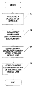
Now referring to Fig.5, there is shown how an estimated
position of a wireless mobile unit is computed according to
a first embodiment of the invention.
According to step 50, a plurality of beacons is provided.
The plurality of beacons is provided using the beacon data
manipulation unit 33. In one embodiment, the plurality of
beacons is provided by a user. Alternatively, the plurality
of beacons is automatically provided. Preferably, the user
provides the plurality of beacons through a user interface
displaying at least one part of the physical layout.
CA 02471921 2004-06-22
- 13 -
17020-1CAPR
According to step 52, the electromagnetic environment is
dynamically mapped. Now referring to Fig. 7, there is shown
how the electromagnetic environment is dynamically mapped.
According to step 70, a plurality of wireless bands is
detected using the wireless receiving unit 40.
According to step 72, an electromagnetic environment is
dynamically mapped for each of the plurality of wireless
bands. It should be understood that it is desirable to use
a plurality of wireless bands in order to enable an
accurate positioning. Using only a single frequency band
limits the accuracy of the positioning.
Now referring back to Fig. 3, the electromagnetic
environment is dynamically mapped using the electromagnetic
simulation unit 32 and the electromagnetic environment data
manipulation unit 35.
The resulting electromagnetic environment data is stored in
the electromagnetic environment data storing unit 36.
In an embodiment, the electromagnetic environment is
dynamically mapped in response to various events such as
detection of a new wireless transmitting unit, a dynamic
modification of the electromagnetic environment, etc.
It should be further understood that preferably a limited
part of the electromagnetic environment data storing unit
36 is updated each time.
According to step 54, a communication link is established
between the wireless mobile unit 10 and the wireless mobile
unit positioning server 18. Alternatively, the
communication link may be established between the wireless
CA 02471921 2004-06-22
- 14 -
17020-1CAPR
mobile unit 10 and a wireless transmitting unit of the
plurality of wireless transmitting units.
According to step 56, the estimated position of the
wireless mobile unit 10 is computed.
Referring to Fig. 8, there is shown how the estimated
position of the wireless mobile unit 10 is computed.
According to step 80, a signal indicative of a power signal
is provided. Alternatively, a signal indicative of a
signal/noise ratio is provided.
In the case where the wireless mobile unit 10 has a
communication established with one of the plurality of
wireless transmitting units, the signal indicative of a
power signal/SNR may be provided by one of the wireless
mobile unit ZO and the wireless transmitting unit. In the
case where the wireless mobile unit 10 has a communication
link established with the wireless mobile unit positioning
server 18, the signal indicative of a power signal/SNR may
be provided by one of the wireless mobile unit 10 and the
wireless mobile unit positioning server 18. It should be
understood that the signal indicative of a power signal/SNR
may or not be related to a frequency band used to
communicate with the wireless mobile unit 10: In the case
where the power signal/SNR is not related to the frequency
band used to communicate with the wireless mobile unit 10,
the power signal/SNR should be provided by the wireless
mobile unit 10.
According to step 82, the signal indicative of a power
signal/SNR is transmitted to the wireless mobile unit
positioning server 18. Alternatively, time information may
be used. In such case, the positioning server 18 provides
CA 02471921 2004-06-22
- 15 -
17020-1CAPR
the signal in a data packet having a high priority. By
measuring the amount of time required for transmitting and
retransmitting back the data packet to the wireless mobile
unit positioning server 18, and by estimating the time for
processing the data packet, it is possible to determine the
time information and therefore position the wireless mobile
unit l0.
The signal indicative of the power signal/SNR is received
by the wireless receiving unit 40 and transmitted to the
position processing unit 42.
According to step 84, the signal indicative of the power
signal/SNR is discriminated. It should be understood that
discrimination is performed in order to avoid providing a
distorted signal for instance or a prima facie
wrong/useless signal. The purpose of the discrimination is
to avoid merging a good value with a bad value. The
discrimination may be performed according to a plurality of
strategies.
A first discrimination strategy is to compare the value of
a given signal to discriminate with a more probable value.
The more probable value has been identified as reliable,
known. Such signal may be provided by a fixed beacon. The
first strategy would be to filter the given signal
according to the more probable value.
A second discrimination strategy is to compare the value of
a given signal to discriminate based on a frequency. As
explained previously a plurality of signals having various
frequencies may be collected in order to compute the
estimated position of the wireless mobile unit 10. A
measured wireless signal of a particular frequency may be
more reliable than another measured wireless signal of
CA 02471921 2004-06-22
- 16 -
17020-1CAPR
another frequency. Large variations in the value of a
signal of a given frequency band may be indicative of an
unreliable frequency band for estimating the position of
the wireless mobile unit 10.
A third discrimination strategy is to use a further
wireless receiver which discriminates the values of a given
signal and records negative variations and provides an
indication of whether a value of the given signal should be
or not taken.
A fourth discrimination strategy would be to have an
indication of a value to expect and to discriminate
according to this value.
A further discrimination strategy may be an empiric
strategy in which the wireless mobile unit 10 may recognize
that it must use a given wireless signal for a second time.
The empiric discrimination strategy is based upon providing
a value on the basis of a long observation period and
discriminating values directly upon receipt.
A further discrimination strategy may be based upon
simulating a value of a wireless signal depending upon
alterations that the signal should have encountered on its
propagation path. In such case, the surrounding environment
is used in order to simulate the value of the wireless
signal.
25. A further discrimination strategy may be based upon
applying filters on the signal.
A further discrimination strategy may be based upon a type
of material used.
CA 02471921 2004-06-22
- 17 -
17020-1CAPR
A further discrimination strategy may be based on the
environment surrounding the wireless mobile unit 10. The
skilled addressee will for instance appreciate that the
wireless mobile unit 10 may not go through walls for
instance. It will be also appreciated that a direct path
between a wireless transmitting unit 10 and the wireless
mobile unit positioning server 18 may be preferred.
According to step 86, a correction may be applied in order
to correct the discriminated signal. The correction may
l0 comprise at least one of merging at least two discriminated
signals, modifying at least one part of the discriminated
signal according to a statistical analysis or the like.
According to step 88, the corrected signal is processed in
order to provide an estimated position signal for the
wireless mobile unit 10.
The step of processing the corrected signal comprises
providing at least one part of the corrected signal to each
of the plurality of position estimation units, for each of
the position estimation units 44, 46, 48, accessing the
electromagnetic environment data storing unit 36,
processing received data using the corrected signal to
provide a corresponding estimated position signal and
providing an estimation signal by selecting one of the
corresponding estimated position signals provided by the
plurality of position estimation units.
In an embodiment, the processing of the corrected signal
may first comprise an analysis of at least one part of the
corrected signal. The analysis is based on the value of the
corrected signal either using by comparing the corrected
signal with a standard signal or by comparing the value of
the corrected signal with a former measured value.
CA 02471921 2004-06-22
- 18 -
17020-1CAPR
Now referring to Fig. 6, there is shown how an estimated
position of a wireless mobile unit 10 is computed according
to a second embodiment of the invention. In this
embodiment, the wireless mobile unit 10 is of the type
shown in Fig. 2b.
According to step 60, a plurality of beacons is provided.
The plurality of beacons is provided using the beacons data
manipulation unit 33. In one embodiment, the plurality of
beacons is provided by a user. Alternatively, the plurality
of beacons is automatically provided.
According to step 62, the electromagnetic environment is
dynamically mapped. Such mapping is performed similarly to
the mapping performed in step 52.
According to step 64, a communication link is established
with the wireless mobile unit 10.
According to step 66, inertial data is received from a
sensor. The inertial data may be received from the inertial
sensor unit 28.
According to step 68, a position of the wireless mobile
unit 10 is computed. In this embodiment, the received
inertial data is used in order to compute the estimated
position of the wireless mobile unit 10.
While it has been disclosed that the computing of the
estimated position signal is performed by the position
processing unit 42, it should be understood that at least
one part of the computing of the estimated position signal
may be alternatively performed by the wireless mobile unit
10. In such case, the optional memory unit 26 may comprise
a position estimation unit and at least one part of the
electromagnetic environment data storing unit 36. Still in
CA 02471921 2004-06-22
- 19 -
17020-1CAPR
the embodiment, the processing unit 24 of the wireless
mobile unit 10 may be used to compute the estimated
position signal.
It will further be appreciated that the estimated position
signal may be used in order to update the electromagnetic
environment data storing unit 36.
The embodiments of the invention described above are
intended to be exemplary only. The scope of the invention
is therefore intended to be limited solely by the scope of
the appended claims.