Note : Les descriptions sont présentées dans la langue officielle dans laquelle elles ont été soumises.
CA 02631416 2008-05-28
WO 2007/065434 PCT/DK2006/000689
1
Title: Blade for a wind turbine rotor
Technical Field
The present invention relates to a blade for a wind turbine rotor having a
substantially
horizontal rotor shaft, said rotor comprising a hub, where, seen in
longitudinal direction
along a longitudinal axis, the blade comprises a root area closest to the hub,
an airfoil
area furthest away from the hub and optionally a transition area between the
root area
and the airfoil area, and where, seen in transverse direction, said blade
comprises a
leading edge and a trailing edge as well as a chord plane extending between
the lead-
ing edge and the trailing edge of the blade.
Background Art
Ideally, a blade of the airfoil type is shaped like a typical aeroplane wing,
where the
chord plane width of the blade as well as the first derivative thereof
increase continu-
ously with decreasing distance to the hub. This results in the blade, ideally,
being com-
paratively wide in the vicinity of the hub. This again results in problems
when having to
mount the blade to the hub, and, moreover, this causes great loads when the
blade is
mounted, such as storm loads, due to the large surface area of the blade.
Therefore, over the years, the construction of blades has developed towards a
shape,
where the blade consists of a root area closest to the hub, an airfoil area
furthest away
from the hub and optionally a transition area between the root area and the
airfoil area.
The airfoil area has an ideal or almost ideal blade shape, whereas the root
area has a
substantially circular cross-section reducing the storm loads and making it
easier and
more safe to mount the blade to the hub. The root area diameter is preferably
constant
along the entire root area. Due to the circular cross-section, the root area
does not con-
tribute to the production of the wind turbine and, in fact, lowers the
production a little
because of wind resistance. As is suggested by the name, the transition area
has a
shape gradually changing from the circular shape of the root area to the
airfoil profile of
the airfoil area. Typically, the width of the transition area increases
substantially linearly
with increasing distance from the hub.
It is well known in golf that a golf ball with indentations (so-called
dimples) is able to fly
further than a golf ball with a smooth surface. This is due to the reduction
in aerody-
namic wind resistance the golf ball experiences when flying through the air.
The golf
ball is exposed to two types of wind resistance. The first type is due to
friction when the
CA 02631416 2008-05-28
WO 2007/065434 PCT/DK2006/000689
2
ball moves through the air, but friction alone accounts only for a small part
of the total
wind resistance the golf ball experiences. A major part of the wind resistance
arises
from a separation of the airflow behind the ball, which is referred to as
pressure loss
due to separation.
The larger the separation behind the golf ball, the larger the pressure loss
behind the
golf ball. Thus, the differential pressure between the front and the rear of
the ball in-
creases and therefore also the wind resistance the golf ball experiences.
In the case of laminar airflow past a sphere, the separation behind the golf
ball is com-
paratively large, while the separation is considerably smaller for a turbulent
airflow.
Therefore, golf balls have dimples, which causes the airflow around the golf
ball to
change from laminar to turbulent, which again makes the air flow "stick" to
the surface
of the golf ball for a longer period and reduces the separation behind the
golf ball.
Disclosure of Invention
The object of the invention is to provide a new and improved construction for
wind tur-
bine blades.
According to the invention, this object is achieved by a surface zone with a
plurality of
indentations and/or projections being provided in at least the root area, said
indenta-
tions and/or projections being formed and dimensioned to improve the wind flow
across
the surface of the blade, i.e. reducing the separation behind the trailing
edge of the
blade (or root area) during rotation of the rotor. The principles known from
the golf ball
with respect to creating a turbulent air flow are thus utilised. In this way,
the aerody-
namic air resistance of the root part is reduced, thus allowing for an
increase in wind
turbine production and a reduction of storm loads on the blade. This is
particularly ap-
plicable for especially large blades and blades with hub extenders.
Preferably, the sur-
face zone comprises a large number of indentations and/or projections.
Preferably, the blade is made as a shell body made of fibre-reinforced
polymer.
According to a preferred embodiment of the blade according to the invention,
the sur-
face zone extends substantially along the entire length of the root area.
Thus, the air
resistance is reduced along the entire length of the root area.
CA 02631416 2008-05-28
WO 2007/065434 PCT/DK2006/000689
3
According to a suitable embodiment, the root area has a substantially circular
cross-
section. In this way, it is easier to anchor the blade to the hub.
According to a particular embodiment, the surface zone comprises a first zone
segment
and a second zone segment, seen in angular direction, where the first and the
second
zone segment extend at least from 30 to 150 degrees and -30 to -150 degrees,
respec-
tively, or from 60 to 135 degrees and -60 to -135 degrees, respectively, or
from 60 to
120 degrees and -60 to -120 degrees, respectively, where the line from the
longitudinal
axis to the leading edge is defined as 0 degrees, and the line from the
longitudinal axis
to the trailing edge is defined as 180 degrees (or -180 degrees). However, the
indenta-
tions and/or projections may be arranged along the entire angular direction,
i.e.
from -180 degrees to -180 degrees
0 degrees with respect to the longitudinal axis may also be defined based on
the result-
ing wind direction experienced by the root area. Since the resulting wind
direction is a
cumulative vector of the actual wind velocity and the local velocity of the
blade, the op-
timum position of the first and the second zone segment is dependent on the
distance
from the hub. Thus, the positions of the two zone segments may be twisted in
longitu-
dinal direction in the same way the chord plane of a blade is often twisted in
the longi-
tudinal direction of the blade.
According to a particular embodiment of the invention, the surface zone
extends into
the transition area. In particular, the surface zone extends at least into the
area of the
transition area closest to the hub, and preferably extends along substantially
the entire
longitudinal direction of the transition area.
According to a preferred embodiment, the surface zone(s) extend only along
the inner 50%, or 35%, or 20%, or 10% of the blade radius.
According to a suitable embodiment, the first zone segment and the second zone
seg-
ment in the transition area are located around the point transverse to the
chord plane,
where the profile of the transition area has the greatest thickness.
CA 02631416 2008-05-28
WO 2007/065434 PCT/DK2006/000689
4
According to an alternative embodiment, at least one portion of the airfoil
area situated
closest to the hub and thus experiencing the lowest resulting wind velocity is
provided
with a plurality of indentations and/or projections.
According to an alternative embodiment, the plurality of indentations and/or
projections
is provided in the root area only.
According to a preferred embodiment of the blade according to the invention,
the sur-
face zone comprises a plurality of substantially uniform indentations or
projections.
According to a particularly preferred embodiment, the surface zone comprises a
plural-
ity of substantially circular, concave indentations. This corresponds to the
dimples on a
golf ball.
The surface zone may also comprise a plurality of hexagonal indentations,
which al-
lows a further reduction of air resistance. Of course, the surface zone may
also com-
prise a combination of indentations or projections having various shapes, such
as any
polygonial shape.
Furthermore, the indentations and/or projections may be of different sizes.
The sizes
may be selected dependent on the local velocity of the blade, which may mean
for ex-
ample that the individual areas and depths/heights of the indentations
increase with in-
creasing distance from the hub.
The indentations and/or projections may be arranged according to a
predetermined
pattern or, alternatively, the mutual positions of the indentations and/or
projections may
be random.
According to a particular embodiment, the indentations and/or projections have
a width
of 2-100 mm, 3-50 mm or 4-20 mm and a depth of 1-20 mm, 1-10 or 1-5 mm.
According to a preferred embodiment of the invention, the indentations are
recessed on
the surface of the blade. Thus, the surface structure may be established
during the
moulding process for the blade.
CA 02631416 2008-05-28
WO 2007/065434 PCT/DK2006/000689
Alternatively, the indentations and/or projections may be a part of a
covering, such as a
tape or a film, provided on the surface of the blade. This allows the
manufacture of
blades by means of existing moulds, and the surface of the blade is supplied
with said
covering first after the blade has been moulded.
5
According to the invention, the object is also achieved by a film or foil for
covering the
surface of a blade having a first face adapted to be fastened, e.g. by means
of gluing,
to the surface of the blade, and having a second face, which when said film is
fastened
to the blade, faces away from the surface of the blade, where the second face
of the
film is provided with a plurality of indentations and/or projections.
Brief Description of the Drawings
The invention is explained in greater detail below by way of embodiments which
are
shown in the drawings, in which
Fig. 1 shows a top view of an ideal blade of the airfoil type,
Fig. 2 shows a perspective view of a conventional blade of the airfoil type,
and
Fig. 3a and 3b show the airflow over a smooth sphere and a sphere having
indenta-
tions on the surface, respectively,
Fig. 4 shows a first embodiment of a blade according to the invention,
Fig. 5 shows a cross-section through the root area of a second embodiment of a
blade
according to the invention, and
Fig. 6 shows a cross-section through the transition area of a second
embodiment of a
blade according to the invention.
Best Modes for Carrying out the Invention
Fig. 1 shows an embodiment of an ideal blade 101 of the airfoil type. The
blade is pro-
vided with a root part 102 adapted to be secured to a hub of a wind turbine.
The ideal
blade 101 is designed such that the width of the blade 101 decreases with
increasing
distance L from the hub. Furthermore, the first derivative of the width of the
depicted
blade 101 also decreases with increasing distance from the hub 101, which
means
CA 02631416 2008-05-28
WO 2007/065434 PCT/DK2006/000689
6
that, ideally, the blade 101 is very wide at the root area 102. This causes
problems with
respect to securing the blade 101 to the hub. Moreover, when mounted, the
blade 101
impacts the hub with large storm loads because of the large surface area of
the
blade 101.
Therefore, over the years, the construction of blades has developed towards a
shape,
where the outer part of the blade corresponds to the ideal blade 101, whereas
the sur-
face area of the root area is substantially reduced compared to the ideal
blade. This
embodiment is illustrated with a dashed line in Fig. 1, a perspective view
thereof being
shown in Fig. 2.
As seen from Fig. 2, the conventional blade 201 comprises a root area 202
closest to
the hub, an airfoil area 204 furthest away from the hub and a transition area
203 be-
tween the root area 202 and the airfoil area 204. The blade 201 comprises a
leading
edge 205 facing the direction of rotation of the blade 201, when the blade is
mounted
on the hub, and a trailing edge 206 facing in the opposite direction to the
leading
edge 205. The airfoil area 204 has an ideal or almost ideal blade shape,
whereas the
root area 202 has a substantially circular cross-section, which reduces storm
loads and
makes it easier and more safe to mount the blade 201 to the hub. Preferably,
the di-
ameter of the root area 202 is constant along the entire root area 202. The
transition
area 203 has a shape gradually changing from the circular shape of the root
area 202
to the airfoil profile of the airfoil area 204. The width of the transition
area 203 increases
substantially linearly with increasing distance L from the hub.
The airfoil area 204 has an airfoil profile with a chord plane K extending
between the
leading edge 205 and the trailing edge 206 of the blade 201. The width of the
chord
plane decreases with increasing distance L from the hub. It should be noted
that the
chord plane does not necessarily run straight over its entire extent, since
the blade may
be twisted and/or curved, thus providing the chord plane with a
correspondingly twisted
and/or curved course, this being most often the case in order to compensate
for the lo-
cal velocity of the blade being dependent on the radius from the hub.
Due to the circular cross-section, the root area 202 does not contribute to
the produc-
tion of the wind turbine and, in fact, lowers the production a little because
of wind resis-
tance.
CA 02631416 2008-05-28
WO 2007/065434 PCT/DK2006/000689
7
Fig. 3a shows a laminar airflow 52 past a sphere 50, while Fig. 3b shows a
turbulent
airflow 62 past a sphere 60 with dimples. With laminar airflow 52, the
separation 51
behind the sphere 50 is comparatively large. Therefore, there is a great
pressure drop
behind the sphere, and thus the differential pressure between the front and
the rear of
the sphere 50 is correspondingly large. Said differential pressure causes a
force to act
on the rear of the sphere. With turbulent air flow 62, the separation 61
behind the
sphere 60 is considerably smaller, and thus the differential pressure between
the front
and the rear of the sphere 60 is considerably smaller, and therefore the force
acting
towards the rear of the sphere is also smaller.
The reason why e.g. golf balls have a surface with indentations or so-called
dimples is
based on the desire to alter the critical Reynolds number of the ball, which
is the Rey-
nolds number, where the flow changes from laminar to turbulent flow. For a
smooth
surface as shown in Fig. 3B, the critical Reynolds number is much higher than
the av-
erage Reynolds number which a golf ball achieves when moving through the air.
For a golf ball having a sandblasted surface the decrease in wind resistance
at the
critical Reynolds number is larger than for a golf ball with dimples. But the
wind resis-
tance increases with increasing Reynolds number. However, a golf ball with
dimples
has a low critical Reynolds number and the resistance is substantially
constant for
Reynolds numbers higher than the critical Reynolds number.
In other words, the indentations ensure a decrease of the critical Reynolds
number,
which results in the flow becoming turbulent at lower wind velocities than
with a smooth
sphere. This makes the air flow "stick" to the surface of the golf ball for a
longer period,
which results in a decrease in wind resistance.
The idea behind the surface is to use this known effect to reduce the wind
resistance
particularly in those parts of the wind turbine blade, where the blade does
not possess
an ideal airfoil profile, according to the principles known form golf balls.
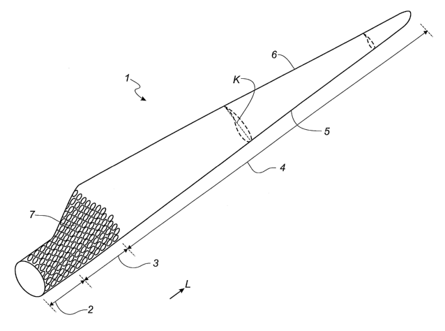
Fig. 4 shows a blade I according to the invention, where the root area 2 and
the transi-
tion area 3 are provided with a plurality of indentations and/or projections
7. Below,
these are referred to as-indentations or dimples, but it is apparent that they
may be
both concave and convex (i.e. projections). The airfoil area of the blade 1 is
not pro-
vided with indentations. The root area 2 is provided with indentations 7 along
its entire
CA 02631416 2008-05-28
WO 2007/065434 PCT/DK2006/000689
8
longitudinal direction, and said indentations 7 are preferably arranged all
the way
around the circular root area 2. The transition area 3 is depicted as having
indentations
along its entire longitudinal direction. It is most important, however, that
the area of the
transition area 3 situated closest to the root area 2 is provided with
indentations 7,
since this point of the cross-sectional profile shows the greatest deviation
from the ideal
airfoil profile. It should be noted that for the sake of clarity the
individual illustrated in-
dentations 7 are drawn out of scale and larger in the figure, and that in
reality they are
often considerably smaller.
Preferably, the entire root area 2 is provided with dimples 7 in the angular
direction. But
since the direction of rotation of the blade is well-defined with respect to
the wind direc-
tion (in contrast to golf balls), it may be sufficient to provide a first zone
segment 8 and
a second zone segment 9 with dimples. The zone segments 8, 9 may be arranged
as
shown in Fig. 5. The line from the longitudinal axis 10 of the blade 1 towards
the lead-
ing edge 5 of the blade is defined has having an angle of 0 degree, whereas
the line
from the longitudinal axis 10 of the blade 1 towards the trailing edge of the
blade is de-
fined has having an angle of 180 degrees. The first zone segment 8 extends in
the an-
gular direction from the angle a, to the angle a2, while the second zone
segment 9 ex-
tends from the angle -a, to -a2. Preferably, a, = 30 degrees and a2 = 150
degrees, but it
may be sufficient that a, = 60 degrees and a2 = 135 degrees and even
sufficient that a,
= 60 degrees and a2 = 120 degrees.
Preferably, the chord plane K of the blade extending between the leading edge
5 and
the trailing edge 6 of the blade 1 is oriented such that it follows the
resulting local wind
direction. Since this is dependent on the local velocity of the blade, the
chord plane is
preferably twisted in the longitudinal direction L of the blade 1. Thus, the
local position
of the two zone segments 8, 9 may also be twisted in the longitudinal
direction L of the
blade 1.
Fig. 6 shows a section through the transition area 3, where the traiiing edge
6 of the
profile may be more or less blunt or truncated. In the iliustrated embodiment,
the inden-
tations 7 are again arranged in two different zone segments 8, 9. Preferably,
said zone
segments are situated around the points transverse to the chord plane K where
the
thickness T of the profile is greatest. But as in the root area 2, the
indentations 7 are
preferably arranged all the way around the transition area 3 or at least from
the area,
CA 02631416 2008-05-28
WO 2007/065434 PCT/DK2006/000689
9
where the thickness T of the profile is greatest, all the way up to the
trailing edge 6 of
the blade 1.
For the sake of clarity, the indentations 7 illustrated in Fig. 5 and Fig. 6
are once again
drawn out of scale and are preferably considerably smaller with respect to the
size of
the profile.
The indentations 7 are preferably shaped like circular, concave indentations
corre-
sponding to dimples on a golf ball. However, they may be triangular,
rectangular, hex-
agonal or have any other polygonal shape. For example, a hexagonal shape
reduces
the wind resistance further compared to circular indentations. The
indentations may
also have varying shapes.
The indentations 7 may also have varying sizes. Preferably, the sizes are
selected on
the basis of the size of the blade I and the wind velocity the blade 1 is
exposed to.
Since the local speed of the blade I increases with increasing distance L from
the hub,
the resulting local wind velocity also increases with increasing distance from
the hub.
The size of the indentations 7 may thus be selected depending on the distance
L from
the hub. The mutual positions of the indentations 7 may be arranged after,a
predeter-
mined pattern or may be random.
The indentations 7 may be formed during manufacture of the blade 1, that is,
during the
moulding process itself. They can also be recessed after moulding the blade.
Alterna-
tively, the indentations 7 are formed by subsequently covering the surface of
the
blade I with a tape or film with indentations.
It may be advantageous to reduce the storm loads on the tower of the wind
turbine
while reducing the storm loads on the wind turbine blades. Often, the tower is
of sub-
stantially circular cross-section, and by providing in particular the
uppermost part of the
tower with a construction rotatably connected to the tower so that the cross-
section of
the tower together with said construction has the shape of a drag reduction
profile, i.e.
a substantially symmetrical drop shape, a considerable reduction in storm
loads may
be obtained, as shown by simulations. The construction must be rotatably
connected to
the tower in a way that it automatically orients itself with respect to the
wind direction
such that the "tip of the drop" points in the wind direction.
CA 02631416 2008-05-28
WO 2007/065434 PCT/DK2006/000689
The invention has been described with reference to preferred embodiments. Many
modifications are conceivable without thereby deviating from the scope of the
inven-
tion. Modifications and variations apparent to those skilled in the art are
considered to
fall within the scope of the present invention.
5
Reference numeral list
1, 101,201 blade
2, 102, 202 root area
10 3, 203 transition area
4, 204 airfoil area
5, 205 leading edge
6, 206 trailing edge
7 indentations/projections, dimples
8 first zone segment
9 second zone segment
10 longitudinal axis
50 smooth sphere
51 separation
52 air flow
60 sphere with dimples
61 separation
62 air flow
a, first angle
a2 second angle
L longitudinal direction
K chord plane
T thickness