Note : Les descriptions sont présentées dans la langue officielle dans laquelle elles ont été soumises.
CA 02759015 2013-10-08
STENTS HAVING CONTROLLED ELUTION
[0001]
[0002]
[0003]
15 BACKGROUND OF THE INVENTION
[0004] Drug-eluting stents are used to address the drawbacks of bare stents,
namely to treat
restenosis and to promote healing of the vessel after opening the blockage by
PCl/stenting. Some current drug eluting stents can have physical, chemical and
therapeutic legacy in the vessel over time. Others may have less legacy, bur
are not
optimized for thickenss, deployment flexibility, access to difficult lesions,
and
minimization of vessel wall intrusion.
SUMMARY OF THE INVENTION
[0005] The present invention relates to methods for forming stents comprising
a
bioabsorbable polymer and a pharmaceutical or biological agent in powder form
onto
a substrate.
[0006] It is desirable to have a drug-eluting stent with minimal physical,
chemical and
therapeutic legacy in the vessel after a proscribed period of time. This
period of time
1
CA 02759015 2011-10-17
WO 2010/121187 PCT/US2010/031470
is based on the effective healing of the vessel after opening the blockage by
PCl/stenting (currently believed by leading clinicians to be 6-18 months).
[0007] It is also desirable to have drug-eluting stents of minimal cross-
sectional thickness for
(a) flexibility of deployment (b) access to small vessels (c) minimized
intrusion into
the vessel wall and blood.
[0008] Provided herein is a device comprising a stent; and a coating on the
stent; wherein the
coating comprises at least one bioabsorbable polymer and at least one active
agent;
wherein the active agent is present in crystalline form on at least one region
of an
outer surface of the coating opposite the stent and wherein 50% or less of the
total
1 o amount of active agent in the coating is released after 24 hours in
vitro elution.
[0009] In some embodiments, in vitro elution is carried out in a 1:1
spectroscopic grade
ethanol/phosphate buffer saline at pH 7.4 and 37 C; wherein the amount of
active
agent released is determined by measuring UV absorption. In some embodiments,
UV
absorption is detected at 278 nm by a diode array spectrometer.
[0010] In some embodiments, presence of active agent on at least a region of
the surface of
the coating is determined by cluster secondary ion mass spectrometry (cluster
SIMS).
In some embodiments, presence of active agent on at least a region of the
surface of
the coating is determined by generating cluster secondary ion mass
spectrometry
(cluster SIMS) depth profiles. In some embodiments, presence of active agent
on at
least a region of the surface of the coating is determined by time of flight
secondary
ion mass spectrometry (TOF-SIMS). In some embodiments, presence of active
agent
on at least a region of the surface of the coating is determined by atomic
force
microscopy (AFM). In some embodiments, presence of active agent on at least a
region of the surface of the coating is determined by X-ray spectroscopy. In
some
embodiments, presence of active agent on at least a region of the surface of
the coating
is determined by electronic microscopy. In some embodiments, presence of
active
agent on at least a region of the surface of the coating is determined by
Raman
spectroscopy.
[0011] In some embodiments, between 25% and 45% of the total amount of active
agent in
the coating is released after 24 hours in vitro elution in a 1:1 spectroscopic
grade
ethanol/phosphate buffer saline at pH 7.4 and 37 C; wherein the amount of the
active
agent released is determined by measuring UV absorption at 278 nm by a diode
array
spectrometer.
2
CA 02759015 2011-10-17
WO 2010/121187 PCT/US2010/031470
[0012] In some embodiments, the active agent is at least 50% crystalline. In
some
embodiments, the active agent is at least 75% crystalline. In some
embodiments, the
active agent is at least 90% crystalline.
[0013] In some embodiments, the polymer comprises a PLGA copolymer. In some
embodiments, the coating comprises a first PLGA copolymer with a ratio of
about
40:60 to about 60:40 and a second PLGA copolymer with a ratio of about 60:40
to
about 90:10. In some embodiments, the coating comprises a first PLGA copolymer
having a molecular weight of about 10kD and a second polymer is a PLGA
copolymer
having a molecular weight of about 19kD.
[0014] In some embodiments, the bioabsorbable polymer is selected from the
group PLGA,
PGA poly(glycolide), LPLA poly(1-lactide), DLPLA poly(dl-lactide), PCL poly(e-
caprolactone) PDO, poly(dioxolane) PGA-TMC, 85/15 DLPLG p(dl-lactide-co-
glycolide), 75/25 DLPL, 65/35 DLPLG, 50/50 DLPLG, TMC
poly(trimethylcarbonate),
p(CPP:SA) poly(1,3-bis-p-(carboxyphenoxy)propane-co-sebacic acid).
[0015] In some embodiments, the stent is formed of stainless steel material.
In some
embodiments, the stent is formed of a material comprising a cobalt chromium
alloy. In
some embodiments, the stent is formed from a material comprising the following
percentages by weight: about 0.05 to about0.15 C, about 1.00 to about2.00 Mn,
about
0.04 Si, about 0.03 P, about 0.3 S, about 19.0 to about21.0 Cr, about 9.0 to
about11.0
Ni, about 14.0 to about 16.00 W, about 3.0 Fe, and Bal. Co. In some
embodiments, the
stent is formed from a material comprising at most the following percentages
by
weight: about 0.025 C, about 0.15 Mn, aboout 0.15 Si, about 0.015 P, about
0.01 S,
about 19.0 to about21.0 Cr, about 33 to about37 Ni, about 9.0 to about 10.5
Mo, about
1.0 Fe, about 1.0 Ti, and Bal. Co. In some embodiments, the stent is formed
from a
material comprising L605 alloy.
[0016] In some embodiments, the stent has a thickness of from about 50% to
about 90% of a
total thickness of the device. In some embodiments, the device has a thickness
of from
about 20 i_tm to about 500 lam. In some embodiments, the stent has a thickness
of from
about 50 i_tm to about 80 lam. In some embodiments, the coating has a total
thickness
of from about 5 i_tm to about 50 lam. In some embodiments, the device has an
active
agent content of from about 5 [tg to about 500 [tg. In some embodiments, the
device
has an active agent content of from about 100 [tg to about 160 [tg.
3
CA 02759015 2011-10-17
WO 2010/121187 PCT/US2010/031470
[0017] In some embodiments, the active agent is selected from rapamycin, a
prodrug, a
derivative, an analog, a hydrate, an ester, and a salt thereof In some
embodiments, the
active agent is selected from one or more of sirolimus, everolimus,
zotarolimus and
biolimus. In some embodiments, the active agent comprises a macrolide
immunosuppressive (limus) drug. In some embodiments, the macrolide
immunosuppressive drug comprises one or more of rapamycin, biolimus (biolimus
A9), 40-0-(2-Hydroxyethyl)rapamycin (everolimus), 40-0-Benzyl-rapamycin, 40-0-
(4'-Hydroxymethyl)benzyl-rapamycin, 40-044'-(1,2-Dihydroxyethyl)]benzyl-
rapamycin, 40-0-Allyl-rapamycin, 40-0-[3'-(2,2-Dimethy1-1,3-dioxolan-4(S)-y1)-
prop-2'-en-1'-y1]-rapamycin, (2':E,4'S)-40-0-(4',5'-Dihydroxypent-2'-en-1'-y1)-
rapamycin 40-0-(2-Hydroxy)ethoxycar-bonylmethyl-rapamycin, 40-0-(3-
Hydroxy)propyl-rapamycin 40-0-(6-Hydroxy)hexyl-rapamycin 40-04242-
Hydroxy)ethoxy]ethyl-rapamycin 40-0-[(3S)-2,2-Dimethyldioxolan-3-yl]methyl-
rapamycin, 40-0-[(2S)-2,3-Dihydroxyprop-1-y1]-rapamycin, 40-0-(2-Acetoxy)ethyl-
rapamycin 40-0-(2-Nicotinoyloxy)ethyl-rapamycin, 40-042-(N-
Morpholino)acetoxy]ethyl-rapamycin 40-0-(2-N-Imidazolylacetoxy)ethyl-
rapamycin,
40-042-(N-Methyl-N'-piperazinyl)acetoxy]ethyl-rapamycin, 39-0-Desmethy1-39,40-
0,0-ethylene-rapamycin, (26R)-26-Dihydro-40-0-(2-hydroxy)ethyl-rapamycin, 28-0-
Methyl-rapamycin, 40-0-(2-Aminoethyl)-rapamycin, 40-0-(2-Acetaminoethyl)-
rapamycin 40-0-(2-Nicotinamidoethyl)-rapamycin, 40-0-(2-(N-Methyl-imidazo-2'-
ylcarbethoxamido)ethyl)-rapamycin, 40-0-(2-Ethoxycarbonylaminoethyl)-
rapamycin,
40-0-(2-Tolylsulfonamidoethyl)-rapamycin, 40-0-[2-(4',5'-Dicarboethoxy-
1',2',3'-
triazol-1'-y1)-ethyl]-rapamycin, 42-Epi-(tetrazolyl)rapamycin (tacrolimus), 42-
[3-
hydroxy-2-(hydroxymethyl)-2-methylpropanoate]rapamycin (temsirolimus), (42S)-
42-
Deoxy-42-(1H-tetrazol-1-y1)-rapamycin (zotarolimus), and salts, derivatives,
isomers,
racemates, diastereoisomers, prodrugs, hydrate, ester, or analogs thereof
[0018] Provided herein is a device comprising a stent; anda coating on the
stent; wherein the
coating comprises at least one polymer and at least one active agent; wherein
the
active agent is present in crystalline form on at least one region of an outer
surface of
the coating opposite the stent and wherein between 25% and 50% of the total
amount
of active agent in the coating is released after 24 hours in vitro elution.
[0019] In some embodiments, the polymer comprises is at least one of: a
fluoropolymer,
PVDF-HFP comprising vinylidene fluoride and hexafluoropropylene monomers, PC
4
CA 02759015 2011-10-17
WO 2010/121187 PCT/US2010/031470
(phosphorylcholine), Polysulfone, polystyrene-b-isobutylene-b-styrene, PVP
(polyvinylpyrrolidone), alkyl methacrylate, vinyl acetate, hydroxyalkyl
methacrylate,
and alkyl acrylate. In some embodiments, the alkyl methacrylate comprises at
least
one of methyl methacrylate, ethyl methacrylate, propyl methacrylate, butyl
methacrylate, hexyl methacrylate, octyl methacrylate, dodecyl methacrylate,
and
lauryl methacrylate. In some embodiments, the alkyl acrylate comprises at
least one
of methyl acrylate, ethyl acrylate, propyl acrylate, butyl acrylate, hexyl
acrylate, octyl
acrylate, dodecyl acrylates, and lauryl acrylate.
[0020] In some embodiments, the polymer is not a polymer selected from: PBMA
(poly n-
butyl methacrylate), Parylene C, and polyethylene-co-vinyl acetate.
[0021] In some embodiments, the polymer comprises a durable polymer. In some
embodiments, the polymer comprises a bioabsorbable polymer. In some
embodiments,
the bioabsorbable polymer is selected from the group PLGA, PGA
poly(glycolide),
LPLA poly(1-lactide), DLPLA poly(dl-lactide), PCL poly(e-caprolactone) PDO,
poly(dioxolane) PGA-TMC, 85/15 DLPLG p(dl-lactide-co-glycolide), 75/25 DLPL,
65/35 DLPLG, 50/50 DLPLG, TMC poly(trimethylcarbonate), p(CPP:SA) poly(1,3-
bis-p-(carboxyphenoxy)propane-co-sebacic acid).
[0022] In some embodiments, in vitro elution is carried out in a 1:1
spectroscopic grade
ethanol/phosphate buffer saline at pH 7.4 and 37 C; wherein the amount of
active
agent released is determined by measuring UV absorption.
[0023] In some embodiments, the active agent is at least 50% crystalline. In
some
embodiments, the active agent is at least 75% crystalline. In some
embodiments, the
active agent is at least 90% crystalline.
[0024] In some embodiments, the stent is formed of at least one of stainless
steel material and
a cobalt chromium alloy.
[0025] In some embodiments, the stent has a thickness of from about 50% to
about 90% of a
total thickness of the device. In some embodiments, the device has a thickness
of from
about 20 i_tm to about 500 lam. In some embodiments, the stent has a thickness
of from
about 50 i_tm to about 80 lam. In some embodiments, the coating has a total
thickness
of from about 5 [tm to about 50 lam. In some embodiments, the device has a
pharmaceutical agent content of from about 5 [tg to about 500[Lg. In some
embodiments, the device has a pharmaceutical agent content of from about 100
[tg to
about 160[Lg.
5
CA 02759015 2013-10-08
10026) In some embodiments, the active agent is selected from rapatnyein, a
prodrug, a
derivative, an analog, a hydrate, an ester, and a salt thereof. In some
embodiments, the
active agent comprises a macrolide immunosuppressive (limus) drug. In some
embodiments, the macrolide immunosuppressive drug comprises one or more of
rapamycin, biolimus (biolimus A9), 40-0-(2-HydroxyethyDrapamycin (everolimus),
40-0-Benzyl-rapamycin, 40-0-(4'-Hydroxymethyl)benzyl-rapamycin,
DihydroxyethylAbenzyl-rapamyein, 40-0-Allyl-rapamycin, 40-0-13'-(2,2-Dimethyl-
1,3-dioxolan-4(S)-y1)-prop-2'-en-1 '-yll-raparnycin, (2T:E,41S)-40-0-(4',5'-
Dihydroxypent-2'-en-1'-y1)-rapamyein 40-0-(2-Hydroxy)ethoxycar-bonylmethyl-
0 rapamycin, 40-0-(3-Hydroxy)propyl-rapamycin 40-0-(6-Hydroxy)hexyl-
rapamycin
40-012-(2-Hydroxy)ethoxy]ethyl-rapamycin 40-0-[(3S)-2,2-Dimethyldioxolan-3-
ylimethyl-raparnycin, 40-0-[(2S)-2,3-Dihydroxyprop-1-y1}-rapamycin, 40-042-
Acetoxy)ethyl-rapamycin 40-0-(2-Nicotinoyloxy)ethyl-rapamycin, 40-042-(N-
Morpholino)acetoxy]ethyl-raparnycin 40-0-(2-N-Imidazolylacetoxy)ethyl-
rapamycin,
40-042-(N-Methyl-N'-piperazinyl)acetoxy]ethyl-rapamyein, 39-0-Desmethy1-39,40-
0,0-ethylene-rapamycin, (261)-26-Dihydro-40-0-(2-hydroxy)ethyl-rapamycin, 28-0-
Methyl-rapamycin, 40-0-(2-Aminoethyl)-rapamycin, 40-0-(2-Acetaminoethyl)-
raparnycin 40-0-(2-Nicolinamidoethyl)-rapamycin, 40-0-(2-(N-Methyl-imidazo-2'-
ylearbethoxamido)ethyl)-rapamycin, 40-0-(2-Ethoxycarbonylaminoethyl)-
rapamycin,
40-0-(2-Tolylsulfonamidoethyp-rapamycin,
triazol-1'-y1)-ethyl}-rapamycin, 42-Epi-(tetrazolyl)rapamycin (tacrolimus),
4243-
hydroxy-2-(hydroxymethyI)-2-methylpropanoatelrapamycin (temsirolimus), (42S)-
42-
Deoxy-42-(1H-tetrazol-1-y1)-rapamycin (zotarolimus), and salts, derivatives,
isomers,
racemates, diastereoisomers, prodrugs, hydrate, ester, or analogs thereof'.
[0027]
3o
BRIEF DESCRIPTION OF THE DRAWINGS
6
CA 02759015 2011-10-17
WO 2010/121187 PCT/US2010/031470
[0028] The novel features of the invention are set forth with particularity in
the appended
claims. A better understanding of the features and advantages of the present
invention
will be obtained by reference to the following detailed description that sets
forth
illustrative embodiments, in which the principles of the invention are
utilized, and the
accompanying drawings of which:
[0029] Figure 1 depicts Bioabsorbability testing of 50:50 PLGA-ester end group
(MW ¨
19kD) polymer coating formulations on stents by determination of pH Changes
with
Polymer Film Degradation in 20% Ethanol/Phosphate Buffered Saline as set forth
in
Example 3 described herein.
[0030] Figure 2 depicts Bioabsorbability testing of 50:50 PLGA-carboxylate end
group (MW
¨ 10kD) PLGA polymer coating formulations on stents by determination of pH
Changes with Polymer Film Degradation in 20% Ethanol/Phosphate Buffered Saline
as set forth in Example 3 described herein.
[0031] Figure 3 depicts Bioabsorbability testing of 85:15 (85% lactic acid,
15% glycolic acid)
PLGA polymer coating formulations on stents by determination of pH Changes
with
Polymer Film Degradation in 20% Ethanol/Phosphate Buffered Saline as set forth
in
Example 3 described herein.
[0032] Figure 4 depicts Bioabsorbability testing of various PLGA polymer
coating film
formulations by determination of pH Changes with Polymer Film Degradation in
20%
Ethanol/Phosphate Buffered Saline as set forth in Example 3 described herein.
[0033] Figure 5 depicts Rapamycin Elution Profile of coated stents
(PLGA/Rapamycin
coatings) where the elution profile was determined by a static elution media
of 5%
Et0H/water, pH 7.4, 37 C via UV-Vis test method as described in Example 1 lb
of
coated stents described therein.
[0034] Figure 6 depicts Rapamycin Elution Profile of coated stents
(PLGA/Rapamycin
coatings) where the elution profile was determined by static elution media of
5%
Et0H/water, pH 7.4, 37 C via a UV-Vis test method as described in Example 1 lb
of
coated stents described therein.
[0035] Figure 7 depicts Rapamycin Elution Rates of coated stents
(PLGA/Rapamycin
coatings) where the static elution profile was compared with agitated elution
profile by
an elution media of 5% Et0H/water, pH 7.4, 37 C via a UV-Vis test method a UV-
Vis
test method as described in Example 1 lb of coated stents described therein.
7
CA 02759015 2011-10-17
WO 2010/121187 PCT/US2010/031470
[0036] Figure 8 depicts Rapamycin Elution Profile of coated stents
(PLGA/Rapamycin
coatings) where the elution profile by 5% Et0H/water, pH 7.4, 37 C elution
buffer
was compare with the elution profile using phosphate buffer saline pH 7.4, 37
C; both
profiles were determined by a UV-Vis test method as described in Example 1 lb
of
coated stents described therein.
[0037] Figure 9 depicts Rapamycin Elution Profile of coated stents
(PLGA/Rapamycin
coatings) where the elution profile was determined by a 20% Et0H/phosphate
buffered saline, pH 7.4, 37 C elution buffer and a HPLC test method as
described in
Example 11c described therein, wherein the elution time (x-axis) is expressed
linearly.
[0038] Figure 10 depicts Rapamycin Elution Profile of coated stents
(PLGA/Rapamycin
coatings) where the elution profile was determined by a 20% Et0H/phosphate
buffered saline, pH 7.4, 37 C elution buffer and a HPLC test method as
described in
Example 11c of described thereinõ wherein the elution time (x-axis) is
expressed in
logarithmic scale (i.e., log(time)).
[0039] Figure 11 depicts Vessel wall tissue showing various elements near the
lumen.
[0040] Figure 12 depicts Low-magnification cross-sections of porcine coronary
artery stent
implants (AS1, AS2 and Bare-metal stent control) at 28 days post-implantation
as
described in Example 25.
[0041] Figure 13 depicts Low-magnification cross-sections of porcine coronary
artery stent
implants (AS1, A52 and Bare-metal stent control) at 90 days post-implantation
as
described in Example 25.
[0042] Figure 14 depicts Low-magnification cross-sections of porcine coronary
artery stent
implants depicting AS1 and A52 drug depots as described in Example 25.
[0043] Figure 15 depicts Low-magnification cross-sections of porcine coronary
artery AS1
stent implants at 90 days depicting drug depots as described in Example 25.
[0044] Figure 16 depicts Mean (n=3) Sirolimus Levels in Arterial Tissue
Following AS1 and
Cypher Stent Implantations in Swine Coronary Arteries expressed as absolute
tissue
level (y-axis) versus time (x-axis) following testing as described in Example
25.
[0045] Figure 17 depicts Mean (n=3) Sirolimus Levels in Arterial Tissue
Following Various
Stent Implantations in Swine Coronary Arteries expressed as absolute tissue
level (y-
axis) versus time (x-axis) following testing as described in Example 25.
[0046] Figure 18 depicts Arterial Tissue Concentrations (y-axis) versus time
(x-axis) for AS1
and A52 stents following testing as described in Example 25.
8
CA 02759015 2011-10-17
WO 2010/121187 PCT/US2010/031470
[0047] Figure 19 depicts Mean (n=3) Sirolimus Levels in Arterial Tissue
Following Various
Stent Implantations in Swine Coronary Arteries expressed as stent level (y-
axis)
versus time (x-axis) following testing as described in Example 25.
[0048] Figure 20 depicts Mean (n=3) Sirolimus Levels remaining on stents in
Following AS1
and Cypher Stent Implantations in Swine Coronary Arteries expressed as stent
level
(y-axis) versus time (x-axis) following testing as described in Example 25.
[0049] Figure 21 depicts Fractional Sirolimus Release (y-axis) versus time (x-
axis) in Arterial
Tissue for AS1 and A52 Stents following testing as described in Example 25.
[0050] Figure 22 depicts: Sirolimus Blood Concentration following Single Stent
Implant
io expressed in Blood Concentration (ng/mL) (y-axis) versus time (x-axis)
following
testing as described in Example 25.
[0051] Figure 23 depicts: Mean (Single stent normalized) Blood Concentration
Immediately
post implant (between 15 minutes and 1 hour, typically 30 minutes) expressed
as
Blood Concentrations (ng/mL) (y-axis) for a Cypher stent, and stents having
coatings
as described herein (AS21, AS1, AS23, A524 are devices comprising coatings as
described herein) following testing as described in Example 25.
[0052] Figure 24 depicts an elution profile of stents coated according to
methods described in
Example 26, and having coatings described therein where the test group (upper
line at
day 2) has an additional sintering step performed between the 2d and third
polymer
application to the stent in the 3d polymer layer.
[0053] Figure 25 depicts an elution profile of stents coated according to
methods described in
Example 27, and having coatings described therein where the test group (bottom
line)
has an additional 15 second spray after final sinter step of normal process
(control)
followed by a sinter step.
[0054] Figure 26 depicts an elution profile of stents coated according to
methods described in
Example 28, and having coatings described therein where the test group (bottom
line)
has less polymer in all powder coats of final layer (1 second less for each of
3 sprays),
then sintering, and then an additional polymer spray (3 seconds) and
sintering.
[0055] Figure 27 depicts an elution profile of stents coated according to
methods described in
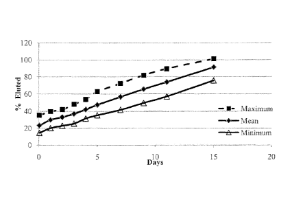
Example 30, and having coatings described therein wherein the figure shows the
average (or mean) percent elution of all the tested stents at each time point
(middle
line), expressed as % rapamycin total mass eluted (y-axis) at each time point
(x-axis).
DETAILED DESCRIPTION
9
CA 02759015 2011-10-17
WO 2010/121187 PCT/US2010/031470
[0056] The present invention is explained in greater detail below. This
description is not
intended to be a detailed catalog of all the different ways in which the
invention may
be implemented, or all the features that may be added to the instant
invention. For
example, features illustrated with respect to one embodiment may be
incorporated into
other embodiments, and features illustrated with respect to a particular
embodiment
may be deleted from that embodiment. In addition, numerous variations and
additions
to the various embodiments contemplated herein will be apparent to those
skilled in
the art in light of the instant disclosure, which do not depart from the
instant invention.
Hence, the following specification is intended to illustrate selected
embodiments of
the invention, and not to exhaustively specify all permutations, combinations
and
variations thereof
Definitions
[0057] As used in the present specification, the following words and phrases
are generally
intended to have the meanings as set forth below, except to the extent that
the context
in which they are used indicates otherwise.
[0058] "Substrate" as used herein, refers to any surface upon which it is
desirable to deposit a
coating comprising a polymer and a pharmaceutical or biological agent, wherein
the
coating process does not substantially modify the morphology of the
pharmaceutical
agent or the activity of the biological agent. Biomedical implants are of
particular
interest for the present invention; however the present invention is not
intended to be
restricted to this class of substrates. Those of skill in the art will
appreciate alternate
substrates that could benefit from the coating process described herein, such
as
pharmaceutical tablet cores, as part of an assay apparatus or as components in
a
diagnostic kit (e.g. a test strip).
[0059] "Biomedical implant" as used herein refers to any implant for insertion
into the body
of a human or animal subject, including but not limited to stents (e.g.,
coronary stents,
vascular stents including peripheral stents and graft stents, urinary tract
stents,
urethral/prostatic stents, rectal stent, oesophageal stent, biliary stent,
pancreatic stent),
electrodes, catheters, leads, implantable pacemaker, cardioverter or
defibrillator
housings, joints, screws, rods, ophthalmic implants, femoral pins, bone
plates, grafts,
anastomotic devices, perivascular wraps, sutures, staples, shunts for
hydrocephalus,
dialysis grafts, colostomy bag attachment devices, ear drainage tubes, leads
for pace
CA 02759015 2011-10-17
WO 2010/121187 PCT/US2010/031470
makers and implantable cardioverters and defibrillators, vertebral disks, bone
pins,
suture anchors, hemostatic barriers, clamps, screws, plates, clips, vascular
implants,
tissue adhesives and sealants, tissue scaffolds, various types of dressings
(e.g., wound
dressings), bone substitutes, intraluminal devices, vascular supports, etc.
[0060] The implants may be formed from any suitable material, including but
not limited to
polymers (including stable or inert polymers, organic polymers, organic-
inorganic
copolymers, inorganic polymers, and biodegradable polymers), metals, metal
alloys,
inorganic materials such as silicon, and composites thereof, including layered
structures with a core of one material and one or more coatings of a different
material.
io Substrates made of a conducting material facilitate electrostatic
capture. However, the
invention contemplates the use of electrostatic capture, as described below,
in
conjunction with substrate having low conductivity or which are non-
conductive. To
enhance electrostatic capture when a non-conductive substrate is employed, the
substrate is processed for example while maintaining a strong electrical field
in the
vicinity of the substrate.
[0061] Subjects into which biomedical implants of the invention may be applied
or inserted
include both human subjects (including male and female subjects and infant,
juvenile,
adolescent, adult and geriatric subjects) as well as animal subjects
(including but not
limited to pig, rabbit, mouse, dog, cat, horse, monkey, etc.) for veterinary
purposes
and/or medical research.
[0062] In a preferred embodiment the biomedical implant is an expandable
intraluminal
vascular graft or stent (e.g., comprising a wire mesh tube) that can be
expanded within
a blood vessel by an angioplasty balloon associated with a catheter to dilate
and
expand the lumen of a blood vessel, such as described in US Patent No.
4,733,665 to
Palmaz.
[0063] "Pharmaceutical agent" as used herein refers to any of a variety of
drugs or
pharmaceutical compounds that can be used as active agents to prevent or treat
a
disease (meaning any treatment of a disease in a mammal, including preventing
the
disease, i.e. causing the clinical symptoms of the disease not to develop;
inhibiting the
disease, i.e. arresting the development of clinical symptoms; and/or relieving
the
disease, i.e. causing the regression of clinical symptoms). It is possible
that the
pharmaceutical agents of the invention may also comprise two or more drugs or
pharmaceutical compounds. Pharmaceutical agents, include but are not limited
to
11
CA 02759015 2011-10-17
WO 2010/121187 PCT/US2010/031470
antirestenotic agents, antidiabetics, analgesics, antiinflammatory agents,
antirheumatics, antihypotensive agents, antihypertensive agents, psychoactive
drugs,
tranquillizers, antiemetics, muscle relaxants, glucocorticoids, agents for
treating
ulcerative colitis or Crohn's disease, antiallergics, antibiotics,
antiepileptics,
anticoagulants, antimycotics, antitussives, arteriosclerosis remedies,
diuretics,
proteins, peptides, enzymes, enzyme inhibitors, gout remedies, hormones and
inhibitors thereof, cardiac glycosides, immunotherapeutic agents and
cytokines,
laxatives, lipid-lowering agents, migraine remedies, mineral products,
otologicals, anti
parkinson agents, thyroid therapeutic agents, spasmolytics, platelet
aggregation
io inhibitors, vitamins, cytostatics and metastasis inhibitors,
phytopharmaceuticals,
chemotherapeutic agents and amino acids. Examples of suitable active
ingredients are
acarbose, antigens, beta-receptor blockers, non-steroidal antiinflammatory
drugs
[NSAIDs], cardiac glycosides, acetylsalicylic acid, virustatics, aclarubicin,
acyclovir,
cisplatin, actinomycin, alpha- and beta-sympatomimetics, (dmeprazole,
allopurinol,
alprostadil, prostaglandins, amantadine, ambroxol, amlodipine, methotrexate, S-
aminosalicylic acid, amitriptyline, amoxicillin, anastrozole, atenolol,
azathioprine,
balsalazide, beclomethasone, betahistine, bezafibrate, bicalutamide, diazepam
and
diazepam derivatives, budesonide, bufexamac, buprenorphine, methadone, calcium
salts, potassium salts, magnesium salts, candesartan, carbamazepine,
captopril,
cefalosporins, cetirizine, chenodeoxycholic acid, ursodeoxycholic acid,
theophylline
and theophylline derivatives, trypsins, cimetidine, clarithromycin, clavulanic
acid,
clindamycin, clobutinol, clonidine, cotrimoxazole, codeine, caffeine, vitamin
D and
derivatives of vitamin D, colestyramine, cromoglicic acid, coumarin and
coumarin
derivatives, cysteine, cytarabine, cyclophosphamide, ciclosporin, cyproterone,
cytabarine, dapiprazole, desogestrel, desonide, dihydralazine, diltiazem,
ergot
alkaloids, dimenhydrinate, dimethyl sulphoxide, dimeticone, domperidone and
domperidan derivatives, dopamine, doxazosin, doxorubizin, doxylamine,
dapiprazole,
benzodiazepines, diclofenac, glycoside antibiotics, desipramine, econazole,
ACE
inhibitors, enalapril, ephedrine, epinephrine, epoetin and epoetin
derivatives,
morphinans, calcium antagonists, irinotecan, modafinil, orlistat, peptide
antibiotics,
phenytoin, riluzoles, risedronate, sildenafil, topiramate, macrolide
antibiotics,
oestrogen and oestrogen derivatives, progestogen and progestogen derivatives,
testosterone and testosterone derivatives, androgen and androgen derivatives,
12
CA 02759015 2011-10-17
WO 2010/121187 PCT/US2010/031470
ethenzamide, etofenamate, etofibrate, fenofibrate, etofylline, etoposide,
famciclovir,
famotidine, felodipine, fenofibrate, fentanyl, fenticonazole, gyrase
inhibitors,
fluconazole, fludarabine, fluarizine, fluorouracil, fluoxetine, flurbiprofen,
ibuprofen,
flutamide, fluvastatin, follitropin, formoterol, fosfomicin, furosemide,
fusidic acid,
gallopamil, ganciclovir, gemfibrozil, gentamicin, ginkgo, Saint John's wort,
glibenclamide, urea derivatives as oral antidiabetics, glucagon, glucosamine
and
glucosamine derivatives, glutathione, glycerol and glycerol derivatives,
hypothalamus
hormones, goserelin, gyrase inhibitors, guanethidine, halofantrine,
haloperidol,
heparin and heparin derivatives, hyaluronic acid, hydralazine,
hydrochlorothiazide and
1 o hydrochlorothiazide derivatives, salicylates, hydroxyzine, idarubicin,
ifosfamide,
imipramine, indometacin, indoramine, insulin, interferons, iodine and iodine
derivatives, isoconazole, isoprenaline, glucitol and glucitol derivatives,
itraconazole,
ketoconazole, ketoprofen, ketotifen, lacidipine, lansoprazole, levodopa,
levomethadone, thyroid hormones, lipoic acid and lipoic acid derivatives,
lisinopril,
lisuride, lofepramine, lomustine, loperamide, loratadine, maprotiline,
mebendazole,
mebeverine, meclozine, mefenamic acid, mefloquine, meloxicam, mepindolol,
meprobamate, meropenem, mesalazine, mesuximide, metamizole, metformin,
methotrexate, methylphenidate, methylprednisolone, metixene, metoclopramide,
metoprolol, metronidazole, mianserin, miconazole, minocycline, minoxidil,
misoprostol, mitomycin, mizolastine, moexipril, morphine and morphine
derivatives,
evening primrose, nalbuphine, naloxone, tilidine, naproxen, narcotine,
natamycin,
neostigmine, nicergoline, nicethamide, nifedipine, niflumic acid, nimodipine,
nimorazole, nimustine, nisoldipine, adrenaline and adrenaline derivatives,
norfloxacin,
novamine sulfone, noscapine, nystatin, ofloxacin, olanzapine, olsalazine,
omeprazole,
omoconazole, ondansetron, oxaceprol, oxacillin, oxiconazole, oxymetazoline,
pantoprazole, paracetamol, paroxetine, penciclovir, oral penicillins,
pentazocine,
pentifylline, pentoxifylline, perphenazine, pethidine, plant extracts,
phenazone,
pheniramine, barbituric acid derivatives, phenylbutazone, phenytoin, pimozide,
pindolol, piperazine, piracetam, pirenzepine, piribedil, piroxicam,
pramipexole,
pravastatin, prazosin, procaine, promazine, propiverine, propranolol,
propyphenazone,
prostaglandins, protionamide, proxyphylline, quetiapine, quinapril,
quinaprilat,
ramipril, ranitidine, reproterol, reserpine, ribavirin, rifampicin,
risperidone, ritonavir,
ropinirole, roxatidine, roxithromycin, ruscogenin, rutoside and rutoside
derivatives,
13
CA 02759015 2011-10-17
WO 2010/121187 PCT/US2010/031470
sabadilla, salbutamol, salmeterol, scopolamine, selegiline, sertaconazole,
sertindole,
sertralion, silicates, sildenafil, simvastatin, sitosterol, sotalol, spaglumic
acid,
sparfloxacin, spectinomycin, spiramycin, spirapril, spironolactone, stavudine,
streptomycin, sucralfate, sufentanil, sulbactam, sulphonamides, sulfasalazine,
sulpiride, sultamicillin, sultiam, sumatriptan, suxamethonium chloride,
tacrine,
tacrolimus, taliolol, tamoxifen, taurolidine, tazarotene, temazepam,
teniposide,
tenoxicam, terazosin, terbinafine, terbutaline, terfenadine, terlipressin,
tertatolol,
tetracyclins, teryzoline, theobromine, theophylline, butizine, thiamazole,
phenothiazines, thiotepa, tiagabine, tiapride, propionic acid derivatives,
ticlopidine,
timolol, tinidazole, tioconazole, tioguanine, tioxolone, tiropramide,
tizanidine,
tolazoline, tolbutamide, tolcapone, tolnaftate, tolperisone, topotecan,
torasemide,
antioestrogens, tramadol, tramazoline, trandolapril, tranylcypromine,
trapidil,
trazodone, triamcinolone and triamcinolone derivatives, triamterene,
trifluperidol,
trifluridine, trimethoprim, trimipramine, tripelennamine, triprolidine,
trifosfamide,
tromantadine, trometamol, tropalpin, troxerutine, tulobuterol, tyramine,
tyrothricin,
urapidil, ursodeoxycholic acid, chenodeoxycholic acid, valaciclovir, valproic
acid,
vancomycin, vecuronium chloride, Viagra, venlafaxine, verapamil, vidarabine,
vigabatrin, viloazine, vinblastine, vincamine, vincristine, vindesine,
vinorelbine,
vinpocetine, viquidil, warfarin, xantinol nicotinate, xipamide, zafirlukast,
zalcitabine,
zidovudine, zolmitriptan, zolpidem, zoplicone, zotipine and the like. See,
e.g., US
Patent No. 6,897,205; see also US Patent No. 6,838,528; US Patent No.
6,497,729.
[0064] Examples of therapeutic agents employed in conjunction with the
invention include,
rapamycin, 40-0-(2-Hydroxyethyl)rapamycin (everolimus), 40-0-Benzyl-rapamycin,
40-0-(4'-Hydroxymethyl)benzyl-rapamycin, 40-0-[4'-(1,2-Dihydroxyethyl)]benzyl-
rapamycin, 40-0-Allyl-rapamycin, 40-0-[3'-(2,2-Dimethy1-1,3-dioxolan-4(S)-y1)-
prop-2'-en-1'-y1]-rapamycin, (2':E,4'S)-40-0-(4',5'-Dihydroxypent-2'-en-1'-y1)-
rapamycin 40-0-(2-Hydroxy)ethoxycar-bonylmethyl-rapamycin, 40-0-(3-
Hydroxy)propyl-rapamycin 40-0-(6-Hydroxy)hexyl-rapamycin 40-04242-
Hydroxy)ethoxy]ethyl-rapamycin 40-0-[(3S)-2,2-Dimethyldioxolan-3-yl]methyl-
rapamycin, 40-0-[(25)-2,3-Dihydroxyprop-1-y1]-rapamycin, 40-0-(2-Acetoxy)ethyl-
rapamycin 40-0-(2-Nicotinoyloxy)ethyl-rapamycin, 40-042-(N-
Morpholino)acetoxy]ethyl-rapamycin 40-0-(2-N-Imidazolylacetoxy)ethyl-
rapamycin,
40-042-(N-Methyl-N'-piperazinyl)acetoxy]ethyl-rapamycin, 39-0-Desmethy1-39,40-
14
CA 02759015 2011-10-17
WO 2010/121187 PCT/US2010/031470
0,0-ethylene-rapamycin, (26R)-26-Dihydro-40-0-(2-hydroxy)ethyl-rapamycin, 28-0-
Methyl-rapamycin, 40-0-(2-Aminoethyl)-rapamycin, 40-0-(2-Acetaminoethyl)-
rapamycin 40-0-(2-Nicotinamidoethyl)-rapamycin, 40-0-(2-(N-Methyl-imidazo-2'-
ylcarbethoxamido)ethyl)-rapamycin, 40-0-(2-Ethoxycarbonylaminoethyl)-
rapamycin,
40-0-(2-Tolylsulfonamidoethyl)-rapamycin, 40-0-[2-(4',5'-Dicarboethoxy-
1',2',3'-
triazol-1'-y1)-ethyl]-rapamycin, 42-Epi-(tetrazolyl)rapamycin (tacrolimus),
and 4243-
hydroxy-2-(hydroxymethyl)-2-methylpropanoate]rapamycin (temsirolimus).
[0065] The pharmaceutical agents may, if desired, also be used in the form of
their
pharmaceutically acceptable salts or derivatives (meaning salts which retain
the
biological effectiveness and properties of the compounds of this invention and
which
are not biologically or otherwise undesirable), and in the case of chiral
active
ingredients it is possible to employ both optically active isomers and
racemates or
mixtures of diastereoisomers. As well, the pharmaceutical agent may include a
prodrug, a hydrate, an ester, a derivative or analogs of a compound or
molecule.
[0066] A "pharmaceutically acceptable salt" may be prepared for any
pharmaceutical agent
having a functionality capable of forming a salt, for example an acid or base
functionality. Pharmaceutically acceptable salts may be derived from organic
or
inorganic acids and bases. The term "pharmaceutically-acceptable salts" in
these
instances refers to the relatively non-toxic, inorganic and organic base
addition salts of
the pharmaceutical agents.
[0067] "Prodrugs" are derivative compounds derivatized by the addition of a
group that
endows greater solubility to the compound desired to be delivered. Once in the
body,
the prodrug is typically acted upon by an enzyme, e.g., an esterase, amidase,
or
phosphatase, to generate the active compound.
[0068] "Stability" as used herein in refers to the stability of the drug in a
polymer coating
deposited on a substrate in its final product form (e.g., stability of the
drug in a coated
stent). The term stability will define 5% or less degradation of the drug in
the final
product form.
[0069] "Active biological agent" as used herein refers to a substance,
originally produced by
living organisms, that can be used to prevent or treat a disease (meaning any
treatment
of a disease in a mammal, including preventing the disease, i.e. causing the
clinical
symptoms of the disease not to develop; inhibiting the disease, i.e. arresting
the
development of clinical symptoms; and/or relieving the disease, i.e. causing
the
CA 02759015 2011-10-17
WO 2010/121187 PCT/US2010/031470
regression of clinical symptoms). It is possible that the active biological
agents of the
invention may also comprise two or more active biological agents or an active
biological agent combined with a pharmaceutical agent, a stabilizing agent or
chemical or biological entity. Although the active biological agent may have
been
originally produced by living organisms, those of the present invention may
also have
been synthetically prepared, or by methods combining biological isolation and
synthetic modification. By way of a non-limiting example, a nucleic acid could
be
isolated form from a biological source, or prepared by traditional techniques,
known to
those skilled in the art of nucleic acid synthesis. Furthermore, the nucleic
acid may be
further modified to contain non-naturally occurring moieties. Non-limiting
examples
of active biological agents include peptides, proteins, enzymes,
glycoproteins, nucleic
acids (including deoxyribonucleotide or ribonucleotide polymers in either
single or
double stranded form, and unless otherwise limited, encompasses known
analogues of
natural nucleotides that hybridize to nucleic acids in a manner similar to
naturally
occurring nucleotides), antisense nucleic acids, fatty acids, antimicrobials,
vitamins,
hormones, steroids, lipids, polysaccharides, carbohydrates and the like. They
further
include, but are not limited to, antirestenotic agents, antidiabetics,
analgesics,
antiinflammatory agents, antirheumatics, antihypotensive agents,
antihypertensive
agents, psychoactive drugs, tranquillizers, antiemetics, muscle relaxants,
glucocorticoids, agents for treating ulcerative colitis or Crohn's disease,
antiallergics,
antibiotics, antiepileptics, anticoagulants, antimycotics, antitussives,
arteriosclerosis
remedies, diuretics, proteins, peptides, enzymes, enzyme inhibitors, gout
remedies,
hormones and inhibitors thereof, cardiac glycosides, immunotherapeutic agents
and
cytokines, laxatives, lipid-lowering agents, migraine remedies, mineral
products,
otologicals, anti parkinson agents, thyroid therapeutic agents, spasmolytics,
platelet
aggregation inhibitors, vitamins, cytostatics and metastasis inhibitors,
phytopharmaceuticals and chemotherapeutic agents. Preferably, the active
biological
agent is a peptide, protein or enzyme, including derivatives and analogs of
natural
peptides, proteins and enzymes. The active biological agent may also be a
hormone,
gene therapies, RNA, siRNA, and/or cellular therapies (for non-limiting
example,
stem cells or T-cells).
[0070] "Active agent" as used herein refers to any pharmaceutical agent or
active biological
agent as described herein.
16
CA 02759015 2011-10-17
WO 2010/121187
PCT/US2010/031470
[0071] "Activity" as used herein refers to the ability of a pharmaceutical or
active biological
agent to prevent or treat a disease (meaning any treatment of a disease in a
mammal,
including preventing the disease, i.e. causing the clinical symptoms of the
disease not
to develop; inhibiting the disease, i.e. arresting the development of clinical
symptoms;
and/or relieving the disease, i.e. causing the regression of clinical
symptoms). Thus the
activity of a pharmaceutical or active biological agent should be of
therapeutic or
prophylactic value.
[0072] "Secondary, tertiary and quaternary structure" as used herein are
defined as follows.
The active biological agents of the present invention will typically possess
some
1 o degree of secondary, tertiary and/or quaternary structure, upon which
the activity of
the agent depends. As an illustrative, non-limiting example, proteins possess
secondary, tertiary and quaternary structure. Secondary structure refers to
the spatial
arrangement of amino acid residues that are near one another in the linear
sequence.
The a-helix and the 13-strand are elements of secondary structure. Tertiary
structure
refers to the spatial arrangement of amino acid residues that are far apart in
the linear
sequence and to the pattern of disulfide bonds. Proteins containing more than
one
polypeptide chain exhibit an additional level of structural organization. Each
polypeptide chain in such a protein is called a subunit. Quaternary structure
refers to
the spatial arrangement of subunits and the nature of their contacts. For
example
hemoglobin consists of two a and two 0 chains. It is well known that protein
function
arises from its conformation or three dimensional arrangement of atoms (a
stretched
out polypeptide chain is devoid of activity). Thus one aspect of the present
invention is
to manipulate active biological agents, while being careful to maintain their
conformation, so as not to lose their therapeutic activity.
[0073] "Polymer" as used herein, refers to a series of repeating monomeric
units that have
been cross-linked or polymerized. Any suitable polymer can be used to carry
out the
present invention. It is possible that the polymers of the invention may also
comprise
two, three, four or more different polymers. In some embodiments, of the
invention
only one polymer is used. In some preferred embodiments a combination of two
polymers are used. Combinations of polymers can be in varying ratios, to
provide
coatings with differing properties. Those of skill in the art of polymer
chemistry will
be familiar with the different properties of polymeric compounds.
17
CA 02759015 2011-10-17
WO 2010/121187 PCT/US2010/031470
[0074] Polymers useful in the devices and methods of the present invention
include, for
example, stable polymers, biostable polymers, durable polymers, inert
polymers,
organic polymers, organic-inorganic copolymers, inorganic polymers,
bioabsorbable,
bioresorbable, resorbable, degradable, and biodegradable polymers. These
categories
of polymers may, in some cases, be synonymous, and is some cases may also
and/or
alternatively overlap. Those of skill in the art of polymer chemistry will be
familiar
with the different properties of polymeric compounds.
[0075] In some embodiments, the coating comprises a polymer. In some
embodiments, the
active agent comprises a polymer. In some embodiments, the polymer comprises
at
io least one of polyalkyl methacrylates, polyalkylene-co-vinyl acetates,
polyalkylenes,
polyurethanes, polyanhydrides, aliphatic polycarbonates,
polyhydroxyalkanoates,
silicone containing polymers, polyalkyl siloxanes, aliphatic polyesters,
polyglycolides,
polylactides, polylactide-co-glycolides, poly(e-caprolactone)s,
polytetrahalooalkylenes, polystyrenes, poly(phosphasones), copolymers thereof,
and
combinations thereof
[0076] Examples of polymers that may be used in the present invention include,
but are not
limited to polycarboxylic acids, cellulosic polymers, proteins, polypeptides,
polyvinylpyrrolidone, maleic anhydride polymers, polyamides, polyvinyl
alcohols,
polyethylene oxides, glycosaminoglycans, polysaccharides, polyesters,
aliphatic
polyesters, polyurethanes, polystyrenes, copolymers, silicones, silicone
containing
polymers, polyalkyl siloxanes, polyorthoesters, polyanhydrides, copolymers of
vinyl
monomers, polycarbonates, polyethylenes, polypropytenes, polylactic acids,
polylactides, polyglycolic acids, polyglycolides, polylactide-co-glycolides,
polycaprolactones, poly(e-caprolactone)s, polyhydroxybutyrate valerates,
polyacrylamides, polyethers, polyurethane dispersions, polyacrylates, acrylic
latex
dispersions, polyacrylic acid, polyalkyl methacrylates, polyalkylene-co-vinyl
acetates,
polyalkylenes, aliphatic polycarbonates polyhydroxyalkanoates,
polytetrahalooalkylenes, poly(phosphasones), polytetrahalooalkylenes,
poly(phosphasones), and mixtures, combinations, and copolymers thereof
[0077] The polymers of the present invention may be natural or synthetic in
origin, including
gelatin, chitosan, dextrin, cyclodextrin, Poly(urethanes), Poly(siloxanes) or
silicones,
Poly(acrylates) such as [rho]oly(methyl methacrylate), poly(butyl
methacrylate), and
Poly(2-hydroxy ethyl methacrylate), Poly( vinyl alcohol) Poly(olefins) such as
18
CA 02759015 2011-10-17
WO 2010/121187 PCT/US2010/031470
poly(ethylene), [rho]oly(isoprene), halogenated polymers such as
Poly(tetrafluoroethylene) - and derivatives and copolymers such as those
commonly
sold as Teflon(R) products, Poly(vinylidine fluoride), Poly(vinyl acetate),
Poly(vinyl
pyrrolidone), Poly(acrylic acid), Polyacrylamide, Poly(ethylene- co-vinyl
acetate),
Poly(ethylene glycol), Poly(propylene glycol), Poly(methacrylic acid); etc.
[0078] Examples of polymers that may be used in the present invention include,
but are not
limited to polycarboxylic acids, cellulosic polymers, proteins, polypeptides,
polyvinylpyrrolidone, maleic anhydride polymers, polyamides, polyvinyl
alcohols,
polyethylene oxides, glycosaminoglycans, polysaccharides, polyesters,
aliphatic
io polyesters, polyurethanes, polystyrenes, copolymers, silicones, silicone
containing
polymers, polyalkyl siloxanes, polyorthoesters, polyanhydrides, copolymers of
vinyl
monomers, polycarbonates, polyethylenes, polypropytenes, polylactic acids,
polylactides, polyglycolic acids, polyglycolides, polylactide-co-glycolides,
polycaprolactones, poly(e-caprolactone)s, polyhydroxybutyrate valerates,
polyacrylamides, polyethers, polyurethane dispersions, polyacrylates, acrylic
latex
dispersions, polyacrylic acid, polyalkyl methacrylates, polyalkylene-co-vinyl
acetates,
polyalkylenes, aliphatic polycarbonates polyhydroxyalkanoates,
polytetrahalooalkylenes, poly(phosphasones), polytetrahalooalkylenes,
poly(phosphasones), and mixtures, combinations, and copolymers thereof
[0079] The polymers of the present invention may be natural or synthetic in
origin, including
gelatin, chitosan, dextrin, cyclodextrin, Poly(urethanes), Poly(siloxanes) or
silicones,
Poly(acrylates) such as [rho]oly(methyl methacrylate), poly(butyl
methacrylate), and
Poly(2-hydroxy ethyl methacrylate), Poly( vinyl alcohol) Poly(olefins) such as
poly(ethylene), [rho]oly(isoprene), halogenated polymers such as
Poly(tetrafluoroethylene) - and derivatives and copolymers such as those
commonly
sold as Teflon(R) products, Poly(vinylidine fluoride), Poly(vinyl acetate),
Poly(vinyl
pyrrolidone), Poly(acrylic acid), Polyacrylamide, Poly(ethylene-co-vinyl
acetate),
Poly(ethylene glycol), Poly(propylene glycol), Poly(methacrylic acid); etc.
[0080] Suitable polymers also include absorbable and/or resorbable polymers
including the
following, combinations, copolymers and derivatives of the following:
Polylactides
(PLA), Polyglycolides (PGA), PolyLactide-co-glycolides (PLGA), Polyanhydrides,
Polyorthoesters, Poly(N-(2- hydroxypropyl) methacrylamide), Poly(1-
aspartamide),
including the derivatives DLPLA ¨ poly(dl-lactide); LPLA ¨ poly(1-lactide);
PDO
19
CA 02759015 2011-10-17
WO 2010/121187 PCT/US2010/031470
¨ poly(dioxanone); PGA-TMC ¨ poly(glycolide-co-trimethylene carbonate); PGA-
LPLA ¨ poly(1-lactide-co-glycolide); PGA-DLPLA ¨ poly(dl-lactide-co-
glycolide);
LPLA-DLPLA ¨ poly(1-lactide-co-dl-lactide); and PDO-PGA-TMC ¨
poly(glycolide-co-trimethylene carbonate-co-dioxanone), and combinations
thereof.
[0081] "Copolymer" as used herein refers to a polymer being composed of two or
more
different monomers. A copolymer may also and/or alternatively refer to random,
block, graft, copolymers known to those of skill in the art.
[0082] "Biocompatible" as used herein, refers to any material that does not
cause injury or
death to the animal or induce an adverse reaction in an animal when placed in
intimate
io contact with the animal's tissues. Adverse reactions include for example
inflammation,
infection, fibrotic tissue formation, cell death, or thrombosis. The terms
"biocompatible" and "biocompatibility" when used herein are art-recognized and
mean that the referent is neither itself toxic to a host (e.g., an animal or
human), nor
degrades (if it degrades) at a rate that produces byproducts (e.g., monomeric
or
oligomeric subunits or other byproducts) at toxic concentrations, causes
inflammation
or irritation, or induces an immune reaction in the host. It is not necessary
that any
subject composition have a purity of 100% to be deemed biocompatible. Hence, a
subject composition may comprise 99%, 98%, 97%, 96%, 95%, 90% 85%, 80%, 75%
or even less of biocompatible agents, e.g., including polymers and other
materials and
excipients described herein, and still be biocompatible.
[0083] To determine whether a polymer or other material is biocompatible, it
may be
necessary to conduct a toxicity analysis. Such assays are well known in the
art. One
example of such an assay may be performed with live carcinoma cells, such as
GT3TKB tumor cells, in the following manner: the sample is degraded in 1 M
NaOH
at 37 degrees C. until complete degradation is observed. The solution is then
neutralized with 1 M HC1. About 200 microliters of various concentrations of
the
degraded sample products are placed in 96-well tissue culture plates and
seeded with
human gastric carcinoma cells (GT3TKB) at 104/well density. The degraded
sample
products are incubated with the GT3TKB cells for 48 hours. The results of the
assay
may be plotted as % relative growth vs. concentration of degraded sample in
the
tissue-culture well. In addition, polymers and formulations of the present
invention
may also be evaluated by well-known in vivo tests, such as subcutaneous
CA 02759015 2011-10-17
WO 2010/121187 PCT/US2010/031470
implantations in rats to confirm that they do not cause significant levels of
irritation or
inflammation at the subcutaneous implantation sites.
[0084] The terms "bioabsorbable," "biodegradable," "bioerodible," and
"bioresorbable," are
art-recognized synonyms. These terms are used herein interchangeably.
Bioabsorbable polymers typically differ from non-bioabsorbable polymers (i.e.
durable polymers) in that the former may be absorbed (e.g.; degraded) during
use. In
certain embodiments, such use involves in vivo use, such as in vivo therapy,
and in
other certain embodiments, such use involves in vitro use. In general,
degradation
attributable to biodegradability involves the degradation of a bioabsorbable
polymer
into its component subunits, or digestion, e.g., by a biochemical process, of
the
polymer into smaller, non-polymeric subunits. In certain embodiments,
biodegradation
may occur by enzymatic mediation, degradation in the presence of water
(hydrolysis)and/or other chemical species in the body, or both. The
bioabsorbabilty of
a polymer may be shown in-vitro as described herein or by methods known to one
of
skill in the art. An in-vitro test for bioabsorbability of a polymer does not
require
living cells or other biologic materials to show bioabsorption properties
(e.g.
degradation, digestion). Thus, resorbtion, resorption, absorption, absorbtion,
erosion
may also be used synonymously with the terms "bioabsorbable," "biodegradable,"
"bioerodible," and "bioresorbable." Mechanisms of degradation of a
bioaborbable
polymer may include, but are not limited to, bulk degradation, surface
erosion, and
combinations thereof
[0085] As used herein, the term "biodegradation" encompasses both general
types of
biodegradation. The degradation rate of a biodegradable polymer often depends
in part
on a variety of factors, including the chemical identity of the linkage
responsible for
any degradation, the molecular weight, crystallinity, biostability, and degree
of cross-
linking of such polymer, the physical characteristics (e.g., shape and size)
of the
implant, and the mode and location of administration. For example, the greater
the
molecular weight, the higher the degree of crystallinity, and/or the greater
the
biostability, the biodegradation of any bioabsorbable polymer is usually
slower.
[0086] As used herein, the term "durable polymer" refers to a polymer that is
not
bioabsorbable (and/or is not bioerodable, and/or is not biodegradable, and/or
is not
bioresorbable) and is, thus biostable. In some embodiments, the device
comprises a
durable polymer. The polymer may include a cross-linked durable polymer.
Example
21
CA 02759015 2011-10-17
WO 2010/121187
PCT/US2010/031470
biocompatible durable polymers include, but are not limited to: polyester,
aliphatic
polyester, polyanhydride, polyethylene, polyorthoester, polyphosphazene,
polyurethane, polycarbonate urethane, aliphatic polycarbonate, silicone, a
silicone
containing polymer, polyolefin, polyamide, polycaprolactam, polyamide,
polyvinyl
alcohol, acrylic polymer, acrylate, polystyrene, epoxy, polyethers,
celluiosics,
expanded polytetrafluoroethylene, phosphorylcholine, polyethyleneyerphthalate,
polymethylmethavrylate, poly(ethylmethacrylate/n-butylmethacrylate), parylene
C,
polyethylene-co-vinyl acetate, polyalkyl methacrylates, polyalkylene-co-vinyl
acetate,
polyalkylene, polyalkyl siloxanes, polyhydroxyalkanoate,
io polyfluoroalkoxyphasphazine, poly(styrene-b-isobutylene-b-styrene), poly-
butyl
methacrylate, poly-byta-diene, and blends, combinations, homopolymers,
condensation polymers, alternating, block, dendritic, crosslinked, and
copolymers
thereof The polymer may include a thermoset material. The polymer may provide
strength for the coated implantable medical device. The polymer may provide
durability for the coated implantable medical device. The coatings and coating
methods provided herein provide substantial protection from these by
establishing a
multi-layer coating which can be bioabsorbable or durable or a combination
thereof,
and which can both deliver active agents and provide elasticity and radial
strength for
the vessel in which it is delivered.
[0087] "Therapeutically desirable morphology" as used herein refers to the
gross form and
structure of the pharmaceutical agent, once deposited on the substrate, so as
to provide
for optimal conditions of ex vivo storage, in vivo preservation and/or in vivo
release.
Such optimal conditions may include, but are not limited to increased shelf
life,
increased in vivo stability, good biocompatibility, good bioavailability or
modified
release rates. Typically, for the present invention, the desired morphology of
a
pharmaceutical agent would be crystalline or semi-crystalline or amorphous,
although
this may vary widely depending on many factors including, but not limited to,
the
nature of the pharmaceutical agent, the disease to be treated/prevented, the
intended
storage conditions for the substrate prior to use or the location within the
body of any
biomedical implant. Preferably at least 10%, 20%, 30%, 40%, 50%, 60%, 70%,
80%,
90% or 100% of the pharmaceutical agent is in crystalline or semi-crystalline
form.
[0088] "Stabilizing agent" as used herein refers to any substance that
maintains or enhances
the stability of the biological agent. Ideally these stabilizing agents are
classified as
22
CA 02759015 2011-10-17
WO 2010/121187 PCT/US2010/031470
Generally Regarded As Safe (GRAS) materials by the US Food and Drug
Administration (FDA). Examples of stabilizing agents include, but are not
limited to
carrier proteins, such as albumin, gelatin, metals or inorganic salts.
Pharmaceutically
acceptable excipient that may be present can further be found in the relevant
literature,
for example in the Handbook of Pharmaceutical Additives: An International
Guide to
More Than 6000 Products by Trade Name, Chemical, Function, and Manufacturer;
Michael and Irene Ash (Eds.); Gower Publishing Ltd.; Aldershot, Hampshire,
England, 1995.
[0089] "Compressed fluid" as used herein refers to a fluid of appreciable
density (e.g., >0.2
g/cc) that is a gas at standard temperature and pressure. "Supercritical
fluid", "near-
critical fluid", "near-supercritical fluid", "critical fluid", "densified
fluid" or "densified
gas" as used herein refers to a compressed fluid under conditions wherein the
temperature is at least 80% of the critical temperature of the fluid and the
pressure is at
least 50% of the critical pressure of the fluid, and/or a density of +50% of
the critical
density of the fluid.
[0090] Examples of substances that demonstrate supercritical or near critical
behavior
suitable for the present invention include, but are not limited to carbon
dioxide,
isobutylene, ammonia, water, methanol, ethanol, ethane, propane, butane,
pentane,
dimethyl ether, xenon, sulfur hexafluoride, halogenated and partially
halogenated
materials such as chlorofluorocarbons, hydrochlorofluorocarbons,
hydrofluorocarbons, perfluorocarbons (such as perfluoromethane and
perfuoropropane, chloroform, trichloro-fluoromethane, dichloro-
difluoromethane,
dichloro-tetrafluoroethane) and mixtures thereof Preferably, the supercritical
fluid is
hexafluoropropane (FC-236EA), or 1,1,1,2,3,3-hexafluoropropane. Preferably,
the
supercritical fluid is hexafluoropropane (FC-236EA), or 1,1,1,2,3,3-
hexafluoropropane for use in PLGA polymer coatings.
[0091] "Sintering" as used herein refers to the process by which parts of the
polymer or the
entire polymer becomes continuous (e.g., formation of a continuous polymer
film).
As discussed below, the sintering process is controlled to produce a fully
conformal
continuous polymer (complete sintering) or to produce regions or domains of
continuous coating while producing voids (discontinuities) in the polymer. As
well,
the sintering process is controlled such that some phase separation is
obtained or
maintained between polymer different polymers (e.g., polymers A and B) and/or
to
23
CA 02759015 2011-10-17
WO 2010/121187 PCT/US2010/031470
produce phase separation between discrete polymer particles. Through the
sintering
process, the adhesions properties of the coating are improved to reduce
flaking of
detachment of the coating from the substrate during manipulation in use. As
described
below, in some embodiments, the sintering process is controlled to provide
incomplete
sintering of the polymer. In embodiments involving incomplete sintering, a
polymer
is formed with continuous domains, and voids, gaps, cavities, pores, channels
or,
interstices that provide space for sequestering a therapeutic agent which is
released
under controlled conditions. Depending on the nature of the polymer, the size
of
polymer particles and/or other polymer properties, a compressed gas, a
densifled gas, a
near critical fluid or a super-critical fluid may be employed. In one example,
carbon
dioxide is used to treat a substrate that has been coated with a polymer and a
drug,
using dry powder and RESS electrostatic coating processes. In another example,
isobutylene is employed in the sintering process. In other examples a mixture
of
carbon dioxide and isobutylene is employed. In another example, 1,1,2,3,3-
hexafluoropropane is employed in the sintering process.
[0092] When an amorphous material is heated to a temperature above its glass
transition
temperature, or when a crystalline material is heated to a temperature above a
phase
transition temperature, the molecules comprising the material are more mobile,
which
in turn means that they are more active and thus more prone to reactions such
as
oxidation. However, when an amorphous material is maintained at a temperature
below its glass transition temperature, its molecules are substantially
immobilized and
thus less prone to reactions. Likewise, when a crystalline material is
maintained at a
temperature below its phase transition temperature, its molecules are
substantially
immobilized and thus less prone to reactions. Accordingly, processing drug
components at mild conditions, such as the deposition and sintering conditions
described herein, minimizes cross-reactions and degradation of the drug
component.
One type of reaction that is minimized by the processes of the invention
relates to the
ability to avoid conventional solvents which in turn minimizes -oxidation of
drug,
whether in amorphous, semi-crystalline, or crystalline form, by reducing
exposure
thereof to free radicals, residual solvents, protic materials, polar-protic
materials,
oxidation initiators, and autoxidation initiators.
[0093] "Rapid Expansion of Supercritical Solutions" or "RESS" as used herein
involves the
dissolution of a polymer into a compressed fluid, typically a supercritical
fluid,
24
CA 02759015 2011-10-17
WO 2010/121187 PCT/US2010/031470
followed by rapid expansion into a chamber at lower pressure, typically near
atmospheric conditions. The rapid expansion of the supercritical fluid
solution through
a small opening, with its accompanying decrease in density, reduces the
dissolution
capacity of the fluid and results in the nucleation and growth of polymer
particles.
The atmosphere of the chamber is maintained in an electrically neutral state
by
maintaining an isolating "cloud" of gas in the chamber. Carbon dioxide,
nitrogen,
argon, helium, or other appropriate gas is employed to prevent electrical
charge is
transferred from the substrate to the surrounding environment.
[0094] "Bulk properties" properties of a coating including a pharmaceutical or
a biological
agent that can be enhanced through the methods of the invention include for
example:
adhesion, smoothness, conformality, thickness, and compositional mixing.
[0095] "Electrostatically charged" or "electrical potential" or "electrostatic
capture" or "e-" as
used herein refers to the collection of the spray-produced particles upon a
substrate
that has a different electrostatic potential than the sprayed particles. Thus,
the substrate
is at an attractive electronic potential with respect to the particles
exiting, which
results in the capture of the particles upon the substrate. i.e. the substrate
and particles
are oppositely charged, and the particles transport through the gaseous medium
of the
capture vessel onto the surface of the substrate is enhanced via electrostatic
attraction.
This may be achieved by charging the particles and grounding the substrate or
conversely charging the substrate and grounding the particles, by charging the
particles at one potential (e.g. negative charge) and charging the substrate
at an
opposited potential (e.g. positive charge), or by some other process, which
would be
easily envisaged by one of skill in the art of electrostatic capture.
[0096] "Intimate mixture" as used herein, refers to two or more materials,
compounds, or
substances that are uniformly distributed or dispersed together.
[0097] "Layer" as used herein refers to a material covering a surface or
forming an overlying
part or segment. Two different layers may have overlapping portions whereby
material from one layer may be in contact with material from another layer.
Contact
between materials of different layers can be measured by determining a
distance
between the materials. For example, Raman spectroscopy may be employed in
identifying materials from two layers present in close proximity to each
other.
[0098] While layers defined by uniform thickness and/or regular shape are
contemplated
herein, several embodiments described below relate to layers having varying
thickness
CA 02759015 2011-10-17
WO 2010/121187 PCT/US2010/031470
and/or irregular shape. Material of one layer may extend into the space
largely
occupied by material of another layer. For example, in a coating having three
layers
formed in sequence as a first polymer layer, a pharmaceutical agent layer and
a second
polymer layer, material from the second polymer layer which is deposited last
in this
sequence may extend into the space largely occupied by material of the
pharmaceutical agent layer whereby material from the second polymer layer may
have
contact with material from the pharmaceutical layer. It is also contemplated
that
material from the second polymer layer may extend through the entire layer
largely
occupied by pharmaceutical agent and contact material from the first polymer
layer.
[0099] It should be noted however that contact between material from the
second polymer
layer (or the first polymer layer) and material from the pharmaceutical agent
layer
(e.g.; a pharmaceutical agent crystal particle or a portion thereof) does not
necessarily
imply formation of a mixture between the material from the first or second
polymer
layers and material from the pharmaceutical agent layer. In some embodiments,
a
layer may be defined by the physical three-dimensional space occupied by
crystalline
particles of a pharmaceutical agent (and/or biological agent). It is
contemplated that
such layer may or may not be continuous as phhysical space occupied by the
crystal
particles of pharmaceutical agents may be interrupted, for example, by polymer
material from an adjacent polymer layer. An adjacent polymer layer may be a
layer
that is in physical proximity to be pharmaceutical agent particles in the
pharmaceutical
agent layer. Similarly, an adjacent layer may be the layer formed in a process
step
right before or right after the process step in which pharmaceutical agent
particles are
deposited to form the pharmaceutical agent layer.
[00100] As described below, material deposition and layer formation
provided herein
are advantageous in that the pharmaceutical agent remains largely in
crystalline form
during the entire process. While the polymer particles and the pharmaceutical
agent
particles may be in contact, the layer formation process is controlled to
avoid
formation of a mixture between the pharmaceutical agent particles the polymer
particles during formation of a coated device .
[00101] "Laminate coating" as used herein refers to a coating made up of
two or more
layers of material. Means for creating a laminate coating as described herein
(e.g.; a
laminate coating comprising bioabsorbable polymer(s) and pharmaceutical agent)
may
include coating the stent with drug and polymer as described herein (e-RESS, e-
DPC,
26
CA 02759015 2011-10-17
WO 2010/121187 PCT/US2010/031470
compressed-gas sintering). The process comprises performing multiple and
sequential
coating steps (with sintering steps for polymer materials) wherein different
materials
may be deposited in each step, thus creating a laminated structure with a
multitude of
layers (at least 2 layers) including polymer layers and pharmaceutical agent
layers to
build the final device (e.g.; laminate coated stent).
[00102] The coating methods provided herein may be calibrated to
provide a coating
bias whereby the mount of polymer and pharmaceutical agent deposited in the
abluminal surface of the stent (exterior surface of the stent) is greater than
the amount
of pharmaceutical agent and amount of polymer deposited on the luminal surface
of
io the stent (interior surface of the stent). The resulting configuration
may be desirable to
provide preferential elution of the drug toward the vessel wall (luminal
surface of the
stent) where the therapeutic effect of anti-restenosis is desired, without
providing the
same antiproliferative drug(s) on the abluminal surface, where they may retard
healing, which in turn is suspected to be a cause of late-stage safety
problems with
current DESs.
[00103] As well, the methods described herein provide a device wherein
the coating on
the stent is biased in favor of increased coating at the ends of the stent.
For example, a
stent having three portions along the length of the stent (e.g.; a central
portion flanked
by two end portions) may have end portions coated with increased amounts of
pharmaceutical agent and/or polymer compared to the central portion.
[00104] The present invention provides numerous advantages. The
invention is
advantageous in that it allows for employing a platform combining layer
formation
methods based on compressed fluid technologies; electrostatic capture and
sintering
methods. The platform results in drug eluting stents having enhanced
therapeutic and
mechanical properties. The invention is particularly advantageous in that it
employs
optimized laminate polymer technology. In particular, the present invention
allows
the formation of discrete layers of specific drug platforms. As indicated
above, the
shape of a discrete layer of crystal particles may be irregular, including
interruptions
of said layer by material from another layer (polymer layer) positioned in
space
between crystalline particles of pharmaceutical agent.
[00105] Conventional processes for spray coating stents require that
drug and polymer
be dissolved in solvent or mutual solvent before spray coating can occur. The
platform provided herein the drugs and polymers are coated on the stent
framework in
27
CA 02759015 2011-10-17
WO 2010/121187 PCT/US2010/031470
discrete steps, which can be carried out simultaneously or alternately. This
allows
discrete deposition of the active agent (e.g., a drug) within a polymer
thereby allowing
the placement of more than one drug on a single medical device with or without
an
intervening polymer layer. For example, the present platform provides a dual
drug
eluting stent.
[00106] Some of the advantages provided by the subject invention
include employing
compressed fluids (e.g., supercritical fluids, for example E-RESS based
methods);
solvent free deposition methodology; a platform that allows processing at
lower
temperatures thereby preserving the qualities of the active agent and the
polymer; the
1 o ability to incorporate two, three or more drugs while minimizing
deleterious effects
from direct interactions between the various drugs and/or their excipients
during the
fabrication and/or storage of the drug eluting stents; a dry deposition;
enhanced
adhesion and mechanical properties of the layers on the stent framework;
precision
deposition and rapid batch processing; and ability to form intricate
structures.
[00107] In one embodiment, the present invention provides a multi-drug
delivery
platform which produces strong, resilient and flexible drug eluting stents
including an
anti-restenosis drug (e.g., a limus or taxol) and anti-thrombosis drug (e.g.,
heparin or
an analog thereof) and well characterized bioabsorbable polymers. The drug
eluting
stents provided herein minimize potential for thrombosis, in part, by reducing
or
totally eliminating thrombogenic polymers and reducing or totally eliminating
residual
drugs that could inhibit healing.
[00108] The platform provides optimized delivery of multiple drug
therapies for
example for early stage treatment (restenosis) and late-stage (thrombosis).
[00109] The platform also provides an adherent coating which enables
access through
tortuous lesions without the risk of the coating being compromised.
[00110] Another advantage of the present platform is the ability to
provide highly
desirable eluting profiles.
[00111] Advantages of the invention include the ability to reduce or
completely
eliminate potentially thrombogenic polymers as well as possibly residual drugs
that
may inhibit long term healing. As well, the invention provides advantageous
stents
having optimized strength and resilience if coatings which in turn allows
access to
complex lesions and reduces or completely eliminates delamination. Laminated
layers
of bioabsorbable polymers allow controlled elution of one or more drugs.
28
CA 02759015 2011-10-17
WO 2010/121187 PCT/US2010/031470
[00112] The platform provided herein reduces or completely eliminates
shortcoming
that have been associated with conventional drug eluting stents. For example,
the
platform provided herein allows for much better tuning of the period of time
for the
active agent to elute and the period of time necessary for the polymer to
resorb thereby
minimizing thrombosis and other deleterious effects associate with poorly
controlled
drug release.
[00113] The present invention provides several advantages which
overcome or
attenuate the limitations of current technology for bioabsorbable stents. Fro
example,
an inherent limitation of conventional bioabsorbable polymeric materials
relates to the
difficulty in forming to a strong, flexible, deformable (e.g.. balloon
deployable) stent
with low profile. The polymers generally lack the strength of high-performance
metals. The present invention overcomes these limitations by creating a
laminate
structure in the essentially polymeric stent. Without wishing to be bound by
any
specific theory or analogy, the increased strength provided by the stents of
the
invention can be understood by comparing the strength of plywood vs. the
strength of
a thin sheet of wood.
[00114] Embodiments of the invention involving a thin metallic stent-
framework
provide advantages including the ability to overcome the inherent elasticity
of most
polymers. It is generally difficult to obtain a high rate (e.g., 100%) of
plastic
deformation in polymers (compared to elastic deformation where the materials
have
some 'spring back' to the original shape). Again, without wishing to be bound
by any
theory, the central metal stent framework (that would be too small and weak to
serve
as a stent itself) would act like wires inside of a plastic, deformable stent,
basically
overcoming any 'elastic memory' of the polymer.
[00115] Another advantage of the present invention is the ability to create
a stent with a
controlled (dialed-in) drug-elution profile. Via the ability to have different
materials
in each layer of the laminate structure and the ability to control the
location of drug(s)
independently in these layers, the method enables a stent that could release
drugs at
very specific elution profiles, programmed sequential and/or parallel elution
profiles.
Also, the present invention allows controlled elution of one drug without
affecting the
elution of a second drug (or different doses of the same drug).
[00116] Provided herein is a device comprising a stent; and a coating
on the stent;
wherein the coating comprises at least one bioabsorbable polymer and at least
one
29
CA 02759015 2011-10-17
WO 2010/121187 PCT/US2010/031470
active agent; wherein the active agent is present in crystalline form on at
least one
region of an outer surface of the coating opposite the stent and wherein 50%
or less of
the total amount of active agent in the coating is released after 24 hours in
vitro
elution.
[00117] In some embodiments, in vitro elution is carried out in a 1:1
spectroscopic
grade ethanol/phosphate buffer saline at pH 7.4 and 37 C; wherein the amount
of
active agent released is determined by measuring UV absorption. In some
embodiments, UV absorption is detected at 278 nm by a diode array
spectrometer.
[00118] In some embodiments, in vitro elution testing, and/or any
other test method
io described herein is performed following the final sintering step. In
some embodiments,
in vitro elution testing, and/or any other test method described herein is
performed
prior to crimping the stent to a balloon catheter. In some embodiments, in
vitro elution
testing, and/or any other test method described herein is performed following
sterilization. In some embodiments in vitro elution testing, and/or any other
test
method described herein is performed following crimping the stent to a balloon
catheter. In some embodiments, in vitro elution testing, and/or any other test
method
described herein is performed following expansion of the stent to nominal
pressure of
the balloon onto which the stent has been crimped. In some embodiments, in
vitro
elution testing, and/or any other test method described herein is performed
following
expansion of the stent to the rated burst pressure of the balloon to which the
stent has
been crimped.
[00119] In some embodiments, presence of active agent on at least a
region of the
surface of the coating is determined by cluster secondary ion mass
spectrometry
(cluster SIMS). In some embodiments, presence of active agent on at least a
region of
the surface of the coating is determined by generating cluster secondary ion
mass
spectrometry (cluster SIMS) depth profiles. In some embodiments, presence of
active
agent on at least a region of the surface of the coating is determined by time
of flight
secondary ion mass spectrometry (TOF-SIMS). In some embodiments, presence of
active agent on at least a region of the surface of the coating is determined
by atomic
force microscopy (AFM). In some embodiments, presence of active agent on at
least a
region of the surface of the coating is determined by X-ray spectroscopy. In
some
embodiments, presence of active agent on at least a region of the surface of
the coating
is determined by electronic microscopy. In some embodiments, presence of
active
CA 02759015 2011-10-17
WO 2010/121187 PCT/US2010/031470
agent on at least a region of the surface of the coating is determined by
Raman
spectroscopy.
[00120] In some embodiments, between 25% and 45% of the total amount
of active
agent in the coating is released after 24 hours in vitro elution in a 1:1
spectroscopic
grade ethanol/phosphate buffer saline at pH 7.4 and 37 C; wherein the amount
of the
active agent released is determined by measuring UV absorption at 278 nm by a
diode
array spectrometer.
[00121] In some embodiments, the active agent is at least 50%
crystalline. In some
embodiments, the active agent is at least 75% crystalline. In some
embodiments, the
active agent is at least 90% crystalline.
[00122] In some embodiments, the polymer comprises a PLGA copolymer.
In some
embodiments, the coating comprises a first PLGA copolymer with a ratio of
about
40:60 to about 60:40 and a second PLGA copolymer with a ratio of about 60:40
to
about 90:10. In some embodiments, the coating comprises a first PLGA copolymer
having a molecular weight of about 10kD and a second polymer is a PLGA
copolymer
having a molecular weight of about 19kD.
[00123] In some embodiments, the bioabsorbable polymer is selected
from the group
PLGA, PGA poly(glycolide), LPLA poly(1-lactide), DLPLA poly(dl-lactide), PCL
poly(e-caprolactone) PDO, poly(dioxolane) PGA-TMC, 85/15 DLPLG p(dl-lactide-co-
glycolide), 75/25 DLPL, 65/35 DLPLG, 50/50 DLPLG, TMC
poly(trimethylcarbonate),
p(CPP:SA) poly(1,3-bis-p-(carboxyphenoxy)propane-co-sebacic acid).
[00124] In some embodiments, the stent is formed of stainless steel
material. In some
embodiments, the stent is formed of a material comprising a cobalt chromium
alloy. In
some embodiments, the stent is formed from a material comprising the following
percentages by weight: about 0.05 to about0.15 C, about 1.00 to about2.00 Mn,
about
0.04 Si, about 0.03 P, about 0.3 S, about 19.0 to about21.0 Cr, about 9.0 to
about11.0
Ni, about 14.0 to about 16.00 W, about 3.0 Fe, and Bal. Co. In some
embodiments, the
stent is formed from a material comprising at most the following percentages
by
weight: about 0.025 C, about 0.15 Mn, aboout 0.15 Si, about 0.015 P, about
0.01 S,
about 19.0 to about21.0 Cr, about 33 to about37 Ni, about 9.0 to about 10.5
Mo, about
1.0 Fe, about 1.0 Ti, and Bal. Co. In some embodiments, the stent is formed
from a
material comprising L605 alloy.
31
CA 02759015 2011-10-17
WO 2010/121187 PCT/US2010/031470
[00125] In some embodiments, the stent has a thickness of from about
50% to about
90% of a total thickness of the device. In some embodiments, the device has a
thickness of from about 20 [tm to about 500 [tm. In some embodiments, the
stent has a
thickness of from about 50 [tm to about 80 [tm. In some embodiments, the
coating has
a total thickness of from about 5 [tm to about 50 pm. In some embodiments, the
device
has an active agent content of from about 5 [tg to about 500[Lg. In some
embodiments,
the device has an active agent content of from about 1001..tg to about 160[Lg.
[00126] In some embodiments, the active agent is selected from
rapamycin, a prodrug,
a derivative, an analog, a hydrate, an ester, and a salt thereof. In some
embodiments,
the active agent is selected from one or more of sirolimus, everolimus,
zotarolimus
and biolimus. In some embodiments, the active agent comprises a macrolide
immunosuppressive (limus) drug. In some embodiments, the macrolide
immunosuppressive drug comprises one or more of rapamycin, biolimus (biolimus
A9), 40-0-(2-Hydroxyethyl)rapamycin (everolimus), 40-0-Benzyl-rapamycin, 40-0-
(4'-Hydroxymethyl)benzyl-rapamycin, 40-044'-(1,2-Dihydroxyethyl)]benzyl-
rapamycin, 40-0-Allyl-rapamycin, 40-0-[3'-(2,2-Dimethy1-1,3-dioxolan-4(S)-y1)-
prop-2'-en-1'-y1]-rapamycin, (2':E,4'S)-40-0-(4',5'-Dihydroxypent-2'-en-1'-y1)-
rapamycin 40-0-(2-Hydroxy)ethoxycar-bonylmethyl-rapamycin, 40-0-(3-
Hydroxy)propyl-rapamycin 40-0-(6-Hydroxy)hexyl-rapamycin 40-0-[2-(2-
Hydroxy)ethoxy]ethyl-rapamycin 40-0-[(3S)-2,2-Dimethyldioxolan-3-yl]methyl-
rapamycin, 40-0-[(2S)-2,3-Dihydroxyprop-1-y1]-rapamycin, 40-0-(2-Acetoxy)ethyl-
rapamycin 40-0-(2-Nicotinoyloxy)ethyl-rapamycin, 40-042-(N-
Morpholino)acetoxy]ethyl-rapamycin 40-0-(2-N-Imidazolylacetoxy)ethyl-
rapamycin,
40-042-(N-Methyl-N'-piperazinyl)acetoxy]ethyl-rapamycin, 39-0-Desmethy1-39,40-
0,0-ethylene-rapamycin, (26R)-26-Dihydro-40-0-(2-hydroxy)ethyl-rapamycin, 28-0-
Methyl-rapamycin, 40-0-(2-Aminoethyl)-rapamycin, 40-0-(2-Acetaminoethyl)-
rapamycin 40-0-(2-Nicotinamidoethyl)-rapamycin, 40-0-(2-(N-Methyl-imidazo-2'-
ylcarbethoxamido)ethyl)-rapamycin, 40-0-(2-Ethoxycarbonylaminoethyl)-
rapamycin,
40-0-(2-Tolylsulfonamidoethyl)-rapamycin, 40-0-[2-(4',5'-Dicarboethoxy-
1',2',3'-
triazol-l'-y1)-ethyl]-rapamycin, 42-Epi-(tetrazolyl)rapamycin (tacrolimus), 42-
[3-
hydroxy-2-(hydroxymethyl)-2-methylpropanoate]rapamycin (temsirolimus), (42S)-
42-
Deoxy-42-(1H-tetrazol-1-y1)-rapamycin (zotarolimus), and salts, derivatives,
isomers,
racemates, diastereoisomers, prodrugs, hydrate, ester, or analogs thereof
32
CA 02759015 2011-10-17
WO 2010/121187 PCT/US2010/031470
[00127] Provided herein is a device comprising a stent; and a coating
on the stent;
wherein the coating comprises at least one polymer and at least one active
agent;
wherein the active agent is present in crystalline form on at least one region
of an
outer surface of the coating opposite the stent and wherein between 25% and
50% of
the total amount of active agent in the coating is released after 24 hours in
vitro
elution.
[00128] In some embodiments, the polymer comprises a durable polymer.
In some
embodiments, the polymer comprises a cross-linked durable polymer. Example
biocompatible durable polymers include, but are not limited to: polyester,
aliphatic
io polyester, polyanhydride, polyethylene, polyorthoester, polyphosphazene,
polyurethane, polycarbonate urethane, aliphatic polycarbonate, silicone, a
silicone
containing polymer, polyolefin, polyamide, polycaprolactam, polyamide,
polyvinyl
alcohol, acrylic polymer, acrylate, polystyrene, epoxy, polyethers,
celluiosics,
expanded polytetrafluoroethylene, phosphorylcholine, polyethyleneyerphthalate,
polymethylmethavrylate, poly(ethylmethacrylate/n-butylmethacrylate), parylene
C,
polyethylene-co-vinyl acetate, polyalkyl methacrylates, polyalkylene-co-vinyl
acetate,
polyalkylene, polyalkyl siloxanes, polyhydroxyalkanoate,
polyfluoroalkoxyphasphazine, poly(styrene-b-isobutylene-b-styrene), poly-butyl
methacrylate, poly-byta-diene, and blends, combinations, homopolymers,
condensation polymers, alternating, block, dendritic, crosslinked, and
copolymers
thereof
[00129] In some embodiments, the polymer comprises is at least one of:
a
fluoropolymer, PVDF-HFP comprising vinylidene fluoride and hexafluoropropylene
monomers, PC (phosphorylcholine), Polysulfone, polystyrene-b-isobutylene-b-
styrene, PVP (polyvinylpyrrolidone), alkyl methacrylate, vinyl acetate,
hydroxyalkyl
methacrylate, and alkyl acrylate. In some embodiments, the alkyl methacrylate
comprises at least one of methyl methacrylate, ethyl methacrylate, propyl
methacrylate, butyl methacrylate, hexyl methacrylate, octyl methacrylate,
dodecyl
methacrylate, and lauryl methacrylate. In some embodiments, the alkyl acrylate
comprises at least one of methyl acrylate, ethyl acrylate, propyl acrylate,
butyl
acrylate, hexyl acrylate, octyl acrylate, dodecyl acrylates, and lauryl
acrylate.
[00130] In some embodiments, the coating comprises a plurality of
polymers. In some
embodiments, the polymers comprise hydrophilic, hydrophobic, and amphiphilic
33
CA 02759015 2011-10-17
WO 2010/121187 PCT/US2010/031470
monomers and combinations thereof In one embodiment, the polymer comprises at
least one of a homopolymer, a copolymer and a terpolymer. The homopolymer may
comprise a hydrophilic polymer constructed of a hydrophilic monomer selected
from
the group consisting of poly(vinylpyrrolidone) and poly(hydroxylalkyl
methacrylate).
The copolymer may comprise comprises a polymer constructed of hydrophilic
monomers selected from the group consisting of vinyl acetate, vinylpyrrolidone
and
hydroxyalkyl methacrylate and hydrophobic monomers selected from the group
consisting of alkyl methacrylates including methyl, ethyl, propyl, butyl,
hexyl, octyl,
dodecyl, and lauryl methacrylate and alkyl acrylates including methyl, ethyl,
propyl,
butyl, hexyl, octyl, dodecyl, and lauryl acrylate. The terpolymer may comprise
a
polymer constructed of hydrophilic monomers selected from the group consisting
of
vinyl acetate and poly(vinylpyrrolidone), and hydrophobic monomers selected
from
the group consisting of alkyl methacrylates including methyl, ethyl, propyl,
butyl,
hexyl, octyl, dodecyl, and lauryl methacrylate and alkyl acrylates including
methyl,
ethyl, propyl, butyl, hexyl, octyl, dodecyl, and lauryl acrylate.
[00131] In one embodiment, the polymer comprises three polymers: a
terpolymer, a
copolymer and a homopolymer. In one such embodiment the terpolymer has the
lowest glass transition temperature (Tg), the copolymer has an intermediate Tg
and the
homopolymer has the highest Tg. In one embodiment the ratio of terpolymer to
copolymer to homopolymer is about 40:40:20 to about 88:10:2. In another
embodiment, the ratio is about 50:35:15 to about 75:20:5. In one embodiment
the ratio
is approximately 63:27:10. In such embodimentm, the terpolymer has a Tg in the
range of about 5 C. to about 25 C., a copolymer has a Tg in the range of
about 25
C. to about 40 C. and a homopolymer has a Tg in the range of about 170 C. to
about
180 C. In some embodiments, the polymer system comprises a terpolymer (C19)
comprising the monomer subunits n-hexyl methacrylate, N-vinylpyrrolidone and
vinyl
acetate having a Tg of about 10 C. to about 20 C., a copolymer (C10)
comprising the
monomer subunits n-butyl methacrylacte and vinyl acetate having a Tg of about
30
C. to about 35 C. and a homopolymer comprising polyvinylpyrrolidone having a
Tg
of about 174 C.
[00132] Some embodiments comprise about 63% of C19, about 27% of C10
and about
10% of polyvinyl pyrrolidone (PVP). The C10 polymer is comprised of
hydrophobic
n-butyl methacrylate to provide adequate hydrophobicity to accommodate the
active
34
CA 02759015 2011-10-17
WO 2010/121187 PCT/US2010/031470
agent and a small amount of vinyl acetate. The C19 polymer is soft relative to
the C10
polymer and is synthesized from a mixture of hydrophobic n-hexyl methacrylate
and
hydrophilic N-vinyl pyrrolidone and vinyl acetate monomers to provide enhanced
biocompatibility. Polyvinyl pyrrolidone (PVP) is a medical grade hydrophilic
polymer.
[00133] In some embodiments, the polymer is not a polymer selected
from: PBMA
(poly n-butyl methacrylate), Parylene C, and polyethylene-co-vinyl acetate.
[00134] In some embodiments, the polymer comprises a bioabsorbable
polymer. In
some embodiments, the bioabsorbable polymer is selected from the group PLGA,
PGA poly(glycolide), LPLA poly(1-lactide), DLPLA poly(dl-lactide), PCL poly(e-
caprolactone) PDO, poly(dioxolane) PGA-TMC, 85/15 DLPLG p(dl-lactide-co-
glycolide), 75/25 DLPL, 65/35 DLPLG, 50/50 DLPLG, TMC
poly(trimethylcarbonate), p(CPP:SA) poly(1,3-bis-p-(carboxyphenoxy)propane-co-
sebacic acid).
[00135] In some embodiments, in vitro elution is carried out in a 1:1
spectroscopic
grade ethanol/phosphate buffer saline at pH 7.4 and 37 C; wherein the amount
of
active agent released is determined by measuring UV absorption.
[00136] In some embodiments, the active agent is at least 50%
crystalline. In some
embodiments, the active agent is at least 75% crystalline. In some
embodiments, the
active agent is at least 90% crystalline.
[00137] In some embodiments, the stent is formed of at least one of
stainless steel
material and a cobalt chromium alloy.
[00138] In some embodiments, the stent has a thickness of from about
50% to about
90% of a total thickness of the device. In some embodiments, the device has a
thickness of from about 20 [tm to about 500 lam. In some embodiments, the
stent has a
thickness of from about 50 [tm to about 80 lam. In some embodiments, the
coating has
a total thickness of from about 5 [tm to about 50 lam. In some embodiments,
the device
has a pharmaceutical agent content of from about 5 [tg to about 500[Lg. In
some
embodiments, the device has a pharmaceutical agent content of from about 100
[tg to
about 160[Lg.
[00139] In some embodiments, the active agent is selected from
rapamycin, a prodrug,
a derivative, an analog, a hydrate, an ester, and a salt thereof. In some
embodiments,
the active agent comprises a macrolide immunosuppressive (limus) drug. In some
CA 02759015 2011-10-17
WO 2010/121187 PCT/US2010/031470
embodiments, the macrolide immunosuppressive drug comprises one or more of
rapamycin, biolimus (biolimus A9), 40-0-(2-Hydroxyethyl)rapamycin
(everolimus),
40-0-Benzyl-rapamycin, 40-0-(4'-Hydroxymethyl)benzyl-rapamycin, 40-0-[4'-(1,2-
Dihydroxyethyl)]benzyl-rapamycin, 40-0-Allyl-rapamycin, 40-0- [3
1,3-dioxolan-4(S)-y1)-prop-2'-en-1'-y11-rapamycin, (2':E,4'S)-40-0-(4',5'-
Dihydroxypent-2'-en-1'-y1)-rapamycin 40-0-(2-Hydroxy)ethoxycar-bonylmethyl-
rapamycin, 40-0-(3-Hydroxy)propyl-rapamycin 40-0-(6-Hydroxy)hexyl-rapamycin
40-0-[2-(2-Hydroxy)ethoxy]ethyl-rapamycin 40-0-[(3S)-2,2-Dimethyldioxolan-3-
yl]methyl-rapamycin, 40-0-[(2S)-2,3-Dihydroxyprop-1-y1]-rapamycin, 40-0-(2-
Acetoxy)ethyl-rapamycin 40-0-(2-Nicotinoyloxy)ethyl-rapamycin, 40-042-(N-
Morpholino)acetoxy]ethyl-rapamycin 40-0-(2-N-Imidazolylacetoxy)ethyl-
rapamycin,
40-042-(N-Methyl-N'-piperazinyl)acetoxy]ethyl-rapamycin, 39-0-Desmethy1-39,40-
0,0-ethylene-rapamycin, (26R)-26-Dihydro-40-0-(2-hydroxy)ethyl-rapamycin, 28-0-
Methyl-rapamycin, 40-0-(2-Aminoethyl)-rapamycin, 40-0-(2-Acetaminoethyl)-
rapamycin 40-0-(2-Nicotinamidoethyl)-rapamycin, 40-0-(2-(N-Methyl-imidazo-2'-
ylcarbethoxamido)ethyl)-rapamycin, 40-0-(2-Ethoxycarbonylaminoethyl)-
rapamycin,
40-0-(2-Tolylsulfonamidoethyl)-rapamycin, 40-0-[2-(4',5'-Dicarboethoxy-
1',2',3'-
triazol-1'-y1)-ethyl]-rapamycin, 42-Epi-(tetrazolyl)rapamycin (tacrolimus), 42-
[3-
hydroxy-2-(hydroxymethyl)-2-methylpropanoate]rapamycin (temsirolimus), (42S)-
42-
Deoxy-42-(1H-tetrazol-1-y1)-rapamycin (zotarolimus), and salts, derivatives,
isomers,
racemates, diastereoisomers, prodrugs, hydrate, ester, or analogs thereof
[00140] Provided herein is a device comprising a stent; and a
plurality of layers that
form a laminate coating on said stent; wherein at least one of said layers
comprises a
bioabsorbable polymer and at least one of said layers comprises one or more
active
agents; wherein at least a portion of the active agent is in crystalline form.
[00141] Provided herein is a device comprising a stent; and a
plurality of layers that
form a laminate coating on said stent; wherein at least one of said layers
comprises a
bioabsorbable polymer and at least one of said layers comprises a
pharmaceutical
agent selected from rapamycin, a prodrug, a derivative, an analog, a hydrate,
an ester,
and a salt thereof wherein at least a portion of the pharmaceutical agent is
in
crystalline form.
[00142] In some embodiments, the device has at least one
pharmaceutical agent layer
defined by a three-dimensional physical space occupied by crystal particles of
said
36
CA 02759015 2011-10-17
WO 2010/121187 PCT/US2010/031470
pharmaceutical agent and said three dimensional physical space is free of
polymer. In
some embodiments, at least some of the crystal particles in said three
dimensional
physical space defining said at least one pharmaceutical agent layer are in
contact with
polymer particles present in a polymer layer adjacent to said at least one
pharmceutical
agent layer defined by said three-dimensional space free of polymer.
[00143] In some embodiments, the plurality of layers comprises a first
polymer layer
comprising a first bioabsorbable polymer and a second polymer layer comprising
a
second bioabsorbable polymer, wherein said at least one layer comprising said
pharmaceutical agent is between said first polymer layer and said second
polymer
layer. In some embodiments, first and second bioabsorbable polymers are the
same
polymer. In some embodiments, the first and second bioabsorbable polymers are
different. In some embodiments, the second polymer layer has at least one
contact
point with at least one particle of said pharmaceutical agent in said
pharmaceutical
agent layer and said second polymer layer has at least one contact point with
said first
polymer layer.
[00144] In some embodiments, the stent has a stent longitudinal axis;
and said second
polymer layer has a second polymer layer portion along said stent longitudinal
wherein said second layer portion is free of contact with particles of said
pharmaceutical agent. In some embodiments, the device has at least one
pharmaceutical agent layer defined by a three-dimensional physical space
occupied by
crystal particles of said pharmaceutical agent and said three dimensional
physical
space is free of polymer.
[00145] The second polymer layer may have a layer portion defined
along a
longitudinal axis of the stent, said polymer layer portion having a thickness
less than
said maximum thickness of said second polymer layer; wherein said portion is
free of
contact with particles of said pharmaceutical agent.
[00146] The polymer layer portion may be a sub layer which, at least
in part, extends
along the abluminal surface of the stent along the longitudinal axis of the
stent (where
the longitudinal axis of the stent is the central axis of the stent along its
tubular
length). For example, when a coating is removed from the abluminal surface of
the
stent, such as when the stent is cut along its length, flattened, and the
coating is
removed by scraping the coating off using a scalpel, knife or other sharp
tool, the
coating that is removed (despite having a pattern consistent with the stent
pattern) has
37
CA 02759015 2011-10-17
WO 2010/121187 PCT/US2010/031470
a layer that can be shown to have the characteristics described herein. This
may be
shown by sampling multiple locations of the coating that is representative of
the entire
coating.
[00147] Alternatively, and/or additionally, since stents are generally
comprised of a
series of struts and voids,. The methods provided herien advantageouly allow
for
coatings extending around each stmt, the layers of coating are likewise
disposed
around each stmt. Thus, a polymer layer portion may be a layer which, at
least,
extends around each stmt a distance from said stmt (although the distance may
vary
where the coating thickness on the abluminal surface is different than the
coating
thickness on the luminal and/or sidewalls).
[00148] In some embodiments, the stent comprises at least one stmt
having a stmt
length along said stent longitudinal axis, wherein said second layer portion
extends
substantially along said strut length. In some embodiments, the stent has a
stent length
along said stent longitudinal axis and said second layer portion extends
substantially
along said stent length.
[00149] In some embodiments, the stent comprises at least five struts,
each strut
having a stmt length along said stent longitudinal axis, wherein said second
layer
portion extends substantially along substantially the stmt length of at least
two struts.
In some embodiments, the stent comprises at least five struts, each strut
having a strut
length along said stent longitudinal axis, wherein said second layer portion
extends
substantially along substantially the strut length of at least three struts.
In some
embodiments, the stent comprises at least five struts, each strut having a
strut length
along said stent longitudinal axis, wherein said second layer portion extends
substantially along substantially the strut length of least four struts. In
some
embodiments, the stent comprises at least five struts, each strut having a
strut length
along said stent longitudinal axis, wherein said second layer portion extends
substantially along substantially the strut length of all said at least five
struts. In some
embodiments, the stent has a stent length along said stent longitudinal axis
and said
second layer portion extends substantially along said stent length.
[00150] In some embodiments, the stent has a stent length along said stent
longitudinal
axis and said second layer portion extends along at least 50% of said stent
length. In
some embodiments, the stent has a stent length along said stent longitudinal
axis and
said second layer portion extends along at least 75% of said stent length. In
some
38
CA 02759015 2011-10-17
WO 2010/121187 PCT/US2010/031470
embodiments, the stent has a stent length along said stent longitudinal axis
and said
second layer portion extends along at least 85% of said stent length. In some
embodiments, the stent has a stent length along said stent longitudinal axis
and said
second layer portion extends along at least 90% of said stent length. In some
embodiments, the stent has a stent length along said stent longitudinal axis
and said
second layer portion extends along at least 99% of said stent length.
[00151] In some embodiments, the laminate coating has a total
thickness and said
second polymer layer portion has a thickness of from about 0.01% to about 10%
of the
total thickness of said laminate coating. In some embodiments, the laminate
coating
io has a total thickness and said horizontal second polymer layer portion
has a thickness
of from about 1% to about 5% of the total thickness of said laminate coating.
In some
embodiments, the laminate coating has a total thickness of from about 5 [tm to
about
50 [tm and said horizontal second polymer layer portion has a thickness of
from about
0.001 i_tm to about 5 lam. In some embodiments, the laminate coating has a
total
thickness of from about 10 [tm to about 20 [tm and said second polymer layer
portion
has a thickness of from about 0.01 [tm to about 5 lam.
[00152] In some embodiments, the laminate coating is at least 25% by
volume
pharmaceutical agent.In some embodiments, the laminate coating is at least 35%
by
volume pharmaceutical agent. In some embodiments, the laminate coating is
about
50% by volume pharmaceutical agent.
[00153] In some embodiments, at least a portion of the pharmaceutical
agent is present
in a phase separate from one or more phases formed by said polymer.
[00154] In some embodiments, the pharmaceutical agent is at least 50%
crystalline. In
some embodiments, the pharmaceutical agent is at least 75% crystalline. In
some
embodiments, the pharmaceutical agent is at least 90% crystalline. In some
embodiments, the pharmaceutical agent is at least 95% crystalline. In some
embodiments, the pharmaceutical agent is at least 99% crystalline.
[00155] In some embodiments, the stent has a stent longitudinal length
and the coating
has a coating outer surface along said stent longitudinal length, wherein said
said
coating comprises pharmaceutical agent in crystalline form present in the
coating
below said coating outer surface. In some embodiments, the stent has a stent
longitudinal length and the coating has a coating outer surface along said
stent
longitudinal length, wherein said said coating comprises pharmaceutical agent
in
39
CA 02759015 2011-10-17
WO 2010/121187 PCT/US2010/031470
crystalline form present in the coating up to at least 1 [tm below said
coating outer
surface. In some embodiments, the stent has a stent longitudinal length and
the
coating has a coating outer surface along said stent longitudinal length,
wherein said
said coating comprises pharmaceutical agent in crystalline form present in the
coating
up to at least 5 [an below said coating outer surface.
[00156] In some embodiments, the coating exhibits an X-ray spectrum
showing the
presence of said pharmaceutical agent in crystalline form. In some
embodiments, the
coating exhibits a Raman spectrum showing the presence of said pharmaceutical
agent
in crystalline form. In some embodiments, the coating exhibits a Differential
Scanning
Calorimetry (DSC) curve showing the presence of said pharmaceutical agent in
crystalline form. The device of Claims 36-38, wherein said coating exhibits
Wide
Angle X-ray Scattering (WAXS) spectrum showing the presence of said
pharmaceutical agent in crystalline form. In some embodiments, the coating
exhibits a
wide angle radiation scattering spectrum showing the presence of said
pharmaceutical
agent in crystalline form. In some embodiments, the coating exhibits an Infra
Red
(IR) spectrum showing the presence of said pharmaceutical agent in crystalline
form.
[00157] In some embodiments, the stent has a stent longitudinal axis
and a stent length
along said stent longitudinal axis, wherein said coating is conformal to the
stent along
substantially said stent length.
[00158] In some embodiments, the stent has a stent longitudinal axis and a
stent length
along said stent longitudinal axis, wherein said coating is conformal to the
stent along
at least 75% of said stent length. In some embodiments, the stent has a stent
longitudinal axis and a stent length along said stent longitudinal axis,
wherein said
coating is conformal to the stent along at least 85% of said stent length. In
some
embodiments, the stent has a stent longitudinal axis and a stent length along
said stent
longitudinal axis, wherein said coating is conformal to the stent along at
least 90% of
said stent length. In some embodiments, the stent has a stent longitudinal
axis and a
stent length along said stent longitudinal axis, wherein said coating is
conformal to the
stent along at least 95% of said stent length. In some embodiments, the stent
has a
stent longitudinal axis and a stent length along said stent longitudinal axis,
wherein
said coating is conformal to the stent along at least 99% of said stent
length.
[00159] In some embodiments, the stent has a stent longitudinal axis
and a plurality of
struts along said stent longitudinal axis, wherein said coating is conformal
to at least
CA 02759015 2011-10-17
WO 2010/121187 PCT/US2010/031470
least 50% of said struts. In some embodiments, the stent has a stent
longitudinal axis
and a plurality of struts along said stent longitudinal axis, wherein said
coating is
conformal to at least least 75% of said struts.In some embodiments, the stent
has a
stent longitudinal axis and a plurality of struts along said stent
longitudinal axis,
wherein said coating is conformal to at least least 90% of said struts. In
some
embodiments, the stent has a stent longitudinal axis and a plurality of struts
along said
stent longitudinal axis, wherein said coating is conformal to at least least
99% of said
struts. In some embodiments, the stent has a stent longitudinal axis and a
stent length
along said stent longitudinal axis, wherein an electron microscopy examination
of the
device shows said coating is conformal to said stent along at least 90% of
said stent
length.
[00160] In some embodiments, the stent has a stent longitudinal axis
and a stent length
along said stent longitudinal axis, wherein said coating has a substantially
uniform
thickness along substantially said stent length.
[00161] In some embodiments, the stent has a stent longitudinal axis and a
stent length
along said stent longitudinal axis, wherein said coating has a substantially
uniform
thickness along at least 75% of said stent length. In some embodiments, the
stent has
a stent longitudinal axis and a stent length along said stent longitudinal
axis, wherein
said coating has a substantially uniform thickness along at least 95% of said
stent
length.
[00162] In some embodiments, the stent has a stent longitudinal axis
and a stent length
along said stent longitudinal axis, wherein said coating has an average
thickness
determined by an average calculated from coating thickness values measured at
a
plurality of points along said stent longitudinal axis; wherein a thickness of
the coating
measured at any point along stent longitudinal axis is from about 75% to about
125%
of said average thickness. In some embodiments, the stent has a stent
longitudinal
axis and a stent length along said stent longitudinal axis, wherein said
coating has an
average thickness determined by an average calculated from coating thickness
values
measured at a plurality of points along said stent longitudinal axis; wherein
a thickness
of the coating measured at any point along stent longitudinal axis is from
about 95% to
about 105% of said average thickness.
[00163] Provided herein is a device comprising: a stent; and a
plurality of layers that
form a laminate coating on said stent, wherein a first layer comprises a first
41
CA 02759015 2011-10-17
WO 2010/121187 PCT/US2010/031470
bioabsorbable polymer, a second layer comprises a pharmaceutical agent, a
third layer
comprises a second bioabsorbable polymer, a fourth layer comprises the
pharmaceutical agent, and a fifth layer comprises a third bioabsorbable
polymer,
wherein the pharmaceutical agent is selected from rapamycin, a prodrug, a
derivative,
an analog, a hydrate, an ester, and a salt thereof, and wherein at least a
portion of the
pharmaceutical agent is in crystalline form.
[00164] In some embodiments, at least two of said first bioabsorbable
polymer, said
second bioabsorbable polymer and said third bioabsorbable polymer are the same
polymer. In some embodiments, the first bioabsorbable polymer, the second
bioabsorbable polymer and the third bioabsorbable polymer are the same
polymer. In
some embodiments, at least two of said first bioabsorbable polymer, said
second
bioabsorbable polymer and said third bioabsorbable polymer are different
polymers.
In some embodiments, the first bioabsorbable polymer, said second
bioabsorbable
polymer and said third bioabsorbable polymer are different polymers.
[00165] In some embodiments, the third layer has at least one contact point
with
particles of said pharmaceutical agent in said second layer; and said third
layer has at
least one contact point with said first layer.
[00166] In some embodiments, at least two of the first polymer, the
second polymer,
and the third polymer are the same polymer, and wherein said same polymer
comprises a PLGA copolymer. In some embodiments, the the third polymer has an
in
vitro dissolution rate higher than the in vitro dissolution rate of the first
polymer. In
some embodiments, the third polymer is PLGA copolymer with a ratio of about
40:60
to about 60:40 and the first polymer is a PLGA copolymer with a ratio of about
70:30
to about 90:10. In some embodiments, the third polymer is PLGA copolymer
having a
molecular weight of about 10kD and the second polymer is a PLGA copolymer
having
a molecular weight of about 19kD.
[00167] In some embodiments, measuring the in vitro dissolution rate
of said polymers
comprises contacting the device with elution media and determining polymer
weight
loss at one or more selected time points. In some embodiments, measuring the
in vitro
dissolution rate of said polymers comprises contacting the device with elution
media
and determining polymer weight loss at one or more selected time points.
[00168] Provided herein is a device, comprising: a stent; and a
coating on said stent
comprising a first bioabsorbable polymer, a second bioabsorbable polymer; and
42
CA 02759015 2011-10-17
WO 2010/121187
PCT/US2010/031470
pharmaceutical agent selected from rapamycin, a prodrug, a derivative, an
analog, a
hydrate, an ester, and a salt thereof wherein at least a portion of the
pharmaceutical
agent is in crystalline form, and wherein the first polymer has an in vitro
dissolution
rate higher than the in vitro dissolution rate of the second polymer.
[00169] In some embodiments, the first polymer is PLGA copolymer with a
ratio of
about 40:60 to about 60:40 and the second polymer is a PLGA copolymer with a
ratio
of about 70:30 to about 90:10. In some embodiments, the first polymer is PLGA
copolymer having a molecular weight of about 10kD and the second polymer is a
PLGA copolymer having a molecular weight of about 19kD. In some embodiments,
io measuring the in vitro dissolution rate of said polymers comprises
contacting the
device with elution media and determining polymer weight loss at one or more
selected time points.
[00170]
Provided herein is a device comprising a stent; and a plurality of layers that
form a laminate coating on said stent; wherein at least one of said layers
comprises a
first bioabsorbable polymer, at least one of said layers comprises a second
bioabsorbable polymer, and at least one of said layers comprises one or more
active
agents; wherein at least a portion of the active agent is in crystalline form,
and wherein
the first polymer has an in vitro dissolution rate higher than the in vitro
dissolution rate
of the second polymer.
[00171] Provided herein is a device comprising a stent; and a plurality of
layers that
form a laminate coating on said stent; wherein at least one of said layers
comprises a
first bioabsorbable polymer, at least one of said layers comprises a second
bioabsorbable polymer, and at least one of said layers comprises a
pharmaceutical
agent selected from rapamycin, a prodrug, a derivative, an analog, a hydrate,
an ester,
and a salt thereof; wherein at least a portion of the pharmaceutical agent is
in
crystalline form and wherein the first polymer has an in vitro dissolution
rate higher
than the in vitro dissolution rate of the second polymer.
[00172] In
some embodiments, the first polymer is PLGA copolymer with a ratio of
about 40:60 to about 60:40 and the second polymer is a PLGA copolymer with a
ratio
of about 70:30 to about 90:10. In some embodiments, the first polymer is PLGA
copolymer having a molecular weight of about 10kD and the second polymer is a
PLGA copolymer having a molecular weight of about 19kD. In some embodiments,
43
CA 02759015 2011-10-17
WO 2010/121187 PCT/US2010/031470
measuring the in vitro dissolution rate comprises contacting the device with
elution
media and determining polymer weight loss at one or more selected time points.
[00173] Provided herein is a device comprising a stent; and a
plurality of layers that
form a laminate coating on said stent; wherein at least one of said layers
comprises a
bioabsorbable polymer, at least one of said layers comprises a first active
agent and at
least one of said layers comprises a second active agent; wherein at least a
portion of
first and/or second active agents is in crystalline form.
[00174] In some embodiments, the bioabsorbable polymer is selected
from the group
PLGA, PGA poly(glycolide), LPLA poly(1-lactide), DLPLA poly(dl-lactide), PCL
poly(e-caprolactone) PDO, poly(dioxolane) PGA-TMC, 85/15 DLPLG p(dl-lactide-
co-glycolide), 75/25 DLPL, 65/35 DLPLG, 50/50 DLPLG, TMC
poly(trimethylcarbonate), p(CPP:SA) poly(1,3-bis-p-(carboxyphenoxy)propane-co-
sebacic acid). In some embodiments, the polymer comprises an intimate mixture
of
two or more polymers.
[00175] In some embodiments, thefirst and second active agents are
independently
selected from pharmaceutical agents and active biological agents.
[00176] In some embodiments, the stent is formed of stainless steel
material. In some
embodiments, thestent is formed of a material comprising a cobalt chromium
alloy. In
some embodiments, the stent is formed from a material comprising the following
percentages by weight: about 0.05 to about0.15 C, about 1.00 to about2.00 Mn,
about
0.04 Si, about 0.03 P, about 0.3 S, about 19.0 to about21.0 Cr, about 9.0 to
about11.0
Ni, about 14.0 to about 16.00 W, about 3.0 Fe, and Bal. Co. In some
embodiments,
the stent is formed from a material comprising at most the following
percentages by
weight: about 0.025 C, about 0.15 Mn, aboout 0.15 Si, about 0.015 P, about
0.01 S,
about 19.0 to about21.0 Cr, about 33 to about37 Ni, about 9.0 to about 10.5
Mo, about
1.0 Fe, about 1.0 Ti, and Bal. Co. In some embodiments, thestent is formed
from a
material comprising L605 alloy.
[00177] In some embodiments, the stent has a thickness of from about
50% to about
90% of a total thickness of said device. In some embodiments, the device has a
thickness of from about 20 [tm to about 500 lam. In some embodiments, the
device
has a thickness of about 90 [tm or less. In some embodiments, the laminate
coating has
a thickness of from about 5 [tm to about 50 lam. In some embodiments, the
laminate
44
CA 02759015 2011-10-17
WO 2010/121187 PCT/US2010/031470
coating has a thickness of from about 10 [tm to about 20 lam. In some
embodiments,
the stent has a thickness of from about 50 [tm to about 80 lam.
[00178] Provided herein is a device comprising: a stent, wherein the
stent is formed
from a material comprising the following percentages by weight: 0.05-0.15 C,
1.00-
2.00 Mn, 0.040 Si, 0.030 P, 0.3 S, 19.00-21.00 Cr, 9.00-11.00 Ni, 14.00-16.00
W, 3.00
Fe, and Bal. Co; and a plurality of layers that form a laminate coating on
said stent,
wherein a first layer comprises a first bioabsorbable polymer, a second layer
comprises a pharmaceutical agent, a third layer comprises a second
bioabsorbable
polymer, a fourth layer comprises the pharmaceutical agent, and a fifth layer
comprises a third bioabsorbable polymer, wherein the pharmaceutical agent is
selected
from rapamycin, a prodrug, a derivative, an analog, a hydrate, an ester, and a
salt
thereof, wherein at least a portion of the pharmaceutical agent is in
crystalline form,
and wherein at least one of said first polymer, second polymer and third
polymer
comprises a PLGA copolymer.
[00179] In some embodiments, the device has a pharmaceutical agent content
of from
about 0.5 [tg/mm to about 20 [tg/mm. In some embodiments, the device has a
pharmaceutical agent content of from about 8 [tg/mm to about 12 [tg/mm. In
some
embodiments, the device has a pharmaceutical agent content of from about 5 [tg
to
about 500[Lg. In some embodiments, the device has a pharmaceutical agent
content of
from about 100 [tg to about 160 [tg. In some embodiments, the device has a
pharmaceutical agent content of from about 1001..tg to about 160[Lg.
[00180] Content is expressed herein in units of [tg/mm, however, this
may simply be
converted to 1..tg/mm2 or another amount per area (e.g., [tg/cm2).
[00181] Provided herein is a method of preparing a device comprising a
stent and a
plurality of layers that form a laminate coating on said stent; said method
comprising:
(a) providing a stent; (b) forming a plurality of layers on said stent to form
said
laminate coating on said stent; wherein at least one of said layers comprises
a
bioabsorbable polymer and at least one of said layers comprises one or more
active
agents; wherein at least a portion of the active agent is in crystalline form.
[00182] Provided herein is a method of preparing a device comprising a
stent and a
plurality of layers that form a laminate coating on said stent; said method
comprising:
(a) providing a stent; (b) forming a plurality of layers to form said laminate
coating on
said stent; wherein at least one of said layers comprises a bioabsorbable
polymer and
CA 02759015 2011-10-17
WO 2010/121187 PCT/US2010/031470
at least one of said layers comprises a pharmaceutical agent selected from
rapamycin,
a prodrug, a derivative, an analog, a hydrate, an ester, and a salt thereof;
wherein at
least a portion of the pharmaceutical agent is in crystalline form.
[00183] Provided herein is a method of preparing a device comprising a
stent and a
plurality of layers that form a laminate coating on said stent; said method
comprising:
(a) providing a stent; (b) forming a plurality of layers to form said laminate
coating on
said stent; wherein at least one of said layers comprises a bioabsorbable
polymer and
at least one of said layers comprises a pharmaceutical agent selected from
rapamycin,
a prodrug, a derivative, an analog, a hydrate, an ester, and a salt thereof;
wherein at
least a portion of the pharmaceutical agent is in crystalline form, wherein
said method
comprises forming at least one pharmaceutical agent layer defined by a three-
dimensional physical space occupied by crystal particles of said
pharmaceutical agent
and said three dimensional physical space is free of polymer.
[00184] Provided herein is a method of preparing a device comprising a
stent and a
plurality of layers that form a laminate coating on said stent; said method
comprising:
(a) providing a stent; (b) discharging at least one pharmaceutical agent
and/or at least
one active biological agent in dry powder form through a first orifice; (c)
forming a
supercritical or near supercritical fluid solution comprising at least one
supercritical
fluid solvent and at least one polymer and discharging said supercritical or
near
supercritical fluid solution through a second orifice under conditions
sufficient to form
solid particles of the polymer; (d) depositing the polymer and pharmaceutical
agent
and/or active biological agent particles onto said substrate, wherein an
electrical
potential is maintained between the substrate and the polymer and
pharmaceutical
agent and/or active biological agent particles, thereby forming said coating;
and (e)
sintering said polymer under conditions that do not substantially modify a
morphology
of said pharmaceutical agent and/or activity of said biological agent.
[00185] In some embodiments, step (b) comprises discharging a
pharmaceutical agent
selected from rapamycin, a prodrug, a derivative, an analog, a hydrate, an
ester, and a
salt thereof; wherein at least a portion of the pharmaceutical agent is in
crystalline
form. In some embodiments, step (c) comprises forming solid particles of a
bioabsorbable polymer.
46
CA 02759015 2011-10-17
WO 2010/121187 PCT/US2010/031470
[00186] In some embodiments, step (e) comprises forming a polymer
layer having a
length along a horizontal axis of said device wherein said polymer layer has a
layer
portion along said length, wherein said layer portion is free of
pharmaceutical agent.
[00187] In some embodiments,step (e) comprises contacting said polymer
with a
densified fluid. In some embodiments, step (e) comprises contacting said
polymer with
a densified fluid for a period of time at a temperature of from about 5 0C and
150 0C
and a pressure of from about 10 psi to about 500 psi. In some embodiments,
step (e)
comprises contacting said polymer with a densified fluid for a period of time
at a
temperature of from about 25 0C and 95 0C and a pressure of from about 25 psi
to
io about 100 psi. In some embodiments, step (e) comprises contacting said
polymer with
a densified fluid for a period of time at a temperature of from about 50 0C
and 85 0C
and a pressure of from about 35 psi to about 65 psi.
[00188] Provided herein is a method of preparing a device comprising a
stent and a
plurality of layers that form a laminate coating on said stent; said method
comprising:
(a) providing a stent; (b) forming a supercritical or near supercritical fluid
solution
comprising at least one supercritical fluid solvent and a first
polymer,discharging said
supercritical or near supercritical fluid solution under conditions sufficient
to form
solid particles of said first polymer, depositing said first polymer particles
onto said
stent, wherein an electrical potential is maintained between the stent and the
first
polymer, and sintering said first polymer; (c) depositing pharmaceutical agent
particles
in dry powder form onto said stent, wherein an electrical potential is
maintained
between the stent and said pharmaceutical agent particles; and (d) forming a
supercritical or near supercritical fluid solution comprising at least one
supercritical
fluid solvent and a second polymer and discharging said supercritical or near
supercritical fluid solution under conditions sufficient to form solid
particles of said
second polymer, wherein an electrical potential is maintained between the
stent and
the second polymer, and sintering said second polymer.
[00189] In some embodiments, step (c) and step (d) are repeated at
least once. In some
embodiments, steps (c) and step (d) are repeated 2 to 20 times.
[00190] In some embodiments, the pharmaceutical agent is selected from
rapamycin, a
prodrug, a derivative, an analog, a hydrate, an ester, and a salt thereof;
wherein at least
a portion of the pharmaceutical agent is in crystalline form. In some
embodiments, the
first and second polymers are bioabsorbable.
47
CA 02759015 2011-10-17
WO 2010/121187 PCT/US2010/031470
[00191] In some embodiments, step (d) comprises forming a polymer
layer having a
length along a horizontal axis of said device wherein said polymer layer has a
layer
portion along said length, wherein said layer portion is free of
pharmaceutical agent.
[00192] In some embodiments, sintering said first and/or sintering
said second polymer
comprises contacting said first and/or second polymer with a densified fluid.
[00193] In some embodiments, the contacting step is carried out for a
period of from
about 1 minute to about 60 minutes. In some embodiments, the contacting step
is
carried out for a period of from about 10 minutes to about 30 minutes.
[00194] In some embodiments, maintaining said electrical potential
between said
polymer particles and or pharmaceutical agent particles and said stent
comprises
maintaining a voltage of from about 5 kvolts to about 100 kvolts. In some
embodiments, maintaining said electrical potential between said polymer
particles and
or pharmaceutical agent particles and said stent comprises maintaining a
voltage of
from about 20 kvolts to about 30 kvolts.
[00195] Provided herein is a device prepared by a process comprising a
method as
described herein.
[00196] Provided herein is method of treating a subject comprising
delivering a device
as described herein in a body lumen of the subject.
[00197] Provided herein is a method of treating a subject comprising
delivering in the
body of the subject a device comprising: a stent, wherein the stent is formed
from a
material comprising the following percentages by weight: 0.05-0.15 C, 1.00-
2.00 Mn,
0.040 Si, 0.030 P, 0.3 S, 19.00-21.00 Cr, 9.00-11.00 Ni, 14.00-16.00 W, 3.00
Fe, and
Bal. Co; and a plurality of layers that form a laminate coating on said stent,
wherein a
first layer comprises a first bioabsorbable polymer, a second layer comprises
a
pharmaceutical agent, a third layer comprises a second bioabsorbable polymer,
a
fourth layer comprises the pharmaceutical agent, and a fifth layer comprises a
third
bioabsorbable polymer, wherein the pharmaceutical agent is selected from
rapamycin,
a prodrug, a derivative, an analog, a hydrate, an ester, and a salt thereof,
wherein at
least a portion of the pharmaceutical agent is in crystalline form, and
wherein at least
one of said first polymer, second polymer and third polymer comprises a PLGA
copolymer.
[00198] In some embodiments, the device has a pharmaceutical agent
content of from
about 0.5 [tg/mm to about 20 [tg/mm. In some embodiments, the device has a
48
CA 02759015 2011-10-17
WO 2010/121187 PCT/US2010/031470
pharmaceutical agent content of from about 8 [tg/mm to about 12 [tg/mm. In
some
embodiments, the device has a pharmaceutical agent content of from about 100
[tg to
about 160 [tg. In some embodiments, the device has a pharmaceutical agent
content of
from about 120 [tg to about 150[Lg.
[00199] In some embodiments, the device has an initial pharmaceutical agent
amount
and the amount of pharmaceutical agent delivered by said device to vessel wall
tissue
of said subject is higher than the amount of pharmaceutical agent delivered by
a
conventional drug eluting stent having the same initial pharmaceutical agent
content as
the initial pharmaceutical agent content of said device. In some embodiments,
the
amount of pharmaceutical agent delivered by said device to vessel wall tissue
of said
subject is at least 25% more that the amount of pharmaceutical agent delivered
to
vessel wall tissue of said subject by said conventional drug eluting stent. In
some
embodiments, the method comprises treating restenosis in a blood vessel of
said the
subject. In some embodiments, the subject is selected from a pig, a rabbit and
a
human.
[00200] "Vessel wall tissue" as used herein is shown in Figure 11,
which depicts the
tissue surrounding the lumen of a vessel, including the endothelium,
neointima, tunica
media, IEL (internal elastic lamina), EEL (external elastic lamina), and the
tunica
adventitia.
[00201] Provided herein is a device comprising: a stent; and a plurality of
layers on
said stent; wherein at least one of said layers comprises a bioabsorbable
polymer and
at least one of said layers comprises a pharmaceutical agent selected from
rapamycin,
a prodrug, a derivative, an analog, a hydrate, an ester, and a salt thereof;
wherein said
device provides an in vitro pharmaceutical agent elution profile wherein said
elution
profile shows about 5% to about 25% of pharmaceutical agent is eluted one day
after
the device is contacted with elution media; 15% to about 45% of pharmaceutical
agent
is eluted 7 days after the device is contacted with elution media; about 25%
to about
60% of pharmaceutical agent is eluted 14 days after the device is contacted
with
elution media; about 35% to about 70% of pharmaceutical agent is eluted 21
days after
the device is contacted with elution media; and about 40% to about 100% of
pharmaceutical agent is eluted 28 days after the device is contacted with
elution
media.
49
CA 02759015 2011-10-17
WO 2010/121187 PCT/US2010/031470
[00202] Provided herein is a device comprising a stent; and a
plurality of layers on said
stent; wherein at least one of said layers comprises a bioabsorbable polymer
and at
least one of said layers comprises a pharmaceutical agent selected from
rapamycin, a
prodrug, a derivative, an analog, a hydrate, an ester, and a salt thereof;
wherein said
device provides an in vitro pharmaceutical agent elution profile wherein said
elution
profile shows about 7% to about 15% of pharmaceutical agent is eluted one day
after
the device is contacted with elution media; 25% to about 35% of pharmaceutical
agent
is eluted 7 days after the device is contacted with elution media; about 35%
to about
55% of pharmaceutical agent is eluted 14 days after the device is contacted
with
elution media; about 45% to about 60% of pharmaceutical agent is eluted 21
days after
the device is contacted with elution media; and about 50% to about 70% of
pharmaceutical agent is eluted 28 days after the device is contacted with
elution
media.
[00203] Provided herein is a device comprising a stent; and a
plurality of layers on said
stent; wherein at least one of said layers comprises a bioabsorbable polymer
and at
least one of said layers comprises a pharmaceutical agent selected from
rapamycin, a
prodrug, a derivative, an analog, a hydrate, an ester, and a salt thereof;
wherein said
device provides an in vitro pharmaceutical agent elution profile wherein said
elution
profile shows at least 5% of pharmaceutical agent is eluted one day after the
device is
contacted with elution media; at least 15% of pharmaceutical agent is eluted 7
days
after the device is contacted with elution media; at least 25% of
pharmaceutical agent
is eluted 14 days after the device is contacted with elution media; at least
30% of
pharmaceutical agent is eluted 21 days after the device is contacted with
elution
media; at least 40% of pharmaceutical agent is eluted 28 days after the device
is
contacted with elution media.
[00204] Provided herein is a device comprising a stent; and a
plurality of layers on said
stent; wherein at least one of said layers comprises a bioabsorbable polymer
and at
least one of said layers comprises a pharmaceutical agent selected from
rapamycin, a
prodrug, a derivative, an analog, a hydrate, an ester, and a salt thereof;
wherein said
device provides an in vitro pharmaceutical agent elution profile wherein said
elution
profile shows about 10% of pharmaceutical agent is eluted one day after the
device is
contacted with elution media; about 30% of pharmaceutical agent is eluted 7
days after
the device is contacted with elution media; about 45% of pharmaceutical agent
is
CA 02759015 2011-10-17
WO 2010/121187 PCT/US2010/031470
eluted 14 days after the device is contacted with elution media; about 50% of
pharmaceutical agent is eluted 21 days after the device is contacted with
elution
media; about 60% of pharmaceutical agent is eluted 28 days after the device is
contacted with elution media.
[00205] Provided herein is a device comprising a stent; and a plurality of
layers on said
stent; wherein at least one of said layers comprises a bioabsorbable polymer
and at
least one of said layers comprises a pharmaceutical agent selected from
rapamycin, a
prodrug, a derivative, an analog, a hydrate, an ester, and a salt thereof;
wherein said
device provides an in vitro pharmaceutical agent elution profile wherein said
elution
profile shows about 10% to about 75% of pharmaceutical agent is eluted at week
1
after the device is contacted with elution media, about 25% to about 85% of
pharmaceutical agent is eluted at week 2 and about 50% to about 100% of
pharmaceutical agent is eluted at week 10.
[00206] Provided herein is a device comprising: a stent; and a
plurality of layers on
said stent; wherein at least one of said layers comprises a bioabsorbable
polymer and
at least one of said layers comprises a pharmaceutical agent selected from
rapamycin,
a prodrug, a derivative, an analog, a hydrate, an ester, and a salt thereof;
wherein said
device provides an in vitro pharmaceutical agent elution profile shown in
Figure 5.
[00207] In some embodiments, the in vitro pharmaceutical agent elution
profile is
determined by a procedure comprising: (i) contacting the device with an
elution media
comprising 5% ethanol by volume wherein the pH of the media is about 7.4 and
wherein the device is contacted with the elution media at a temperature of
about 37 C;
(ii) optionally agitating the elution media during the contacting step in (i);
(iii)
removing the elution media at designated time points; and (iv) assaying the
removed
elution media to determine pharmaceutical agent content.
[00208] In some embodiments, the the in vitro pharmaceutical agent
elution profile is
determined by a procedure comprising: (i) contacting the device with an
elution media
comprising 5% ethanol by volume, wherein the pH of the media is about 7.4 and
wherein the device is contacted with the elution media at a temperature of
about 37 C;
(ii) optionally agitating the elution media during the contacting step in (i);
(iii)
removing said device from the elution media at designated time points; and
(iv)
assaying the elution media to determine pharmaceutical agent content.
51
CA 02759015 2011-10-17
WO 2010/121187 PCT/US2010/031470
[00209] In some embodiments, the in vitro pharmaceutical agent elution
profile is
determined in the absence of agitation.
[00210] In some embodiments, the procedure further comprises: (v)
determining
polymer weight loss by comparing the weight of the device before and after the
contacting step and adjusting for the amount of pharmaceutical agent eluted
into the
elution media as determined in step (iv). In some embodiments, step (v) shows
at least
50% of polymer is released into the media after the device is contacted with
the media
for 90 days or more. In some embodiments, step (v) shows at leat 75% of
polymer is
released into the media after the device is contacted with the media for 90
days or
more.
[00211] In some embodiments, step (v) shows at least 85% of polymer is
released into
the media after the device is contacted with the media for 90 days or more. In
some
embodiments, step (v) shows at least 50% of polymer is released into the media
after
the device is contacted with the media for about 90 days. In some embodiments,
step
(v) shows at leat 75% of polymer is released into the media after the device
is
contacted with the media for about 90 days. In some embodiments, step (v)
shows at
least 85% of polymer is released into the media after the device is contacted
with the
media for about 90 days. In some embodiments, step (v) shows at least 95% of
polymer is released into the media after the device is contacted with the
media for
about 90 days. In some embodiments, step (v) shows up to 100% of polymer is
released into the media after the device is contacted with the media for about
90 days.
[00212] Provided herein is a device comprising: a stent; and a
plurality of layers on
said stent; wherein at least one of said layers comprises a bioabsorbable
polymer and
at least one of said layers comprises a pharmaceutical agent selected from
rapamycin,
a prodrug, a derivative, an analog, a hydrate, an ester, and a salt thereof;
wherein said
device provides an in vitro pharmaceutical agent elution profile wherein said
elution
profile shows about 1% to about 35% of pharmaceutical agent is eluted one hour
after
the device is contacted with elution media; 5% to about 45% of pharmaceutical
agent
is eluted 3 hours after the device is contacted with elution media; about 30%
to about
70% of pharmaceutical agent is eluted 1 day after the device is contacted with
elution
media; about 40% to about 80% of pharmaceutical agent is eluted 3 days after
the
device is contacted with elution media; about 50% to about 90% of
pharmaceutical
agent is eluted 10 days after the device is contacted with elution mediaabout
55% to
52
CA 02759015 2011-10-17
WO 2010/121187 PCT/US2010/031470
about 95% of pharmaceutical agent is eluted 15 days after the device is
contacted with
elution media; and about 60% to about 100% of pharmaceutical agent is eluted
20
days after the device is contacted with elution media.
[00213] Provided herein is a device comprising: a stent; and a
plurality of layers on
said stent; wherein at least one of said layers comprises a bioabsorbable
polymer and
at least one of said layers comprises a pharmaceutical agent selected from
rapamycin,
a prodrug, a derivative, an analog, a hydrate, an ester, and a salt thereof;
wherein said
device provides an in vitro pharmaceutical agent elution profile wherein said
elution
profile shows about 5% to about 25% of pharmaceutical agent is eluted one hour
after
the device is contacted with elution media; 5% to about 35% of pharmaceutical
agent
is eluted 3 hours after the device is contacted with elution media; about 30%
to about
65% of pharmaceutical agent is eluted 1 day after the device is contacted with
elution
media; about 45% to about 70% of pharmaceutical agent is eluted 3 days after
the
device is contacted with elution media; about 55% to about 85% of
pharmaceutical
agent is eluted 10 days after the device is contacted with elution media about
65% to
about 85% of pharmaceutical agent is eluted 15 days after the device is
contacted with
elution media; and about 75% to about 100% of pharmaceutical agent is eluted
20
days after the device is contacted with elution media.
[00214] Provided herein is a device comprising: a stent; and a
plurality of layers on
said stent; wherein at least one of said layers comprises a bioabsorbable
polymer and
at least one of said layers comprises a pharmaceutical agent selected from
rapamycin,
a prodrug, a derivative, an analog, a hydrate, an ester, and a salt thereof;
wherein said
device provides an in vitro pharmaceutical agent elution profile shown in
Figure 9.
[00215] In some embodiments, the in vitro pharmaceutical agent elution
profile is
determined by a procedure comprising: (i) contacting the device with an
elution media
comprising ethanol and phosphate buffered saline wherein the pH of the media
is
about 7.4 and wherein the device is contacted with the elution media at a
temperature
of about 37 C; (ii) optionally agitating the elution media during the
contacting step in
(i); (iii) removing the elution media at designated time points; and (iv)
assaying the
removed elution media to determine pharmaceutical agent content.
[00216] In some embodiments, the in vitro pharmaceutical agent elution
profile is
determined by a procedure comprising: (i) contacting the device with an
elution media
comprising ethanol and phosphate buffered saline wherein the pH of the media
is
53
CA 02759015 2011-10-17
WO 2010/121187 PCT/US2010/031470
about 7.4 and wherein the device is contacted with the elution media at a
temperature
of about 37 C; (ii) optionally agitating the elution media during the
contacting step in
(i); (iii) removing said device from the elution media at designated time
points; and
(iv) assaying the elution media to determine pharmaceutical agent content.
[00217] In some embodiments, the in vitro pharmaceutical agent elution
profile is
determined in the absence of agitation.
[00218] In some embodiments, the procedure further comprises: (v)
determining
polymer weight loss by comparing the weight of the device before and after the
contacting step and adjusting for the amount of pharmaceutical agent eluted
into the
elution media as determined in step iv. The device of claim 160 wherein step v
shows
at least 50% of polymer is released into the media after the device is
contacted with
the media for 90 days or more.
[00219] In some embodiments, step (v) shows at least 75% of polymer is
released into
the media after the device is contacted with the media for 90 days or more. In
some
embodiments, step (v) shows at least 85% of polymer is released into the media
after
the device is contacted with the media for 90 days or more. In some
embodiments,
step (v) shows at least 50% of polymer is released into the media after the
device is
contacted with the media for about 90 days. In some embodiments, step (v)
shows at
least 75% of polymer is released into the media after the device is contacted
with the
media for about 90 days. In some embodiments, step (v) shows at least 85% of
polymer is released into the media after the device is contacted with the
media for
about 90 days. In some embodiments, step (v) shows at least 95% of polymer is
released into the media after the device is contacted with the media for about
90 days.
[00220] Provided herein is a device comprising: a stent; and a coating
comprising a
pharmaceutical agent selected from rapamycin, a prodrug, a derivative, ester
and a salt
thereof and a polymer wherein the coating has an initial pharmaceutical agent
amount;
wherein when said device is delivered in a body lumen of a subject the
pharmaceutical
agent is delivered in vessel wall tissue of the subject as follows: from about
0.1% to
about 35% of the initial pharmaceutical agent amount is delivered in the
subject's
vessel wall tissue one week after the device is delivered in the subject's
body; and
from about 0.5% to about 50% of the initial pharmaceutical agent amount is
delivered
in the subject's vessel wall tissue two weeks after the device is delivered in
the
subject's body.
54
CA 02759015 2011-10-17
WO 2010/121187 PCT/US2010/031470
[00221] In some embodiments, the amount delivered to the subject's
lumen is obtained
by adding pharmaceutical agent present alone in said subject's vessel wall
tissue and
pharmaceutical agent delivered together with said polymer. In some
embodiments, the
subject is a human.
[00222] In some embodiments, subject is a pig and the amount of
pharmaceutical agent
delivered in the subject's vessel wall tissue is determined as follows:
delivering the
device in the pig's blood vessel lumen; euthanizing the pig at predetermined
period of
time after the device is delivered in the pig's blood vessel lumen and
explanting the
device; measuring the amount of pharmaceutical agent delivered in the vessel
wall
tissue.
[00223] Provided herein, a device comprising: a stent; and a coating
comprising a
pharmaceutical agent selected from rapamycin, a prodrug, a derivative, an
analog, a
hydrate, an ester, and a salt thereof and a bioabsorbable polymer wherein the
coating
has an initial pharmaceutical agent content of about 1 m/mm to about 15 m/mm;
wherein said device provides an area under a curve (AUC) for content of
pharmaceutical agent delivered in the vessel wall tissue of a subject over
time as
follows: from about 0.05 (m/mm)*day to about 1 (m/mm)*day when AUC is
calculated from the time the device is delivered in a subject's body to one
day after the
device is delivered in the subject's body; from about 5 (m/mm)* day to about
10
(m/mm)* day when AUC is calculated starting after the first week the device is
delivered in the subject's body through the second week after the device is
delivered
in the subject's body; from about 10 (m/mm)* day to about 20 (m/mm)* day when
AUC is calculated starting after the second week the device is delivered in
the
subject's body through the fourth week after the device is delivered in the
subject's
body; and an AUClast of from about 40 (ig/mm)* day to about 60 (ig/mm)* day.
[00224] Provided herein is a device comprising: a stent; and a coating
comprising a
pharmaceutical agent selected from rapamycin, a prodrug, a derivative, an
analog, a
hydrate, an ester, and a salt thereof and a bioabsorbable polymer wherein the
coating
has an initial polymer amount; wherein when said device is delivered in a body
lumen
of a subject about 75% of polymer is released from the device 90 days or more
after
the device is delivered in the body lumen of the subject.
[00225] Provided herien is a device comprising: a stent; and a coating
comprising a
pharmaceutical agent selected from rapamycin, a prodrug, a derivative, an
analog, a
CA 02759015 2011-10-17
WO 2010/121187
PCT/US2010/031470
hydrate, an ester, and a salt thereof and a bioabsorbable polymer wherein the
coating
has an initial polymer amount; wherein when said device is delivered in a body
lumen
of a subject about 85% of polymer is released from the device about 90 days
after the
device is delivered in the body lumen of the subject.
[00226] Provided herein is a device comprising: a stent; and a coating
comprising a
pharmaceutical agent selected from rapamycin, a prodrug, a derivative, an
analog, a
hydrate, an ester, and a salt thereof and a bioabsorbable polymer wherein the
coating
has an initial polymer amount; wherein when said device is delivered in a body
lumen
of a subject at least about 75% of polymer is released from the device about
90 days
after the device is delivered in the body lumen of the subject.
[00227]
Provided herein is a device comprising: a stent; and a coating comprising a
pharmaceutical agent selected from rapamycin, a prodrug, a derivative, an
analog, a
hydrate, an ester, and a salt thereof and a bioabsorbable polymer wherein the
coating
has an initial polymer amount; wherein when said device is delivered in a body
lumen
of a subject about 100% of polymer is released from the device about 90 days
after the
device is delivered in the body lumen of the subject.
[00228] In some embodiments, the subject is a human. In some
embodiments, the
subject is a pig and the amount of polymer released from the device is
determined as
follows: delivering the device in the pig's blood vessel lumen; euthanizing
the pig at
predetermined period of time after the device is delivered in the pig's blood
vessel
lumen and explanting the device; and measuring the amount of polymer released
from
the device.
[00229] In
some embodiments, measuring the amount of polymer released from the
device comprises LC/MS/MS measurements. In some embodiments, measuring the
amount released from the device comprises weight loss measurement. In some
embodiments, weight loss measurement comprises measuring an amount of polymer
remaining in the device and subtracting said remaining amount from the initial
amount
present in the device prior to delivering the device to the pig's blood vessel
lumen.
[00230] Provided herein is a device comprising a stent; and a
plurality of layers on said
stent; wherein at least one of said layers comprises a bioabsorbable polymer
and at
least one of said layers comprises a pharmaceutical agent selected from
rapamycin, a
prodrug, a derivative, an analog, a hydrate, an ester, and a salt thereof,
wherein the
device has an initial pharmaceutical agent content of about 1 jig/mm to about
15
56
CA 02759015 2011-10-17
WO 2010/121187 PCT/US2010/031470
m/mm; wherein when said device is delivered in a body lumen of a subject said
device provides a blood concentration within 60 minutes from delivery of said
device
to the subject's body lumen that is from about 1% to about 50% of the blood
concentration provided by a conventional drug eluting stent delivered to the
subject
under similar conditions.
[00231] Provided herein is a device comprising a stent; and a
plurality of layers on said
stent; wherein at least one of said layers comprises a bioabsorbable polymer
and at
least one of said layers comprises a pharmaceutical agent selected from
rapamycin, a
prodrug, a derivative, an analog, a hydrate, an ester, and a salt thereof,
wherein the
io device has an initial pharmaceutical agent content of about 1 jig/mm to
about 15
m/mm; wherein when said device is delivered in a body lumen of a subject said
device provides a blood concentration within 60 minutes from delivery of said
device
to the subject's body lumen that is from about 11% to about 20% of the blood
concentration provided by a conventional drug eluting stent delivered to the
subject
under similar conditions.
[00232] Provided herein is a device comprising a stent; and coating on
said stent;
wherein said coating comprises a bioabsorbable polymer and a pharmaceutical
agent
selected from rapamycin, a prodrug, a derivative, an analog, a hydrate, an
ester, and a
salt thereof, wherein the device has an initial pharmaceutical agent content
of about 1
m/mm to about 15 [ig/mm; wherein when said device is delivered in a body lumen
of
a subject said device provides about the same blood concentration over the
first 72
hours from delivery of said device to the subject's body lumen.
[00233] In some embodiments, the blood concentration during the first
72 hours from
delivery of said device to the subject's body lumen remains between 75% and
125%
of an average blood concentration calculated over the first 72 hours from
delivery of
said device to the subject's body lumen. In some embodiments, the average
blood
concentration is from about 0.05 ng/mL to about 0.5 ng/mL. In some
embodiments,
the device provides an AUC for blood concentration over a period of 72 hours
after
the device is delivered to the subject's body lumen of from about 2
(ng/mL)*hour to
about 20 (ng/mL)*hour.
[00234] In some embodiments, the device provides an AUC for blood
concentration
over a period of 72 hours after the device is delivered to the subject's body
lumen of
from about 4 (ng/mL)*hour to about 10 (ng/mL)*hour. In some embodiments, at
least
57
CA 02759015 2011-10-17
WO 2010/121187 PCT/US2010/031470
part of pharmaceutical agent is in crystalline form. In some embodiments, the
pharmaceutical agent is provided at a reduced dose compared to a conventional
drug
eluting stent. In some embodiments, at least one of said layers comprises a
PLGA
bioabsorbable polymer.
[00235] In some embodiments, the pharmaceutical agent in said device has a
shelf
stability of at least 12 months.
[00236] In some embodiments, the device provides an in vitro
pharmaceutical agent
elution profile comparable to first order kinetics.
[00237] In some embodiments, the device provides pharmaceutical agent
tissue
io concentration of at least twice the tissue concentration provided by a
conventional
stent. In some embodiments, the device provides a pharmaceutical agent tissue
concentration of at least 5 times greater than the tissue concentration
provided by a
conventional stent. In some embodiments, the device provides a pharmaceutical
agent
tissue concentration of at least 25 times greater than the tissue
concentration provided
by a conventional stent. In some embodiments, the device provides a
pharmaceutical
agent tissue concentration of at least 100 times greater than the tissue
concentration
provided by a conventional stent.
[00238] In some embodiments, about 50% of said polymer is resorbed
within 45-90
days after an angioplasty procedure wherein said device is delivered in a
subject's
body. In some embodiments, about 75% of said polymer is resorbed within 45-90
days after an angioplasty procedure wherein said device is delivered in a
subject's
body. In some embodiments, about 95% of said polymer is resorbed within 45-90
days
after an angioplasty procedure wherein said device is delivered in a subject's
body.
[00239] In some embodiments, 99% of said polymer is resorbed within 45-
90 days
after an angioplasty procedure wherein said device is delivered in a subject's
body.
[00240] In some embodiments, the device provides reduced inflammation
over the
course of polymer resorbtion compared to a conventional stent.
[00241] Provided herein is a method of treating a subject comprising
delivering a
device as described herein in a body lumen.
[00242] Provided herein, is a method of treating a subject comprising
delivering in the
body of the subject a device comprising: a stent; and a coating comprising a
pharmaceutical agent selected from rapamycin, a prodrug, a derivative, an
analog, a
hydrate, an ester, and a salt thereof and a polymer wherein the coating has an
initial
58
CA 02759015 2011-10-17
WO 2010/121187 PCT/US2010/031470
pharmaceutical agent amount; wherein said device is delivered in a body lumen
of the
subject and the pharmaceutical agent is delivered in vessel wall tissue of the
subject as
follows: i. from about 0.05% to about 35% of the initial pharmaceutical agent
amount
is delivered in the subject's vessel wall tissue one week after the device is
delivered in
the subject's body; and ii. from about 0.5% to about 50% of the initial
pharmaceutical
agent amount is delivered in the subject's vessel wall tissue two weeks after
the device
is delivered in the subject's body.
[00243] In some embodiments, the device provides reduced inflammation
over the
course of polymer resorbtion.
[00244] In some embodiments, the presence of crystallinity is shown by at
least one of
XRD, Raman Spectroscopy, Infrared analytical methods, and DSC.
[00245] In some embodiments, the coating on an abluminal surface of
said stent has a
greater thickness than coating on a luminal surface of said stent. In some
embodiments, the ratio of coating on the abluminal surface to coating on the
luminal
surface of the device is 80:20. In some embodiments, the ratio of coating on
the
abluminal surface to coating on the luminal surface of the device is 75:25. In
some
embodiments, the ratio of coating on the abluminal surface to coating on the
luminal
surface of the device is 70:30. In some embodiments, the ratio of coating on
the
abluminal surface to coating on the luminal surface of the device is 60:40.
[00246] In some embodiments, the stent is a coronary stent, a vascular
stent, a
peripheral stent, billiarty stent, and intercranial stent.
Examples
[00247] The following examples are provided to illustrate selected
embodiments. They
should not be considered as limiting the scope of the invention, but merely as
being
illustrative and representative thereof For each example listed below,
multiple
analytical techniques may be provided. Any single technique of the multiple
techniques listed may be sufficient to show the parameter and/or
characteristic being
tested, or any combination of techniques may be used to show such parameter
and/or
characteristic. Those skilled in the art will be familiar with a wide range of
analytical
techniques for the characterization of drug/polymer coatings. Techniques
presented
here, but not limited to, may be used to additionally and/or alternatively
characterize
specific properties of the coatings with variations and adjustments employed
which
would be obvious to those skilled in the art.
59
CA 02759015 2011-10-17
WO 2010/121187 PCT/US2010/031470
Sample Preparation
[00248] Generally speaking, coatings on stents, on coupons, or samples
prepared for in-
vivo models are prepared as below. Nevertheless, modifications for a given
analytical
method are presented within the examples shown, and/or would be obvious to one
having skill in the art. Thus, numerous variations, changes, and substitutions
will now
occur to those skilled in the art without departing from the invention. It
should be
understood that various alternatives to the embodiments of the invention
described
herein and examples provided may be employed in practicing the invention and
showing the parameters and/or characteristics described.
Coatings on Stents
[00249] Coated stents as described herein and/or made by a method
disclosed herein
are prepared. In some examples, the coated stents have a targeted thickness of
¨ 15
microns (¨ 5 microns of active agent). In some examples, the coating process
is
PDPDP (Polymer, sinter, Drug, Polymer, sinter, Drug, Polymer, sinter) using
deposition of drug in dry powder form and deposition of polymer particles by
RESS
methods and equipment described herein. In the illustrations below, resulting
coated
stents may have a 3-layer coating comprising polymer (for example, PLGA) in
the
first layer, drug (for example, rapamycin) in a second layer and polymer in
the third
layer, where a portion of the third layer is substantially drug free (e.g. a
sub-layer
within the third layer having a thickness equal to a fraction of the thickness
of the third
layer). As described layer, the middle layer (or drug layer) may be
overlapping with
one or both first (polymer) and third (polymer) layer. The overlap between the
drug
layer and the polymer layers is defined by extension of polymer material into
physical
space largely occupied by the drug. The overlap between the drug and polymer
layers
may relate to partial packing of the drug particles during the formation of
the drug
layer. When crystal drug particles are deposited on top of the first polymer
layer,
voids and or gaps may remain between dry crystal particles. The voids and gaps
are
available to be occupied by particles deposited during the formation of the
third
(polymer) layer. Some of the particles from the third (polymer) layer may rest
in the
vicinity of drug particles in the second (drug) layer. When the sintering step
is
completed for the third (polymer) layer, the third polymer layer particles
fuse to form
a continuous film that forms the third (polymer) layer. In some embodiments,
the third
(polymer) layer however will have a portion along the longitudinal axis of the
stent
CA 02759015 2011-10-17
WO 2010/121187 PCT/US2010/031470
whereby the portion is free of contacts between polymer material and drug
particles.
The portion of the third layer that is substantially of contact with drug
particles can be
as thin as 1 nanometer.
[00250] Polymer-coated stents having coatings comprising polymer but
no drug are
made by a method disclosed herein and are prepared having a targeted thickness
of,
for example,¨ 5 microns. An example coating process is PPP (PLGA, sinter,
PLGA,
sinter, PLGA, sinter) using RESS methods and equipment described herein. These
polymer-coated stents may be used as control samples in some of the examples,
infra.
[00251] In some examples, the stents are made of a cobalt-chromium
alloy and are 5 to
50 mm in length, preferably 10-20 mm in length, with struts of thickness
between 20
and 100 microns, preferably 50-70 microns, measuring from an abluminal surface
to a
luminal surface, or measuring from a side wall to a side wall.In some
examples, the
stent may be cut lengthwise and opened to lay flat be visualized and/or
assayed using
the particular analytical technique provided.
[00252] The coating may be removed (for example, for analysis of a coating
band
and/or coating on a strut, and/or coating on the abluminal surface of a
flattened stent)
by scraping the coating off using a scalpel, knife or other sharp tool. This
coating may
be sliced into sections which may be turned 90 degrees and visualized using
the
surface composition techniques presented herein or other techniques known in
the art
for surface composition analysis (or other characteristics, such as
crystallinity, for
example). In this way, what was an analysis of coating composition through a
depth
when the coating was on the stent or as removed from the stent (i.e. a depth
from the
abluminal surface of the coating to the surface of the removed coating that
once
contacted the strut or a portion thereof), becomes a surface analysis of the
coating
which can, for example, show the layers in the slice of coating, at much
higher
resolution. Coating removed from the stent may be treated the same way, and
assayed,
visualized, and/or characterized as presented herein using the techniques
described
and/or other techniques known to a person of skill in the art.
Coatings on Coupons
[00253] In some examples, samples comprise coupons of glass, metal, e.g.
cobalt-
chromium, or another substance that are prepared with coatings as described
herein,
with a plurality of layers as described herein, and/or made by a method
disclosed
herein. In some examples, the coatings comprise polymer. In some examples, the
61
CA 02759015 2011-10-17
WO 2010/121187 PCT/US2010/031470
coatings comprise polymer and active agent. In some examples, the coated
coupons
are prepared having a targeted thickness of ¨ 10 microns (with ¨ 5 microns of
active
agent), and have coating layers as described for the coated stent samples,
infra.
Sample Preparation for In-Vivo Models
[00254] Devices comprising stents having coatings disclosed herein are
implanted in
the porcine coronary arteries of pigs (domestic swine, juvenile farm pigs, or
Yucatan
miniature swine). Porcine coronary stenting is exploited herein since such
model
yields results that are comparable to other investigations assaying neointimal
hyperplasia in human subjects. The stents are expanded to a 1:1.1
balloon:artery ratio.
At multiple time points, animals are euthanized (e.g. t = 1 day, 7 days, 14
days, 21
days, and 28 days), the stents are explanted, and assayed.
[00255] Devices comprising stents having coatings disclosed herein
alternatively are
implanted in the common iliac arteries of New Zealand white rabbits. The
stents are
expanded to a 1:1.1 balloon:artery ratio. At multiple time points, animals are
euthanized (e.g., t = 1 day, 7 days, 14 days, 21 days, and 28 days), the
stents are
explanted, and assayed.
Example 1.
[00256] This example illustrates embodiments that provide a coated
coronary stent,
comprising: a stent framework and a rapamycin-polymer coating wherein at least
part
of rapamycin is in crystalline form and the rapamycin-polymer coating
comprises one
or more resorbable polymers.
[00257] In these experiments two different polymers were emplyed:
Polymer A: - 50:50 PLGA-Ester End Group, MW-19kD, degradation
rate ¨1-2 months
Polymer B: - 50:50 PLGA-Carboxylate End Group, MW-10kD,
degradation rate ¨28 days
[00258] Metal stents were coated as follows:
AS1: Polymer A/Rapamycin/Polymer A/Rapamycin/Polymer A
AS2: Polymer A/Rapamycin/Polymer A/Rapamycin/Polymer B
AS1 (B) or AS1(213): Polymer B/Rapamycin/Polymer
B/Rapamycin/Polymer B
AS1b: Polymer A/Rapamycin/Polymer A/Rapamycin/Polymer A
A52b: Polymer A/Rapamycin/Polymer A/Rapamycin/Polymer B
62
CA 02759015 2011-10-17
WO 2010/121187 PCT/US2010/031470
Example 2. Crystallinity
[00259] The presence and or quantification of the Active agent
crystallinity can be
determined from a number of characterization methods known in the art, but not
limited to, XRPD, vibrational spectroscopy (FTIR, NIR, Raman), polarized
optical
microscopy, calorimetry, thermal analysis and solid-state NMR.
X-Ray Diffraction to Determine the Presence and/or Quantification of Active
Agent
Crystallinity
[00260] Active agent and polymer coated proxy substrates are prepared
using 316L
1 o stainless steel coupons for X-ray powder diffraction (XRPD)
measurements to
determine the presence of crystallinity of the active agent. The coating on
the coupons
is equivalent to the coating on the stents described herein. Coupons of other
materials
described herein, such as cobalt-chromium alloys, may be similarly prepared
and
tested. Likewise, substrates such as stents, or other medical devices
described herein
may be prepared and tested. Where a coated stent is tested, the stent may be
cut
lengthwise and opened to lay flat in a sample holder.
[00261] For example XRPD analyses are performed using an X-ray powder
diffractometer (for example, a Bruker D8 Advance X-ray diffractometer) using
Cu Ka
radiation. Diffractograms are typically collected between 2 and 40 degrees 2
theta.
Where required low background XRPD sample holders are employed to minimize
background noise.
[00262] The diffractograms of the deposited active agent are compared
with
diffractograms of known crystallized active agents, for example micronized
crystalline
sirolimus in powder form. XRPD patterns of crystalline forms show strong
diffraction
peaks whereas amorphous show diffuse and non-distinct patterns. Crystallinity
is
shown in arbitrary Intensity units.
[00263] A related analytical technique which may also be used to
provide crystallinity
detection is wide angle scattering of radiation (e.g.; Wide Anle X-ray
Scattering or
WAXS), for example, as described in F. Unger, et al., "Poly(ethylene
carbonate): A
thermoelastic and biodegradable biomaterial for drug eluting stent coatings?"
Journal
of Controlled Release, Volume 117, Issue 3, 312-321 (2007) for which the
technique
and variations of the technique specific to a particular sample would be
obvious to one
of skill in the art.
63
CA 02759015 2013-10-08
Raritan Spectroscopy
1002641 Raman spectroscopy, a vibrational spectroscopy technique, can be
useful, for
example, in chemical identification, characterization of molecular structures,
effects of
bonding, identification of solid state form, environment and stress on a
sample.
Raman spectra can be collected from a very small volume (< 1 g1113 ); these
spectra
allow the identification of species present in that volume. Spatially resolved
chemical
information, by mapping or imaging, terms often used interchangeably, can be
achieved by Raman microscopy.
1002651 Raman spectroscopy and other analytical techniques such as
described in
Balss, et al., "Quantitative spatial distribution of sirolimus and polymers in
drug-
eluting stents using confocal Raman microscopy" J of Blomeclical Materials
Research
Part A, 258-270 (2007), and/or
described in Belu et al., "Three-Dimensional Compositional Analysis of Drug
Eluting
Stent Coatings Using Cluster Secondary Ion Mass Spectroscopy" Anal, Chem. 80:
624-632 (2008) may be used.
[00266] For example, to test a sample using Raman microscopy and in
particular
confocal Raman microscopy, it is understood that to get appropriate Raman high
resolution spectra sufficient acquisition time, laser power, laser wavelength,
sample
step size and microscope objective need to be optimized. For example a sample
(a
coated stent) is prepared as described herein. Alternatively, a coated coupon
could be
tested in this method. Maps are taken on the coating using Raman microscopy. A
WITec CRM 200 scanning confocal Raman microscope using a Nd:YAG laser at 532
nm is applied in the Raman imaging mode. The laser light is focused upon the
sample
using a 100x dry objective (numerical aperture 0.90), and the finely focused
laser spot
is scanned into the sample. As the laser scans the sample, over each 0.33
micron
interval a Raman spectrum with high signal to noise is collected using 0.3
seconds of
integration time. Each confocal cross-sectional image of the coatings displays
a region
70 um wide by 10 gm deep, and results from the gathering of 6300 spectra with
a total
imaging time of 32 min.
[00267] Multivariate analysis using reference spectra from samples of
rapamycin
(amorphous and crystalline) and polymer are used to deconvolve the spectral
data sets,
to provide chemical maps of the distribution.
64
CA 02759015 2013-10-08
[00268] Raman Spectroscopy may also and/or alternatively be used as
described in
Belu, et al., "Chemical imaging of drug eluting coatings: Combining surface
analysis
and confocal Rama microscopy" J. Controlled Release 126: 111-121 (2008)
(referred
to as Belu- Chemical Imaging), . Coated
stents and/or coated coupons may be prepared according to the methods
described
herein, and tested according to the testing methods of Belu- Chemical Imaging.
[00269] A WITec CRM 200 scanning confocal Raman microscope (Ulm, Germany)
using a NiYAG laser at 532 nm may be applied in Raman imaging mode. The stent
sample may be placed upon a piezoelectrically driven table, the laser light
focused on
the stent coating using a 100x dry objective (Nikon, numerical aperture 0.90),
and the
finely focused laser spot scanned into the coating. As the laser scans the
sample, over
each 0.33 micron interval, for example, a Raman spectrum with high signal to
noice
may be collected using 0.3 s of integration time. Each confocal cross-
sectional image
of the coatings may display a region 70 micron wide by 10 micron seep, and
results
from the gathering of 6300 spectra with total imaging time of 32 min. To
deconvolute the spectra and obtain separate images of drug (phramaceutical
agent) and
polymer, all the specrral data (6300 spectra over the entire spectral region
500-3500
cm-1) may be processed using an augmented classical least squares algorithm
(Eigenvector Research, Wenatchee WA) using basis spectra obtained from samples
of
the drug (e.g. rapamycin amorphous and/or crystalline) and the polymer (e.g.
PLGA or
other polymer).
[00270] For each stent, several areas may be measured by Raman to ensure
that the
trends are reproducible. Images may be taken on the coatings before elution,
and/or at
time points following elution. For images taken following elution, stents may
be
removed from the elution media and dried in a nitrogen stream. A warming step
(e.g.
70C for 10 minutes) may be necessary to reduce cloudiness resulting from
soaking the
coating in the elution media (to reduce and/or avoid light scattering effects
when
testing by Raman).
CA 02759015 2011-10-17
WO 2010/121187 PCT/US2010/031470
Infrared (IR) Spectroscopy for In-Vitro Testing
[00271] Infrared (IR) Spectroscopy such as FTIR and ATR-IR are well
utilized
techniques that can be applied to show, for example, the quantitative drug
content, the
distribution of the drug in the sample coating, the quantitative polymer
content in the
coating, and the distribution of polymer in the coating. Infrared (IR)
Spectroscopy
such as FTIR and ATR-IR can similarly be used to show, for example, drug
crystallinity. The following table (Table 1) lists the typical IR materials
for various
applications. These IR materials are used for IR windows, diluents or ATR
crystals.
Table 1
MATERIAL NACL KBR CSI AGCL GE ZNSE DIAMOND
Transmission 40,000 40,000 40,000 25,000 5,500 20,000
40,000
range (cm-1) ¨625 ¨400 ¨200 ¨360 ¨625 ¨454 ¨2,500
&
1667-33
Water sol 35.7 53.5 44.4 Insol. Insol. Insol.
Insol.
(g/100g,
25C)
Attacking Wet Wet Wet Ammonium H2SO4, Acids,
K2Cr20s,
materials Solvents Solvents Solvents Salts aqua
regin strong conc.
alkalies, H2504
chlorinated
solvents
[00272] In one test, a coupon of crystalline ZnSe is coated by the
processes described
herein, creating a PDPDP (Polymer, Drug, Polymer, Drug, Polymer) layered
coating
that is about 10 microns thick. The coated coupon is analyzed using FTIR. The
resulting spectrum shows crystalline drug as determined by comparison to the
spectrum obtained for the crystalline form of a drug standard (i.e. a
reference
spectrum).
Differential Scanning Calorimetry (DSC)
[00273] DSC can provide qualitative evidence of the crystallinity of
the drug (e.g.
rapamycin) using standard DSC techniques obvious to one of skilled in the art.
Crystalline melt can be shown using this analytical method (e.g. rapamycin
crystalline
melting ¨ at about 185 decrees C to 200 degrees C, and having a heat of fusion
at or
about 46.8 J/g). The heat of fusion decreases with the percent crystallinity.
Thus, the
degree of crystallinity could be determined relative to a pure sample, or
versus a
calibration curve created from a sample of amorphous drug spiked and tested by
DSC
with known amounts of crystalline drug. Presence (at least) of crystalline
drug on a
66
CA 02759015 2013-10-08
stent could be measured by removing (scraping or stripping) some drug from the
stent
and testing the coating using the DSC equipment for determining the melting
temperature and the heat of fusion of the sample as compared to a known
standard
and/or standard curve,
Example 3: Determination of Bioabsorbability/Bioresorbability/Dissolution Rate
of a
Polymer Coating a Device
Gel foozffl:gg,Cm.cLumg_tp.õwip_tly,Lm_ily e --Deternsinatimt
[00274] Standard methods known in the art can be applied to determine
polymer
weight loss, for example gel permeation chromatography and other analytical
techniques such as described inJackson et al., "Characterization of
perivascular
poly(lactic-co-glycolic acid) films containing paclitaxel" Int. J. of
Pharmaceutics,
283:97-109 (2004).
[002751 For example rabbit in vivo models as described above are euthanized
at
multiple time points (t = 1 day, 2 days, 4 days, 7 days, 14 days, 21 days, 28
days, 35
days n=5 per time point). Alternatively, pig in vivo models as described above
are
euthanized at multiple time points (t =I day, 2 days, 4 days, 7 days, 14 days,
21 days,
28 days, 35 days n-5 per time point). The stents are explanted, and dried down
at
30 C under a stream of gas to complete dryness. A stent that has not been
implanted in
the animal is used as a control for no loss of polymer.
[002761 The remaining polymer on the explanted sterns is removed using a
solubilizing
solvent (for example chloroform), The solutions containing the released
polymers for
each time point are filtered. Subsequent GPC analysis is used for
quantification of the
amount of polymer remaining in the stent at each explant time point.. The
system, for
example, comprises a Shimadzu I,C-10 AD IIPLC pump, a Shimadzu RID-6A
refractive index detector coupled to a 50A Hewlett Packard P1-Gel column. The
polymer components are detected by refractive index detection and the peak
areas are
used to determine the amount of polymer remaining in the stents at the explant
time
point, A calibration graph of log molecular weight versus retention time is
established
for the 50A P1-Gel column using polystyrene standards with molecular weights
of 300,
600, 1.4k, 9k, 20k, and 30k g/mol. The decreases in the polymer peak areas on
the
subsequent time points of the study are expressed as weight percentages
relative to the
0 day stent.
67
CA 02759015 2013-10-08
Gel Permeation Chromatography In-Vitro testing
[00277] Gel Permeation Chromatography (GPC) can also be used to quantify
the
bioabsorbability/ bioresorbability, dissolution rate, and/or biodegrability of
the
polymer coating. The in vitro assay is a degradation test where the
concentration and
molecular weights of the polymers can be assessed when released from the
sterns in an
aqueous solution that mimics physiological surroundings. See for example,
Jackson et
al., "Characterization of perivascular poly(lactic-co-glycolic acid) films
containing
paclitaxel" Int. J. of Pharmaceutics, 283:97-109 (2004),
to (002781 For example Stents (n=15) described herein are expanded and
then placed in a
solution of 1.5 mi solution of phosphate buffered saline (pH = 7.4) with 0.05%
wt of
Tween20, or in the alternative 10 mIV Tris, 0,4 wt.% SDS, pH 7.4, in a 37 C
bath with
bath rotation at 70 rpm. Alternatively, a coated coupon could be tested in
this method.
The solution is then collected at the following time points: 0 min., 15 min.,
30 min., 1
hr, 2 hr, 4 hr, 6 hr, 8 hr, 12 hr, 16 hr, 20 hr, 24 hr, 30 hr, 36 hr, 48 hr,
and daily up to
70 days, for example. The solution is replaced at least at each time point,
and/or
periodically (e.g. every four hours, daily, weekly, or longer for later time
points) to
prevent saturation, the removed solution is collected, saved, and assayed. The
solutions containing the released polymers for each time point are filtered to
reduce
clogging the GPC system. For titne points over 4 hours, the multiple collected
solutions are pooled together for liquid extraction.
[00279] 1 ml Chloroform is added to the phosphate buffered saline
solutions and
shaken to extract the released polymers from the aqueous phase. The chloroform
phase
is then collected for assay via GPC.
[00280] 'The system comprises a Shimadzu LC-10 AD HPLC pump, a Shimadzu RID-
6A refractive index (RI) detector coupled to a 50A Hewlett Packard P1-Gel
column,
The mobile phase is chloroform with a flow rate of 1 mIlmin. The injection
volume of
the polymer sample is 100 itt, of a polymer concentration. The samples are run
for 20
minutes at an ambient temperature.
[00281] For determination of the released polymer concentrations at each
time point,
quantitative calibration graphs are first made using solutions containing
known
concentrations of each polymer in chloroform. Stock solutions containing each
68
CA 02759015 2011-10-17
WO 2010/121187 PCT/US2010/031470
polymer in 0-5mg/m1 concentration range are first analyzed by GPC and peak
areas
are used to create separate calibration curves for each polymer.
[00282] For polymer degradation studies, a calibration graph of log
molecular weight
versus retention time is established for a 50 A P1-Gel column (Hewlett
Packard) using
polystyrene standards with molecular weights of 300, 600, 1.4k, 9k, 20k, and
30k
g/mol. In the alternative, a Multi angle light scattering (MALS) detector may
be fitted
to directly assess the molecular weight of the polymers without the need of
polystyrene standards.
[00283] To perform an accelerated in-vitro dissolution of the
bioresorbable polymers, a
protocol is adapted from ISO Standard 13781 "Poly(L-lactide) resides and
fabricated
an accelerated froms for surgical implants ¨in vitro degradation testing"
(1997),
incorporated in its entirety herein by reference. Briefly, elution buffer
comprising 18%
v/v of a stock solution of 0.067 mol/L KH2PO4 and 82% v/v of a stock solution
of
0.067 mol/L Na2HPO4 with a pH of 7.4 is used. Stents described herein are
expanded
and then placed in 1.5 ml solution of this accelerated elution in a 70 C bath
with
rotation at 70 rpm. The solutions are then collected at the following time
points: 0
min., 15 min., 30 min., 1 hr, 2 hr, 4 hr, 6 hr, 8 hr, 12 hr, 16 hr, 20 hr, 24
hr, 30 hr, 36
hr and 48 hr. Fresh accelerated elution buffer are added periodically every
two hours
to replace the incubated buffers that are collected and saved in order to
prevent
saturation. The solutions containing the released polymers for each time point
are
filtered to reduce clogging the GPC system. For time points over 2 hours, the
multiple
collected solutions are pooled together for liquid extraction by chloroform.
Chloroform extraction and GPC analysis is performed in the manner described
above.
Scanning Electron Microscopy (SEM) with Focused Ion Beam (FIB) Milling In-
Vitro Testing
[00284] Focused ion beam FIB is a tool that allows precise site-specific
sectioning,
milling and depositing of materials. FIB can be used in conjunction with SEM,
at
ambient or cryo conditions, to produce in-situ sectioning followed by high-
resolution
imaging. FIB -SEM can produce a cross-sectional image of the polymer layers on
the
stent. The image can be used to quantitate the thickness of the layers to
reveal rate of
bioresorbability of single or multiple polymers as well as show whether there
is
uniformity of the layer thickness at manufacture and at time points after
stenting (or
after in-vitro elution at various time points).
69
CA 02759015 2011-10-17
WO 2010/121187 PCT/US2010/031470
[00285] For example, testing is performed at multiple time points.
Stents are removed
from the elution media and dried, the dried stent is visualized using FIB-SEM
for
changes in the coating. Alternatively, a coated coupon could be tested in this
method.
[00286] Stents (n=15) described herein are expanded and then placed in
1.5 ml solution
of phosphate buffered saline (pH = 7.4) with 0.05% wt of Tween20 in a 37 C
bath
with bath rotation at 70 rpm. Alternatively, a coated coupon could be tested
in this
method. The phosphate buffered saline solution is periodically replaced with
fresh
solution at each time point and/or every four hours to prevent saturation. The
stents are
collected at the following time points: 30 min, 1 hr, 2 hr, 4 hr, 6 hr, 8, hr,
12 hr, 16 hr,
20 hr, 24 hr, 30 hr, 36 hr, 48 hr, 60 h and 72 h. The stents are dried down at
30 C
under a stream of gas to complete dryness. A stent that not been subjected to
these
conditions is used as a t = 0 control.
[00287] A FEI Dual Beam Strata 235 FIB/SEM system is a combination of
a finely
focused Ga ion beam (FIB) accelerated by 30 kV with a field emission electron
beam
in a scanning electron microscope instrument and is used for imaging and
sectioning
the stents. Both beams focus at the same point of the sample with a probe
diameter
less than lOnm. The FIB can also produce thinned down sections for TEM
analysis.
[00288] To prevent damaging the surface of the stent with incident
ions, a Pt coating is
first deposited via electron beam assisted deposition and ion beam deposition
prior to
FIB sectioning. For FIB sectioning, the Ga ion beam is accelerated to 30 kV
and the
sectioning process is about 2 h in duration. Completion of the FIB sectioning
allows
one to observe and quantify by SEM the thickness of the polymer layers that
are left
on the stent as they are absorbed.
Raman Spectroscopy In-Vitro Testing
[00289] As discussed in example 2, Raman spectroscopy can be applied to
characterize
the chemical structure and relative concentrations of drug and polymer
coatings. This
can also be applied to characterize in-vitro tested polymer coatings on stents
or other
substrates.
[00290] For example, confocal Raman Spectroscopy / microscopy can be
used to
characterize the relative drug to polymer ratio at the outer ¨ liLim of the
coated surface
as a function of time exposed to elution media. In addition confocal Raman x-z
or z
(maps or line scans) microscopy can be applied to characterize the relative
drug to
polymer ratio as a function of depth at time t after exposure to elution
media.
CA 02759015 2013-10-08
[002911 For example a sample (a coated stent) is prepared as described
herein and
placed in elution media (e.g., 10 mM tris(hydroxytnethyl)aminomethane (Tris),
0.4
wt.% Sodium dodecyl sulphate (SDS), pH 7.4 or 1.5 ml solution of phosphate
buffered saline (pH = 7.4) with 0.05% wt of Tween20) in a 37 C bath with bath
rotation at 70 rpm. Confocal Raman Images are taken on the coating before
elution.
At at least four elution time points within a 48 day interval, (e.g. 0 min.,
15 min., 30
min., 1 hr, 2 hr, 4 hr, 6 hr, 8, hr, 12 hr, 16 hr, 20 hr, 24 hr, 30 hr, 36 hr
and 48 hr) the
sample is removed from the elution, and dried (for example, in a stream of
nitrogen).
The dried stent is visualized using Raman Spectroscopy for changes in coating.
Alternatively, a coated coupon could be tested in this method. After analysis,
each is
returned to the buffer for further elution.
[002921 Raman spectroscopy and other analytical techniques such as
described in
Balss, et al.. "Quantitative spatial distribution of sirolimus and polymers in
drug-
eluting stents using confocal Raman microscopy" J. of Biomedical Materials
Research
Part A, 258-270 (2007), and/or
described in Belu et aL, "Three-Dimensional Compositional Analysis of Drug
Eluting
Stent Coatings Using Cluster Secondary Ion Mass Spectroscopy" Anal. Chem. 80:
624-632 (2008), may be used.
[002931 For example a W1Tec CRM 200 scanning confocal Raman microscope
using a
Nd:YAG laser at 532 nm is applied in the Raman imaging mode to generate an x-z
map. The sample is placed upon a piezoelectrically driven table, the laser
light is
focused upon the sample using a 100x dry objective (numerical aperture 0.90),
and the
finely focused laser spot is scanned into the sample. As the laser scans the
sample,
over each 0.33 micron interval a Raman spectrum with high signal to noise is
collected
using 03 Seconds of integration time. Each confocal crosssectional image of
the
coatings displays a region 70 um wide by 10 um deep, and results from the
gathering
of 6300 spectra with a total imaging time of 32 min.
'71
CA 02759015 2013-10-08
SEM- In-Vitro Testing
[00294] Testing is performed at multiple time points (e.g. 0 min., 15
min., 30 min., 1
hr, 2 hr, 4 hr, 6 hr, 8, hr, 12 hr, 16 hr, 20 hr, 24 hr, 30 hr, 36 hr and 48
hr). Stents are
removed from the elution media (described supra) and dried at these time
points. The
dried stent is visualized using SEM for changes in coating.
100295] For example the samples are observed by SEM using a Hitachi S-
4800 with an
accelerating voltage of 800V, Various magnifications are used to evaluate the
coating
integrity, especially at high strain regions. Change in coating over time is
evaluated to
visualize the bioabsorption of the polymer over time.
X-rayphotoelectron spectroscopy OTS)- In-Vitro Testing
[00296] XPS can be used to quantitatively determine elemental species and
chemical
bonding environments at the outer 5-10nra of sample surface. The technique can
be
operated in spectroscopy or imaging mode. When combined with a sputtering
source,
XPS can be utilized to give depth profiling chemical characterization.
[00297] XPS testing can be used to characterize the drug to polymer ratio
at the very
surface of the coating of a sample. Additionally XPS testing can be run in
time lapse
to detect changes in composition. Thus, in one test, samples are tested using
XPS at
multiple time points (e.g. 0 min., 15 min., 30 min., 1 hr, 2 hr, 4 hr, 6 hr,
8, hr, 12 hr, 16
hr, 20 hr, 24 hr, 30 hr, 36 hr and 48 hr). Stents are removed from the elution
media
(e.g., 10 mM Tris, 0,4 wt.% SDS, pH 7.4 or 1.5 ml solution of phosphate
buffered
saline (pH= 7.4) with 0.05% wt of Tween20) in a 37 C bath with rotation at 70
rpm
and dried at these time points.
[00298] XPS (ESCA) and other analytical techniques such as described in
Belu et at,
"Three-Dimensional Compositional Analysis of Drug Eluting Stent Coatings Using
Cluster Secondary Ion Mass Spectroscopy" Anal. Chem. 80: 624-632 (2008)
may be used.
[00299] For example, XPS analysis is performed using a Physical
Electronics Quantum
2000 Scanning ESCA. The monochromatic Al Ka source is operated at 15 kV with a
power 0f4.5 W. The analysis is performed at a 45 take off angle. Three
measurements are taken along the length of each stent with the analysis area ¨
20
microns in diameter. Low energy electron and Ar+ ion floods are used for
charge
compensation.
72
CA 02759015 2013-10-08
1003001 ESCA (among other test methods), may also and/or alternatively be
used as
described in Belu, et al., "Chemical imaging of drug eluting coatings:
Combining
surface analysis and confocal Rama microscopy" .I. Controlled Release 126: 111-
121
(2008) (referred to as Belu- Chemical Imaging).
Coated stents and/or coated coupons may be prepared according to the
methods described herein, and tested according to the testing methods of Belu-
Chemical Imaging.
[00301] ESCA analysis (for surface composition testing) may be done on
the coated
stents using a Physical Electronics Quantum 2000 Scanning ESCA (e.g. from
Chanhassen, MN). The monochromatic AL Ka x-ray source may be operated at 15
kV with a power of 4.5 W. The analysis may be done at a 45degree take-off
angle.
Three measurements may be taken along the length of each stent with the
analysis area
about 20 microns in diameter. Low energy electron and Ar+ ion floods may be
used
for charge compenastion. The atomic compostions determined at the surface of
the
coated stent may be compared to the theoretical compositons of the pure
materials to
gain insight into the surface composition of the coatings. For example, where
the
coatings comprise PLGA and Rapamycin, the amoutnt of N detected by this method
may be directly correlated to the amount of drug at the surface, whreas the
amoutns of
C and 0 determined represent contributions from rapamycin, PLGA (and
potentially
silicone, if there is silicone contamination as there was in Belu- Chemical
Imaging).
The amount of drug at the surface may be based on a comparison of the detected
% N
to the pure rapamycin %N. Another way to estimate the amount of drug on the
surface
may be based on the detected amounts of C and 0 in ration form %0/%C compared
to
the amount expected for rapamycin. Another way to estimate the amount of drug
on
the surface may be based on hig resolution spectra obtained by ESCA to gain
insige
into the chemical state of the C, N, and 0 species, The C 1 s high resolution
spectra
gives further insight into the relative amount of polymer arid drug at the
surface. For
both Rapamycin and PLGA (for example), the C 1 s signal can be curve fit with
three
components: the peaks are about 289.0 eV: 286.9 eV: 284.8 eV, representing O-
0,
C-0 and/or C-N, and C-C species, respectively. However, the relative amount of
the
three C species is different for rapamycin versus PLGA, therefore, the amount
of drug
at the surface can be estimated based on the relative amount of C species. For
each
sample, for example, the drug may be quantified by comparing the curve fit
area
73
CA 02759015 2013-10-08
measurements for the coatings containing drug and polymer, to those of control
samples of pure drug and pure polymer. The arnount of drug may be estimated
based
on the ratio of O-C=0 species to C-C species (e.g. 0.1 for rapamycine versus
1.0 for
PLGA).
Time of Flight Secondaty Ion Mass Spectrometeg (TOF-SIMS)
[00302] TOF-SIMS can be used to determine molecular species at the outer
1-2nrn of
sample surface when operated under static conditions. The technique can be
operated
in spectroscopy or imaging mode at high spatial resolution. When operated
under
dynamic experimental conditions, known in the art, depth profiling chemical
characterization can be achieved.
1003031 TOF-SIMS testing can be used to characterize the presence of
polymer and or
drug at uppermost surface of the coating of a sample. Additionally TOF-SIMS
testing
can be run in time lapse to detect changes in composition. Thus, in one test,
samples
are tested using TOF-SIMS at multiple time points (e.g., 0 min., 15 min., 30
min.,
hr, 2 hr, 4 hr, 6 hr, 8, hr, 12 hr, 16 hr, 20 hr, 24 hr, 30 hr, 36 hr and 48
hr). Stents are
removed from the elution media (e.g. 10 rriM Tris, 0.4 wt.% SDS, pH 7.4 or 1.5
ml
solution of phosphate buffered saline (pH = 7.4) with 0.05% wt of Tween20) in
a
37 C bath with rotation at 70 rpm and dried at these time points.
[00304] For example, to analyze the uppermost surface only, static
conditions (for
2o example a ToF-S1MS IV (IonToF, Munster)) using a 25Kv Br+ primary ion
source
maintained below 1012 ions per cm2 is used. Where necessary a low energy
electron
flood gun (0.6 nA DC) is used to charge compensate insulating samples.
[00305] Cluster Secondary Ion Mass Spectrometry, may be employed for
depth
profiling as described Belu et al., "Three-Dimensional Compositional Analysis
of
Drug Eluting Stent Coatings Using Cluster Secondary Ion Mass Spectroscopy"
Anal.
Chem. 80: 624-632 (2008).
[00306] For example, a stent as described herein is obtained. The stent
is prepared for
SIMS analysis by cutting it longitudinally and opening it up with tweezers.
The stent
is then pressed into multiple layers of indium foil with the outer diameter
facing
outward.
[00307] TOF-SIMS depth profiling experiments are performed using an Ion-
TOF IV
instrument equipped with both Bi and SF5+ primary ion beam cluster sources.
Sputter
depth profiling is performed in the dual-beam mode, while preserving the
chemical
'74
CA 02759015 2011-10-17
WO 2010/121187 PCT/US2010/031470
integrity of the sample. For example, the analysis source is a pulsed, 25-keV
bismuth
cluster ion source, which bombarded the surface at an incident angle of 45 to
the
surface normal. The target current is maintained at ¨0.3 pA (+10%) pulsed
current
with a raster size of 200 micron x 200 micron for all experiments. Both
positive and
negative secondary ions are extracted from the sample into a reflectron-type
time-of-
flight mass spectrometer. The secondary ions are then detected by a
microchannel
plate detector with a post-acceleration energy of 10 kV. A low-energy electron
flood
gun is utilized for charge neutralization in the analysis mode.
[00308] The sputter source used is a 5-keV SF5+ cluster source also
operated at an
incident angle of 45 to the surface normal. For thin model samples on Si, the
SF5+
current is maintained at ¨2.7 nA with a 750 micron x 750 micron raster. For
the thick
samples on coupons and for the samples on stents, the current is maintained at
6nA
with a 500 micron x 500 micron raster. All primary beam currents are measured
with a
Faraday cup both prior to and after depth profiling.
[00309] All depth profiles are acquired in the noninterlaced mode with a 5-
ms pause
between sputtering and analysis. Each spectrum is averaged over a 7.37 second
time
period. The analysis is immediately followed by 15 seconds of SF5+ sputtering.
For
depth profiles of the surface and subsurface regions only, the sputtering time
was
decreased to 1 second for the 5% active agent sample and 2 seconds for both
the 25%
and 50% active agent samples.
[00310] Temperature-controlled depth profiles are obtained using a
variable-
temperature stage with Eurotherm Controls temperature controller and IPSG
V3.08
software. Samples are first placed into the analysis chamber at room
temperature. The
samples are brought to the desired temperature under ultra high-vacuum
conditions
and are allowed to stabilize for 1 minute prior to analysis. All depth
profiling
experiments are performed at -100 degrees C and 25 degrees C.
Infrared (IR) Spectroscopy for In-Vitro Testing
[00311] Infrared (IR) Spectroscopy such as, but not limited to, FTIR,
ATR-IR and
micro ATR-IR are well utilized techniques that can be applied to show the
quantitative
polymer content in the coating, and the distribution of polymer in the
coating.
[00312] For example using FTIR, a coupon of crystalline ZnSe is coated
by the
processes described herein, creating a PDPDP (Polymer, Drug, Polymer, Drug,
Polymer) layered coating that is about 10 microns thick. At time=0 and at at
least four
CA 02759015 2011-10-17
WO 2010/121187 PCT/US2010/031470
elution time points within a 48 day interval (e.g., 0 min., 15 min., 30 min.,
1 hr, 2 hr, 4
hr, 6 hr, 8, hr, 12 hr, 16 hr, 20 hr, 24 hr, 30 hr, 36 hr and 48 hr), the
sample (coated
crystal) was tested by FTIR for polymer content. The sample was placed in an
elution
media (e.g. 10 mM Tris, 0.4 wt.% SDS, pH 7.4 or 1.5 ml solution of phosphate
buffered saline (pH = 7.4) with 0.05% wt of Tween20) in a 37 C bath with bath
rotation at 70 rpm and at each time point, the sample is removed from the
elution
media and dried (e.g. in a stream of nitrogen). FTIR spectrometry was used to
quantify
the polymer on the sample. After analysis, each is returned to the buffer for
further
elution.
in [00313] In another example using FTIR, sample elution media at
each time point was
tested for polymer content. In this example, a coated stent was prepared that
was
coated by the processes described herein, creating a PDPDP (Polymer, Drug,
Polymer,
Drug, Polymer) layered coating that is about 10 microns thick. The coated
stent was
placed in an elution media (e.g. 10 mM Tris, 0.4 wt.% SDS, pH 7.4 or 1.5 ml
solution
of phosphate buffered saline (pH = 7.4) with 0.05% wt of Tween20) in a 37 C
bath
with rotation at 70 rpm. and at each time point (e.g., 0 min., 15 min., 30
min., 1 hr, 2
hr, 4 hr, 6 hr, 8, hr, 12 hr, 16 hr, 20 hr, 24 hr, 30 hr, 36 hr and 48 hr), a
sample of the
elution media is removed and dried onto a crystalline ZnSe window(e.g. in a
stream
of nitrogen). At each elution time point, the sample elution media was tested
by FTIR
for polymer content. .
Atomic Force Microscopy (AFM)
[00314] AFM is a high resolution surface characterization technique.
AFM is used in
the art to provide topographical imaging, in addition when employed in Tapping
ModeTM can image material and or chemical properties of the surface. The
technique
can be used under ambient, solution, humidified or temperature controlled
conditions.
Other modes of operation are well known and can be readily employed here by
those
skilled in the art. The AFM topography images can be run in time-lapse to
characterize the surface as a function of elution time. Three-dimensionally
rendered
images show the surface of a coated stent, which can show holes or voids of
the
coating which may occur as the polymer is absorbed and the drug is eluted over
time.
[00315] A stent as described herein is obtained. AFM is used to
determine the drug
polymer distribution. AFM may be employed as described in Ranade et al.,
"Physical
characterization of controlled release of paclitaxel from the TAXUS Express2
drug-
76
CA 02759015 2013-10-08
eluting stent" J. Bionied. Mater. Res. 71(4):625-634 (2004).
(00316] For example a multi-mode AFM (Digital Instniments/Veeco Metrology,
Santa
Barbara, CA) controlled with Nanoscope Ilia and NanoScope Extender electronics
is
used. Samples are examined in the dry state using AFM before elution of the
drug
(e.g. rapamycin). Samples are also examined at select time points through a
elution
period (e.g. 48 hours) by using an AFM probe-tip and flow-through stage built
to
permit analysis of wet samples. The wet samples are examined in the presence
of the
same elution medium used for in-vitro kinetic drug release analysis (e.g. PBS-
to Tween20, or 10 mM Tris, 0.4 wt.% SDS, pH 7.4). Saturation of the
solution is
prevented by frequent exchanges of the release medium with several volumes of
fresh
medium. TappingModerm AFM imaging may be used to show topography (a real-
space projection of the coating surface microstructure) and phase-angle
changes of the
AFM over the sample area to contrast differences in the material and physical
structure.
Nano X-Ray Computer Tomography
1003171 Another technique that may be used to view the physical structure
of a device
in 3-D is Nano X-Ray Computer Tomography (e.g. such as made by SkyScan), which
could be used in an elution test and/or bioabsorbability test, as described
herein to
show the physical structure of the coating remaining on stents at each time
point, as
compared to a scan prior to elution/ bioabsorbtion.
pH Testing
[003181 The bioabsorbability of PLGA of a coated stent can be shown by
testing the
pH of an elution media (Et0H/PBS, for example) in which the coated stent is
placed.
Over time, a bioabsorbable PLGA coated stent (with or without the drug) will
show a
decreased pH until the PLGA is fully bioabsorbed by the elution media.
[003191 A test was performed using stents coated with PLGA alone, stents
coated with
PLGA and rapamycin, PLGA films, and PLGA films containing rapamycin. The
samples were put in elution media of 20% t0H/PBS at 37 C. The elution media
was
tested at mutliple intervals from 0 to 48 days. In Figure 1, 2 and 3, stents
having
coatings as provided herein were tested for pH over time according to this
method.
Figure 4 shows results of the PLGA films (with and without rapamycin) tested
according to this method. Control elution media was nm in triplicate alongside
the
77
CA 02759015 2011-10-17
WO 2010/121187 PCT/US2010/031470
samples, and the results of this pH testing was averaged and is presented as
"Control
AVE" in each of the Figures 1-4.
[00320] In Figure 2, the "30D2Rapa Stents ave" line represents a stent
having coating
according to AS1(213) of Example 1 (PDPDP) with Polymer B (50:50 PLGA-
Carboxylate end group, MW ¨10kD) and rapamycin, where the coating was removed
from the stent and tested in triplicate for pH changes over time in the
elution media,
the average of which is presented. The "30D2 Stents ave" line represents a
stent
having coating of only Polymer B (50:50 PLGA-Carboxylate end group, MW ¨10kD)
(no rapamycin), where the coating was removed from the stent and tested in
triplicate
for pH changes over time in the elution media, the average of which is
presented.
[00321] In Figure 1, the "60DRapa Stents ave" line represents a stent
having coating
according to AS1 of Example 1 (PDPDP) with Polymer A (50:50 PLGA-Ester end
group, MW ¨19kD) and rapamycin, where the coating was removed from the stent
and tested in triplicate for pH changes over time in the elution media, the
average of
which is presented. The "60D Stents ave" line represents a stent having
coating of
only Polymer A (50:50 PLGA-Ester end group, MW ¨19kD) (no rapamycin), where
the coating was removed from the stent and tested in triplicate for pH changes
over
time in the elution media, the average of which is presented.
[00322] In Figure 3, the "85:15Rapa Stents ave" line represents a
stent having coating
according to PDPDP with a PLGA comprising 85% lactic acid, 15% glycolic acid,
and
rapamycin, where the coating was removed from the stent and tested in
triplicate for
pH changes over time in the elution media, the average of which is presented.
The
"85:15 Stents ave" line represents a stent having coating of only PLGA
comprising
85% lactic acid, 15% glycolic acid (no rapamycin), where the coating was
removed
from the stent and tested in triplicate for pH changes over time in the
elution media,
the average of which is presented.
[00323] In Figure 4, the "30D Ave" line represents a polymer film
comprising
Polymer B (50:50 PLGA-Carboxylate end group, MW ¨10kD) (no rapamycin), where
the film was tested in triplicate for pH changes over time in the elution
media, the
average of which is presented. The "30D2 Ave" line also represents a polymer
film
comprising Polymer B (50:50 PLGA-Carboxylate end group, MW ¨10kD) (no
rapamycin), where the film was tested in triplicate for pH changes over time
in the
elution media, the average of which is presented. The "60D Ave" line
represents a
78
CA 02759015 2013-10-08
polymer film comprising Polymer A (50:50 PLGA-Ester end group, MW ¨19kD) (no
rapamycin), where the film was tested in triplicate for pH changes over time
in the
elution media, the average of which is presented. The "85:15 Ave" line
represents a
polymer film comprising PLGA comprising 85% lactic acid, 15% glycolic acid (no
rapamycin), where the film was tested in triplicate for pH changes over time
in the
elution media, the average of which is presented. To create the polymer films
in
Figure 4, the polymers were dissolved in methylene chloride, THE, and ethyl
acetate.
The films that were tested had the following average thicknesses and masses,
30D ¨
152.4 um, 12.0mg; 30D2 127.0um, 11.9mg; 60D ¨ 50.8um, 12.4mg; 85:15 ¨ 127um,
12.5mg.
Example 4: Visualization of Polymer/Active Agent Layers Coating a Device
Raman Spectroscopy
1003241 As discussed in example 2, Raman spectroscopy can be applied to
characterize
the chemical structure and relative concentrations of drug and polymer
coatings. For
example, confocal Raman Spectroscopy / microscopy can be used to characterize
the
relative drug to polymer ratio at the outer ¨ 11,im of the coated surface. In
addition
confocal Raman x-z or z (maps or line scans) microscopy can be applied to
characterize the relative drug to polymer ratio as a function of depth.
Additionally
cross-sectioned samples can be analysed. Raman spectroscopy and other
analytical
techniques such as described in Balss, et al., "Quantitative spatial
distribution of
sirolimus and polymers in drug-eluting stents using confocal Raman microscopy"
J. of
Biomedical Materials Research Part A, 258-270 (2007),
and/or described in Belu et alõ 'Three-Dimensional
Compositional Analysis of Drug Eluting Stent Coatings Using Cluster Secondary
Ion
Mass Spectroscopy" Anal. Chem. 80: 624-632 (2008)
may be used.
[00325] A sample (a coated stent) is prepared as described herein. Images
are taken on
the coating using Ratnan Spectroscopy. Alternatively, a coated coupon could be
tested
in this method. To test a sample using Raman microscopy and in particular
confocal
Rarnan microscopy, it is understood that to get appropriate Raman high
resolution
spectra sufficient acquisition time, laser power, laser wavelength, sample
step size and
microscope objective need to be optimized.
79
CA 02759015 2011-10-17
WO 2010/121187 PCT/US2010/031470
[00326] For example a WITec CRM 200 scanning confocal Raman microscope
using a
Nd:YAG laser at 532 nm is applied in the Raman imaging mode to give x-z maps.
The
sample is placed upon a piezoelectrically driven table, the laser light is
focused upon
the sample using a 100x dry objective (numerical aperture 0.90), and the
finely
focused laser spot is scanned into the sample. As the laser scans the sample,
over each
0.33 micron interval a Raman spectrum with high signal to noise is collected
using 0.3
Seconds of integration time. Each confocal cross-sectional image of the
coatings
displays a region 70 [tm wide by 10 [tm deep, and results from the gathering
of 6300
spectra with a total imaging time of 32 min. Multivariate analysis using
reference
spectra from samples of rapamycin and polymer are used to deconvolve the
spectral
data sets, to provide chemical maps of the distribution.
[00327] In another test, spectral depth profiles (x-z maps) of samples
are performed
with a CRM200 microscope system from WITec Instruments Corporation (Savoy,
IL).
The instrument is equipped with a Nd:YAG frequency doubled laser (532
excitation),
a single monochromator (Acton) employing a 600 groove/mm grating and a
thermoelectrically cooled 1024 by 128 pixel array CCD camera (Andor
Technology).
The microscope is equipped with appropriate collection optics that include a
holographic laser bandpass rejection filter (Kaiser Optical Systems Inc. ) to
minimize
Rayleigh scatter into the monochromator. The Raman scattered light are
collected
with a 50 micron optical fiber. Using the "Raman Spectral Imaging" mode of the
instrument, spectral images are obtained by scanning the sample in the x, z
direction
with a piezo driven xyz scan stage and collecting a spectrum at every pixel.
Typical
integration times are 0.3s per pixel. The spectral images are 4800 total
spectra
corresponding to a physical scan dimension of 40 by 20 microns. For
presentation of
the confocal Raman data, images are generated based on unique properties of
the
spectra (i.e. integration of a Raman band, band height intensity, or band
width). The
microscope stage is modified with a custom-built sample holder that positioned
and
rotated the stents around their primary axis. The x direction is defined as
the direction
running parallel to the length of the stent and the z direction refers to the
direction
penetrating through the coating from the air-coating to the coating-metal
interface.
Typical laser power is <10mW on the sample stage. All experiments can be
conducted with a plan achromat objective, 100 x NA= 0.9 (Nikon).
CA 02759015 2011-10-17
WO 2010/121187
PCT/US2010/031470
[00328]
Samples (n=5) comprising stents made of L605 (0.05-0.15% C, 1.00-2.00%
Mn, maximum 0.040% Si, maximum 0.030% P, maximum 0.3% S, 19.00-21.00% Cr,
9.00-11.00% Ni, 14.00-16.00% W, 3.00% Fe, and Bal. Co) and having coatings as
described herein and/or produced by methods described herein can be analyzed.
For
each sample, three locations are selected along the stent length. The three
locations
are located within one-third portions of the stents so that the entire length
of the stent
are represented in the data. The stent is then rotated 180 degrees around the
circumference and an additional three locations are sampled along the length.
In each
case, the data is collected from the strut portion of the stent. Six random
spatial
locations are also profiled on coated coupon samples made of L605 and having
coatings as described herein and/or produced by methods described herein. The
Raman spectra of each individual component present in the coatings are also
collected
for comparison and reference. Using the instrument software, the average
spectra
from the spectral image data are calculated by selecting the spectral image
pixels that
are exclusive to each layer. The average spectra are then exported into
GRAMS/AI v.
7.02 software (Thermo Galactic) and the appropriate Raman bands are fit to a
Voigt
function. The band areas and shift positions are recorded.
[00329]
The pure component spectrum for each component of the coating (e.g. drug,
polymer) are also collected at 532 and 785 nm excitation. The 785 nm
excitation
spectra are collected with a confocal Raman microscope (WITec Instruments
Corp.
Savoy, IL) equipped with a 785 nm diode laser, appropriate collection optics,
and a
back-illuminated thermoelectriaclly cooled 1024 x 128 pixel array CCD camera
optimized for visible and infrared wavelengths (Andor Technology).
[00330] Raman Spectroscopy may also and/or alternatively be used as
described in
Belu, et al., "Chemical imaging of drug eluting coatings: Combining surface
analysis
and confocal Rama microscopy" J. Controlled Release 126: 111-121 (2008)
(referred
to as Belu- Chemical Imaging), incorporated herein in its entirety by
reference. Coated
stents and/or coated coupons may be prepared according to the methods
described
herein, and tested according to the testing methods of Belu- Chemical Imaging.
[00331] A WITec CRM 200 scanning confocal Raman microscope (Ulm, Germany)
using a NiYAG laser at 532 nm may be applied in Raman imaging mode. The stent
sample may be placed upon a piezoelectrically driven table, the laser light
focused on
the stent coating using a 100x dry objective (Nikon, numerical aperture 0.90),
and the
81
CA 02759015 2011-10-17
WO 2010/121187 PCT/US2010/031470
finely focused laser spot scanned into the coating. As the laser scans the
sample, over
each 0.33 micron interval, for example, a Raman spectrum with high signal to
noice
may be collected using 0.3 s of integration time. Each confocal cross-
sectional image
of the coatings may display a region 70 micron wide by 10 micron seep, and
results
from the gathering of 6300 spectra with total imaging time of 32 min. To
deconvolute the spectra and obtain separate images of drug (phramaceutical
agent) and
polymer, all the specrral data (6300 spectra over the entire spectral region
500-3500
cm-1) may be processed using an augmented classical least squares algorithm
(Eigenvector Research, Wenatchee WA) using basis spectra obtained from samples
of
the drug (e.g. rapamycin amorphous and/or crystalline) and the polymer (e.g.
PLGA or
other polymer).
[00332] For example, small regions of the stent coating (e.g. 70x 10
microns) imaged
in a cross-secion perpendicular to the stent may show a dark region above the
coating
(air), a colored crescent shaped region (coating) and a dark region below the
coating
(stent). Within the coating region the images may exhibit colors related to
the relative
Raman signal intesnities of the drug (pharmaceutical agent, e.g., or
rapamycin, e.g.)
and polymer (e.g. PLGA) obtained from deconvolution of the Raman specrtrum
measured at each image pixel. Overlapping regions may yield various shadess of
other colors. Color saturation values (threshold values) chosed for visual
contrast may
show relative changes in signal intensity.
[00333] For each stent, several areas may be measured by Raman to
ensure that the
trends are reproducible. Images may be taken on the coatings before elution,
and/or at
time points following elution. For images taken following elution, stents may
be
removed from the elution media and dried in a nitrogen stream. A wamring step
(e.g.
70C for 10 minutes) may be necessary to reduce cloudiness resulting from
soaking the
coating in the elution media (to reduce and/or avoid light scattering effects
when
testing by Raman).
X-ray photoelectron spectroscopy (XPS)
[00334] XPS can be used to quantitatively determine elemental species
and chemical
bonding environments at the outer 5-10nm of sample surface. The technique can
be
operated in spectroscopy or imaging mode. When combined with a sputtering
source
XPS can be utilized to give depth profiling chemical characterization. XPS
(ESCA)
and other analytical techniques such as described in Belu et al., "Three-
Dimensional
82
CA 02759015 2013-10-08
Compositional Analysis of Drug Eluting Stent Coatings Using Cluster Secondary
Ion
Mass Spectroscopy" Anal, Chem. 80: 624-632 (2008)
may be used.
[00335] For example, in one test, a sample comprising a stent coated by
methods
described herein and/or a device as described herein is obtained. XPS analysis
is
performed on a sample using a Physical Electronics Quantum 2000 Scanning ESCA.
The monochromatic Al Ka source is operated at 15 kV with a power of 4.5 W. The
analysis is done at a 450 take off angle. Three measurements are taken along
the length
of each sample with the analysis area ¨ 20 microns in diameter. Low energy
electron
i0 and Ar+ ion floods are used for charge compensation.
[00336] ESCA (among other test methods), may also and/or alternatively be
used as
described in Belli, et al., "Chemical imaging of drug eluting coatings:
Combining
surface analysis and confocal Rama microscopy" J. Controlled Release 126: 111-
121
(2008) (referred to as Belu- Chemical Imaging).
Coated stents and/or coated coupons may be prepared according to the
methods described herein, and tested according to the testing methods of Belu-
Chemical Imaging.
[00337] ESCA analysis (for surface composition testing) may be done on
the coated
stents using a Physical Electronics Quantum 2000 Scanning ESCA (e.g. from
Chanhassen, MN). The monochromatic AL Ka x-ray source may be operated at 15
kV with a power of 4.5 W. The analysis may be done at a 45degree take-off
angle.
Three measurements may be taken along the length of each stent with the
analysis area
about 20 microns in diameter. Low energy electron and Ar+ ion floods may be
used
for charge compenastion. The atomic compostions determined at the surface of
the
coated stent may be compared to the theoretical compositons of the pure
materials to
gain insight into the surface composition of the coatings. For example, where
the
coatings comprise PI,GA and Rapamycin, the amoutnt of N detected by this
method
may be directly correlated to the amount of drug at the surface, whreas the
amoutns of
Gand O determined represent contributions from raparnycin, PGA (and
potentially
silicone, if there is silicone contamination as there was in Belli- Chemical
Imaging).
The amount of drug at the surface may be based on a comparison of the detected
% N
to the pure rapamycin %N. Another way to estimate the amount of drug on the
surface
may be based on the detected amounts of C and 0 in ration form %0/%C compared
to
83
CA 02759015 2013-10-08
the amount expected for rapamycin. Another way to estimate the amount of drug
on
the surface may be based on hig resolution spectra obtained by ESCA to gain
insige
into the chemical state of the C, N, and 0 species. The C 1 s high resolution
spectra
gives further insight into the relative amount of polymer and drug at the
surface. For
both Rapamycin and PLGA (for example), the C 1 s signal can be curve fit with
three
components: the peaks are about 289.0 eV: 286.9 eV: 284.8 eV, representing O-
C=0,
C-0 and/or C-N, and C-C species, respectively. However, the relative amount of
the
three C species is different for rapamycin versus PLGA, therefore, the amount
of drug
at the surface can be estimated based on the relative amount of C species. For
each
sample, for example, the drug may be quantified by comparing the curve fit
area
measurements for the coatings containing drug and polymer, to those of control
samples of pure drug and pure polymer. The amount of drug may be estimated
based
on the ratio of 0-C-0 species to C-C species (e.g. 0.1 for rapamycine versus
1.0 for
PLGA).
Time o f Flight Secondaq Ion Mass Spectrometer), (7f2F-SIMS)
1003381 TOF-SIMS can be used to determine molecular species (drug and
polymer) at
the outer 1-2nrn of sample surface when operated under static conditions. The
technique can be operated in spectroscopy or imaging mode at high spatial
resolution.
Additionally cross-sectioned samples can be analysed. When operated under
dynamic
experimental conditions, known in the art, depth profiling chemical
characterization
can be achieved,
[00339] For example, to analyze the uppermost surface only, static
conditions (for
example a ToF-SIIVIS IV (lonToF, Munster)) using a 25Ky Bi++ primary ion
source
maintained below 1012 ions per cm2 is used.. Where necessary a low energy
electron
flood gun (0.6 nA DC) is used to charge compensate insulating samples.
[003401 Cluster Secondary Ion Mass Spectrometry, may be employed for
depth
profiling as described Belu et al., "Three-Dimensional Compositional Analysis
of
Drug Eluting Stent Coatings Using Cluster Secondary 'Ion Mass Spectroscopy"
Anal.
Chem. 80: 624-632 (2008),
100341] For example, a stent as described herein is obtained. The stent
is prepared for
SIMS analysis by cutting it longitudinally and opening it up with tweezers.
The stent
is then pressed into multiple layers of indium foil with the outer diameter
facing
outward.
84
CA 02759015 2013-10-08
[003421 TOF-SIMS depth profiling experiments are performed using an Ion-
TOF IV
instrument equipped with both Bi and SF5+ primary ion beam cluster sources.
Sputter
depth profiling is performed in the dual-beam mode, whilst preserving the
chemical
integrity of the sample. The analysis source is a pulsed, 25-keV bismuth
cluster ion
source, which bombarded the surface at an incident angle of 45 to the surface
normal.
The target current is maintained at ¨0,3 pA (+10%) pulsed current with a
raster size of
200 um x 200 um for all experiments. Both positive and negative secondary ions
are
extracted from the sample into a reflectron-type time-of-flight mass
spectrometer. The
secondary ions are then detected by a microchannel plate detector with a post-
acceleration energy of 10 kV. A low-energy electron flood gun is utilized for
charge
neutralization in the analysis mode.
(003431 The sputter source used is a 5-keV SF5+ cluster source also
operated at an
incident angle of 45 to the surface normal. For thin model samples on Si, the
SF5+
current is maintained at ¨2.7 nA with a 750 um x 750 um raster. For the thick
samples
on coupons and for the samples on stents, the current is maintained at 6nA
with a 500
um x 500 um raster. All primary beam currents are measured with a Faraday cup
both
prior to and after depth profiling.
[00344] All depth profiles are acquired in the noninterlaced mode with a
5-ms pause
between sputtering and analysis. =Each spectrum is averaged over a 7.37 second
time
period. The analysis is immediately followed by 15 seconds of Us'. sputtering.
For
depth profiles of the surface and subsurface regions only, the sputtering time
was
decreased to 1 second for the 5% active agent sample and 2 seconds for both
the 25%
and 50% active agent samples.
[00345] Temperature-controlled depth profiles are obtained using a
variable-
temperature stage with Eurotherrn Controls temperature controller and IPSG
V3.08
software. samples are first placed into the analysis chamber at room
temperature. The
samples are brought to the desired temperature under ultra high-vacuum
conditions
and are allowed to stabilize for 1 minute prior to analysis. All depth
profiling
experiments are performed at -100C and 25C.
[003461 TOF-SIMS may also and/or alternatively be used as described in
Belu, et al.,
"Chemical imaging of drug eluting coatings: Combining surface analysis and
confocal
Rama microscopy" J. Controlled Release 126: 111-121 (2008) (referred to as
Belu-
Chemical Imaging). Coated stents
CA 02759015 2013-10-08
and/or coated coupons may be prepared according to the methods described
herein,
and tested according to the testing methods of Belu- Chemical Imaging.
[00347] TOF-SIMS depth profiling studies may be performed on an ION-TOF
instrument (e.g. Muenster, Germany). The depth profiles may be obtained on
coupons
a-nd/or stents, to allow development of proper instrumental conditions. The
instrument
may ernploy a 5 KeV SF+5 source which is sputtered over a 500 micron x 500
micron
area with 6nA continuous current. Initial depth profiles may be obtained using
a 25
keV Ga+ analytical source with 2 pA pulsed current. Further experiments rnay
be done
using a 25 keV Bi+3 analytical source with 0.3- 0.4 pA pulsed current. The
analytical
source may be rastered over 200 micron x 200 microns. The depth providles may
be
done in the non-interlaced mode. A low energy electron flood gun may be used
for
charge neutralization. All depth profiled may be done at -100C (an optimum
temperature for depth profiling with SF+5). Sputter rates may be determined
from
thin model films of each formulation (about 200 nm) cast on Si wafers. After
sputtering through the film on the substrate, the crater depth may be measured
by
stylus profilometry (tencor Instruments alpha-step 200 with a 10-mg stylus
force,
Milpitas, CA). The average sputter rates may be calculated for each
formulation. The
experiments may need to be performed at low temperatures (e.g. 100C) to
maintain the
integrity of the drug and/or polymer while eroding through them. Additionally,
there
may be adjustments needed to account for damage accumulation rates that occur
with
higher drug concentrations.
Atomic Force Microscopy (AFM)
100348] AFM is a high resolution surface characterization technique. AFM
is used in
the art to provide topographical imaging, in addition when employed in Tapping
Modem can image material and or chemical properties of the surface.
Additionally
cross-sectioned samples can be analyzed. The technique can be used under
ambient,
solution, humidified or temperature controlled conditions. Other modes of
operation
are well known and can be readily employed here by those skilled in the art.
[003491 A stent as described herein is obtained. AFM is used to determine
the structure
of the drug polymer layers. AFM may be employed as described in Ranade et alõ
"Physical characterization of controlled release of paclitaxel from the TAXUS
Express2 drug-eluting stent" J. I3iomed. Mater, Res. 71(4):625-634 (2004).
86
CA 02759015 2011-10-17
WO 2010/121187 PCT/US2010/031470
[00350] Polymer and drug morphologies, coating composition, at least
may be
determined using atomic force microscopy (AFM) analysis. A multi-mode AFM
(Digital InstrumentsNeeco Metrology, Santa Barbara, CA) controlled with
Nanoscope
Illa and NanoScope Extender electronics is used. Samples are examined in the
dry
state using AFM before elution of the drug (e.g. rapamycin). Samples are also
examined at select time points through a elution period (e.g. 48 hours) by
using an
AFM probe-tip and flow-through stage built to permit analysis of wet samples.
The
wet samples are examined in the presence of the same elution medium used for
in-
vitro kinetic drug release analysis (e.g. PBS-Tween20, or 10 mM Tris, 0.4 wt.%
SDS,
pH 7.4). Saturation of the solution is prevented by frequent exchanges of the
release
medium with several volumes of fresh medium. TappingModeTm AFM imaging may
be used to show topography (a real-space projection of the coating surface
microstructure) and phase-angle changes of the AFM over the sample area to
contrast
differences in the materials properties. The AFM topography images can be
three-
dimensionally rendered to show the surface of a coated stent, which can show
holes or
voids of the coating which may occur as the polymer is absorbed and the drug
is
eluted over time, for example.
Scanning Electron Microscopy (SEM) with Focused Ion Beam (FIB) Milling
[00351] Stents as described herein, and or produced by methods
described herein are
visualized using SEM-FIB. Alternatively, a coated coupon could be tested in
this
method. Focused ion beam FIB is a tool that allows precise site-specific
sectioning,
milling and depositing of materials. FIB can be used in conjunction with SEM,
at
ambient or cryo conditions, to produce in-situ sectioning followed by high-
resolution
imaging . FIB -SEM can produce a cross-sectional image of the polymer and drug
layers on the stent. The image can be used to quantitate the thickness of the
layers and
uniformity of the layer thickness at manufacture and at time points after
stenting (or
after in-vitro elution at various time points).
[00352] A FEI Dual Beam Strata 235 FIB/SEM system is a combination of
a finely
focused Ga ion beam (FIB) accelerated by 30 kV with a field emission electron
beam
in a scanning electron microscope instrument and is used for imaging and
sectioning
the stents. Both beams focus at the same point of the sample with a probe
diameter
less than lOnm. The FIB can also produce thinned down sections for TEM
analysis.
87
CA 02759015 2013-10-08
[00353] To prevent damaging the surface of the stent with incident ions,
a Pt coating is
first deposited via electron beam assisted deposition and ion beam deposition
prior to
FIB sectioning. For FIB sectioning, the Ga ion beam is accelerated to 30 kV
and the
sectioning process is about 2 h in duration. Completion of the FIB sectioning
allows
one to observe and quantify by SEM the thickness of the polymer layers that
are, for
example, left on the stent as they are absorbed.
Example 5: Analysis of the Thickness of a Device Coating
[00354] Analysis can be determined by either in-situ analysis or from
cross-sectioned
samples.
X-ray photoelectron spectroscopy (XPS.)
[00355] XPS can be used to quantitatively determine the presence of
elemental species
and chemical bonding environments at the outer 5-10nm of sample surface. The
technique can be operated in spectroscopy or imaging mode. When combined with
a
sputtering source XPS can be utilized to give depth profiling chemical
characterization. XPS (ESCA) and other analytical teclutiques such as
described in
Belu et al., "Three-Dimensional Compositional Analysis of Drug Eluting Stent
Coatings Using Cluster Secondary Ion Mass Spectroscopy" Anal. Chem. 80: 624-
632
(2008) may be used.
100356] Thus, in one test, a sample comprising a stent coated by methods
described
herein and/or a device as described herein is obtained. XPS analysis is done
on a
sample using a Physical Electronics Quantum 2000 Scanning ESCA. The
monochromatic Al Ka source is operated at 15 kV with a power of 4.5 W. The
analysis is done at a 45 take off angle. Three measurements are taken along
the length
of each sample with the analysis area ¨ 20 microns in diameter. Low energy
electron
and Al.+ ion floods are used for charge compensation.
Time of Flight Secondaly Ion Mass Spectrometety
[00357] TOF-SIMS can be used to determine molecular species (drug and
polymer) at
the outer I-2nm of sample surface when operated under static conditions. The
technique can be operated in spectroscopy or imaging mode at high spatial
resolution.
Additionally cross-sectioned samples can be analysed. When operated under
dynamic
experimental conditions, known in the art, depth profiling chemical
characterization
can be achieved.
88
CA 02759015 2013-10-08
[00358] For example, under static conditions (for example a ToF-SIMS IV
(lonToF,
Munster)) using a 25Kv Bi++ primary ion source maintained below 1012 ions per
CM2
is used.. Where necessary a low energy electron flood gun (0.6 nA DC) is used
to
charge compensate insulating samples.
[00359] Cluster Secondary Ion Mass Spectrometry, may be employed for depth
profiling as described Belu et al., "Three-Dimensional Compositional Analysis
of
Drug Eluting Stent Coatings Using Cluster Secondary Ion Mass Spectroscopy"
Anal.
Chem. 80: 624-632 (2008).
[00360] A stent as described herein is obtained. The stent is prepared
for SIMS analysis
by cutting it longitudinally and opening it up with tweezers. The stent is
then pressed
into multiple layers of iridium foil with the outer diameter facing outward,
[003611 TOF-SIMS experiments are performed on an lon-TOF IV instrument
equipped
with both Bi and SF5 primary ion beam cluster sources. Sputter depth
profiling is
performed in the dual-beam mode. The analysis source is a pulsed, 25-keV
bismuth
cluster ion source, which bombarded the surface at an incident angle of 45 to
the
surface normal. The target current is maintained at ¨0.3 pA (+10%) pulsed
current
with a raster size of 200 um x 200 utn for all experiments. Both positive and
negative
secondary ions are extracted from the sample into a reflectron-type time-of-
flight mass
spectrometer. The secondary ions are then detected by a microchannel plate
detector
with a post-acceleration energy of 10 kV. A low-energy electron flood gun is
utilized
for charge neutralization in the analysis mode,
[003621 The sputter source used is a 5-keV SF51- cluster source also
operated at an
incident angle of 45 to the surface normal. For thin model samples on Si, the
SF5+
current is maintained at ¨2.7 nA with a 750 um x 750 um raster. For the thick
samples
on coupons and for the samples on stems, the current is maintained at 6nA with
a 500
um x 500 um raster. All primary beam currents are measured with a Faraday cup
both
prior to and after depth profiling.
[00363] All depth profiles are acquired in the noninterlaced mode with a
5-ms pause
between sputtering and analysis. Each spectrum is averaged over a 7.37 second
time
period. The analysis is immediately followed by 15 seconds of SF54.
sputtering. For
depth profiles of the surface and subsurface regions only, the sputtering time
was
decreased to 1 second for the 5% active agent sample and 2 seconds for both
the 25%
and 50% active agent samples.
89
CA 02759015 2013-10-08
[00364] Temperature-controlled depth profiles are obtained using a
variable-
temperature stage with Eurotherm Controls temperature controller and IPSG
V3.08
software. samples are first placed into the analysis chamber at room
temperature. The
satnples are brought to the desired temperature under ultra high-vacuum
conditions
and are allowed to stabilize for 1 minute prior to analysis. All depth
profiling
experiments are perfonned at -100C and 25C.
E00365] TOF-SIMS may also and/or alternatively be used as described in
Belu, et al.,
"Chemical imaging of drug eluting coatings: Combining surface analysis and
confocal
Rama microscopy" J. Controlled Release 126: 111-121 (2008) (referred to as
Belli-
Chemical Imaging). Coated stents
and/or coated coupons may be prepared according to the methods described
herein,
and tested according to the testing methods of Belu- Chemical imaging.
[00366] TOF-SIMS depth profiling studies may be performed on an ION-TOF
instrument (e.g. Muenster, Germany). The depth profiles may be obtained on
coupons
and/or stents, to allow development of proper instrumental conditions. The
instrument
may employ a 5 KeV SF+5 source which is sputtered over a 500 micron x 500
micron
area with 6nA continuous current. Initial depth profiles may be obtained using
a 25
keV Ga.+ analytical source with 2 pA pulsed current. Further experiments may
bc done
using a 25 keV Bi t-3 analytical source with 0.3- 0.4 pA pulsed current. The
analytical
source may be rastered over 200 micron x 200 microns. The depth providles may
be
done in the non-interlaced mode. A low energy electron flood gun may be used
for
charge neutralization. All depth profiled may be done at -100C (an optimum
temperature for depth profiling with SF+5). Sputter rates may be determined
from
thin model films of each formulation (about 200 nm) cast on Si wafers. After
sputtering through the film on the substrate, the crater depth may be measured
by
stylus profilometry (tencor Instruments alpha-step 200 with a l 0-mg stylus
force,
Milpitas, CA). The average sputter rates may be calculated for each
formulation. The
experiments may need to be performed at low temperatures (e.g. 100C) to
maintain the
integrity of the drug and/or polymer while eroding through them. Additionally,
there
may be adjustments needed to account for damage accumulation rates that occur
with
higher drug concentrations.
Atomic Force Microscopy (AFM)
CA 02759015 2013-10-08
[003671 AFM is a high resolution surface characterization technique. AFM
is used in
the art to provide topographical imaging, in addition when employed in Tapping
ModeTM can image material and or chemical properties of the surface.
Additionally
cross-sectioned samples can be analyzed.
[00368] A stent as described herein is obtained. AFM may be alternatively
be
employed as described in Ranade et al., "Physical characterization of
controlled
release of paclitaxel from the TAXUS Express2 drug-eluting stent" J. Biomed.
Mater.
Res. 71(4):625-634 (2004),
[00369] Polymer and drug morphologies, coating composition, and cross-
sectional
to thickness at least may be determined using atomic force microscopy
(AFM) analysis.
A multi-mode AFM (Digital InstrurnentsNeeco Metrology, Santa Barbara, CA)
controlled with Nanoscope Illa and NanoScope Extender electronics is
usedTappingModeTm AFM imaging may be used to show topography (a real-space
projection of the coating surface microstructure) and phase-angle changes of
the AFM
over the sample area to contrast differences in the materials properties. The
AFM
topography images can be three-dimensionally rendered to show the surface of a
coated stent or cross-section.
Scanning Electron Microscopy (SEM) with Focused Ion Beam (FIB)
[00370] Stents as described herein, and or produced by methods described
herein are
visualized using SEM-FIB analysis. Alternatively, a coated coupon could be
tested in
this method. Focused ion beam FIB is a tool that allows precise site-specific
sectioning, milling and depositing of materials. FIB can be used in
conjunction with
SEM, at ambient or cryo conditions, to produce in-situ sectioning followed by
high-
resolution imaging. FIB -SEM can produce a cross-sectional image of the
polymer
layers on the stent. The image can be used to quantitate the thickness of the
layers as
well as show whether there is uniformity of the layer thickness at manufacture
and at
time points after stenting (or after in-vitro elution at various time points).
[00371] A FEI Dual Beam Strata 235 FIB/SEM system is a cotnbination of a
finely
focused Ga ion beam (FIB) accelerated by 30 kV with a field emission electron
beam
in a scanning electron microscope instillment and is used for imaging and
sectioning
the stents. Both beams focus at the same point of the sample with a probe
diameter
less than lOnm. The FIB can also produce thinned down sections for TEM
analysis,
91
CA 02759015 2013-10-08
1003721 To prevent damaging the surface of the stent with incident ions,
a Pt coating is
first deposited via electron beam assisted deposition and ion beam deposition
prior to
FIB sectioning. For FIB sectioning, the Ga ion beam is accelerated to 30 kV
and the
sectioning process is about 2 h in duration. Completion of the FIB sectioning
allows
one to observe and quantify by SEM the thickness of the polymer layers that
are, for
example, left on the stent as they are absorbed.
Inter.firmetry
[003'731 Interferometry may additionally and/or alternatively used to
determine the
thickness of the coating as noted in Belu et al.. "Three-Dimensional
Compositional
Analysis of Drug Eluting Sent Coatings Using Cluster Secondary Ion Mass
Spectroscopy" Anal. Cheat. 80: 624-632 (2008)
may be used.
[00374] Interferometery may also and/or alternatively be used as
described in Belu, et
al, "Chemical imaging of drug eluting coatings: Combining surface analysis and
confocal Rama microscopy" J. Controlled Release 126: 111-121 (2008) (referred
to as
Belli- Chemical Imaging), incorporated herein in its entirety by reference.
Coated
stents and/or coated coupons may be prepared according to the methods
described
herein, and tested according to the testing rnethods of Belu- Chemical
Imaging.
[003751 Interferometry rnay be done to test coating thickness on the
coated stents using
a Wyco NT1100 instrument from, for example, Veeco Instruments (Santa Barbara,
CA) using a 20x objective with 2x zoom. A refractive index (RI) value of 1.4
may be
used to determine the coating thicknesses. The RI value is estimated from
product
literature values for the R1 of the particular polymer (e..g. poly lactice
acid 1.35-1.45,
Natureworks LLC; monomers lactic acid 1.42, glycolic acid I Al, Sigma-Aldrich
Corp.). Data may be obtained over an area of about 50 microns by 300 microns,
and
the average thickness may be calculated over this area. Measurements may be
taken at,
for example, 3-5 locations along the length of the stent (end, 1, 1/4, V2, 'A
end, for
example).
Ellipsometry
1003761 Ellipsometry is sensitive measurement technique for coating
analysis on a
coupon. It uses polarized light to probe the dielectric properties of a
sample. Through
an analysis of the state of polarization of the light that is reflected from
the sample the
technique allows the accurate characterization of the layer thickness and
uniformity.
92
CA 02759015 2013-10-08
Thickness determinations ranging from a few angstroms to tens of microns are
possible for single layers or multilayer systems. See, for example, Jewell, et
al.,
"Release of Plasmid DNA from Intravascular Stents Coated with Ultrathin
Mulyikayered Polyelectrolyte Films" Biomacromolecules. 7: 2483-2491 (2006).
Example 6: Analysis of the Thickness of a Device
Scanning Electron Microscopy (SEM)
1003771 A sample coated stein described herein is obtained. Thickness of
the device
can be assessed using this analytical technique. The thickness of multiple
struts were
taken to ensure reproducibility and to characterize the coating and stent. The
thickness of the coating was observed by SEM =using a Hitachi S-4800 with an
accelerating voltage of 800V. Various magnifications are used. SEM can provide
top-
down and cross-section images at various magnifications.
Nano X-Ray Computer Tomography
[00378] Another technique that may be used to view the physical structure
of a device
in 3-D is Nano X-Ray Computer Tomography (e.g. such as made by SkyScan).
Example 7: Determination of the Type or Composition of a Polymer Coating a
Device
Nuclear Magnetic Resonance (NMR)
[00379] Composition of the polymer samples before and after elution can
be
determined by 1H NMR spectrometry as described in Xu et al., "Biodegradation
of
poly(1-lactide-co-glycolide tube stents in bile" Polymer Degradation and
Stability.
93:811-817 (2008), Compositions
of
polymer samples are determined for example using a 300M Bruker spectrometer
with
d-chloroform as solvent at room temperature.
Raman Spectmscopv
[00380] FT- Raman or confocal raman microscopy can be employed to
determine
composition,
1003811 For example, a sample (a coated stent) is prepared as described
herein. Images
are taken on the coating using Raman Spectroscopy. Alternatively, a coated
coupon
could be tested in this method. To test a sample using Raman microscopy and in
particular confocal Raman microscopy, it is understood that to get appropriate
Raman
high resolution spectra sufficient acquisition time, laser power, laser
wavelength,
sample step size and microscope objective need to be optimized. Raman
spectroscopy
93
CA 02759015 2013-10-08
and other analytical techniques such as described in Balss, et al.,
"Quantitative spatial
distribution of sirolimus and polymers in drug-eluting stents using confocal
Raman
microscopy" .J. of Biomedical Materials Research Part A, 258-270 (2007),
and/or described in Belu et al., "Three-
Dimensional Compositional Analysis of Drug Eluting Stent Coatings Using
Cluster
Secondary Ion Mass Spectroscopy" Anal. Ghent. 80: 624-632 (2008)
may be used.
[003821 For example a WITec CRM 200 scanning confocal Raman microscope
using a
Nd:YAG laser at 532 nm is applied in the Raman imaging mode. The sample is
placed
to upon a piezoelectrically driven table, the laser light is focused upon
the sample using a
100x dry objective (numerical aperture 0.90), and the finely focused laser
spot is
scanned into the sample. As the laser scans the sample, over each 0.33 micron
interval
a Raman spectrum with high signal to noise is collected using 0.3 Seconds of
integration time. Each confocal crosssectional image of the coatings displays
a region
70 tun wide by 10 pm deep, and results from the gathering of 6300 spectra with
a total
imaging time of 32 min. Multivariate analysis using reference spectra from
samples
of rapamycin (amorphous and crystalline) and polymer references are used to
deconvolve the spectral data sets, to provide chemical maps of the
distribution.
[00383] In another test, spectral depth profiles of samples are performed
with a
CRM200 microscope system from WITec Instruments Corporation (Savoy, IL). The
instrument is equipped with a NdYAG frequency doubled laser (532 excitation),
a
single monochromator (Acton) employing a 600 groove/mm grating and a
thermoelectrically cooled 1024 by 128 pixel array CCD camera (Andor
Technology).
The microscope is equipced with appropriate collection optics that include a
holographic laser bandpass rejection filter (Kaiser Optical Systems Inc. ) to
minimize
Rayleigh scatter into the monochromator. The Raman scattered light are
collected
with a 50 micron optical fiber. Using the "Raman Spectral Imaging" mode of the
instrument, spectral images are obtained by scanning the sample in the x, z
direction
with a piezo driven xyz scan stage and collecting a spectrum at every pixel.
Typical
integration times are 0.3s per pixel. The spectral images are 4800 total
spectra
corresponding to a physical scan dimension of 40 by 20 microns. For
presentation of
the confocal Raman data, images are generated base don unique properties of
the
spectra (i.e. integration of a Raman band, band height intensity, or band
width). The
94
CA 02759015 2013-10-08
microscope stage is modified with a custom-built satnple holder that
positioned and
rotated the stents around their primary axis. The x direction is defined as
the direction
running parallel to the length of the stent and the z direction refers to the
direction
penetrating through the coating from the air-coating to the coating-metal
interface.
Typical laser power is <10mW on the sample stage. All experiments can be
conducted with a plan achrornat objective, 100 x NA= 0.9 (Nikon).
[00384] Samples (n=5) comprising stents made of L605 and having coatings
as
described herein and/or produced by methods described herein can be analyzed.
For
each sample, three locations are selected along the stent length. The three
locations
ta are located within one-third portions of the stents so that the entire
length of the stent
are represented in the data. The stent is then rotated 180 degrees around the
circumference and an additional three locations are sampled along the length.
In each
case, the data is collected from the strut portion of the stetn. Six random
spatial
locations are also profiled on coated coupon samples made of L605 and having
Is coatings as described herein and/or produced by methods described
herein. The
Raman spectra of each individual component present in the coatings are also
collected
for comparison and reference. Using the instrument software, the average
spectra
from the spectral image data are calculated by selecting the spectral image
pixels that
are exclusive to each layer. The average spectra are then exported into
GRAMS/AI v.
20 7.02 software (Thermo Galactic) and the appropriate Raman bands are fit
to a Voigt
function. The band areas and shift positions are recorded.
003851 The pure component spectrum for each component of the coating
(e.g. drug,
polymer) are also collected at 532 and 785 nm excitation. The 785 nrn
excitation
spectra are collected with a confocal Raman microscope (WITec Instruments
Corp.
25 Savoy, IL) equipped with a 785 nm diode laser, appropriate collection
optics, and a
back-illuminated themtoelectriactly cooled 1024 x 128 pixel array CCD camera
optimized for visible and infrared wavelengths (Andor Technology).
[003861 Raman Spectroscopy may also and/or alternatively be used as
described in
Belu, et al., "Chemical imaging of drug eluting coatings: Combining surface
analysis
30 and confocal Rama microscopy" J. Controlled Release 126: 111-121 (2008)
(referred
to as Belu- Chemical Imaging). The
method may be adapted to compare the results of the testing to various known
polymers and drugs. Where needed, coated stents and/or coated coupons may be
CA 02759015 2011-10-17
WO 2010/121187 PCT/US2010/031470
prepared according to the methods described herein, and tested according to
the testing
methods of Belu- Chemical Imaging.
[00387] A WITec CRM 200 scanning confocal Raman microscope (Ulm,
Germany)
using a NiYAG laser at 532 nm may be applied in Raman imaging mode. The stent
sample may be placed upon a piezoelectrically driven table, the laser light
focused on
the stent coating using a 100x dry objective (Nikon, numerical aperture 0.90),
and the
finely focused laser spot scanned into the coating. As the laser scans the
sample, over
each 0.33 micron interval, for example, a Raman spectrum with high signal to
noice
may be collected using 0.3 s of integration time. Each confocal cross-
sectional image
of the coatings may display a region 70 micron wide by 10 micron seep, and
results
from the gathering of 6300 spectra with total imaging time of 32 min. To
deconvolute the spectra and obtain separate images of drug (phramaceutical
agent) and
polymer, all the specrral data (6300 spectra over the entire spectral region
500-3500
cm-1) may be processed using an augmented classical least squares algorithm
(Eigenvector Research, Wenatchee WA) using basis spectra obtained from samples
of
the drug (e.g. rapamycin amorphous and/or crystalline) and the polymer (e.g.
PLGA or
other polymer).
[00388] For example, small regions of the stent coating (e.g. 70x 10
microns) imaged
in a cross-secion perpendicular to the stent may show a dark region above the
coating
(air), a colored crescent shaped region (coating) and a dark region below the
coating
(stent). Within the coating region the images may exhibit colors related to
the relative
Raman signal intesnities of the drug (pharmaceutical agent, e.g., or
rapamycin, e.g.)
and polymer (e.g. PLGA) obtained from deconvolution of the Raman specrtrum
measured at each image pixel. Overlapping regions may yield various shadess of
other colors. Color saturation values (threshold values) chosed for visual
contrast may
show relative changes in signal intensity.
[00389] For each stent, several areas may be measured by Raman to
ensure that the
trends are reproducible. Images may be taken on the coatings before elution,
and/or at
time points following elution. For images taken following elution, stents may
be
removed from the elution media and dried in a nitrogen stream. A wamring step
(e.g.
70C for 10 minutes) may be necessary to reduce cloudiness resulting from
soaking the
coating in the elution media (to reduce and/or avoid light scattering effects
when
testing by Raman).
96
CA 02759015 2013-10-08
Time of Flight Secondary Ion Mays Spectrometery
1003901 TOF-SIMS can be used to determine molecular species (drug and
polymer) at
the outer 1-2nm of sample surface when operated under static conditions. The
technique can be operated in spectroscopy or imaging mode at high spatial
resolution.
Additionally cross-sectioned samples can be analysed. When operated under
dynamic
experimental conditions, known in the art, depth profiling chemical
characterization
can be achieved.
[00391] For example, under static conditions (for example a ToF-SIMS IV
(IonToF,
Munster)) using a 25Kv Bi++ primary ion source maintained below 1012 ions per
ern2
to is used.. Where necessary a low energy electron flood gun (0.6 nA DC) is
used to
charge compensate insulating samples.
[00392] Cluster Secondary Ion Mass Spectrometry, may be employed as
described
Belu et al., "Three-Dimensional Compositional Analysis of Drug Eluting Stent
Coatings Using Cluster Secondary Ion Mass Spectroscopy" Anal. Chem. 80: 624-
632
(2008).
[00393] A stent as described herein is obtained. The stent is prepared
for SIMS analysis
by cutting it longitudinally and opening it up with tweezers. The stent is
then pressed
into multiple layers of iridium foil with the outer diameter facing outward.
[00394] TOF-SIMS experiments are performed on an Ion-TOF IV instrument
equipped
with both Bi and SF5+ primary ion beam cluster sources. Sputter depth
profiling is
performed in the dual-beam mode. The analysis source is a pulsed, 25-keV
bismuth
cluster ion source, which bombarded the surface at an incident angle of 45 to
the
surface normal. The target current is maintained at ¨0.3 pA (+10%) pulsed
current
with a raster size of 200 um x 200 um for all experiments. Both positive and
negative
secondary ions are extracted from the sample into a reflectron-type time-of-
flight mass
spectrometer. The secondary ions are then detected by a microchannel plate
detector
with a post-acceleration energy of 10 kV. A low-energy electron flood gun is
utilized
for charge neutralization in the analysis mode.
[00395] The sputter source used is a 5-keV SF5+ cluster source also
operated at an
incident angle of 45 to the surface normal. For thin model samples on Si, the
SF5+
current is maintained at ¨2.7 nA with a 750 um x 750 um raster. For the thick
samples
on coupons and for the samples on stents, the current is maintained at 6nA
with a 500
97
CA 02759015 2013-10-08
um x 500 um raster. All primary beam currents are measured with a Faraday cup
both
prior to and after depth profiling.
[00396] All depth profiles are acquired in the noninterlaced mode with a
5-ms pause
between sputtering and analysis. Each spectrum is averaged over a '7.37 second
time
period. The analysis is immediately followed by 15 seconds of SF5 sputtering.
For
depth profiles of the surface and subsurface regions only, the sputtering time
was
decreased to 1 second for the 5% active agent sample and 2 seconds for both
the 25%
and 50% active agent samples.
[00397] Temperature-controlled depth profiles are obtained using a
variable-
temperature stage with Eurotherm Controls temperature controller and IPSG
V3.08
software. samples are first placed into the analysis chamber at room
temperature. The
samples are brought to the desired temperature under ultra high-vacuum
conditions
and are allowed to stabilize for 1 minute prior to analysis. All depth
profiling
experiments are performed at -100C and 25C.
[00398] TOF-SIMS may also and/or alternatively be used as described in
Belu, et al.,
"Chemical imaging of drug eluting coatings: Combining surface analysis and
confocal
Rama microscopy" J. Controlled Release 126: 111-121 (2008) (referred to as
Belu-
Chemical Imaging). Coated stents
and/or coated coupons may be prepared according to the methods described
herein,
and tested according to the testing methods of BOLL- Chemical Imaging.
[00399] TOF-S1MS depth profiling studies may be performed on an ION-TOF
instrument (e.g. Muenster, Germany). The depth profiles may be obtained on
coupons
and/or stents, to allow development of proper instrumental conditions. The
instrument
may employ a 5 KeV SF+5 source which is sputtered over a 500 micron x 500
micron
area with 6nA continuous current. Initial depth profiles may be obtained using
a 25
keV Ga+ analytical source with 2 pA pulsed current. Further experiments may be
done
using a 25 keV Bi+3 analytical source with 0.3- 0.4 pA pulsed current. The
analytical
source may be rastered over 200 micron x 200 microns. The depth providles may
be
done in the non-interlaced mode. A low energy electron flood gun may be used
for
charge neutralization. All depth profiled may be done at -100C (an optimum
temperature for depth profiling with SF+5). Sputter rates may be determined
from
thin model films of each formulation (about 200 nm) cast on Si wafers. After
sputtering through the film on the substrate, the crater depth may be measured
by
98
CA 02759015 2013-10-08
stylus profilometry (tencor Instruments alpha-step 200 with a 10-mg stylus
force,
Milpitas, CA). The average sputter rates may be calculated for each
formulation. The
experiments may need to be performed at low temperatures (e.g. 100C) to
maintain the
integrity of the drug and/or polymer while eroding through them. Additionally,
there
may be adjustments needed to account for damage accumulation rates that occur
with
higher drug concentrations.
Atomic Force Microscopy (4FM)
[00400] AFM is a high resolution surface characterization technique. AFM
is used in
the art to provide topographical imaging, in addition when employed in Tapping
MOdeTM can image material and or chemical properties of the surface.
Additionally
cross-sectioned samples can be analyzed. Coating composition may be determined
using Tapping ModeTM atomic force microscopy (AFM) analysis. Other modes of
operation are well known and can be employed here by those skilled in the art.
1.004011 A stent as described herein is obtained. AFM may be employed as
described
in Ranade et al., "Physical characterization of controlled release of
paclitaxel from the
TAXUS Express2 drug-eluting stent"J.Biorned, Mater. Res. 71(4):625-634 (2004).
1004021 Polymer and drug morphologies, coating composition, at least may
be
determined using atomic force microscopy (AFM) analysis. A multi-mode AFM
(Digital InstrumentsNeeco Metrology, Santa Barbara, CA) controlled with
Nanoscope
Ilia and NanoScope Extender electronics is used. TappingModeTm AFM imaging
may be used to show topography (a real-space projection of the coating surface
microstructure) and phase-angle changes of the AFM over the sample area to
contrast
differences in the materials properties.
Infrared (IR) Spectroscopy for In-Vitro Testing
1004031 Infrared (IR) Spectroscopy using FT1R, ATR-IR or micro ATR-IR can be
used to
identify polymer composition by comparison to standard polymer reference
spectra.
Example 8: Determination of the Bioabsorbability of a Device
[004041 In some embodiments of the device the substrate coated itself is
made of a
bioabsorbable material, such as the bioabsorbable polymers presented herein,
or
another bioabsorbable material such as magnesium and, thus, the entire device
is
bioabsorbable. Techniques presented with respect to showing Bioabsorbability
of a
polymer coating may be used to additionally and/or alternatively show the
99
CA 02759015 2011-10-17
WO 2010/121187 PCT/US2010/031470
bioabsorbability of a device, for example, by GPC In-Vivo testing, HPLC In-
Vivo
Testing, GPC In-Vitro testing, HPLC In-Vitro Testing, SEM-FIB Testing, Raman
Spectroscopy, SEM, and XPS as described herein with variations and adjustments
which would be obvious to those skilled in the art. Another technique to view
the
physical structure of a device in 3-D is Nano X-Ray Computer Tomography (e.g.
such
as made by SkyScan), which could be used in an elution test and/or
bioabsorbability
test, as described herein to show the physical structure of the coating
remaining on
stents at each time point, as compared to a scan prior to elution/
bioabsorbtion.
Example 9: Determination of Secondary Structures Presence of a Biological
Agent
Raman Spectroscopy
[00405] FT- Raman or confocal raman microscopy can be employed to
determine
secondary structure of a biological Agent. For example fitting of the Amide I,
II, or
III regions of the Raman spectrum can elucidate secondary structures (e.g.
alpha-
helices, beta-sheets). See, for example, Iconomidou, et al., "Secondary
Structure of
Chorion Proteins of the Teleosetan Fish Dentex dentex by ATR FR-IR and FT-
Raman
Spectroscopy" J. of Structural Biology, 132, 112-122 (2000); Griebenow, et
al., "On
Protein Denaturation in Aqueous-Organic Mixtures but Not in Pure Organic
Solvents"
J. Am. Chem. Soc., Vol 118, No. 47, 11695-11700 (1996).
Infrared (IR) Spectroscopy for In-Vitro Testing
[00406] Infrared spectroscopy, for example FTIR, ATR-IR and micro ATR-IR
can be
employed to determine secondary structure of a biological Agent. For example
fitting
of the Amide I, II, of III regions of the infrared spectrum can elucidate
secondary
structures (e.g. alpha-helices, beta-sheets).
Example 10: Determination of the Microstructure of a Coating on a Medical
Device
Atomic Force Microscopy (AFM)
[00407] AFM is a high resolution surface characterization technique.
AFM is used in
the art to provide topographical imaging, in addition when employed in Tapping
ModeTM can image material and or chemical properties of the surface.
Additionally
cross-sectioned samples can be analyzed. The technique can be used under
ambient,
solution, humidified or temperature controlled conditions. Other modes of
operation
are well known and can be readily employed here by those skilled in the art.
[00408] A stent as described herein is obtained. AFM is used to
determine the
microstructure of the coating. A stent as described herein is obtained. AFM
may be
100
CA 02759015 2013-10-08
employed as described in Ranade et al,, "Physical characterization of
controlled
release of paclitaxel from the TAXUS Express2 drug-eluting stent" J. Biorned.
Mater.
Res. 71(4):625-634 (2004).
[00409] For example, polymer and drug morphologies, coating composition,
and
physical structure may be determined using atomic force microscopy (AFM)
analysis.
A multi-mode AFM (Digital InstrumentsNeeco Metrology, =Santa Barbara, CA)
controlled with Nanoscope lila and NanoScope Extender electronics is used.
Samples
are examined in the dry state using AFM before elution of the drug (e.g.
rapamycin).
Samples are also examined at select time points through a elution period (e.g.
48
hours) by using an KEW probe-tip and flow-through stage built to permit
analysis of
wet samples. The wet samples are examined in the presence of the same elution
medium used for in-vitro kinetic drug release analysis (e.g. PBS-Tween20, or
10 mM
Tris, 0.4 wt.% SDS, pH 7.4). Saturation of the solution is prevented by
frequent
exchanges of the release medium with severl volumes of fresh medium.
TappinglvtodeTm AFM imaging may be used to show topography (a real-space
projection of the coating surface microstructure) and phase-angle changes of
the AFM
over the sample area to contrast differences in the materials properties, The
AFM
topography images can be three-dimensionally rendered to show the surface of a
coated stent, which can show holes or voids of the coating which may occur as
the
polymer is absorbed and the drug is released from the polymer over time, for
example.
Nano X-Rav Computer Tomography
[00410] Another technique that may be used to view the physical structure
of a device
in 3-D is Nano X-Ray Computer Tomography (e.g. such as made by SkyScan), which
could be used in an elution test andior bioabsorbability test, as described
herein to
2$ show the physical structure of the coating remaining on steins at each
time point, as
compared to a scan prior to elution/ bioabsorbtion.
Example 11: Determination of an Elution Profile
In vitro
[00411] Example 11a: In one method, a stent described herein is obtained.
The elution
profile is determined as follows: stents are placed in 16mt test tubes and 15
mL of
10mM PBS (pH 7.4) is pipetted on top. The tubes are capped and incubated at
37C
with end-over-end rotation at 8 rpm, Solutions are then collected at the
designated
time points (e.g. Id, 7d, 14d, 21d, and 28d) (e,g. 1 week, 2 weeks, and 10
weeks) and
101
CA 02759015 2011-10-17
WO 2010/121187 PCT/US2010/031470
replenished with fresh 1.5 ml solutions at each time point to prevent
saturation. One
mL of DCM is added to the collected sample of buffer and the tubes are capped
and
shaken for one minute and then centrifuged at 200 x G for 2 minutes. The
supernatant
is discarded and the DCM phase is evaporated to dryness under gentle heat (40
C) and
nitrogen gas. The dried DCM is reconstituted in 1 mL of 60:40
acetonitrile:water (v/v)
and analyzed by HPLC. HPLC analysis is performed using Waters HPLC system
(mobile phase 58:37:5 acetonitrile:water:methanol 1 mL/min, 20uL injection,
C18
Novapak Waters column with detection at 232 nm).
[00412] Example llb: In another method, the in vitro pharmaceutical
agent elution
profile is determined by a procedure comprising contacting the device with an
elution
media comprising ethanol (5%) wherein the pH of the media is about 7.4 and
wherein
the device is contacted with the elution media at a temperature of about 37 C.
The
elution media containing the device is optionally agitating the elution media
during the
contacting step. The device is removed (and/or the elution media is removed)
at least
at designated time points (e.g. lh, 3h, 5h, 7h, ld or 24 hrs, and daily up to
28d) (e.g. 1
week, 2 weeks, and 10 weeks). The elution media is then assayed using a UV-Vis
for
determination of the pharmaceutical agent content. The elution media is
replaced at
each time point with fresh elution media to avoid saturation of the elution
media.
Calibration standards containing known amounts of drug were also held in
elution
media for the same durations as the samples and used at each time point to
determine
the amount of drug eluted at that time (in absolute amount and as a cumulative
amount
eluted).
[00413] In one test, devices were coated tested using this method. In
these experiments
two different polymers were employed: Polymer A: - 50:50 PLGA-Ester End Group,
MW-19kD, degradation rate ¨70 days; Polymer B: - 50:50 PLGA-Carboxylate End
Group, MW-10kD, degradation rate ¨28 days. Metal stents were coated as
follows:
AS1: (n=6) Polymer A/Rapamycin/Polymer A/Rapamycin/Polymer A; AS2: (n=6)
Polymer A/Rapamycin/Polymer A/Rapamycin/Polymer B; AS1 (213): (n=6) Polymer
B/Rapamycin/Polymer B/Rapamycin/Polymer B; AS lb: (n=6) Polymer
A/Rapamycin/Polymer A/Rapamycin/Polymer A; A52b: (n=6) Polymer
A/Rapamycin/Polymer A/Rapamycin/Polymer B. The in vitro pharmaceutical agent
elution profile was determined by contacting each device with an elution media
comprising ethanol (5%) wherein the pH of the media is about 7.4 and wherein
the
102
CA 02759015 2011-10-17
WO 2010/121187 PCT/US2010/031470
device was contacted with the elution media at a temperature of about 37 C.
The
elution media was removed from device contact at least at lh, 3h, 5h, 7h, ld,
and at
additional time points up to 70 days (See Figures 5-8). The elution media was
then
assayed using a UV-Vis for determination of the pharmaceutical agent content
(in
absolute amount and cumulative amount eluted). The elution media was replaced
at
each time point with fresh elution media to avoid saturation of the elution
media.
Calibration standards containing known amounts of drug were also held in
elution
media for the same durations as the samples and assayed by UV-Vis at each time
point
to determine the amount of drug eluted at that time (in absolute amount and as
a
cumulative amount eluted), compared to a blank comprising Spectroscopic grade
ethanol. Elution profiles as shown in Figures 5-8, showing the average amount
of
rapamycin eluted at each time point (average of all stents tested) in
micrograms.
Table 2 shows for each set of stents (n=6) in each group (AS1, A52, AS(213),
AS lb,
A52b), the average amount of rapamycin in ug loaded on the stents, the average
amount of polymer in ug loaded on the stents, and the total amount of
rapamycin and
polymer in ug loaded on the stents.
Table 2
Stent Ave. Ave. Ave.
Coating Rapa, ug Poly, ug Total
Mass, ug
AS1 175 603 778
A52 153 717 870
AS1(213) 224 737 961
AS1b 171 322 493
A52b 167 380 547
[00414] Figure 5: Rapamycin Elution Profile of coated stents
(PLGA/Rapamycin
coatings) where the elution profile was determined by a static elution media
of 5%
Et0H/water, pH 7.4, 37 C via UV-Vis test method as described in Example 1 lb
of
coated stents described therein.
[00415] Figure 6: Rapamycin Elution Profile of coated stents
(PLGA/Rapamycin
coatings) where the elution profile was determined by static elution media of
5%
103
CA 02759015 2011-10-17
WO 2010/121187 PCT/US2010/031470
Et0H/water, pH 7.4, 37 C via a UV-Vis test method as described in Example 1 lb
of
coated stents described therein. Figure 6 depicts AS1 and AS2 as having
statistically
different elution profiles; AS2 and A52b have stastically different profiles;
AS1 and
AS lb are not statistically different; and A52 and AS1(213) begin to converge
at 35
days. Figure 6 suggests that the coating thickness does not affect elution
rates form
3095 polymer, but does affect elution rates from the 213 polymer.
[00416] Figure 7: Rapamycin Elution Rates of coated stents
(PLGA/Rapamycin
coatings) where the static elution profile was compared with agitated elution
profile by
an elution media of 5% Et0H/water, pH 7.4, 37 C via a UV-Vis test method a UV-
Vis
test method as described in Example 1 lb of coated stents described therein.
Figure 7
depicts that agitation in elution media increases the rate of elution for A52
stents, but
is not statistically significantly different for AS1 stents. The profiles are
based on two
stent samples.
[00417] Figure 8 Rapamycin Elution Profile of coated stents
(PLGA/Rapamycin
coatings) where the elution profile by 5% Et0H/water, pH 7.4, 37 C elution
buffer
was compare with the elution profile using phosphate buffer saline pH 7.4, 37
C; both
profiles were determined by a UV-Vis test method as described in Example 1 lb
of
coated stents described therein. Figure 8 depicts that agitating the stent in
elution
media increases the elution rate in phosphate buffered saline, but the error
is much
greater.
[00418] Example 11c: In another method, the in vitro pharmaceutical
agent elution
profile is determined by a procedure comprising contacting the device with an
elution
media comprising ethanol (20%) and phosphate buffered saline (80%) wherein the
pH
of the media is about 7.4 and wherein the device is contacted with the elution
media at
a temperature of about 37 C. The elution media containing the device is
optionally
agitating the elution media during the contacting step. The device is removed
(and/or
the elution media is removed) at least at designated time points (e.g. lh, 3h,
5h, 7h, ld,
and daily up to 28d) (e.g. 1 week, 2 weeks, and 10 weeks). The elution media
is
replaced periodically (at least at each time point, and/or daily between later
time
points) to prevent saturation; the collected media are pooled together for
each time
point. The elution media is then assayed for determination of the
pharmaceutical agent
content using HPLC. The elution media is replaced at each time point with
fresh
elution media to avoid saturation of the elution media. Calibration standards
104
CA 02759015 2011-10-17
WO 2010/121187 PCT/US2010/031470
containing known amounts of drug are also held in elution media for the same
durations as the samples and used at each time point to determine the amount
of drug
eluted at that time (in absolute amount and as a cumulative amount eluted).
Where
the elution method changes the drug over time, resulting in multiple peaks
present for
the drug when tested, the use of these calibration standards will also show
this change,
and allows for adding all the peaks to give the amount of drug eluted at that
time
period (in absolute amount and as a cumulative amount eluted).
[00419] In one test, devices (n=9, laminate coated stents) as
described herein were
coated and tested using this method. In these experiments a single polymer was
employed: Polymer A: 50:50 PLGA-Ester End Group, MW-19kD. The metal
(stainless steel) stents were coated as follows: Polymer A/Rapamycin/Polymer
A/Rapamycin/Polymer A, and the average amount of rapamycin on each stent was
162
ug (stdev 27ug). The coated stents were contaced with an elution media (5.00
mL)
comprising ethanol (20%) and phosphate buffered saline wherein the pH of the
media
is about 7.4 (adjusted with potassiume carbonate solution ¨ 1g/100mL distilled
water)
and wherein the device is contacted with the elution media at a temperature of
about
370C+/- O.2 C. The elution media containing the device was agitated in the
elution
media during the contacting step. The elution media was removed at least at
time
points of lh, 3h, 5h, 7h, ld, and daily up to 28d. The elution media was
assayed for
determination of the pharmaceutical agent (rapamycin) content using HPLC. The
elution media was replaced at each time point with fresh elution media to
avoid
saturation of the elution media. Calibration standards containing known
amounts of
drug were also held in elution media for the same durations as the samples and
assayed at each time point to determine the amount of drug eluted at that time
(in
absolute amount and as a cumulative amount eluted). The multiple peaks present
for
the rapamycin (also present in the calibration standards) were added to give
the
amount of drug eluted at that time period (in absolute amount and as a
cumulative
amount eluted). HPLC analysis is performed using Waters HPLC system, set up
and
run on each sample as provided in the Table 3 below using an injection volume
of
100uL.
Table 3
Time point % Acetonitrile % Ammonium Acetate Flow Rate
(minutes) (0.5%), pH 7.4 (mL/min)
105
CA 02759015 2011-10-17
WO 2010/121187 PCT/US2010/031470
0.00 10 90 1.2
1.00 10 90 1.2
12.5 95 5 1.2
13.5 100 0 1.2
14.0 100 0 3
16.0 100 0 3
17.0 10 90 2
20.0 10 90 0
[00420] Figure 9 elution profiles resulted, showing the average
cumulative amount of
rapamycin eluted at each time point (average of n=9 stents tested) in
micrograms.
Figure 9 depics Rapamycin Elution Profile of coated stents (PLGA/Rapamycin
coatings) where the elution profile was determined by a 20% Et0H/phosphate
buffered saline, pH 7.4, 37 C elution buffer and a HPLC test method as
described in
Example 11c described therein, wherein the elution time (x-axis) is expressed
linearly.
Figure 10 also expresses the same elution profile, graphed on a logarithmic
scale (x-
axis is log(time)). Figure 10 depicts Rapamycin Elution Profile of coated
stents
(PLGA/Rapamycin coatings) where the elution profile was determined by a 20%
Et0H/phosphate buffered saline, pH 7.4, 37 C elution buffer and a HPLC test
method
as described in Example 11c of described thereinõ wherein the elution time (x-
axis) is
expressed in logarithmic scale (i.e., log(time)).
[00421] Example 11d: To obtain an accelerated in-vitro elution
profile, an accelerated
elution buffer comprising 18% v/v of a stock solution of 0.067 mol/L KH2PO4
and
82% v/v of a stock solution of 0.067 mol/L Na2HPO4 with a pH of 7.4 is used.
Stents
described herein are expanded and then placed in 1.5 ml solution of this
accelerated
elution in a 70 C bath with rotation at 70 rpm. The solutions are then
collected at the
following time points: 0 min., 15 min., 30 min., 1 hr, 2 hr, 4 hr, 6 hr, 8 hr,
12 hr, 16 hr,
hr, 24 hr, 30 hr, 36 hr and 48 hr. Fresh accelerated elution buffer are added
20 periodically at least at each time point to replace the incubated
buffers that are
collected and saved in order to prevent saturation. For time points where
multiple
elution media are used (refreshed between time points), the multiple collected
solutions are pooled together for liquid extraction by dichloromethane.
106
CA 02759015 2011-10-17
WO 2010/121187
PCT/US2010/031470
Dichloromethane extraction and HPLC analysis is performed in the manner
described
previously.
[00422]
Example lle: In another method, the in vitro pharmaceutical agent elution
profile is determined by a procedure comprising contacting the device with an
elution
media comprising 1:1 spectroscopic grade ethanol/ phosphate buffer saline
wherein
the pH of the media is about 7.4 and wherein the device is contacted with the
elution
media at a temperature of about 37 C. The elution media containing the device
is
optionally agitating the elution media during the contacting step. The device
is
removed (and/or the elution media is removed) at least at designated time
points, e.g.
lh (day 0), 24 hrs (day 1.0), and optionally daily up to 28d, or other time
points, as
desired. The elution media is then assayed using a UV-Vis at 278 nm by a diode
array
spectrometer or determination of the pharmaceutical agent content. The elution
media
is replaced at each time point with fresh elution media to avoid saturation of
the
elution media. Calibration standards containing known amounts of drug were
also
held in elution media for the same durations as the samples and used at each
time
point to determine the amount of drug eluted at that time (in absolute amount
and as a
cumulative amount eluted).
[00423]
This test method was used to test stents coated as described in Examples 26,
27, and 28, results for which are depicted in Figures 24, 25, and 26,
respectively.
In vivo
[00424] Example llf: Rabbit in vivo models as described above are
euthanized at
multiple time points. Stents are explanted from the rabbits. The explanted
stents are
placed in 16mL test tubes and 15 mL of 10mM PBS (pH 7.4) is pipette on top.
One
mL of DCM is added to the buffer and the tubes are capped and shaken for one
minute
and then centrifuged at 200 x G for 2 minutes. The supernatant is discarded
and the
DCM phase is evaporated to dryness under gentle heat (40 C) and nitrogen gas.
The
dried DCM is reconstituted in 1 mL of 60:40 acetonitrile:water (v/v) and
analyzed by
HPLC. HPLC analysis is performed using Waters HPLC system (mobile phase
58:37:5 acetonitrile:water:methanol 1 mL/min, 20uL injection, C18 Novapak
Waters
column with detection at 232 nm).
Example 12: Determination of the Conformability (Conformality) of a Device
Coating
107
CA 02759015 2011-10-17
WO 2010/121187 PCT/US2010/031470
[00425] The ability to uniformly coat arterial stents with controlled
composition and
thickness using electrostatic capture in a rapid expansion of supercritical
solution
(RESS) experimental series has been demonstrated.
Scanning Electron Microscopy (SEM)
[00426] Stents are observed by SEM using a Hitachi S-4800 with an
accelerating
voltage of 800V. Various magnifications are used to evaluate the integrity,
especially
at high strain regions. SEM can provide top-down and cross-section images at
various
magnifications. Coating uniformity and thickness can also be assessed using
this
analytical technique.
[00427] Pre- and post-expansions stents are observed by SEM using a Hitachi
S-4800
with an accelerating voltage of 800V. Various magnifications are used to
evaluate the
integrity of the layers, especially at high strain regions.
Scanning Electron Microscopy (SEM) with Focused Ion Beam (FIB)
[00428] Stents as described herein, and/or produced by methods
described herein, are
visualized using SEM-FIB analysis. Alternatively, a coated coupon could be
tested in
this method. Focused ion beam FIB is a tool that allows precise site-specific
sectioning, milling and depositing of materials. FIB can be used in
conjunction with
SEM, at ambient or cryo conditions, to produce in-situ sectioning followed by
high-
resolution imaging .Cross-sectional FIB images may be acquired, for example,
at
7000x and/or at 20000x magnification. An even coating of consistent thickness
is
visible.
Optical Microscopy
[00429] An Optical micrscope may be used to create and inspect the
stents and to
empirically survey the coating of the substrate (e.g. coating uniformity).
Nanoparticles of the drug and/or the polymer can be seen on the surfaces of
the
substrate using this analytical method. Following sintering, the coatings can
be see
using this method to view the coating conformaliy and for evidence of
crystallinity of
the drug.
108
CA 02759015 2013-10-08
Example 13: Determination of the Total Content of the Active Agent
[00430] Determination of the total content of the active agent in a
coated stent may be
tested using techniques described herein as well as other techniques obvious
to one of
skill in the art, for example using GPC and HPLC techniques to extract the
drug from
the coated stern and determine the total content of drug in the sample.
[00431] UV-V1S can be used to quantitatively determine the mass of
rapamycin coated
onto the stents. A UV-Vis spectrum of Rapamyein can be shown and a Rapamyein
calibration curve can be obtained, (e.g. X,(lc 277nm in ethanol). Rapamycin is
then
dissolved from the coated stein in ethanol, and the drug concentration and
mass
calculated.
[00432] In one test, the total amount of rapamycin present in units of
micrograms per
stent is determined by reverse phase high performance liquid chromatography
with
UV detection (RP-HPLC-UV). The analysis is performed with modifications of
literature-based HPLC methods for rapamycin that would be obvious to a person
of
skill in the art. The average drug content of samples (nr---10) from devices
comprising
stents and coatings as described herein, and/or methods described herein are
tested.
Example 14: Determination of the Extent of Aggregation of an Active Agent
Raman Spectroscopy
[00433] Confocal Raman microscopy can be used to characterize the drug
aggregation
by mapping in the x-y or x-z direction. Additionally cross-sectioned samples
can be
analysed. Raman spectroscopy and other analytical techniques such as described
in
Balss, et al., "Quantitative spatial distribution of sirolimus and polymers in
drug-
eluting stents using confocal Raman microscopy" J. of Biomedical Materials
Research
Part A, 258-270 (2007), and/or
described in Belu et al., "Three-Dimensional Compositional Analysis of Drug
Eluting
Stern Coatings Using Cluster Secondary Ion Mass Spectroscopy" Anal. Chern. 80:
624-632 (2008) may be used.
[004341 A sample (a coated stern) is prepared as described herein. Images
are taken on
the coating using Raman Spectroscopy. Alternatively, a coated coupon could be
tested
in this method. A WITec CRM 200 scanning confocal Raman microscope using a
NiYAG laser at 532 nm is applied in the Raman imaging mode. The sample is
place
upon a piezoelectrically driven table, the laser light is focused upon the
sample using a
100x dry objective (numerical aperture 0.90), and the finely focused laser
spot is
109
CA 02759015 2013-10-08
scanned into the sample. As the laser scans the sample, over each 0.33 micron
interval
a Raman spectrum with high signal to noise is collected using 0.3 Seconds of
integration time. Each confocal crosssectional image of the coatings displays
a region.
70 [tm wide by 10 trri deep, and results from the gathering of 6300 spectra
with a total
imaging time of 32 min. To deconvolute the spectra and obtain separate images
of the
active agent and the polymer, all the spectral data (6300 spectra over the
entire
spectral region 500-3500 cm-1) are processed using an augmented classical
least
squares algorithm (Eigenvector Research, Wenatchee WA) using basis spectra
obtained from samples of raparnycin (amorpho-us and crystalline) and polymer.
For
I a each sample, several areas are measured by Raman to ensure that results
are
reproducible, and to show layering of drug and polymer through the coating.
Confocal
Raman Spectroscopy can profile down micron by micron, can show the composition
of the coating through the thickness of the coating.
[004351 Raman Spectroscopy may also and/or alternatively be used as
described in
Belu, et al., "Chemical imaging of drug eluting coatings: Combining surface
analysis
and confocal Rama microscopy" J. Controlled Release 126: 111-121 (2008)
(referred
to as Belu- Chemical Imaging). Coated
stents and/or coated coupons may be prepared according to the methods
described
herein, and tested according to the testing methods of Belu- Chemical Imaging.
[004361 A WITec CRM 200 scanning confocal Raman microscope (Ulm, Germany)
using a NiYAG laser at 532 rim may be applied in Raman imaging mode. The stent
sample may be placed upon a piezoelectrically driven table, the laser light
focused on
the stent coating using a 100x dry objective (Nikon, numerical aperture 0,90),
and the
finely focused laser spot scanned into the coating. As the laser scans the
sample, over
each 0.33 micron interval, for example, a Raman spectrum with high signal to
noice
may be collected using 0.3 s of integration time. Each confocal cross-
sectional image
of the coatings may display a region 70 micron wide by 10 micron seep, and
results
from the gathering of 6300 spectra with total imaging time of 32 min. To
deconvolute the spectra and obtain separate images of drug (phramaceutical
agent) and
polymer, all the specrral data (6300 spectra over the entire spectral region
500-3500
cm-1) may be processed using an augmented classical least squares algorithm
(Eigenvector Research, Wenatchee WA) using basis spectra obtained from samples
of
110
CA 02759015 2013-10-08
the drug (e.g. rapamycin amorphous and/or crystalline) and the polymer (e.g.
PLGA or
other polymer).
[004371 For example,
small regions of the stent coating (e.g. 70x 10 microns) imaged
in a cross-secion perpendicular to the stent may show a dark region above the
coating
(air), a colored crescent shaped region (coating) and a dark region below the
coating
(stent). Within the coating region the images may exhibit colors related to
the relative
Raman signal intesnities of the drug (pharmaceutical agent, e.g., or
rapamyein, e.g.)
and polymer (e.g. PLGA) obtained from deconvolution of the Raman specrtrum
measured at each image pixel. Overlapping regions may yield various shadess of
other colors. Color saturation values (threshold values) ehosed for visual
contrast may
show relative changes in signal intensity.
[00438) For each stent, several areas may be measured by Raman to ensure
that the
trends are reproducible. Images may be taken on the coatings before elution,
and/or at
time points following elution. For images taken following elution, stents may
be
removed from the elution media and dried in a nitrogen stream. A wamring step
(e.g.
70C for 10 minutes) may be necessary to reduce cloudiness resulting from
soaking the
coating in the elution media (to reduce and/or avoid light scattering effects
when
testing by Raman).
Time of Flight Secondary Ion Mass Spectrometety
[004391 TOF-SIMS can be used to determine drug aggregation at the outer 1-
2nrn of
sample surface when operated under static conditions. The technique can be
operated
in spectroscopy or imaging mode at high spatial resolution. Additionally cross-
sectioned samples can be analysed. When operated under dynamic experimental
conditions, known in the art, depth profiling chemical characterization can be
achieved.
[00440] For example,
under static conditions (for example a ToF-SIMS IV (lonToF,
Munster)) using a 25Kv Bi++ primary ion source maintained below 1012 ions per
cm2
is used.. Where necessary a low energy electron flood gun (0.6 nA DC) is used
to
charge compensate insulating samples.
[00441] Cluster Secondary Ion Mass Spectrometry, may be employed as
described in
Belu et al., -Three-Dimensional Compositional Analysis of Drug Eluting Stern
Coatings Using Cluster Secondary Ion Mass Spectroscopy" Anal. Chem. 80: 624-
632
(2008).
111
CA 02759015 2011-10-17
WO 2010/121187 PCT/US2010/031470
[00442] A stent as described herein is obtained. The stent is prepared
for SIMS analysis
by cutting it longitudinally and opening it up with tweezers. The stent is
then pressed
into multiple layers of iridium foil with the outer diameter facing outward.
[00443] For example TOF-SIMS experiments are performed on an Ion-TOF
IV
instrument equipped with both Bi and SFS+ primary ion beam cluster sources.
Sputter
depth profiling is performed in the dual-beam mode. The analysis source is a
pulsed,
25-keV bismuth cluster ion source, which bombarded the surface at an incident
angle
of 45 to the surface normal. The target current is maintained at ¨0.3 pA
(+10%)
pulsed current with a raster size of 200 um x 200 um for all experiments. Both
positive
and negative secondary ions are extracted from the sample into a reflectron-
type time-
of-flight mass spectrometer. The secondary ions are then detected by a
microchannel
plate detector with a post-acceleration energy of 10 kV. A low-energy electron
flood
gun is utilized for charge neutralization in the analysis mode.
[00444] The sputter source used is a 5-keV SF5+ cluster source also
operated at an
incident angle of 45 to the surface normal. For thin model samples on Si, the
SF5+
current is maintained at ¨2.7 nA with a 750 um x 750 um raster. For the thick
samples
on coupons and for the samples on stents, the current is maintained at 6nA
with a 500
um x 500 um raster. All primary beam currents are measured with a Faraday cup
both
prior to and after depth profiling.
[00445] All depth profiles are acquired in the noninterlaced mode with a 5-
ms pause
between sputtering and analysis. Each spectrum is averaged over a 7.37 second
time
period. The analysis is immediately followed by 15 seconds of SF5+ sputtering.
For
depth profiles of the surface and subsurface regions only, the sputtering time
was
decreased to 1 second for the 5% active agent sample and 2 seconds for both
the 25%
and 50% active agent samples.
[00446] Temperature-controlled depth profiles are obtained using a
variable-
temperature stage with Eurotherm Controls temperature controller and IPSG
V3.08
software. samples are first placed into the analysis chamber at room
temperature. The
samples are brought to the desired temperature under ultra high-vacuum
conditions
and are allowed to stabilize for 1 minute prior to analysis. All depth
profiling
experiments are performed at -100C and 25C.
[00447] TOF-SIMS may also and/or alternatively be used as described in
Belu, et al.,
"Chemical imaging of drug eluting coatings: Combining surface analysis and
confocal
112
CA 02759015 2013-10-08
Rama microscopy" J. Controlled Release 126: 111-121 (2008) (referred to as
Belu-
Chemical Imaging). Coated stents
and/or coated coupons may be prepared according to the methods described
herein,
and tested according to the testing methods of Belu- Chemical Imaging.
[004481 TOF-SIMS depth profiling studies may be performed on an ION-TOF
instrurnent (e.g. Muenster, Germany). The depth profiles may be obtained on
coupons
and/or steins, to allow development of proper instrumental conditions. The
instrument
may employ a 5 KeV SF+5 source which is sputtered over a 500 micron x 500
micron
area with 6nA continuous current. Initial depth profiles may be obtained using
a 25
keV Ga+ analytical source with 2 pA pulsed current. Further experiments may be
done
using a 25 keV Bi+3 analytical source with 0.3- 0.4 pA pulsed current. The
analytical
source may be rastered over 200 micron x 200 microns. The depth providles may
be
done in the non-interlaced mode. A low energy electron flood gun may be used
for
charge neutralization. All depth profiled may be done at -100C (an optimum
temperature for depth profiling with SF+5). Sputter rates may be determined
from
thin model films of each formulation (about 200 nm) cast on Si wafers. After
sputtering through the film on the substrate, the crater depth may be measured
by
stylus profilometry (tencor Instruments alpha-step 200 with a 10-mg stylus
force,
Milpitas, CA). The average sputter rates may be calculated for each
formulation. The
experiments may need to be performed at low temperatures (e.g. 100C) to
maintain the
integrity of the drug and/or polymer while eroding through them. Additionally,
there
may be adjustments needed to account for damage accumulation rates that occur
vvith
higher drug concentrations.
Atomic Force Microscopy ('AFM)
[004491 AFM is a high resolution surface characterization technique. AFM is
used in
the art to provide topographical imaging, in addition when employed in Tapping
ModeTM can image material and or chemical properties for example imaging drug
in
an aggregated state. Additionally cross-sectioned samples can be analyzed.
[00450] A stent as described herein is obtained. AFM may be employed as
described
in Ranade et al., "Physical characterization of controlled release of
paclitaxel from the
TAXUS Express2 drug-eluting stent" J. thorned. Mater. Res. 71(4):625-634
(2004),
113
CA 02759015 2013-10-08
[0045 l] Polymer and drug morphologies, coating composition, at least may
be
determined using atomic force microscopy (AFM) analysis. A multi-mode AFM
(Digital Instruments/Veeco Metrology, Santa Barbara, CA) controlled with
Nanoscope
Ilia and NanoScope Extender electronics is used. TappingModem AFM imaging may
be used to show topography (a real-space projection of the coating surface
microstructure) and phase-angle changes of the AFM over the sample area to
contrast
differences in the materials properties.
Example 15: Determination of the Blood Concentration of an Active Agent
[00452] This assay can be used to demonstrate the relative efficacy of a
therapeutic
compound delivered from a device of the invention to not enter the blood
stream and
may be used in conjunction with a drug penetration assay (such as is described
in
PCTTUS2006/010700), At
predetermined time points (e.g. Id, 7d, 14d, 21d, and 28d, or e.g. 6hrs,
12hrs, 24hrs,
36hrs, 2d, 3d, 5d, 7d, 8d, 14d, 28d, 30d, and 60d), blood samples from the
subjects
that have devices that have been implanted are collected by any art-accepted
method,
including venipuneture. Blood concentrations of the loaded therapeutic
compounds
are determined using any art-accepted method of detection, including
immunoassay,
chromatography (including liquid/liquid extraction HPLC tandem mass
spectrometric
method (LC-MS/MS), and activity assays. See, for example, Ji, et al., "96-Well
liquid-
liquid extraction liquid chromatography-tandem mass spectrometry method for
the
quantitative determination of ABT-578 in human blood samples" Journal of
Chromatography B. 805:67-75 (2004).
[00453] In one test, blood samples are collected by venipuncture into
evacuated
collection tubes containing editic acid (EDTA) (n=4). Blood concentrations of
the
active agent (e.g. rapamycin) are determined using a validated liquid/liquid
extraction
HPLC tandem pass mass spectormetric method (LC-MS/MS) (.Ti et al., et al,,
2004).
The data are averaged, and plotted with time on the x-axis and blood
concetration of
the drug is represented on the y-axis in ng/inl.
Example 16. Preparation of supercritical solution comprising poly(lactic-co-
glycolic
acid) (PLGA) in hexafluropropane.
[00454] A view cell at room temperature (with no applied heat) is
pressurized with
filtered 1,1,1,2,3,3-Hexafluoropropane until it is full and the pressure
reaches 4500
psi. Poly(lactic-co-glycolic acid) (PLGA) is added to the cell for a final
concentration
114
CA 02759015 2011-10-17
WO 2010/121187 PCT/US2010/031470
of 2mg/ml. The polymer is stirred to dissolve for one hour. The polymer is
fully
dissolved when the solution is clear and there are no solids on the walls or
windows of
the cell.
Example 17. Dry powder rapamycin coating on an electrically charged L605
cobalt
chromium metal coupon.
[00455] A lcm x 2cm L605 cobalt chromium metal coupon serving as a
target substrate
for rapamycin coating is placed in a vessel and attached to a high voltage
electrode.
Alternatively, the substrate may be a stent or another biomedical device as
described
herein, for example. The vessel (V), of approximately 1500cm3 volume, is
equipped
with two separate nozzles through which rapamycin or polymers could be
selectively
introduced into the vessel. Both nozzles are grounded. Additionally, the
vessel (V) is
equipped with a separate port was available for purging the vessel. Upstream
of one
nozzle (D) is a small pressure vessel (PV) approximately 5cm3 in volume with
three
ports to be used as inlets and outlets. Each port is equipped with a valve
which could
be actuated opened or closed. One port, port (1) used as an inlet, is an
addition port
for the dry powdered rapamycin. Port (2), also an inlet is used to feed
pressurized gas,
liquid, or supercritical fluid into PV. Port (3), used as an outlet, is used
to connect the
pressure vessel (PV) with nozzle (D) contained in the primary vessel (V) with
the
target coupon.
[00456] Dry powdered Rapamycin obtained from LC Laboratories in a
predominantly
crystalline solid state, 50mg milled to an average particle size of
approximately 3
microns, is loaded into (PV) through port (1) then port (1) is actuated to the
closed
position. The metal coupon is then charged to +7.5kV using a Glassman Series
EL
high-voltage power source. The drug nozzle on port has a voltage setting of -
7.5kV.
After approximately 60-seconds, the drug is injected and the voltage is
eliminated.
Upon visual inspection of the coupon using an optical microscope, the entire
surface
area of the coupon is examined for relatively even distribution of powdered
material.
X-ray diffraction (XRD) is performed as described herein to confirm that the
powdered material is largely crystalline in nature as deposited on the metal
coupon.
UV-Vis and FTIR spectroscopy is performed as describe herein to confirm that
the
material deposited on the coupon is rapamycin.
Example 18. Polymer coating on an electrically charged L605 coupon using rapid
expansion from a liquefied gas.
115
CA 02759015 2011-10-17
WO 2010/121187 PCT/US2010/031470
[00457] A coating apparatus as described in example 17 above is used
in the foregoing
example. In this example the second nozzle, nozzle (P), is used to feed
precipitated
polymer particles into vessel (V) to coat a L605 coupon. Alternatively, the
substrate
may be a stent or another biomedical device as described herein, for example.
Nozzle
(P) is equipped with a heater and controller to minimize heat loss due to the
expansion
of liquefied gases. Upstream of nozzle (P) is a pressure vessel, (PV2), with
approximately 25-cm3 internal volume. The pressure vessel (PV2) is equipped
with
multiple ports to be used for inlets, outlets, thermocouples, and pressure
transducers.
Additionally, (PV2) is equipped with a heater and a temperature controller.
Each port
io is connected to the appropriate valves, metering valves, pressure
regulators, or plugs to
ensure adequate control of material into and out of the pressure vessel (PV2).
One
outlet from (PV2) is connected to a metering valve through pressure rated
tubing
which was then connected to nozzle (P) located in vessel (V). In the
experiment, 150
mg of poly(lactic-co-glycolic acid) (PLGA) is added to pressure vessel (PV2).
1,1,1,2,3,3-hexafluropropane is added to the pressure vessel (PV2) through a
valve
and inlet. Pressure vessel (PV2) is set at room temperature with no applied
heat and
the pressure is 4500 psi. Nozzle (P) is heated to 150 C. A 1-cm x 2-cm L605
coupon
is placed into vessel (V), attached to an electrical lead and heated via a
heat block
110 C. Nozzle (P) is attached to ground. The voltage is set on the polymer
spray
nozzle and an emitter=pair beaker to a achieve a current greater than or equal
to 0.02
mAmps using a Glassman high-voltage power source at which point the metering
valve is opened between (PV2) and nozzle (P) in pressure vessel (PV). Polymer
dissolved in liquefied gas and is fed at a constant pressure of 200 psig into
vessel (V)
maintained at atmospheric pressure through nozzle (P) at an approximate rate
of 3.0
cm3/min. After approximately 5 seconds, the metering valve is closed
discontinuing
the polymer-solvent feed. Vessel (V) is Nitrogen gas for 30 seconds to
displace the
fluorocarbon. After approximately 30 seconds, the metering valve is again
opened for
a period of approximately 5 seconds and then closed. This cycle is repeated
about 4
times. After an additional 1-minute the applied voltage to the coupon was
discontinued and the coupon was removed from pressure vessel (V). Upon
inspection
by optical microscope, a polymer coating is examined for even distribution on
all non-
masked surfaces of the coupon.
116
CA 02759015 2011-10-17
WO 2010/121187 PCT/US2010/031470
Example 19. Dual coating of a metal coupon with crystalline rapamycin and
poly(lactic-co-glycolic acid) (PLGA).
[00458] An apparatus described in example 17 and further described in
example 18 is
used in the foregoing example. In preparation for the coating experiment, 25
mg of
crystalline powdered rapamycin with an average particle size of 3-microns is
added to
(PV) through port (1), then port (1) was closed. Next, 150 mg of poly(lactic-
co-
glycolic acid) (PLGA) is added to pressure vessel (PV2). 1,1,1,2,3,3-
hexafluropropane
is added to the pressure vessel (PV2) through a valve and inlet. Pressure
vessel (PV2)
is kept at room temperature with no applied heat with the pressure inside the
isolated
vessel (PV2) approximately 4500 psi. Nozzle (P) is heated to 150 CA 1-cm x 2-
cm
L605 coupon is added to vessel (V) and connected to a high-voltage power lead.
Both
nozzles (D) and (P) are grounded. To begin, the coupon is charged to +7.5kV
after
which port (3) connecting (PV) containing rapamycin to nozzle (D) charged at -
7.5 kV
is opened allowing ejection of rapamycin into vessel (V) maintained at ambient
pressure. Alternatively, the substrate may be a stent or another biomedical
device as
described herein, for example. After closing port (3) and approximately 60-
seconds,
the metering valve connecting (PV2) with nozzle (P) inside vessel (V) is
opened
allowing for expansion of liquefied gas to a gas phase and introduction of
precipitated
polymer particles into vessel (V) while maintaining vessel (V) at ambient
pressure.
After approximately 15 seconds at a feed rate of approximately 3cm3/min., the
metering valve s closed while the coupon remained charged. The sequential
addition
of drug followed by polymer as described above is optionally repeated to
increase the
number of drug-polymer layers after which the applied potential is removed
from the
coupon and the coupon was removed from the vessel. The coupon is then examined
using an optical microscopeto to determine whether a consistent coating is
visible on
all surfaces of the coupon except where the coupon was masked by the
electrical lead.
Example 20. Dual coating of a metal coupon with crystalline rapamycin and
poly(lactic-co-glycolic acid) (PLGA) followed by Supercritical
Hexafluropropane
Sintering.
[00459] After inspection of the coupon created in example 19, the coated
coupon (or
other coated substrate, e.g. coated stent) is carefully placed in a sintering
vessel that is
at a temperature of 75 C. 1,1,1,2,3,3-hexafluropropane in a separate vessel at
75psi is
slowly added to the sintering chamber to achieve a pressure of 23 to 27 psi.
This
117
CA 02759015 2011-10-17
WO 2010/121187 PCT/US2010/031470
hexafluropropane sintering process is done to enhance the physical properties
of the
film on the coupon. The coupon remains in the vessel under these conditions
for
approximately 10 min after which the supercritical hexafluropropane is slowly
vented
from the pressure vessel and then the coupon was removed and reexamined under
an
optical microscope. The coating is observed in conformal, consistent, and semi-
transparent properties as opposed to the coating observed and reported in
example 19
without dense hexafluropropane treatment. The coated coupon is then submitted
for
x-ray diffraction (XRD) analysis, for example, as described herein to confirm
the
presence of crystalline rapamycin in the polymer.
Example 21. Coating of a metal cardiovascular stent with crystalline rapamycin
and
poly(lactic-co-glycolic acid) (PLGA)
[00460] The apparatus described in examples 17, 18 and 20 is used in
the foregoing
example. The metal stent used is made from cobalt chromium alloy of a nominal
size
of 18 mm in length with struts of 63 microns in thickness measuring from an
abluminal surface to a luminal surface, or measuring from a side wall to a
side wall.
The stent is coated in an alternating fashion whereby the first coating layer
of drug is
followed by a layer of polymer. These two steps, called a drug/polymer cycle,
are
repeated twice so there are six layers in an orientation of drug-polymer-drug-
polymer-
drug-polmer. After completion of each polymer coating step and prior the
application
of the next drug coating step, the stent is first removed from the vessel (V)
and placed
in a small pressure vessel where it is exposed to supercritical
hexafluropropane as
described above in example 20.
Example 22. Layered coating of a cardiovascular stent with an anti-restenosis
therapeutic and polymer in layers to control drug elution characteristics.
[00461] A cardiovascular stent is coated using the methods described in
examples 10
and 11 above. The stent is coated in such as way that the drug and polymer are
in
alternating layers. The first application to the bare stent is a thin layer of
a non-
resorbing polymer, approximately 2-microns thick. The second layer is a
therapeutic
agent with anti-restenosis indication. Approximately 35 micrograms are added
in this
second layer. A third layer of polymer is added at approximately 2-microns
thick,
followed by a fourth drug layer which is composed of about 25 micrograms of
the
anti-restenosis agent. A fifth polymer layer, approximately 1- micron thick is
added to
stent, followed by the sixth layer that includes the therapeutic agent of
approximately
118
CA 02759015 2011-10-17
WO 2010/121187 PCT/US2010/031470
15-micrograms. Finally, a last polymer layer is added to a thickness of about
2-
microns. After the coating procedure, the stent is annealed using carbon
dioxide as
described in example 16 above. In this example a drug eluting stent (DES) is
described with low initial drug "burst" properties by virtue of a "sequestered
drug
layering" process, not possible in conventional solvent-based coating
processes.
Additionally, by virtue of a higher concentration of drug at the stent 'inter-
layer' the
elution profile is expected to reach as sustained therapeutic release over a
longer
period of time.
Example 23. Layered coating of a cardiovascular stent with an anti-restenosis
therapeutic and an anti-thrombotic therapeutic in a polymer.
[00462] A cardiovascular stent is coated as described in example 11
above. In this
example, after a first polymer layer of approximately 2-microns thick, a drug
with
anti-thrombotic indication is added in a layer of less than 2-microns in
thickness. A
third layer consisting of the non-resorbing polymer is added to a thickness of
about 4-
microns. Next another drug layer is added, a different therapeutic, with an
anti-
restenosis indication. This layer contains approximately 100 micrograms of the
anti-
restenosis agent. Finally, a polymer layer approximately 2-microns in
thickness is
added to the stent. After coating the stent is treated as described in example
20 to
sinter the coating using hexafluropropane.
Example 24. Coating of stent with Rapamycin and poly(lactic-co-glycolic acid)
(PLGA)
[00463] Micronized Rapamycin is purchased from LC Laboratories. 50:50
PLGA (Mw
= ¨90) are purchased from Aldrich Chemicals. Eurocor CoCr (7cell) stents are
used.
The stents are coated by dry electrostatic capture followed by supercritical
fluid
sintering, using 3 stents/coating run and 3 runs/data set. Analysis of the
coated stents
is performed by multiple techniques on both stents and coupons with relevant
control
experiments described herein.
[00464] In this example, PLGA is dissolved in 1,1,1,2,3,3-
Hexafluoropropane with the
following conditions: a) room temperature, with no applied heat; b) 4500 psi;
and c) at
2mg/m1 concentration. The spray line is set at 4500 psi, 150 C and nozzle
temperature
at 150 C. The solvent (Hexafluoropropane) is rapidly vaporized when coming out
of
the nozzle (at 150 C). A negative voltage is set on the polymer spray nozzle
to achieve
a current of greater than or equal to 0.02 mAmps. The stent is loaded and
polymer is
sprayed for 15 seconds to create a first polymer coating.
119
CA 02759015 2011-10-17
WO 2010/121187 PCT/US2010/031470
[00465] The stent is then transferred to a sintering chamber that is
at 75 C. The solvent,
in this example 1,1,2,3,3-hexafluropropane, slowly enters the sintering
chamber to
create a pressure at 23 to 27 psi. Stents are sintered at this pressure for 10
minutes.
[00466] 11.5 mg Rapamycin is loaded into the Drug injection port. The
injection
pressure is set at 280 psi with +7.5 kV for the stent holder and -7.5 kV for
the drug
injection nozzle. After the voltage is set for 60 s, the drug is injected into
the chamber
to create a first drug coating.
[00467] A second polymer coating is applied with two 15 second sprays
of dissolved
polymer with the above first polymer coating conditions. The second coating is
also
subsequently sintered in the same manner.
[00468] A second drug coating is applied with the same parameters as
the first drug
coating. Lastly, the outer polymer layer is applied with three 15 second
sprays of
dissolved polymer with the above polymer coating conditions and subsequently
sintered.
Example 25. Histology of in vivo stented porcine models and preparation for
pharmacokinetics studies
[00469] Coronary stenting was applied to porcine animal models as
described
previously. An angiography was perform on each animal prior to euthanasia.
After
prenecropsy angiography, each animal was euthanized via an overdose of
euthanasia
solution or potassium chloride solution, IV in accordance to the Test
Facility's
Standard Operating Procedure and was performed in accordance with accepted
American Veterinary Medical Association's "AVMA Guidelines on Euthanasia"
(June
2007; accessed at http:/./www.avma.org/issues/animal welfare/euthansia.pdf).
[00470] A limited necropsy consisting of examination of the heart was
performed on all
animals. Observations of macroscopic findings were recorded. Any evidence of
macroscopic findings, were processed for histological examination. Regardless,
all
hearts were collected for histologic processing and assessment.
[00471] The hearts were perfusion fixed at ¨100 mmHg with Lactated
Ringer's
Solution until cleared of blood followed by 10% neutral buffered formalin
(NBF). The
fixed hearts were placed in a NBF filled container and labeled as appropriate.
[00472] Whole heart radiographs were taken to document stent location
and
morphology in situ. In addition, each explanted stent was radiographed in two
views
(perpendicular or orthogonal incidences) along its longitudinal plane to
assist in the
120
CA 02759015 2011-10-17
WO 2010/121187 PCT/US2010/031470
assessment of expansion morphology, damage and/or areas of stent discontinuity
(eg,
strut fractures).
[00473] Fixed stented vessels were carefully dissected from the
myocardium, leaving
sufficient vessel both proximal and distal to the stented portion. Unless
otherwise
stated or required, all tissues/sections were processed according to the CBSET
standard operating procedures. In particular, transverse sections of unstented
vessel
were obtained within approximately 1-3 mm of the proximal and distal ends of
the
stent (i.e., unstented vessel) and from the proximal, middle and distal
regions of the
stented vessel. All vessel sections were stained with hematoxylin and eosin
and a
tissue elastin stain (e.g., Verhoeff s).
[00474] The remaining myocardium was then transversely sectioned
(i.e., "bread-
loafed") from apex to base (-1 cm apart) to further assess for evidence of
adverse
reactions (e.g., infarction). If gross findings were present they were
collected and
processed for light microscopy. Remaining myocardial tissue were stored until
finalization of the study at which time, it was disposed of according to Test
Facility
standard operating procedures, shipped to Sponsor, or archived at Sponsor's
request
and expense.
[00475] Quantitative morphometric analysis was performed on the
histological sections
from each stented artery. For each histological section, the parameters listed
in Table 4
were directly measured using standard light microscopy and computer-assisted
image
measurement systems.
121
CA 02759015 2011-10-17
WO 2010/121187
PCT/US2010/031470
[00476]
Table 4
Morphometry Parameters
Parameter Abbreviation Calculation Unit
Lumen Area La directly measured mm2
Internal Elastic
Layer (IEL) IELa directly measured mm2
Bounded Area
Stent Area Sa directly measured mm2
External Elastic
Layer (EEL) EELa directly measured mm2
Bounded Area
From these direct measurements, all other histomorphological parameters were
calculated.
Measured and calculated parameters, formulae, and units of measure are given
in Table 5.
Table 5
Calculated Morphometry Parameters and Units of Measure
Parameter Abbreviation Calculation Unit
Area Measurements
Neointimal Area Na IELa - La mm2
Medial Area Ma EELa - IELa mm2
Artery Area Aa La + Na + Ma mm2
Length Measurements
Lumen Diameter Ld 2 x -ALahc) mm
IEL Diameter IELd 2 x Ai( La + NO/ it mm
Stent Diameter Sd 2 x -\/(Sa/ 7c) mm
Arterial Diameter Ad 2 x "\kAa/ 7c) mm
Ratios
122
CA 02759015 2011-10-17
WO 2010/121187 PCT/US2010/031470
Lumen / Artery
L:A La/ Aa NA*
Areas
Neointima / Media
N:M Na/Ma NA
Areas
EEL / IEL Areas EELa: IELa Aa / (La+Na) NA
IEL/ Stent Areas IELa:Sa IELa/Sa NA
Restenosis Parameters
% Area Occlusions) % AO Na/(Na+La) x 100% %
Neointima N. x
Nim 1.tm
Thickness 1000( m/mm)
Neointima
Nmm (IELd- Ld)/2 mm
Thickness
[00477] Histopathology - Stented & Adjacent Non-Stented Vessels
[00478] Histopathological scoring via light microscopy was also used
to grade various
parameters that reflect the degree and extent of the host response/repair
process to
treatment. These parameters included, but were not limited to, injury,
inflammation,
endothelialization, and fibrin deposition. When a microscopic endpoint listed
below is
not present/observed, the score 0 was given.
[00479] The scoring of the arterial cross-sections was carried out as
follows:
[00480] Injury score for stented arterial segments is dependent on
that portion of the
arterial wall which is disrupted by the stent and/or associated tissue
response. Injury
was scored on a per-strut basis and the median and average calculated per
plane (i.e.,
proximal, middle, distal) and stent. The scoring polymer for injury at each
strut is
listed in Table 6.
123
CA 02759015 2011-10-17
WO 2010/121187 PCT/US2010/031470
Table 6
Injury Score Polymer
Score Value
0 IEL intact
1 Disruption of IEL
2 Disruption of tunica media
3 Disruption of tunica
adventitia
[00481] Inflammation score depends on the degree of inflammation and
extent of
inflammation on a per-strut basis as outlined in Table 7. Inflammation was
scored on a
per strut basis and the average was calculated per plane and stent.
Table 7
Inflammation Score Polymer
Score Value
0 Absent
Scattered cellular infiltrates associated with
1
strut
2 Notable cellular infiltrates associated with
strut
3 Cellular infiltrates circumscribing
strut
Neointimal fibrin score depends on the degree of fibrin deposition in the
neointima as
outlined in Table 8.
Table 8
Neointimal Fibrin Score Polymer
Score Value
0 Absent
1 Infrequent spotting
of fibrin
2 Heavier deposition
of fibrin
Heavy deposition of fibrin that spans between
3
struts
Endothelialization score depends on the extent of the circumference of the
artery lumen
showing coverage with endothelial cells as outlined in Table 9.
Table 9
Endothelialization Score Polymer
Score Value
124
CA 02759015 2011-10-17
WO 2010/121187 PCT/US2010/031470
0 Absent
1 < 25%
2 25% to 75%
3 >75%
4 100%, confluent
Adventitial fibrosis score depends on the severity of response and
circumference of artery
affected as outlined in Table 10.
Table 10
Adventitial Fibrosis Score Polymer
Score Observation
0 Absent
1 Minimal presence of fibrous tissue
2 Notable fibrous tissue in 25%-50% of artery
circumference
3 Notable fibrous tissue in? 50% of artery
circumference
Neointimal maturation depends on the cellularity and organization of the
neointima as
outlined in Table 11.
Table 11
Neointimal Maturation Score Polymer
Score Observation
0 Absent
1 Immature, predominantly fibrino-vascular tissue
2 Transitional, predominantly organizing smooth
muscle
3 Mature, generalized organized smooth muscle
[00482] The
histologic section of the artery was also examined for other histologic
parameters including, but not limited to, hemorrhage, necrosis, medial
fibrosis, type
and relative amounts of inflammatory cell infiltrates (eg, neutrophils,
histiocytes,
lymphocytes, multinucleated giant cells), mineralization, strut malapposition,
thrombosis and/or neointimal vascularity, or others as deemed appropriate by
the
pathologist. Unless otherwise stated in the pathology data/report, additional
findings
were graded as follow: 0= Absent; 1 = Present, but minimal feature; 2 =
Notable
feature; 3 = Overwhelming feature.
125
CA 02759015 2011-10-17
WO 2010/121187 PCT/US2010/031470
[00483] Sections of the non-stented proximal and distal portions of
the stented arteries,
were similarly assessed and scored for histologic parameters as above
(excluding
neointimal fibrin) but were assessed for histomorphometry.
[00484] One histology study according to the description above was
performed using
the groups and coated stents (test articles) as noted in Table 12 which were
coated
acoording to the methods provided herein, and/or devices having coatings as
described
herein (for example, at AS1, AS2, or another coating combination as described
herein)
as compared to a control bare metal stent (BMS, A53) The animals were Yucatan
pigs, which were given an anticoagulation regimen of Day 1: ASA 650mg + Plavix
300mg, maintenance of: ASA 81mg + Plavix75, and Procedural: ACT ¨ 250 sec.
Oversizing was ¨10-20%.
Table 12
Group Test Article Number of Necropsy
Test Devices Time Point
1 AS1 N=6 Day 28
N=6 Day 90
2 A52 N=6 Day 28
N=6 Day 90
3 A53 (Bare N=6 Day 28
metal Stent) N=6 Day 90
[00485] A second histology study also according to the description
above was
performed and compared with a CYPHER stent control. In these studies, A521,
A523, and A524 were tested along with the CYPHER stent. A521, A523, and A524
were designed with coatings comprising Polymer B as described above, with
about
half the polymer load of AS1. A523 and A524 had about half the amount of
rapamycin as AS1, while AS21 was designed with a target rapamycin load that
was
about the same as AS1, as described previously.
[00486] Results of histology studies performed according to the
methods described
above are presented in Figures 12-23. Figures 12 and 13 depict low-
magnification
cross-sections of porcine coronary artery stent implants (AS1, A52 and Bare-
metal
stent control) at 28 days and 90 days post-implantation. Figures 14 and 15
show drug
depots in low-magnification cross-sections of porcine coronary artery stent
implants.
126
CA 02759015 2011-10-17
WO 2010/121187 PCT/US2010/031470
Figure 16 shows mean (n=3) sirolimus levels in arterial tissue following AS1
and
Cypher stent implantation. The results for AS1 presented in Figure 16 were
taken from
a separate study as the results for the Cypher Stents presented in Figure 16.
Both
studies were performed as described above, and data was collected similarly,
however,
data from the two studies were combined in this Figure to illustrate a
comparision for
results obtained for ASI stent to results obtained for Cypher stent in a
separate, but
similar study. Figure 17 shows mean sirolimus levels in arterial tissue
following
various stent implantations. Figure 18 shows arterial tissue concentrations (y-
axis)
versus time (x-axis) for AS1 and A52 stents implantations in swine coronary
arteries
expressed as absolute tissue level (y-axis) versus time (x-axis). Figure 19
depicts mean
(n=3) sirolimus levels in remaining on stent following various stent
implantations in
swine coronary arteries expressed as stent level (y-axis) versus time (x-
axis). Figure
depicts mean (n=3) sirolimus levels remaining on stent following AS1 and
Cypher
stent implantations in swine coronary arteries expressed as stent level (y-
axis) versus
15 time (x-axis). The results for AS1 presented in Figure 20 were taken
from a separate
study as the results for the Cypher Stents presented in Figure 20. Both
studies were
performed as described above, and data was collected similarly, however, data
from
the two studies were combined in this Figure to show a comparison of results
obtained
for AS1 stent and results obtained for the Cypher stent in a separate, but
similar study.
20 Figure 21 is Fractional Sirolimus Release (y-axis) versus time (x-axis)
in Arterial
Tissue for AS1 and A52 Stents. Figure 22 is sirolimus blood concentration
following
single stent implant expressed in blood concentration (ng/ml) (y-axis) versus
time (x-
axis). Pigs were implanted with coated stents as described above. Blood was
drawn at
predetermined times and assayed to determine rapamycin concentration. The
assays
were based on technology known to one of ordinary skill in the art. Figure 23
shows
mean (single stent normalized) blood concentration immediately post implant
expressed as blood concentrations (ng/ml) (y-axis) for a Cypher stent, and
stents
having coatings as described herein (AS21, AS1, AS23, A524 are devices
comprising
coatings as described herein).
Example 26: Normalized % Elution of Rapamycin Where Test Group has Sintering
between the 2d and 3d polymer applciation in the 3d polymer layer
[00487] In this example, 12 coated stents (3.0 mm diameter x 15 mm
length) were
produced, 6 control coated stents and 6 test coated stents. The control stents
and the
127
CA 02759015 2011-10-17
WO 2010/121187
PCT/US2010/031470
test stents were produced according to methods described herein, with the test
stents
receiving a sintering step between the second and the third polymer
application in the
third polymer layer. Each layer of some embodiments of coated stents described
herein comprise a series of sprays. In this example, the stents were coated
with
PDPDP layers (i.e. Polymer Drug Polymer Drug Polymer), having a sinter step
after
each "P" (or polymer) layer, wherein the polymer is 50:50 PLGA. The "D" (i.e.
active
agent, also called "drug" herein) was sirolimus in this Example. The third
polymer
layer comprised a series of polymer sprays (3 polymer spray steps). In the
control
stents, the third polymer layer was sintered only after the final polymer
spray step, and
in the test stents there was a sinter step (100 C/150psi/10 min) between the
second and
third spray of polymer in the final (third) polymer layer, as well as a sinter
step after
the final spray step of the final (third) polymer layer.
[00488]
Following coating and sintering, SEM testing of one stent from each of the
control stents and the test stents was performed according to the test methods
noted
herein. The SEM images that resulted show more active agent on the surface of
the
coating in the control stent than in the test stent.
[00489]
Total Drug Content of one stent from each of the control stents and the test
stents was performed according to the test methods noted herein. The total
drug mass
(pharmaceutical agent total content) of the control stent was determined to be
138
micrograms. The total drug mass of the control stent was determined to be 140
micrograms.
[00490]
Total Mass of the coating was determined for each stent in both the control
stents and the test stents. The total coating mass of the control stents was
determined
to be 660 g, 658 g, 670 g, 642 g, 666 g, and 670 g. The total coating
mass of
the test stents was determined to be 714 g, 684 g, 676 g, 676 g, 682 g, and
712 g.
[00491]
Elution testing following coating and sintering was performed as described
herein and in Example 11 e, in 50% Ethanol/Phosphate Buffered Saline (1:1
spectroscopic grade ethanol/ phosphate buffer saline), pH 7.4, 37C. The
elution media
was agitated media during the contacting step. The device was removed (and the
elution media was removed and replaced) at three time points, lh (day 0), 24
hrs (day
1.0), and 2 days. The elution media was assayed using a UV-Vis at 278 nm by a
diode
array spectrometer or determination of the pharmaceutical agent (rapamycin)
content.
128
CA 02759015 2011-10-17
WO 2010/121187 PCT/US2010/031470
Calibration standards containing known amounts of drug were also held in
elution
media for the same durations as the samples and used at each time point to
determine
the amount of drug eluted at that time (in absolute amount and as a cumulative
amount
eluted).
[00492] Elution results for the coated stents (4 control, 4 test) are
depicted in Figure 24.
Results were normalized by the total content of the stents, and expressed as %
rapamycin total mass eluted (y-axis) at each time point (x-axis). The test
group
(bottom line at day 0) is shown in Figure 24 having a lower burst with lesser
surface
available drug than the control stents (top line at day 0).
Example 27: Normalized % Elution of Rapamycin Where Test Group has an
Additional
Second Spray after Final Sinter Step of Normal Process (control) Followed by a
Sinter Step
[00493] In this example, 12 coated stents (3.0 mm diameter x 15 mm
length) were
produced, 6 control coated stents and 6 test coated stents. The control stents
and the
15 test stents were produced according to methods described herein, with
the test stents
receiving an additional 15 second polymer spray after final sinter step of
normal
process (control) followed by a sinter step (100 C/150psi/10 min). In this
example,
the stents were coated with PDPDP layers (i.e. Polymer Drug Polymer Drug
Polymer),
having a sinter step after each P (polymer) layer, wherein the polymer is
50:50 PLGA.
The "D" (i.e. active agent, also called "drug" herein) was sirolimus in this
Example. In
the test stents (but not in the control stents) following the final sintering
step, the
coated stents received an additional 15 second polymer spray and sinter
(100 C/150psi/10 min).
[00494] Following coating and sintering, SEM testing of one stent from
each of the
control stents and the test stents was performed according to the test methods
noted
herein. The SEM images that resulted show more active agent on the surface of
the
coating in the control stent than in the test stent.
[00495] Total Drug Content of one stent from each of the control
stents and the test
stents was performed according to the test methods noted herein. The total
drug mass
of the control stent was determined to be 143 micrograms ( g). The total drug
mass
of the control stent was determined to be 143 micrograms.
[00496] Total Mass of the coating was determined for each stent in
both the control
stents and the test stents. The total coating mass of the control stents was
determined
129
CA 02759015 2011-10-17
WO 2010/121187 PCT/US2010/031470
to be 646 g, 600 g, 604 g, 616 g, 612 g, and 600 g. The total coating mass of
the
test stents was determined to be 726 g, 694 g, 696 g, 690 g, 696 g, and 696
g.
[00497] Elution testing following coating and sintering was performed
as described
herein and in Example 11 e, in 50% Ethanol/Phosphate Buffered Saline (1:1
spectroscopic grade ethanol/ phosphate buffer saline), pH 7.4, 37C. The
elution media
was agitated media during the contacting step. The device was removed (and the
elution media was removed and replaced) at three time points, lh (day 0), 24
hrs (day
1.0), and 2 days. The removed elution media was assayed using a UV-Vis at 278
nm
by a diode array spectrometer or determination of the pharmaceutical agent
io (rapamycin) content. Calibration standards containing known amounts of
drug were
also held in elution media for the same durations as the samples and used at
each time
point to determine the amount of drug eluted at that time (in absolute amount
and as a
cumulative amount eluted).
[00498] Elution results for the coated stents (4 control, 4 test) are
depicted in Figure 25.
Results were normalized by the total content of the stents, and expressed as %
rapamycin total mass eluted (y-axis) at each time point (x-axis). The test
group
(bottom line) is shown in Figure 25 having a lower burst with lesser surface
available
drug than the control stents (top line).
Example 28: Normalized % Elution of Rapamycin Where Test Group has Less
polymer
in all powder coats of final layer (1 second less for each of 3 sprays), then
Sintering, and
an Additional polymer spray (3 seconds) and Sintering
[00499] In this example, 12 coated stents (3.0 mm diameter x 15 mm
length) were
produced, 6 control coated stents and 6 test coated stents. The control stents
and the
test stents were produced according to methods described herein, with both
groups
receiving a series of polymer sprays in the final polymer layer. Each layer of
some
embodiments of coated stents described herein comprise a series of sprays. In
this
example, the stents (of both groups) were coated with PDPDP layers (i.e.
Polymer
Drug Polymer Drug Polymer), having a sinter step after each "P" (or polymer)
layer,
wherein the polymer is 50:50 PLGA. The "D" (i.e. active agent, also called
"drug"
herein) was sirolimus in this Example. The third polymer layer comprised a
series of
polymer sprays. In the control stents, the third polymer layer was sintered
(100 C/150psi/10 min) after the final polymer spray step of 3 polymer sprays
in the
final layer. In the test stents four spray steps were used in the final
polymer layer.
130
CA 02759015 2011-10-17
WO 2010/121187 PCT/US2010/031470
Each of the first three spray steps was shortened by 1 second (i.e. 3 seconds
total less
polymer spray time), and after the third polymer spray there was a sinter step
(100 C/150psi/10 min). Following this, a fourth spray step (3 seconds) was
performed
followed by a sinter step (100 C/150psi/10 min).
[00500] Following coating and sintering, SEM testing of one stent from each
of the
control stents and the test stents was performed according to the test methods
noted
herein. The SEM images that resulted show more active agent on the surface of
the
coating in the control stent than in the test stent.
[00501] Total Drug Content of one stent from each of the control
stents and the test
stents was performed according to the test methods noted herein. The total
drug mass
of the control stent was determined to be 136 micrograms ( g). The total drug
mass
of the control stent was determined to be 139 micrograms.
[00502] Total Mass of the coating was determined for each stent in
both the control
stents and the test stents. The total coating mass of the control stents was
determined
to be 606 g, 594 g, 594 g, 622 g, 632 g, and 620 g. The total coating mass
of
the test stents was determined to be 634 g, 638 g, 640 g, 644 g, 636 g,
and
664 g.
[00503] Elution testing following coating and sintering was performed
as described
herein and in Example 11 e, in 50% Ethanol/Phosphate Buffered Saline (1:1
spectroscopic grade ethanol/ phosphate buffer saline), pH 7.4, 37C. The
elution media
was agitated media during the contacting step. The device was removed (and the
elution media was removed and replaced) at three time points, lh (day 0), 24
hrs (day
1.0), and 2 days. The removed elution media was assayed using a UV-Vis at 278
nm
by a diode array spectrometer or determination of the pharmaceutical agent
(rapamycin) content. Calibration standards containing known amounts of drug
were
also held in elution media for the same durations as the samples and used at
each time
point to determine the amount of drug eluted at that time (in absolute amount
and as a
cumulative amount eluted).
[00504] Elution results for the coated stents (4 control, 4 test) are
depicted in Figure 26.
Results were normalized by the total content of the stents, and expressed as %
rapamycin total mass eluted (y-axis) at each time point (x-axis). The test
group
(bottom line) is shown in Figure 26 having a slightly lower burst with lesser
surface
available drug than the control stents (top line).
131
CA 02759015 2013-10-08
Example 29: Determination of Surface Composition of a Coated Stela
1005051 ESCA (among other test methods), may also and/or alternatively be
used as
described in Belu, et al., "Chemical imaging of drug eluting coatings:
Combining
surface analysis and confocal Rama microscopy" 3. Controlled Release 126: 111-
121
(2008) (referred to as Belu- Chemical Imaging).
Coated stents and/or coated coupons may be prepared according to the
methods described herein, and tested according to the testing methods of Belu-
Chemical Imaging.
1005061 ESCA analysis (for surface composition testing) may be done on
the coated
stents using a Physical Electronics Quantum 2000 Scanning ESCA (e.g. from
Chanhassen, MN). The monochromatic AL Ka x-ray source may be operated at 15
kV with a power of 4.5 W. The analysis may be done at a 45degree take-off
angle.
'T'hree measurements may be taken along the length of each stent with the
analysis area
about 20 microns in diameter. Low energy electron and Ar f- ion floods may be
used
for charge compenastion. The atomic compostions determined at the surface of
the
coated stein may be compared to the theoretical cornpositons of the pure
materials to
gain insight into the surface composition of the coatings. For example, where
the
coatings comprise PLGA and Rapamycin, the amoutnt of N detected by this method
=may be directly correlated to the amount of drug at the surface, whreas the
amoutns of
C and 0 determined represent contributions from rapamycin, PLGA (and
potentially
silicone, if there is silicone contamination as there was in Belu- Chemical
Imaging).
The amount of drug at the surface may be based on a comparison of the detected
% N
to the pure rapamycin %N. Another way to estimate the amount of drug on the
surface
may be based on the detected amounts of C and 0 in ration form %0/%C compared
to
the amount expected for rapamycin. Another way to estimate the amount of drug
on
the surface may be based on hig resolution spectra obtained by ESCA to gain
insige
into the chemical state of the C, N, and 0 species. The C 1 s high resolution
spectra
gives further insight into the relative amount of polymer and drug at the
surface. For
both Rapamycin and PLGA (for example), the C 1 s signal can be curve fit with
three
components: the peaks are about 289.0 eV: 286.9 eV : 284.8 eV, representing 0-
C=0,
C-0 and/or C-N, and C-C species, respectively. However, the relative amount of
the
three C species is different for rapamycin versus PLGA, therefore, the amount
of drug
at the surface can be estimated based on the relative amount of C species. For
each
132
CA 02759015 2011-10-17
WO 2010/121187 PCT/US2010/031470
sample, for example, the drug may be quantified by comparing the curve fit
area
measurements for the coatings containing drug and polymer, to those of control
samples of pure drug and pure polymer. The amount of drug may be estimated
based
on the ratio of O-C=0 species to C-C species (e.g. 0.1 for rapamycine versus
1.0 for
PLGA).
Example 30: % Elution of Rapamycin
[00507] In this example, 148 coated stents (3.0 mm diameter x 15 mm
length) were
produced according to methods described herein. The stents were coated with
PDPDP
layers (i.e. Polymer Drug Polymer Drug Polymer), having a sinter step
(100 C/150psi/10 min) after each "P" (or polymer) layer, wherein the polymer
is
50:50 PLGA. The "D" (i.e. active agent, also called "drug" herein) was
sirolimus in
this Example. Twenty-two (22) stents were removed from the testing results
since
there was contamination detected in the coating process and coating.
Additionally, a
single statistical outlier stent was removed from testing results.
[00508] Elution testing following coating and sintering was performed as
described
herein and in Example 11 e, in 50% Ethanol/Phosphate Buffered Saline (1:1
spectroscopic grade ethanol/ phosphate buffer saline), pH 7.4, 37C. The
elution media
was agitated media during the contacting step. The devices were removed (and
the
elution media was removed and replaced) at multiple time points, lh (day 0), 1
day, 2
days, 5 days, 4 days, 5 days, 7 days, 9 days, 11 days, and 15 days. Not all
stents were
tested at all time points (see Table 13) since testing results were calculated
prior to all
stents completing the full 15 days of elution testing. The removed elution
media was
assayed using a UV-Vis at 278 nm by a diode array spectrometer or
determination of
the active agent (rapamycin) content. Calibration standards containing known
amounts
of drug were also held in elution media for the same durations as the samples
and used
at each time point to determine the amount of drug eluted at that time (in
absolute
amount and as a cumulative amount eluted).
[00509] Elution results for the coated stents are depicted in Figure
27. This figure
shows the average (or mean) percent elution of all the tested stents at each
time point
(middle line), expressed as % rapamycin total mass eluted (y-axis) at each
time point
(x-axis). The minimum (bottom line) and maximum (top line) % eluted at each
time
point is also shown in Figure 27. The data for Figure 27 is also provided in
Table 13.
Table 13: % rapamycin eluted by in-vitro testing
133
CA 02759015 2011-10-17
WO 2010/121187 PCT/US2010/031470
Days Time Mean Samples Stdev Min Max
0 lh 23.1 125 4.9 35.2 14.3
1 ld 29.7 125 4.0 39.7 20.1
2 2d 33.0 125 4.0 41.9 22.9
3 3d 37.0 125 4.4 48.2 25.5
4 4d 42.1 113 4.5 53.6 31.5
5d 47.4 108 5.5 62.7 35.3
7 7d 56.6 98 6.4 72.3 41.7
9 9d 65.5 98 7.1 81.8 49.5
11 lld 73.8 87 7.2 89.4 57.1
15d 91.2 75 6.8 101.1 75.6
[00510] The foregoing is illustrative of the present invention, and is
not to be construed
as limiting thereof While embodiments of the present invention have been shown
and
described herein, it will be obvious to those skilled in the art that such
embodiments
are provided by way of example only. Numerous variations, changes, and
5 substitutions will now occur to those skilled in the art without
departing from the
invention. It should be understood that various alternatives to the
embodiments of the
invention described herein may be employed in practicing the invention. It is
intended
that the following claims define the scope of the invention and that methods
and
structures within the scope of these claims and their equivalents be covered
thereby.
134