Language selection

Search

Patent 1262215 Summary

Third-party information liability

Some of the information on this Web page has been provided by external sources. The Government of Canada is not responsible for the accuracy, reliability or currency of the information supplied by external sources. Users wishing to rely upon this information should consult directly with the source of the information. Content provided by external sources is not subject to official languages, privacy and accessibility requirements.

Claims and Abstract availability

Any discrepancies in the text and image of the Claims and Abstract are due to differing posting times. Text of the Claims and Abstract are posted:

  • At the time the application is open to public inspection;
  • At the time of issue of the patent (grant).
(12) Patent: (11) CA 1262215
(21) Application Number: 1262215
(54) English Title: ACTIVE FLAP STEERING SYSTEM
(54) French Title: SYSTEME DE GOUVERNE A VOLET ACTIF
Status: Expired and beyond the Period of Reversal
Bibliographic Data
(51) International Patent Classification (IPC):
  • B63H 25/00 (2006.01)
  • B63H 25/06 (2006.01)
(72) Inventors :
  • MACKENZIE, JOHN S. (Canada)
(73) Owners :
  • JOHN S. MACKENZIE
(71) Applicants :
  • JOHN S. MACKENZIE (Canada)
(74) Agent: MARKS & CLERK
(74) Associate agent:
(45) Issued: 1989-10-10
(22) Filed Date: 1985-05-27
Availability of licence: Yes
Dedicated to the Public: N/A
(25) Language of filing: English

Patent Cooperation Treaty (PCT): No

(30) Application Priority Data: None

Abstracts

English Abstract


ABSTRACT
There is provided the combination of a towing
vessel and a towed vessel, the towed vessel having a
freely swinging main rudder. An angle sensor determines
the angle of the main rudder with respect to the towed
vessel, and then active flap is provided at the rear of
the main rudder. An operative device dictates the
orientation of the active flap with respect to the main
rudder. A tow line extends from the towing vessel to
the towed vessel, and the towed vessel includes a tow
line direction sensor. Control means are provided for
controlling the operative device in response to input
from the tow line direction sensor and the angle sensor.


Claims

Note: Claims are shown in the official language in which they were submitted.

THE EMBODIMENTS OF THE INVENTION IN WHICH AN EXCLUSIVE
PROPERTY OR PRIVILEGE IS CLAIMED ARE DEFINED AS FOLLOWS:
1. In combination:
a towing vessel,
a towed vessel,
a freely swinging main rudder on the towed vessel,
an angle sensor for determining the angle of the
main rudder with respect to the towed vessel,
an active flap at the rear of the main rudder,
operative means for dictating the orientation of
the active flap with respect to the main rudder,
a tow line from the towing vessel to the towed
vessel,
a tow line direction sensor on the towed vessel,
and control means for controlling the operative
means in response to input from the tow line direction
sensor and the angle sensor.
2. The invention claimed in claim 1, in which the
control means includes a radio telemetry link between
the towed vessel and the towing vessel.

Description

Note: Descriptions are shown in the official language in which they were submitted.


This invention relates to a rudder control
apparatus and to a control system for that apparatus, in
marine vessels.
The rudder control apparatus is mounted on the end
of a barge and efPects steering through a main rudder
extension that is in the form of a wedge shaped flap.
This flap, hereinafter referred to as the actiYe flap,
~0 has an articulation about a vertical axis that is
separate and rearwardly spaced ~rom the main rudder axis
of rotation.
The control system for th~ active flap is mounted
on a barge in this particular application ~nd has two
main control links. The first link is a tow line
direction sensor that generates an electric signal to
pneumatic or hydraulic control valves in an active flap
. actuator. This permits the flow of a pressurized medium
. into one side or the other o~ the active flap actuator.
This provides a controlled oscillation of the active
`~ flap itself.
The second control link between tug and barge is a
radio telemetry link. This enables the tug to assume
complete and remot~ control o~ the active ~lap steering
system on th~ towed ves~el. A rudder angle sensor
permits di~erent degree~ o~ rudder angle to be applied.
Tn operation, an active flap movement to port
cau~e3 thQ main rudder, plus active flap, to move
starboard and thus, the vessel to starboard. A turning
~orce on the flap in one direc~ion moves the main rudder
in the opposite direction.
More particularly, this invention provides, in
combination:
~ a towing vessel,
`~ ~5 a tow~d vessel,
a freely swinging main rudder on th~ towed vessel,
an angle sensor for d~termining the angle of the
: main rudder with re~pect to the towed vessel,
. an a~tive flap at the rear of the main rudder,
: .

operative means for dictatiny the orientation of
the active flap with respect to the main rudder,
a tow line from the towing vessel to the towed
vessel,
a tow line direction sensor on the towed vessel,
and control means for controlling the operative
means in response to input from the tow line direction
sensor and the anyle sensor.
In further description of the invention referenc2
is made to the accompanying drawings wherein,
Figure 1 is a plan view of the aft end of the
barge,
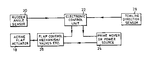
Figure 2 is a schematic layout of the control
system and,
Figure 3 is a plan view of the active flap/main
rudder assembly,
As shown in Figure 1, a main rudder 10 rotates
i about rudderstock axis 12. ~t the trailing end 14 of
I the rudder is a hinged portion that constitutes the
active flap 16. A control system, shown in more detail
in Figure 2, moves the active flap actuator 18 and thus
the active flap to port or starboardD This movement is
independent of the main rudder movement but controls the
main rudder for movement in an opposite direction.
Movements are initiated by a towline direction sensor or
by radio telemetry.
Blocks 5, 6 and 22 represent the power pack on the
barge that is linked to the remote control system.
Hydraulic units 5 with control valves 6 provide one
link. Electronic control unit 22 is a second link.
rudder angle sensor 20 i~ shown in the control system
layout of Figure 2. The drive between the flap actuator
and the flap may be in the form of a rotary vane
cylinder, single or multiple rams, gear drive, chain
drive or other mechanical equivalents.
, .
., ,~, j
. .

~2~Z,~
~ 'igure 2 shows the control system with the
components labeled Eor clarification~
Figure 3 shows the active ~lap hinge axis 18, khe
main rudder axis 12 and the directions of movement of
the active flap and main rudder.
~(
-`'
~'
';; '
.,
;'
;
:
."', .
"
;
:,

Representative Drawing
A single figure which represents the drawing illustrating the invention.
Administrative Status

2024-08-01:As part of the Next Generation Patents (NGP) transition, the Canadian Patents Database (CPD) now contains a more detailed Event History, which replicates the Event Log of our new back-office solution.

Please note that "Inactive:" events refers to events no longer in use in our new back-office solution.

For a clearer understanding of the status of the application/patent presented on this page, the site Disclaimer , as well as the definitions for Patent , Event History , Maintenance Fee  and Payment History  should be consulted.

Event History

Description Date
Inactive: IPC from MCD 2006-03-11
Inactive: Inventor deleted 1999-08-09
Inactive: Adhoc Request Documented 1993-10-10
Time Limit for Reversal Expired 1993-04-11
Letter Sent 1992-10-12
Grant by Issuance 1989-10-10

Abandonment History

There is no abandonment history.

Owners on Record

Note: Records showing the ownership history in alphabetical order.

Current Owners on Record
JOHN S. MACKENZIE
Past Owners on Record
None
Past Owners that do not appear in the "Owners on Record" listing will appear in other documentation within the application.
Documents

To view selected files, please enter reCAPTCHA code :


To view images, click a link in the Document Description column. To download the documents, select one or more checkboxes in the first column and then click the "Download Selected in PDF format (Zip Archive)" or the "Download Selected as Single PDF" button.

List of published and non-published patent-specific documents on the CPD .

If you have any difficulty accessing content, you can call the Client Service Centre at 1-866-997-1936 or send them an e-mail at CIPO Client Service Centre.


Document
Description 
Date
(yyyy-mm-dd) 
Number of pages   Size of Image (KB) 
Abstract 1993-09-13 1 19
Drawings 1993-09-13 1 20
Claims 1993-09-13 1 25
Descriptions 1993-09-13 3 99
Representative drawing 2001-09-27 1 11
Fees 1992-01-26 2 62
Fees 1991-10-07 1 103
Fees 1992-02-19 1 22