Language selection

Search

Patent 1262338 Summary

Third-party information liability

Some of the information on this Web page has been provided by external sources. The Government of Canada is not responsible for the accuracy, reliability or currency of the information supplied by external sources. Users wishing to rely upon this information should consult directly with the source of the information. Content provided by external sources is not subject to official languages, privacy and accessibility requirements.

Claims and Abstract availability

Any discrepancies in the text and image of the Claims and Abstract are due to differing posting times. Text of the Claims and Abstract are posted:

  • At the time the application is open to public inspection;
  • At the time of issue of the patent (grant).
(12) Patent: (11) CA 1262338
(21) Application Number: 1262338
(54) English Title: FLANGED RING FOR PIPES
(54) French Title: BAGUE A BRIDE POUR TUYAU
Status: Expired and beyond the Period of Reversal
Bibliographic Data
(51) International Patent Classification (IPC):
  • F16L 23/00 (2006.01)
  • F16L 23/14 (2006.01)
(72) Inventors :
  • MEINIG, MANFRED (Germany)
(73) Owners :
  • MANFRED MEINIG
(71) Applicants :
(74) Agent: AVENTUM IP LAW LLP
(74) Associate agent:
(45) Issued: 1989-10-17
(22) Filed Date: 1986-04-30
Availability of licence: N/A
Dedicated to the Public: N/A
(25) Language of filing: English

Patent Cooperation Treaty (PCT): No

(30) Application Priority Data:
Application No. Country/Territory Date
P 35 15 737.2 (Germany) 1985-05-02

Abstracts

English Abstract


ABSTRACT
To further stabilize a flange ring,
mounted on a thin sheet metal pipe end in accordance
with West German Patent No. 31 43 893, a second leg,
parallel to the first, is provided which, on the one
hand, results in an additional reinforcement and, on
the other hand, has an additional annular projection,
which can also be driven into the pipe interior under
initial pressure. This projection can also be
designed in the form of a second ring land. For
further security, the first ring land can snap in
behind a rim of support projections which extend
inward from the sheet metal pipe.


Claims

Note: Claims are shown in the official language in which they were submitted.

The embodiments of the invention in which
an exclusive property or privilge is claimed are
defined as follows:
1. A one-piece flange ring which can be
mounted onto a thin-walled round sheet metal pipe to
make a butt joint between two pipe sections, having a
mounting flange, extending approximately radially
outward, a first leg projecting from the inner end of
the mounting flange and a first ring land, extending
from the first leg and bent diagonally outward to the
mounting flange, whereby the first leg and the first
ring land can be driven into the pipe under initial
stress, the flange ring having a second leg adjacent
and parallel to the first leg, and an annular
projection, projecting outward from said second leg,
which can be driven into the pipe under initial
stress.
2. A flange ring according to claim 1, in
that the annular projection is formed as a second ring
land which proceeds from the second leg and is bent
diagonally outward to the mounting flange.
3. A flange ring according to claim 1 or
2, in which the outer edge of the first ring land can
be snapped behind support projections which extend
inward in the vicinity of the end of the sheet metal
pipe section.
4. A flange ring according to claim 2, in
which the outer edge of the second ring land can be
snapped in behind support projections which extend
inwardly in the vicinity of the end of the sheet metal
pipe section.

5. A flange ring according to claim 2, in
which the outer edge of the first ring land can be
snapped behind support projections which extend inward
in the vicinity of the end of the sheet metal pipe
section and in which the outer edge of the second ring
land can be snapped in behind support projections
which extend inwardly in the vicinity of the end of
the sheet metal pipe section.

Description

Note: Descriptions are shown in the official language in which they were submitted.


3;~
01 The invention relates to a flange ring
02 which can be mounted onto a thin-walled round sheet
03 metal pipe to make a butt joint between two pipe
04 sections.
05 A flange ring of this type is known from
05 West German Patent 31 43 893. Under normal stress, it
07 i9 completely stable in the pipe end, since the ring
08 land, driven in under initial pressure, struts itself
09 strongly enough on the inner wall of the pipe.
However, if strong bending strains occur, then it may
11 be desirable to further reinforce the cohesion of the
12 flange ring in the pipe end.
13 It is an object of the present invention
14 to attain such additional stabilization of the flange
ring in the pipe end.
16 According to the invention a one-piece
17 flange ring can be mounted onto a thin-walled round
18 sheet metal pipe to make a butt joint between two pipe
19 sections, having a mounting flange, extending
approximately radially outward, a first leg projecting
21 from the inner end of the mounting flange and a first
22 ring land, extending from the first leg and bent
23 diagonally outward to the mounting flange, whereby the
24 first leg and the first ring land can be driven into
the pipe under initial stress, the flange ring having
26 a second leg adjacent and parallel to the first leg,
27 and an annular projection projecting outward from said
28 second leg, which can be driven into the pipe under
29 initial pressure.
The cohesion of the flange ring in the
31 pipe end can thereby be practically doubled.
32 ManuEacture and assembly of the flange ring become,
33 however, only negligibly more complicated due to these
34 measures.
The annular projection can alternatively
36 be pressed outwardly from the second leg, so that it
37 abuts against the inner wall of the pipe from the
38 - 1 -
~'~

~l~6~38
01 inside under initial pressure. According to a
02 preferred embodiment, it is comprised of a second ring
03 land, which is bent in the same manner as the first
04 ring land and whose outer edge struts itelf against
05 removal from the pipe under initial pressure.
06 To further reinforce the cohesion of the
07 flange ring in the pipe end, the first and/or second
08 ring land can be snapped in behind each of a rim of
09 support projections, which extend inwardly from the
inner surface of the pipe. For practical purposes,
11 the support projections are comprised of cams, which
12 are pressed inwardly from the pipe wall.
13 Embodiments of the invention are described
14 in greater detail below with reference to the
drawings, in which:
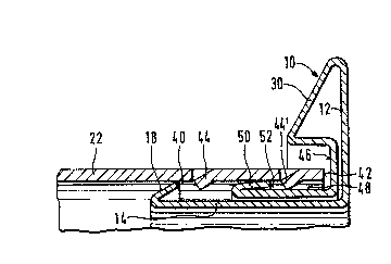
16 Figure 1 is an axial partial section
17 through a pipe end with the flange ring prior to
18 mounting on the pipe end,
19 Figure 2 illustrates the parts shown in
Figure 1 after mounting of the flange ring, and
21 Figure 3 is a partial section
22 corresponding to Figure 2 with a second embodiment of
23 the -flange ring.
24 Similar or corresponding parts are
designated with the same reference numbers as in the
26 aforenoted German patent.
27 The flange ring, generally designated as
28 10, has a radial mounting flange 12, a first leg 14,
29 approximately at right angles to it, that is,
extending approximately axially, and a first ring land
31 18 bent diagonally outward from the leg 14 toward the
32 mounting flange 12. In the no-load condition of the
33 flange ring 10, shown in Figure 1, the largest
34 diameter of the first ring land 18 is larger at its
outer edge 40 than the inside diameter of the pipe 22,
36 into whose open end 42 the flange ring 10 is to be
37 driven in under initial pressure of the first ring
38 - 2 -

~ZgiZ3~
01 land 18, as can be seen in Figure 2.
02 While being driven in, the outer edge 40
03 glides along the inner wall of the pipe 22 until it
04 snaps in behind a rim of support projections 44, which
05 are pressed inward in the form of cams from the wall
06 of pipe 22. As a result of the longer construction of
07 the first leg 14, the tolerance of the distance of the
08 support projections 44 from the open pipe end 42 is
09 not particularly critical which, in particular,
represents a considerable facility with inaccurate
11 cutting of the pipe at the construction site.
12 A clamp part 30, bent over by more than
13 gO to the same axial side as leg 14, is provided at
14 the outer end of the mounting flange 12, a part 46,
coming to rest at the mounting flange 12, connects to
16 the end of the clamp part 30 for a better
17 reinforcement of the flange ring 10. The part 46, in
18 turn, turns into a second leg 48 which comes to rest
19 at the first leg 14 and serves as an additional
reinforcement. A second ring land 50, bent diagonally
21 toward the mounting flange 12, proceeds from the
22 second leg 48 for additional bracing at the inner wall
23 of the pipe, similar to -the first ring land 18. The
24 second leg 48 is made shorter in this embodiment than
the first leg 14, so that the outer edge 52 of the
26 second ring land 50 braces itself at the inner wall of
27 the pipe 22 outside of the support projections 44. A
28 second rim of support projections 44' is provided
29 behind which the outer edge 52 snaps in for an
additional securing of the flange ring 10.
31 In the embodiment according to Figure 3,
32 most of the parts are constructed essentially the same
33 as in the embodiment shown in Figures 1 and 2. The
34 same reference numbers are, therefore, used herefor.
In this embodiment, the second leg 48 is simply made
36 almost as long as the first leg 14 and, thus, abuts
37 over almost the entire length of the first leg in a
38 - 3 -

3~
01 propping manner against this first leg. Instead of a
02 second ring land, a reinforcing seam 54, bracing
03 itself on the inner wall of the pipe and pressed
04 radially outward, is provided. The outer edge 56 of
05 the reinforcing seam 54 also braces itself under
06 initial pressure on the inner wall of the pipe 23
07 while being driven into the open end 42 of -the pipe
08 22.
09 - 4 -

Representative Drawing
A single figure which represents the drawing illustrating the invention.
Administrative Status

2024-08-01:As part of the Next Generation Patents (NGP) transition, the Canadian Patents Database (CPD) now contains a more detailed Event History, which replicates the Event Log of our new back-office solution.

Please note that "Inactive:" events refers to events no longer in use in our new back-office solution.

For a clearer understanding of the status of the application/patent presented on this page, the site Disclaimer , as well as the definitions for Patent , Event History , Maintenance Fee  and Payment History  should be consulted.

Event History

Description Date
Inactive: IPC from MCD 2006-03-11
Time Limit for Reversal Expired 2005-10-17
Letter Sent 2004-10-18
Grant by Issuance 1989-10-17

Abandonment History

There is no abandonment history.

Fee History

Fee Type Anniversary Year Due Date Paid Date
MF (category 1, 8th anniv.) - small 1997-10-17 1997-10-09
MF (category 1, 9th anniv.) - small 1998-10-19 1998-09-21
MF (category 1, 10th anniv.) - small 1999-10-18 1999-09-16
MF (category 1, 11th anniv.) - small 2000-10-17 2000-09-21
MF (category 1, 12th anniv.) - small 2001-10-17 2001-09-19
MF (category 1, 13th anniv.) - small 2002-10-17 2002-09-03
MF (category 1, 14th anniv.) - small 2003-10-17 2003-08-29
Owners on Record

Note: Records showing the ownership history in alphabetical order.

Current Owners on Record
MANFRED MEINIG
Past Owners on Record
None
Past Owners that do not appear in the "Owners on Record" listing will appear in other documentation within the application.
Documents

To view selected files, please enter reCAPTCHA code :


To view images, click a link in the Document Description column. To download the documents, select one or more checkboxes in the first column and then click the "Download Selected in PDF format (Zip Archive)" or the "Download Selected as Single PDF" button.

List of published and non-published patent-specific documents on the CPD .

If you have any difficulty accessing content, you can call the Client Service Centre at 1-866-997-1936 or send them an e-mail at CIPO Client Service Centre.


Document
Description 
Date
(yyyy-mm-dd) 
Number of pages   Size of Image (KB) 
Cover Page 1993-09-14 1 14
Abstract 1993-09-14 1 13
Claims 1993-09-14 2 41
Drawings 1993-09-14 1 34
Descriptions 1993-09-14 4 130
Representative drawing 2001-06-26 1 11
Maintenance Fee Notice 2004-12-13 1 173
Fees 1997-10-09 1 38
Fees 1997-10-09 1 37
Fees 1996-08-23 2 87
Fees 1995-10-17 1 34
Fees 1994-10-07 1 24
Fees 1993-10-01 1 39
Fees 1992-09-04 1 33
Fees 1991-08-22 1 25
Fees 1989-08-14 1 26